EP2199983A1 - Verfahren zur Schätzung einer Bewegung eines Systems mit mehreren Kameras, System mit mehreren Kameras und Computerprogrammprodukt - Google Patents
Verfahren zur Schätzung einer Bewegung eines Systems mit mehreren Kameras, System mit mehreren Kameras und Computerprogrammprodukt Download PDFInfo
- Publication number
- EP2199983A1 EP2199983A1 EP08172567A EP08172567A EP2199983A1 EP 2199983 A1 EP2199983 A1 EP 2199983A1 EP 08172567 A EP08172567 A EP 08172567A EP 08172567 A EP08172567 A EP 08172567A EP 2199983 A1 EP2199983 A1 EP 2199983A1
- Authority
- EP
- European Patent Office
- Prior art keywords
- motion
- parameters
- image
- camera system
- bias
- Prior art date
- Legal status (The legal status is an assumption and is not a legal conclusion. Google has not performed a legal analysis and makes no representation as to the accuracy of the status listed.)
- Withdrawn
Links
Images


Classifications
-
- G—PHYSICS
- G06—COMPUTING; CALCULATING OR COUNTING
- G06T—IMAGE DATA PROCESSING OR GENERATION, IN GENERAL
- G06T7/00—Image analysis
- G06T7/97—Determining parameters from multiple pictures
-
- G—PHYSICS
- G06—COMPUTING; CALCULATING OR COUNTING
- G06T—IMAGE DATA PROCESSING OR GENERATION, IN GENERAL
- G06T7/00—Image analysis
- G06T7/20—Analysis of motion
- G06T7/285—Analysis of motion using a sequence of stereo image pairs
-
- G—PHYSICS
- G06—COMPUTING; CALCULATING OR COUNTING
- G06V—IMAGE OR VIDEO RECOGNITION OR UNDERSTANDING
- G06V10/00—Arrangements for image or video recognition or understanding
- G06V10/70—Arrangements for image or video recognition or understanding using pattern recognition or machine learning
- G06V10/74—Image or video pattern matching; Proximity measures in feature spaces
- G06V10/75—Organisation of the matching processes, e.g. simultaneous or sequential comparisons of image or video features; Coarse-fine approaches, e.g. multi-scale approaches; using context analysis; Selection of dictionaries
- G06V10/757—Matching configurations of points or features
Definitions
- the present invention relates to a method of correcting a bias in a motion estimation of a multiple camera system in a three-dimensional (3D) space, wherein the fields of view of multiple cameras at least partially coincide, the method comprising the steps of providing a subsequent series of image sets that have substantially simultaneously been captured by the multiple camera system, identifying a multiple number of corresponding image features in a particular image set, determining 3D positions associated with said image features based on a disparity in the images in the particular set, determining 3D positions associated with said image features in a subsequent image set, computing a first and second set of distribution parameters associated with corresponding determined 3D positions and estimating a set of motion parameters representing a motion of the multiple camera system between the time instant associated with the particular image set and the time instant of the subsequent image set, based on 3D position differences of image features in images of the particular set and the subsequent set.
- the method can e.g. be applied for accurately ego-motion estimation of a moving stereo-camera. If the camera is mounted on a vehicle this is also known as stereo-based visual-odometry.
- Stereo-processing allows estimation of the three dimensional (3D) location and associated uncertainty of landmarks observed by a stereo-camera.
- 3D point clouds can be obtained for each stereo-frame.
- the point clouds of two successive stereo-frames i.e. from t - 1 to t , can be related to each other. From these two corresponding point clouds the pose at t relative to the pose at t - 1 can be estimated.
- the position and orientation of the stereo-rig in the global coordinate frame can be tracked by integrating all the relative-pose estimates.
- HEIV Heteroscedastic Error-In-Variables
- vision based approaches for ego-motion estimation are susceptible to outlier landmarks.
- Sources of outlier landmarks range from sensor noise, correspondences errors, to independent moving objects such as cars or people that are visible in the camera views.
- Robust estimation techniques such as RANSAC are therefore frequently applied.
- RANSAC Robust estimation techniques
- Recently, a method using Expectation Maximization on a local linearization, obtained by using Riemannian geometry, of the motion space SE(3) has been proposed. In the case of visual-odometry this approach has advantages in terms of accuracy and efficiency.
- the method further comprises the steps of improving the computed first or second set of distribution parameters using the computed second or first set of distribution parameters, respectively, and using the estimated set of motion parameters, improving the estimated set of motion parameters using the improved computation of the set of distribution parameters, and calculating a bias direction based on the initially estimated set of motion parameters and on the improved estimated set of motion parameters.
- a bias direction can be calculated for improving the set of motion parameters, thereby reducing the bias.
- the bias can be reduced providing accurate visual-odometry results for loop-less trajectories without relying on auxiliary sensors, (semi-)global optimization or loop-closing.
- a drift in stereo-vision based relative-pose estimates is related to structural errors i.e. bias in the optimization process.
- the invention also relates to a multiple camera system.
- a computer program product may comprise a set of computer executable instructions stored on a data carrier, such as a CD or a DVD.
- the set of computer executable instructions which allow a programmable computer to carry out the method as defined above, may also be available for downloading from a remote server, for example via the Internet.
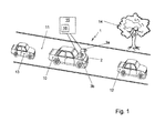
- Figure 1 shows a schematic perspective view of a multiple camera system 1 according to the invention.
- the system 1 comprises a frame 2 carrying two cameras 3a, 3b that form a stereo-rig.
- the camera system 1 is mounted on a vehicle 10 that moves in a 3D space, more specifically on a road 11 between other vehicles 12, 13.
- a tree 14 is located near the road 11.
- the multiple camera system 1 is arranged for capturing pictures for further processing, e.g. for analyzing crime scenes, accident sites or for exploring areas for military or space applications. Thereto, the field of view of the cameras 3a, 3b at least partially coincides. Further, multiple camera system can be applied for assisting and/or autonomously driving vehicles.
- the multiple camera system comprises a computer system 15 provided with a processor 16 that is arranged for processing the captured images such that an estimation of the camera system motion in the 3D space is obtained.
- the camera system 1 is provided with an attitude and heading reference system (AHRS), odometry sensors and/or a geographic information system (GIS).
- AHRS attitude and heading reference system
- GIS geographic information system
- a bias in a motion estimation of a multiple camera system in a three-dimensional (3D) space is corrected.
- Figure 2a shows a coordinate system and a camera image quadrant specification.
- the coordinate system 19 includes coordinate axes x, y and z. Further, rotations such as pitch P, heading H and roll R can be defined.
- a captured image 20 may include four quadrants 20, 21, 22, 23.
- Figure 2b shows an exemplary camera image 20 with inliers 24a, b, also called landmarks,
- v i and u i are noise free coordinates of a particular landmark observed at time instants t and t + 1 relative to the coordinate frame of the moving camera system 1.
- M ⁇ i v ⁇ x - u ⁇ x 0 - v ⁇ z - u ⁇ z v ⁇ y - u ⁇ y v ⁇ y - u ⁇ y v ⁇ z - u ⁇ z 0 - v ⁇ x - u ⁇ x v ⁇ z - u ⁇ z - u ⁇ y v ⁇ x + u ⁇ x 0 .
- v i and u i are not observed directly.
- ⁇ v i and ⁇ u i are drawn from a symmetric and independent distribution with zero mean and data dependent covariance S(0, ⁇ v i ) and S(0, ⁇ u i ) respectively. It is thus assumed that the noise can be described using a Gaussian distribution. Note that the covariance only need to be known up to a common scale factor ⁇ .
- the noise governing the observed data is modeled as heteroscedastic i.e. anisotropic and inhomogeneous.
- the benefit of using a so-called HEIV estimator is that it can find an optimal solution for both the rotation as well as the translation for data perturbed by heteroscedastic noise.
- Analog to eq. 1 the observed landmarks can be combined into the matrix M .
- the noise effecting w i will be denoted as C i , it can be computed from ⁇ z i and ⁇ u i .
- a solution to this non-linear problem can be obtained by iteratively solving a generalized Eigen problem.
- ⁇ z i can be replaced with ⁇ z i , eq. 7 becomes eq. 5.
- ⁇ z i ⁇ z i is a slightly invalid assumption for stereo-reconstruction uncertainty and causes a small bias in the estimate of the motion parameters. Since the absolute pose is the integration of possible thousands of relative motion estimates, this small bias will eventually cause a significant drift. The reason why the assumption is often made is that z i is unobservable, therefore ⁇ z i is also unknown, while ⁇ z i is straightforward to estimate.
- SIFT Scale Invariant Feature Transform
- the method thus comprises the steps of providing a subsequent series of image sets that have substantially simultaneously been captured by the multiple camera system, identifying a multiple number of corresponding image features in a particular image set, determining 3D positions associated with said image features based on a disparity in the images in the particular set, and determining 3D positions associated with said image features in a subsequent image set.
- the image features are inliers.
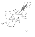
- FIG. 3a shows a perspective side view of an imaged inlier z having projections z l and z r on the images 20a, 20b. End sections 28a, 28b of the intersection 27 represent edges of the uncertainty in the position of the inlier z.
- Figure 3b shows a perspective top view of the imaged inlier of z Fig. 3a . It is clearly shown in Fig. 3b that the uncertainty may be asymmetric.
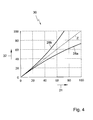
- Figure 4 shows a diagram 30 of uncertainty in the determination of the inlier position z , wherein intersection end sections 28a, 28b as well as the true position z are depicted as a function of the distance 31, 32 in meters. Again, the asymmetric behaviour is clearly shown.
- the method thus comprises the step of computing a first and second set of distribution parameters associated with corresponding determined 3D positions.
- the method also comprises the step of estimating a set of motion parameters representing a motion of the multiple camera system between the time instant associated with the particular image set and the time instant of the subsequent image set, based on 3D position differences of image features in images of the particular set and the subsequent set.
- Such an estimating step may e.g. be performed using the HEIV approach.
- the method further comprises the step of improving the computed first or second set of distribution parameters using the computed second or first set of distribution parameters, respectively, and using the estimated set of motion parameters.
- the step of estimating a set of motion parameters is also based on the computed first and second set of distribution parameters.
- the motion parameters include 3D motion information and 3D rotation information of the multiple camera system.
- a copy of the fused landmark positions is transformed according to the inverse of estimated motion.
- the process results in an improved estimate of the landmark positions which exactly obey the estimated motion.
- the real goal is an improved estimate of the landmark uncertainties.
- the new estimates v ⁇ i and û i can be projected to the imaging planes of a (simulated) stereo-camera.
- the appropriate stereo camera parameters can be obtained by calibration of the actual stereo camera used. From these projections, v ⁇ i and û i , an improved estimate of the covariances, i.e. ⁇ v ⁇ i and ⁇ û i , can be obtained with eq. 9 and eq. 10.
- This technique is preferred because it produces covariances with the correct orientation and scale given v ⁇ i and û i .
- the step of improving the computed first or second set of distribution parameters comprises the substeps of mapping corresponding positions of image features in images of the particular set and the subsequent set, constructing improved 3D positions of the mapped image features, remapping the constructed improved 3D positions, and determining improved covariance parameters.
- the inlier in a further image is mapped back to an earlier time instant, obviously, however, the inlier might also initially be mapped to a further time instant.
- a part of a Kalman filter is used to construct an improved 3D position.
- a weighted means is determined, based on covariances. Also other fusing algorithms can be applied.
- a premisses of the proposed bias reduction technique is the absence of landmark outliers.
- An initial robust estimate of the motion can be obtained using known techniques. Given the robust estimate the improved location and uncertainty of the landmarks can be calculated with eq. 11 and eq. 12. Landmarks can then be discarded based on their Mahalanobis distance to the improved landmark positions v i - v ⁇ i T ⁇ ⁇ ⁇ v ⁇ i ⁇ v i - v ⁇ i + u i - u ⁇ i T ⁇ ⁇ ⁇ u ⁇ i ⁇ u i - u ⁇ i .
- a new motion estimate is then calculated using all the inliers. The process can be iterated several times or until convergence.
- the method thus comprises thus the step of improving the estimated set of motion parameters using the improved computation of the set of distribution parameters.
- ⁇ x , ⁇ y and ⁇ z are the appropriate gains that scale the estimated tendency of the translation bias to the correct magnitude.
- the method includes the step of calculating a bias direction based on the initially estimated set of motion parameters and on the improved estimated set of motion parameters, so that a corrected for the bias can be realized.
- the method comprises a step of estimating an absolute bias correction, including multiplying the calculated bias direction by bias gain factors.
- the bias gains are denoted as constants.
- the gains can be the results of functions that depend on the input data.
- the artificial points u i ?? u 150 were generated homogenously within the space defined by the optical center of the left camera and the first image quadrant, as shown in Fig. 2a .
- the distances of the generated landmarks ranged from 5 m to 150 m.
- the points v i ?? v 150 were then generated by transforming u i Vietnamese u 150 with the groundtruth motion R and t . These 3D points were projected onto the imaging planes of a simulated stereo-camera and ⁇ v i and ⁇ u i were calculated using eq. 9 and 10.
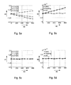
- FIG. 5a-d showing a bias in motion parameters in the first quadrant 21.
- the motions have a constant heading of 1 degree and an increasing translation over the z- axis.
- Fig. 5a and c relate to translations 41 [mm] as a function of a translation over the z-axis 40 [mm] while
- Fig. 5b and d relate to rotations 42 [degrees] as a function of a translation over the z-axis.
- Fig. 5a and b relate to an approach wherein ⁇ z is modeled with ⁇ z
- Fig. 5c and d relate to an approach wherein ⁇ z is used for the computation. It can clearly be seen that using the general heteroscedastic model of eq.
- the artificial landmarks u i ?? u 150 and v i ?? v 150 were generated similarly to the approach described above.
- quadrant 2 and quadrant 3 see Fig. 2a .
- the dependency of the bias on the landmark distribution can be visualized.
- FIG. 2b A real-world example of a situation in which the landmarks are not homogenously distributed is shown in Fig. 2b .
- the landmarks were projected onto the imaging planes of a simulated stereo-camera.
- isotropic i.i.d. gaussian noise (with standard deviation of 0.25 pixel) is added to the image projections.
- the landmark positions are estimated resulting in u i ?? u 150 and v i ?? v 150 .
- ⁇ v i and ⁇ u i were estimated, using eq. 9 and 10 from the noisy image points.
- H EIV H EIV ( v , ⁇ v , u , ⁇ u ) and the experiment is repeated one thousand times for nine different motions.
- the results for different landmark distributions is shown in Fig. 6a-d .
- a bias in motion parameters The motions have a constant heading of 1 degree and an increasing translation over the z- axis.
- FIG. 6a and c relate to translations 41 [mm] as a function of a translation over the z-axis 40 [mm] in the second and third quadrant, respectively, while Fig. 6b and d relate to rotations 42 [degrees] as a function of a translation over the z-axis in the second and third quadrant, respectively.
- the result of applying the bias reduction technique according to the method of the invention is shown in Fig. 7a-d .
- the used bias gains ( ⁇ x , ⁇ y , ⁇ z , ⁇ p , ⁇ h , ⁇ r ) were all set to 0.8.
- the benefit of the proposed bias reduction technique is clearly visible. It is noted that the mean absolute error in motion parameters did not change by using the bias reduction technique.
- the data-set was recorded using a stereo-camera with a baseline of 40 cm and an image resolution of 640 by 480 pixels running at 30 Hz.
- the correct values for the real-world bias gains ( ⁇ x , ⁇ y , ⁇ z , ⁇ p , ⁇ h , ⁇ r ) were obtained by manual selection, such that the loop in a calibration data-set, see Fig. 8 , was approximately closed in 3D.
- a first trajectory in a first map is a DGPS based groundtruth 50, while a second trajectory 51 is computed using the method according to the invention.
- a first trajectory 50 shows a DGPS based groundtruth
- a second trajectory 52 shows a motion estimation without bias correction
- a third trajectory 53 shows a motion estimation with bias correction according to a method according to the invention.
- FIG. 10 shows an estimated height profile 60, viz. a height 61 [m] as a function of a travelled distance 62 [km], both for uncorrected and corrected bias. Due to bias in the estimated roll angle the trajectory without bias reduction spirals downward. By compensation the bias in roll, using the proposed technique, this spiraling effect is significantly reduced. Due to these biased rotation estimates the error in the final pose as percentage of the traveled distance, when not using the bias reduction technique, was approximately 20%. This reduced to 1% when the proposed bias reduction technique was used. The relative computation time of the most intensive processing stages were approximately, 45% for image-feature extraction and matching and 45% for obtaining the robust motion estimate. The relative computation time of the bias reduction technique was only 4%.
- the method according to the invention significantly reduces the structural error in stereo-vision based motion estimation.
- the benefit of this approach is most apparent when the relative-pose estimates are integrated to track the absolute-pose of the camera, as is the case with visual-odometry.
- the proposed method has been tested on simulated data as well as a challenging real-world urban trajectory of 5 km. The results show a clear reduction in drift, whereas the needed computation time is only 4% of the total computation time needed.
- the method of estimating a motion of a multiple camera system in a 3D space can be performed using dedicated hardware structures, such as FPGA and/or ASIC components. Otherwise, the method can also at least partially be performed using a computer program product comprising instructions for causing a processor of the computer system to perform the above described steps of the method according to the invention.
- Figure 11 shows a flow chart of an embodiment of the method according to the invention.
- a method is used for correcting a bias in a motion estimation of a multiple camera system in a three-dimensional (3D) space, wherein the fields of view of multiple cameras at least partially coincide.
- the method comprises the steps of providing (100) a subsequent series of image sets that have substantially simultaneously been captured by the multiple camera system, identifying (110) a multiple number of corresponding image features in a particular image set, determining (120) 3D positions associated with said image features based on a disparity in the images in the particular set, determining (130) 3D positions associated with said image features in a subsequent image set, computing (140) a first and second set of distribution parameters associated with corresponding determined 3D positions, estimating (150) a set of motion parameters representing a motion of the multiple camera system between the time instant associated with the particular image set and the time instant of the subsequent image set, based on 3D position differences of image features in images of the particular set and the subsequent set, improving (160) the computed first or second set of distribution parameters using the computed second or first set of distribution parameters, respectively, and using the estimated set of motion parameters, improving (170) the estimated set of motion parameters using the improved computation of the set of distribution parameters, and calculating (180) a bias direction based on the initially estimated
- the system according to the invention can also be provided with more than two cameras, e.g. three, four or more cameras having a field of view that at least partially coincides.
- the cameras described above are arranged for capturing visible light images. Obviously, also cameras that are sensible to other electromagnetic ranges can be applied, e.g. infrared cameras.
- the system can also be mounted on another vehicle type, e.g. a flying platform such as a plane.
- a flying platform such as a plane.
- the multiple camera system according to the invention can implemented as a handheld device.
- bias gain values instead of using experimentally determined bias gain values, also other techniques can be used, e.g. noise based techniques, such as an off-line automated calibration procedure using simulated annealing. Furthermore, the effect of neglecting the asymmetry of the stereo-reconstruction uncertainty on the motion estimates may be used as a starting point for finding a bias direction.
- noise based techniques such as an off-line automated calibration procedure using simulated annealing.
- the effect of neglecting the asymmetry of the stereo-reconstruction uncertainty on the motion estimates may be used as a starting point for finding a bias direction.
Priority Applications (4)
| Application Number | Priority Date | Filing Date | Title |
|---|---|---|---|
| EP08172567A EP2199983A1 (de) | 2008-12-22 | 2008-12-22 | Verfahren zur Schätzung einer Bewegung eines Systems mit mehreren Kameras, System mit mehreren Kameras und Computerprogrammprodukt |
| US13/141,312 US20110316980A1 (en) | 2008-12-22 | 2009-12-21 | Method of estimating a motion of a multiple camera system, a multiple camera system and a computer program product |
| PCT/NL2009/050789 WO2010074567A1 (en) | 2008-12-22 | 2009-12-21 | A method of estimating a motion of a multiple camera system, a multiple camera system and a computer program product |
| EP09775355A EP2380136B1 (de) | 2008-12-22 | 2009-12-21 | Verfahren zur schätzung einer bewegung eines mehrkamerasystems, mehrkamerasystem und computerprogrammprodukt |
Applications Claiming Priority (1)
| Application Number | Priority Date | Filing Date | Title |
|---|---|---|---|
| EP08172567A EP2199983A1 (de) | 2008-12-22 | 2008-12-22 | Verfahren zur Schätzung einer Bewegung eines Systems mit mehreren Kameras, System mit mehreren Kameras und Computerprogrammprodukt |
Publications (1)
| Publication Number | Publication Date |
|---|---|
| EP2199983A1 true EP2199983A1 (de) | 2010-06-23 |
Family
ID=41010848
Family Applications (2)
| Application Number | Title | Priority Date | Filing Date |
|---|---|---|---|
| EP08172567A Withdrawn EP2199983A1 (de) | 2008-12-22 | 2008-12-22 | Verfahren zur Schätzung einer Bewegung eines Systems mit mehreren Kameras, System mit mehreren Kameras und Computerprogrammprodukt |
| EP09775355A Active EP2380136B1 (de) | 2008-12-22 | 2009-12-21 | Verfahren zur schätzung einer bewegung eines mehrkamerasystems, mehrkamerasystem und computerprogrammprodukt |
Family Applications After (1)
| Application Number | Title | Priority Date | Filing Date |
|---|---|---|---|
| EP09775355A Active EP2380136B1 (de) | 2008-12-22 | 2009-12-21 | Verfahren zur schätzung einer bewegung eines mehrkamerasystems, mehrkamerasystem und computerprogrammprodukt |
Country Status (3)
| Country | Link |
|---|---|
| US (1) | US20110316980A1 (de) |
| EP (2) | EP2199983A1 (de) |
| WO (1) | WO2010074567A1 (de) |
Cited By (4)
| Publication number | Priority date | Publication date | Assignee | Title |
|---|---|---|---|---|
| EP3187953A1 (de) * | 2015-12-30 | 2017-07-05 | Honda Research Institute Europe GmbH | Autonome arbeitsmaschine wie ein autonomer rasenmäher |
| EP3327697A1 (de) * | 2010-09-24 | 2018-05-30 | iRobot Corporation | Systeme und verfahren zur vslam-optimierung |
| WO2022005840A1 (en) * | 2020-07-02 | 2022-01-06 | The Toro Company | Autonomous machine having vision system for navigation and method of using same |
| CN114581613A (zh) * | 2022-04-29 | 2022-06-03 | 杭州倚澜科技有限公司 | 一种基于轨迹约束的人体模型姿态和形状优化方法和系统 |
Families Citing this family (25)
| Publication number | Priority date | Publication date | Assignee | Title |
|---|---|---|---|---|
| US20110222757A1 (en) * | 2010-03-10 | 2011-09-15 | Gbo 3D Technology Pte. Ltd. | Systems and methods for 2D image and spatial data capture for 3D stereo imaging |
| US20120289836A1 (en) * | 2011-05-12 | 2012-11-15 | Osamu Ukimura | Automatic real-time display system for the orientation and location of an ultrasound tomogram in a three-dimensional organ model |
| US20140122016A1 (en) * | 2012-10-31 | 2014-05-01 | Caterpillar Inc. | Machine Positioning System Having Angular Rate Correction |
| US9189850B1 (en) * | 2013-01-29 | 2015-11-17 | Amazon Technologies, Inc. | Egomotion estimation of an imaging device |
| US9058683B2 (en) * | 2013-02-21 | 2015-06-16 | Qualcomm Incorporated | Automatic image rectification for visual search |
| KR101431373B1 (ko) * | 2013-02-26 | 2014-08-18 | 경북대학교 산학협력단 | 스테레오 정합을 이용한 차량의 움직임 측정 장치 |
| US9251587B2 (en) | 2013-04-05 | 2016-02-02 | Caterpillar Inc. | Motion estimation utilizing range detection-enhanced visual odometry |
| US9286717B2 (en) * | 2013-07-30 | 2016-03-15 | Hewlett-Packard Development Company, L.P. | 3D modeling motion parameters |
| US9303999B2 (en) * | 2013-12-30 | 2016-04-05 | Google Technology Holdings LLC | Methods and systems for determining estimation of motion of a device |
| US9342888B2 (en) * | 2014-02-08 | 2016-05-17 | Honda Motor Co., Ltd. | System and method for mapping, localization and pose correction of a vehicle based on images |
| US9277361B2 (en) | 2014-02-20 | 2016-03-01 | Google Inc. | Methods and systems for cross-validating sensor data acquired using sensors of a mobile device |
| KR101947935B1 (ko) * | 2014-12-22 | 2019-02-13 | 사이버옵틱스 코포레이션 | 3차원 측정 시스템의 갱신 보정 방법 |
| KR102507248B1 (ko) * | 2015-12-02 | 2023-03-06 | 에스케이하이닉스 주식회사 | 에고모션 추정 시스템 및 방법 |
| US10209081B2 (en) * | 2016-08-09 | 2019-02-19 | Nauto, Inc. | System and method for precision localization and mapping |
| US10453150B2 (en) | 2017-06-16 | 2019-10-22 | Nauto, Inc. | System and method for adverse vehicle event determination |
| CN109254579B (zh) * | 2017-07-14 | 2022-02-25 | 上海汽车集团股份有限公司 | 一种双目视觉相机硬件系统、三维场景重建系统及方法 |
| CN107564061B (zh) * | 2017-08-11 | 2020-11-20 | 浙江大学 | 一种基于图像梯度联合优化的双目视觉里程计算方法 |
| US11392131B2 (en) | 2018-02-27 | 2022-07-19 | Nauto, Inc. | Method for determining driving policy |
| US10634777B2 (en) * | 2018-05-30 | 2020-04-28 | Ford Global Technologies, Llc | Radar odometry for vehicle |
| US11188765B2 (en) * | 2018-12-04 | 2021-11-30 | Here Global B.V. | Method and apparatus for providing real time feature triangulation |
| US11435756B2 (en) * | 2019-12-01 | 2022-09-06 | Nvidia Corporation | Visual odometry in autonomous machine applications |
| CN111156997B (zh) * | 2020-03-02 | 2021-11-30 | 南京航空航天大学 | 一种基于相机内参在线标定的视觉/惯性组合导航方法 |
| US11893004B2 (en) * | 2020-08-26 | 2024-02-06 | Ford Global Technologies, Llc | Anomaly detection in multidimensional sensor data |
| DE102020212285A1 (de) | 2020-09-29 | 2022-03-31 | Myestro Interactive Gmbh | Verfahren zur räumlichen Bilderfassung mit Hilfe einer zwei Kameras aufweisenden Stereokamera sowie Verfahren zur Erzeugung einer redundanten Abbildung eines Messobjektes und Vorrichtung zur Durchführung der Verfahren |
| FR3129236B1 (fr) * | 2021-11-18 | 2023-09-29 | Continental Automotive | Procédé de détermination de l’orientation relative de deux véhicules |
Family Cites Families (3)
| Publication number | Priority date | Publication date | Assignee | Title |
|---|---|---|---|---|
| US6859549B1 (en) * | 2000-06-07 | 2005-02-22 | Nec Laboratories America, Inc. | Method for recovering 3D scene structure and camera motion from points, lines and/or directly from the image intensities |
| WO2007018523A2 (en) * | 2004-07-28 | 2007-02-15 | Sarnoff Corporation | Method and apparatus for stereo, multi-camera tracking and rf and video track fusion |
| US9766074B2 (en) * | 2008-03-28 | 2017-09-19 | Regents Of The University Of Minnesota | Vision-aided inertial navigation |
-
2008
- 2008-12-22 EP EP08172567A patent/EP2199983A1/de not_active Withdrawn
-
2009
- 2009-12-21 WO PCT/NL2009/050789 patent/WO2010074567A1/en active Application Filing
- 2009-12-21 EP EP09775355A patent/EP2380136B1/de active Active
- 2009-12-21 US US13/141,312 patent/US20110316980A1/en not_active Abandoned
Non-Patent Citations (5)
| Title |
|---|
| MATEI B C ET AL: "Estimation of Nonlinear Errors-in-Variables Models for computer Vision Applications", IEEE TRANSACTIONS ON PATTERN ANALYSIS AND MACHINE INTELLIGENCE, IEEE SERVICE CENTER, LOS ALAMITOS, CA, US, vol. 28, no. 10, 1 October 2006 (2006-10-01), pages 1537 - 1552, XP001523452, ISSN: 0162-8828 * |
| MATEI B ET AL: "Optimal rigid motion estimation and performance evaluation with bootstrap", PROCEEDINGS OF THE 1999 IEEE COMPUTER SOCIETY CONFERENCE ON COMPUTER VISION AND PATTERN RECOGNITION, JUNE 23-25, 1999; FORT COLLINS, COLORADO, IEEE, THE INSTITUTE OF ELECTRICAL AND ELECTRONICS ENGINEERS, INC, US, vol. 1, 23 June 1999 (1999-06-23), pages 339 - 347, XP010347685, ISBN: 978-0-7695-0149-9 * |
| MATTHIES L ET AL: "Error modeling in stereo navigation", IEEE JOURNAL ON ROBOTICS AND AUTOMATION, IEEE, USA, vol. 3, no. 3, 1 June 1987 (1987-06-01), pages 239 - 248, XP011217401, ISSN: 0882-4967 * |
| SUBBARAO R ET AL: "A Balanced Approach to 3D Tracking from Image Streams", MIXED AND AUGMENTED REALITY, 2005. PROCEEDINGS. FOURTH IEEE AND ACM IN TERNATIONAL SYMPOSIUM ON VIENNA, AUSTRIA 05-08 OCT. 2005, PISCATAWAY, NJ, USA,IEEE, 5 October 2005 (2005-10-05), pages 70 - 78, XP010856762, ISBN: 978-0-7695-2459-7 * |
| WANG H ET AL: "Correction of bias for motion estimation algorithms", PATTERN RECOGNITION LETTERS, ELSEVIER, AMSTERDAM, NL, vol. 23, no. 13, 1 November 2002 (2002-11-01), pages 1505 - 1514, XP004360416, ISSN: 0167-8655 * |
Cited By (5)
| Publication number | Priority date | Publication date | Assignee | Title |
|---|---|---|---|---|
| EP3327697A1 (de) * | 2010-09-24 | 2018-05-30 | iRobot Corporation | Systeme und verfahren zur vslam-optimierung |
| EP3187953A1 (de) * | 2015-12-30 | 2017-07-05 | Honda Research Institute Europe GmbH | Autonome arbeitsmaschine wie ein autonomer rasenmäher |
| US10321625B2 (en) | 2015-12-30 | 2019-06-18 | Honda Research Institute Europe Gmbh | Autonomous working machine such as autonomous lawn mower |
| WO2022005840A1 (en) * | 2020-07-02 | 2022-01-06 | The Toro Company | Autonomous machine having vision system for navigation and method of using same |
| CN114581613A (zh) * | 2022-04-29 | 2022-06-03 | 杭州倚澜科技有限公司 | 一种基于轨迹约束的人体模型姿态和形状优化方法和系统 |
Also Published As
| Publication number | Publication date |
|---|---|
| US20110316980A1 (en) | 2011-12-29 |
| EP2380136A1 (de) | 2011-10-26 |
| EP2380136B1 (de) | 2012-10-10 |
| WO2010074567A1 (en) | 2010-07-01 |
Similar Documents
| Publication | Publication Date | Title |
|---|---|---|
| EP2380136B1 (de) | Verfahren zur schätzung einer bewegung eines mehrkamerasystems, mehrkamerasystem und computerprogrammprodukt | |
| Fan et al. | Road surface 3D reconstruction based on dense subpixel disparity map estimation | |
| Jiao et al. | Robust odometry and mapping for multi-lidar systems with online extrinsic calibration | |
| Bloesch et al. | Iterated extended Kalman filter based visual-inertial odometry using direct photometric feedback | |
| US10096129B2 (en) | Three-dimensional mapping of an environment | |
| JP6854780B2 (ja) | 三次元空間のモデリング | |
| US10553026B2 (en) | Dense visual SLAM with probabilistic surfel map | |
| US10636151B2 (en) | Method for estimating the speed of movement of a camera | |
| US8447116B2 (en) | Identifying true feature matches for vision based navigation | |
| Parra et al. | Robust visual odometry for vehicle localization in urban environments | |
| EP3159126A1 (de) | Vorrichtung und verfahren zur detektion des standorts eines mobilen roboters mittels kantenbasierter nachjustierung | |
| EP3159125A1 (de) | Vorrichtung zur erkennung der position eines mobilen roboters mittels direkter verfolgung und verfahren dafür | |
| Sucar et al. | Bayesian scale estimation for monocular slam based on generic object detection for correcting scale drift | |
| EP3159122A1 (de) | Vorrichtung und -verfahren zur positionserkennung eines mobilen roboters anhand von suchbasierter korrelation anpassung | |
| Munoz-Banon et al. | Targetless camera-lidar calibration in unstructured environments | |
| CN110260866A (zh) | 一种基于视觉传感器的机器人定位与避障方法 | |
| CN112802096A (zh) | 实时定位和建图的实现装置和方法 | |
| Daraei et al. | Velocity and shape from tightly-coupled LiDAR and camera | |
| Peng et al. | Globally-optimal event camera motion estimation | |
| Dubbelman et al. | Bias reduction for stereo based motion estimation with applications to large scale visual odometry | |
| Dang et al. | Stereo calibration in vehicles | |
| Yang et al. | Visual SLAM using multiple RGB-D cameras | |
| García-García et al. | 3D visual odometry for road vehicles | |
| Xie et al. | Loosely-coupled lidar-inertial odometry and mapping in real time | |
| Kim et al. | Visual inertial odometry with pentafocal geometric constraints |
Legal Events
| Date | Code | Title | Description |
|---|---|---|---|
| PUAI | Public reference made under article 153(3) epc to a published international application that has entered the european phase |
Free format text: ORIGINAL CODE: 0009012 |
|
| AK | Designated contracting states |
Kind code of ref document: A1 Designated state(s): AT BE BG CH CY CZ DE DK EE ES FI FR GB GR HR HU IE IS IT LI LT LU LV MC MT NL NO PL PT RO SE SI SK TR |
|
| AX | Request for extension of the european patent |
Extension state: AL BA MK RS |
|
| RAP1 | Party data changed (applicant data changed or rights of an application transferred) |
Owner name: NEDERLANDSE ORGANISATIE VOOR TOEGEPAST -NATUURWETE |
|
| AKY | No designation fees paid | ||
| REG | Reference to a national code |
Ref country code: DE Ref legal event code: R108 Effective date: 20110201 Ref country code: DE Ref legal event code: 8566 |
|
| STAA | Information on the status of an ep patent application or granted ep patent |
Free format text: STATUS: THE APPLICATION IS DEEMED TO BE WITHDRAWN |
|
| 18D | Application deemed to be withdrawn |
Effective date: 20101227 |