EP2199744A2 - Sensor Device - Google Patents
Sensor Device Download PDFInfo
- Publication number
- EP2199744A2 EP2199744A2 EP09178581A EP09178581A EP2199744A2 EP 2199744 A2 EP2199744 A2 EP 2199744A2 EP 09178581 A EP09178581 A EP 09178581A EP 09178581 A EP09178581 A EP 09178581A EP 2199744 A2 EP2199744 A2 EP 2199744A2
- Authority
- EP
- European Patent Office
- Prior art keywords
- angular velocity
- sensing signal
- signal
- acceleration
- sensor
- Prior art date
- Legal status (The legal status is an assumption and is not a legal conclusion. Google has not performed a legal analysis and makes no representation as to the accuracy of the status listed.)
- Ceased
Links
Images

Classifications
-
- G—PHYSICS
- G01—MEASURING; TESTING
- G01P—MEASURING LINEAR OR ANGULAR SPEED, ACCELERATION, DECELERATION, OR SHOCK; INDICATING PRESENCE, ABSENCE, OR DIRECTION, OF MOVEMENT
- G01P15/00—Measuring acceleration; Measuring deceleration; Measuring shock, i.e. sudden change of acceleration
- G01P15/02—Measuring acceleration; Measuring deceleration; Measuring shock, i.e. sudden change of acceleration by making use of inertia forces using solid seismic masses
-
- G—PHYSICS
- G01—MEASURING; TESTING
- G01C—MEASURING DISTANCES, LEVELS OR BEARINGS; SURVEYING; NAVIGATION; GYROSCOPIC INSTRUMENTS; PHOTOGRAMMETRY OR VIDEOGRAMMETRY
- G01C21/00—Navigation; Navigational instruments not provided for in groups G01C1/00 - G01C19/00
- G01C21/10—Navigation; Navigational instruments not provided for in groups G01C1/00 - G01C19/00 by using measurements of speed or acceleration
- G01C21/12—Navigation; Navigational instruments not provided for in groups G01C1/00 - G01C19/00 by using measurements of speed or acceleration executed aboard the object being navigated; Dead reckoning
- G01C21/16—Navigation; Navigational instruments not provided for in groups G01C1/00 - G01C19/00 by using measurements of speed or acceleration executed aboard the object being navigated; Dead reckoning by integrating acceleration or speed, i.e. inertial navigation
-
- G—PHYSICS
- G01—MEASURING; TESTING
- G01P—MEASURING LINEAR OR ANGULAR SPEED, ACCELERATION, DECELERATION, OR SHOCK; INDICATING PRESENCE, ABSENCE, OR DIRECTION, OF MOVEMENT
- G01P3/00—Measuring linear or angular speed; Measuring differences of linear or angular speeds
Definitions
- the present invention relates to sensor devices used in electronic devices and vehicles, including digital cameras and automobile navigation systems.
- a conventional sensor device includes angular velocity sensor 1 for outputting an angular velocity sensing signal, and acceleration sensor 2 for outputting an acceleration sensing signal.
- a prior art related to the present invention is disclosed, for example, in Japanese Patent Unexamined Publication No. 2005-283481 .
- the conventional sensor device has a disadvantage of its low detection accuracy.
- the sensor device uses gravitational acceleration information from acceleration sensor 2 for correcting angular velocity information from angular velocity sensor 1. This enables detection of a spiral travel of the vehicle in the multistory parking lot.
- an output on gravitational acceleration from acceleration sensor 2 and an output on angular velocity sensor 1 are not linked timewise. Accordingly, if there is a difference in signal transmission time between a circuit of angular velocity sensor 1 and a circuit of acceleration sensor 2, the angular velocity information cannot be accurately corrected using the gravitational acceleration information from acceleration sensor 2. This results in low detection accuracy.
- An object of the present invention is to improve the detection accuracy of sensor device.
- the present invention includes an output circuit for outputting an angular velocity sensing signal and an acceleration sensing signal detected at the same timing in a digital format according to the time-division system, so as to link these signals timewise.
- This structure enables output of the angular velocity sensing signal and the acceleration sensing signal linked timewise as one signal. Accordingly, the angular velocity sensing signal can be accurately corrected using the acceleration sensing signal. As a result, the detection accuracy of sensor device improves.
- Fig 1 is an electrical circuit diagram of the sensor device in the first exemplary embodiment of the present invention.
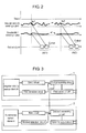
- Fig. 2 illustrates changes in an output signal of the sensor device in the first exemplary embodiment.
- the sensor device includes angular velocity sensor 9 for outputting an angular velocity sensing signal, acceleration sensor 10 for outputting an acceleration sensing signal, and output circuit 19 for outputting the angular velocity sensing signal and the acceleration sensing signal.
- Angular velocity sensor 9 includes drive circuit 11 for outputting a drive signal that drives an angular velocity sensor element, and angular velocity sensor element 12 that receives the drive signal from drive circuit 11.
- Angular velocity sensor 9 also includes detection circuit 13 for taking out a response signal from angular velocity sensor element 12, and first processing circuit 14 that receives a response signal from first detection circuit 13.
- First processing circuit 14 extracts and outputs the angular velocity sensing signal from the response signal.
- Acceleration sensor 10 includes bias circuit 15 for outputting a bias signal, and acceleration sensor element 16 that receives the bias signal. Acceleration sensor 10 also includes second detection circuit 17 for taking out a response signal from acceleration sensor element 16, and second processing circuit 18 that receives a response signal from second detection circuit 17. Second processing circuit 18 extracts and outputs the acceleration sensing signal from the response signal.
- output circuit 19 outputs in a digital format according to the time-division system the angular velocity sensing signal and the acceleration sensing signal detected at ts1 point, i.e., the angular velocity sensing signal and the acceleration sensing signal detected at the same timing, so as to link these signals timewise.
- an A/D converter is provided in output circuit 19, instead of providing it in first and second detection circuits 13 and 17 or first and second processing circuits 14 and 18, a chopper needs to be provided before the A/D converter so as to separate to analog angular velocity signal and analog acceleration signal for output.
- the chopper is not necessarily provided before the A/D converter (not illustrated).
- the angular velocity sensing signal and the acceleration sensing signal can be linked timewise as one signal. This enables accurate correction of the angular velocity sensing signal using the acceleration sensing signal. Accordingly, the detection accuracy of the sensor device can be improved.
- the sensor device corrects the angular velocity sensing signal from angular velocity sensor 9, using gravitational acceleration information included in the acceleration sensing signal from acceleration sensor 10, and detects a spiral travel of the vehicle in the multistory parking lot.
- the sensor device in this exemplary embodiment can accurately correct the angular velocity information based on the gravitational acceleration information from acceleration sensor 10, even if there is a time difference in signal transmission between a circuit of angular velocity sensor 9 and a circuit of acceleration sensor 10. This is because the acceleration sensing signal including the gravitational acceleration information from acceleration sensor 10 and the angular velocity sensing signal from angular velocity sensor 9 are linked timewise. As a result, the detection accuracy of the sensor device can be improved.
- a time difference in signal transmission between the circuit of angular velocity sensor 9 and the circuit of acceleration sensor 10 is calculated. If the signal transmission time in the circuit of angular velocity sensor 9 is shorter than the signal transmission time in the circuit of acceleration sensor 10, a delay circuit is provided in angular velocity sensor 9. Contrarily, if the signal transmission time in the circuit of acceleration sensor 10 is shorter than the signal transmission time in the circuit of angular velocity sensor 9, a delay circuit is provided in acceleration sensor 10.
- the angular velocity sensing signal and the acceleration sensing signal detected at the same timing are input to output circuit 19 at the same timing.
- the angular velocity sensing signal and the acceleration sensing signal detected at the same timing can thus be linked timewise and output as one signal when output circuit 19 sequentially outputs the angular velocity sensing signal and the acceleration sensing signal.
- Another method is to provide a time-point information measurement unit for calculating time-point information, and adding this time-point information to the angular velocity sensing signal and the acceleration sensing signal. Then, output circuit 19 links the angular velocity sensing signal and the acceleration sensing signal having the same time-point information, and outputs these signals as one signal.
Landscapes
- Engineering & Computer Science (AREA)
- Radar, Positioning & Navigation (AREA)
- Remote Sensing (AREA)
- Physics & Mathematics (AREA)
- General Physics & Mathematics (AREA)
- Automation & Control Theory (AREA)
- Gyroscopes (AREA)
- Navigation (AREA)
Abstract
Description
- The present invention relates to sensor devices used in electronic devices and vehicles, including digital cameras and automobile navigation systems.
- As shown in
Fig. 3 , a conventional sensor device includesangular velocity sensor 1 for outputting an angular velocity sensing signal, andacceleration sensor 2 for outputting an acceleration sensing signal. - A prior art related to the present invention is disclosed, for example, in Japanese Patent Unexamined Publication No.
2005-283481 - However, the conventional sensor device has a disadvantage of its low detection accuracy.
- Let's take an example of an automobile navigation system in a vehicle equipped with the above conventional sensor device. More specifically, let's assume that the vehicle is traveling in a multistory parking lot. The sensor device uses gravitational acceleration information from
acceleration sensor 2 for correcting angular velocity information fromangular velocity sensor 1. This enables detection of a spiral travel of the vehicle in the multistory parking lot. - However, in the conventional sensor device, an output on gravitational acceleration from
acceleration sensor 2 and an output onangular velocity sensor 1 are not linked timewise. Accordingly, if there is a difference in signal transmission time between a circuit ofangular velocity sensor 1 and a circuit ofacceleration sensor 2, the angular velocity information cannot be accurately corrected using the gravitational acceleration information fromacceleration sensor 2. This results in low detection accuracy. - An object of the present invention is to improve the detection accuracy of sensor device.
- To achieve this object, the present invention includes an output circuit for outputting an angular velocity sensing signal and an acceleration sensing signal detected at the same timing in a digital format according to the time-division system, so as to link these signals timewise.
- This structure enables output of the angular velocity sensing signal and the acceleration sensing signal linked timewise as one signal. Accordingly, the angular velocity sensing signal can be accurately corrected using the acceleration sensing signal. As a result, the detection accuracy of sensor device improves.
-
-
Fig. 1 is an electrical circuit diagram of an sensor device in accordance with a first exemplary embodiment of the present invention. -
Fig. 2 illustrates changes in an output signal from the sensor device in accordance with the first exemplary embodiment of the present invention. -
Fig. 3 is an electrical circuit diagram of a conventional sensor device. - An sensor device in the first exemplary embodiment is described below with reference to
Figs. 1 and2 .Fig 1 is an electrical circuit diagram of the sensor device in the first exemplary embodiment of the present invention.Fig. 2 illustrates changes in an output signal of the sensor device in the first exemplary embodiment. - In
Fig. 1 , the sensor device includesangular velocity sensor 9 for outputting an angular velocity sensing signal,acceleration sensor 10 for outputting an acceleration sensing signal, andoutput circuit 19 for outputting the angular velocity sensing signal and the acceleration sensing signal. -
Angular velocity sensor 9 includesdrive circuit 11 for outputting a drive signal that drives an angular velocity sensor element, and angularvelocity sensor element 12 that receives the drive signal fromdrive circuit 11.Angular velocity sensor 9 also includesdetection circuit 13 for taking out a response signal from angularvelocity sensor element 12, andfirst processing circuit 14 that receives a response signal fromfirst detection circuit 13.First processing circuit 14 extracts and outputs the angular velocity sensing signal from the response signal. -
Acceleration sensor 10 includesbias circuit 15 for outputting a bias signal, andacceleration sensor element 16 that receives the bias signal.Acceleration sensor 10 also includessecond detection circuit 17 for taking out a response signal fromacceleration sensor element 16, andsecond processing circuit 18 that receives a response signal fromsecond detection circuit 17.Second processing circuit 18 extracts and outputs the acceleration sensing signal from the response signal. - In the sensor device in this exemplary embodiment, as shown in
Fig. 2 ,output circuit 19 outputs in a digital format according to the time-division system the angular velocity sensing signal and the acceleration sensing signal detected at ts1 point, i.e., the angular velocity sensing signal and the acceleration sensing signal detected at the same timing, so as to link these signals timewise. - If an A/D converter is provided in
output circuit 19, instead of providing it in first andsecond detection circuits second processing circuits - If the A/D converter (not illustrated) is provided in first and
second detection circuits second processing circuits - With this structure, the angular velocity sensing signal and the acceleration sensing signal can be linked timewise as one signal. This enables accurate correction of the angular velocity sensing signal using the acceleration sensing signal. Accordingly, the detection accuracy of the sensor device can be improved.
- Next is described an example of an automobile navigation system in a vehicle equipped with the sensor device in the first exemplary embodiment. Let's say this vehicle is traveling in a multistory parking lot. The sensor device corrects the angular velocity sensing signal from
angular velocity sensor 9, using gravitational acceleration information included in the acceleration sensing signal fromacceleration sensor 10, and detects a spiral travel of the vehicle in the multistory parking lot. On detecting this spiral travel, the sensor device in this exemplary embodiment can accurately correct the angular velocity information based on the gravitational acceleration information fromacceleration sensor 10, even if there is a time difference in signal transmission between a circuit ofangular velocity sensor 9 and a circuit ofacceleration sensor 10. This is because the acceleration sensing signal including the gravitational acceleration information fromacceleration sensor 10 and the angular velocity sensing signal fromangular velocity sensor 9 are linked timewise. As a result, the detection accuracy of the sensor device can be improved. - Next is described a specific method of linking timewise the angular velocity sensing signal and the acceleration velocity sensing signal detected at the same timing, and outputting these signals as one signal.
- First, a time difference in signal transmission between the circuit of
angular velocity sensor 9 and the circuit ofacceleration sensor 10 is calculated. If the signal transmission time in the circuit ofangular velocity sensor 9 is shorter than the signal transmission time in the circuit ofacceleration sensor 10, a delay circuit is provided inangular velocity sensor 9. Contrarily, if the signal transmission time in the circuit ofacceleration sensor 10 is shorter than the signal transmission time in the circuit ofangular velocity sensor 9, a delay circuit is provided inacceleration sensor 10. - With this structure, the angular velocity sensing signal and the acceleration sensing signal detected at the same timing are input to
output circuit 19 at the same timing. The angular velocity sensing signal and the acceleration sensing signal detected at the same timing can thus be linked timewise and output as one signal whenoutput circuit 19 sequentially outputs the angular velocity sensing signal and the acceleration sensing signal. - Another method is to provide a time-point information measurement unit for calculating time-point information, and adding this time-point information to the angular velocity sensing signal and the acceleration sensing signal. Then,
output circuit 19 links the angular velocity sensing signal and the acceleration sensing signal having the same time-point information, and outputs these signals as one signal.
Claims (5)
- An sensor device comprising:an angular velocity sensor for outputting an angular velocity sensing signal;an acceleration sensor for outputting an acceleration sensing signal; andan output circuit for outputting the angular velocity sensing signal and the acceleration sensing signal;wherein
the output circuit outputs in a digital format according to a time-division system, the output circuit linking the angular velocity sensing signal and the acceleration sensing signal detected at the same timing. - The sensor device of claim 1, wherein the angular velocity sensor includes:a drive circuit for outputting a drive signal that drives an angular velocity sensor element;the angular velocity sensor element for receiving the drive signal from the drive circuit;a first detection circuit for taking a response signal from the angular velocity sensor element; anda first processing circuit for receiving a response signal from the first detection circuit, the first processing circuit extracting and outputting the angular velocity sensing signal from the response signal.
- The sensor device of claim 1, wherein the acceleration sensor includes:a bias circuit for outputting a bias signal;an acceleration sensor element for receiving the bias signal:a second detection circuit for taking a response signal from the acceleration sensor element; anda second processing circuit for receiving a response signal from the second detection circuit, the second processing circuit extracting and outputting the acceleration sensing signal from the response signal.
- The sensor device of claim 1, wherein a delay circuit is provided in one of the angular velocity sensor and the acceleration sensor.
- The sensor device of claim 1, wherein the output circuit links timewise the angular velocity sensing signal and the acceleration sensing signal, and outputs as one signal.
Applications Claiming Priority (1)
| Application Number | Priority Date | Filing Date | Title |
|---|---|---|---|
| JP2008323685A JP2010145274A (en) | 2008-12-19 | 2008-12-19 | Inertial sensor |
Publications (2)
| Publication Number | Publication Date |
|---|---|
| EP2199744A2 true EP2199744A2 (en) | 2010-06-23 |
| EP2199744A3 EP2199744A3 (en) | 2011-04-06 |
Family
ID=41566433
Family Applications (1)
| Application Number | Title | Priority Date | Filing Date |
|---|---|---|---|
| EP09178581A Ceased EP2199744A3 (en) | 2008-12-19 | 2009-12-10 | Sensor Device |
Country Status (5)
| Country | Link |
|---|---|
| US (1) | US8276448B2 (en) |
| EP (1) | EP2199744A3 (en) |
| JP (1) | JP2010145274A (en) |
| KR (1) | KR20100071927A (en) |
| CN (1) | CN101750510A (en) |
Families Citing this family (7)
| Publication number | Priority date | Publication date | Assignee | Title |
|---|---|---|---|---|
| US9008757B2 (en) | 2012-09-26 | 2015-04-14 | Stryker Corporation | Navigation system including optical and non-optical sensors |
| JP2014149218A (en) * | 2013-02-01 | 2014-08-21 | Hitachi Automotive Systems Ltd | Inertial force detection device |
| CN105580278B (en) * | 2013-09-22 | 2018-10-19 | 瑞典爱立信有限公司 | Self-adapting compensation method in PLL and PLL |
| CN107636473B (en) * | 2015-05-20 | 2020-09-01 | 卢米达因科技公司 | Extracting inertial information from non-linear periodic signals |
| US10316884B2 (en) | 2015-06-18 | 2019-06-11 | Matthew C. Prestwich | Motion activated switch and method |
| DE102017221868A1 (en) | 2017-12-05 | 2019-06-06 | BSH Hausgeräte GmbH | Household appliance with sensor for detecting a door movement |
| CN112611883A (en) * | 2020-12-04 | 2021-04-06 | 北京融智世纪节能技术服务有限公司 | Synchronous measuring method for rotating speed signals |
Citations (1)
| Publication number | Priority date | Publication date | Assignee | Title |
|---|---|---|---|---|
| US20040064252A1 (en) | 2002-09-26 | 2004-04-01 | Honeywell International Inc. | Method and system for processing pulse signals within an inertial navigation system |
Family Cites Families (20)
| Publication number | Priority date | Publication date | Assignee | Title |
|---|---|---|---|---|
| JPH0672899B2 (en) * | 1988-04-01 | 1994-09-14 | 株式会社日立製作所 | Acceleration sensor |
| JPH07239236A (en) | 1994-02-28 | 1995-09-12 | Hitachi Ltd | Method and apparatus for measurement of quantity of state of moving body and calculation device of attitude angle of moving body |
| US5935191A (en) * | 1994-11-08 | 1999-08-10 | Matsushita Electric Industrial Co., Ltd. | Navigation apparatus for a vehicle |
| CN1160574C (en) | 1995-05-30 | 2004-08-04 | 松下电器产业株式会社 | Angular-rate sensor |
| JP3272960B2 (en) * | 1996-08-19 | 2002-04-08 | 株式会社データ・テック | Driving recorder and vehicle operation analyzer |
| DE19827688A1 (en) * | 1997-06-20 | 1999-01-28 | Aisin Seiki | Angular velocity sensor |
| JPH11248456A (en) * | 1998-02-27 | 1999-09-17 | Olympus Optical Co Ltd | Three-axial attitude detecting device |
| US6584845B1 (en) * | 1999-02-10 | 2003-07-01 | California Institute Of Technology | Inertial sensor and method of use |
| JP2002252850A (en) * | 2001-02-26 | 2002-09-06 | Matsushita Electric Ind Co Ltd | Experimental result management system and experimental result management method |
| JP2002329281A (en) * | 2001-05-01 | 2002-11-15 | Tokyo Gas Co Ltd | Method and apparatus for managing measured data |
| JP4881517B2 (en) * | 2001-07-12 | 2012-02-22 | マイクロストーン株式会社 | Physical condition monitoring device |
| US7021140B2 (en) * | 2001-07-24 | 2006-04-04 | Noel C. Perkins | Electronic measurement of the motion of a moving body of sports equipment |
| US7243561B2 (en) * | 2003-08-26 | 2007-07-17 | Matsushita Electric Works, Ltd. | Sensor device |
| JP4645013B2 (en) | 2003-10-03 | 2011-03-09 | パナソニック株式会社 | Acceleration sensor and composite sensor using the same |
| US7028546B2 (en) * | 2003-10-21 | 2006-04-18 | Instrumented Sensor Technology, Inc. | Data recorder |
| JP2005274457A (en) * | 2004-03-25 | 2005-10-06 | Denso Corp | Acceleration sensor system |
| JP2005283481A (en) * | 2004-03-30 | 2005-10-13 | Denso Corp | Sensor system |
| KR100651549B1 (en) * | 2005-05-13 | 2007-02-28 | 삼성전자주식회사 | Method and apparatus for measuring speed of land vehicle |
| US7730782B2 (en) * | 2008-04-04 | 2010-06-08 | Panasonic Corporation | Sensor device |
| JP2010145273A (en) * | 2008-12-19 | 2010-07-01 | Panasonic Corp | Sensor device |
-
2008
- 2008-12-19 JP JP2008323685A patent/JP2010145274A/en active Pending
-
2009
- 2009-12-07 US US12/632,066 patent/US8276448B2/en active Active
- 2009-12-10 EP EP09178581A patent/EP2199744A3/en not_active Ceased
- 2009-12-18 KR KR1020090126834A patent/KR20100071927A/en not_active Application Discontinuation
- 2009-12-21 CN CN200910259406A patent/CN101750510A/en active Pending
Patent Citations (1)
| Publication number | Priority date | Publication date | Assignee | Title |
|---|---|---|---|---|
| US20040064252A1 (en) | 2002-09-26 | 2004-04-01 | Honeywell International Inc. | Method and system for processing pulse signals within an inertial navigation system |
Non-Patent Citations (1)
| Title |
|---|
| KOUROGI M ET AL: "A method of personal positioning based on sensor data fusion of wearable camera and self-contained sensors", MULTISENSOR FUSION AND INTEGRATION FOR INTELLIGENT SYSTEMS, MFI2003. P ROCEEDINGS OF IEEE INTERNATIONAL CONFERENCE ON JULY 30-AUG. 1, 2003, PISCATAWAY, NJ, USA,IEEE, 30 July 2003 (2003-07-30), pages 287 - 292, XP010658336, ISBN: 978-0-7803-7987-9 * |
Also Published As
| Publication number | Publication date |
|---|---|
| KR20100071927A (en) | 2010-06-29 |
| EP2199744A3 (en) | 2011-04-06 |
| CN101750510A (en) | 2010-06-23 |
| US20100154540A1 (en) | 2010-06-24 |
| JP2010145274A (en) | 2010-07-01 |
| US8276448B2 (en) | 2012-10-02 |
Similar Documents
| Publication | Publication Date | Title |
|---|---|---|
| US8276448B2 (en) | Sensor device with timewise linked sensing signals | |
| US8393213B2 (en) | Sensor device | |
| KR100277119B1 (en) | Velocity calculating apparatus | |
| US9269269B2 (en) | Blind spot warning system and method | |
| CN101065683B (en) | Error compensation method for a 3D camera | |
| EP2549458A1 (en) | Vehicle orientation angle calculating device, and lane deviation warning system using same | |
| US8131507B2 (en) | Sensor apparatus | |
| US7775109B2 (en) | Sensor device | |
| EP1862777A3 (en) | System and method for adjusting offset compensation applied to a signal | |
| KR100740577B1 (en) | electric train A.T.O. system and it's materialization method | |
| KR100972077B1 (en) | Sensor device | |
| US8131508B2 (en) | Sensor apparatus | |
| EP1884907A1 (en) | Vehicle and lane mark recognizer | |
| JP4808131B2 (en) | Stop determination method | |
| PH12019000095A1 (en) | Method and apparatus for compensating air data using inertial navigation data | |
| US20150211856A1 (en) | Apparatus for driving gyro sensor and control method thereof | |
| EP2284489A1 (en) | Sensor device | |
| JP2005329765A (en) | Run lane recognition device | |
| JP2010096602A (en) | Sensor device | |
| JPH10332719A (en) | Speed measuring device | |
| CN112305263A (en) | Acceleration signal measuring method and device based on inertial sensor | |
| KR20050075843A (en) | Gyro sensor integrated navigation system and controlling method for the same | |
| JP2006284319A (en) | Current position calculation system and current position calculation method |
Legal Events
| Date | Code | Title | Description |
|---|---|---|---|
| PUAI | Public reference made under article 153(3) epc to a published international application that has entered the european phase |
Free format text: ORIGINAL CODE: 0009012 |
|
| AK | Designated contracting states |
Kind code of ref document: A2 Designated state(s): AT BE BG CH CY CZ DE DK EE ES FI FR GB GR HR HU IE IS IT LI LT LU LV MC MK MT NL NO PL PT RO SE SI SK SM TR |
|
| AX | Request for extension of the european patent |
Extension state: AL BA RS |
|
| PUAL | Search report despatched |
Free format text: ORIGINAL CODE: 0009013 |
|
| AK | Designated contracting states |
Kind code of ref document: A3 Designated state(s): AT BE BG CH CY CZ DE DK EE ES FI FR GB GR HR HU IE IS IT LI LT LU LV MC MK MT NL NO PL PT RO SE SI SK SM TR |
|
| AX | Request for extension of the european patent |
Extension state: AL BA RS |
|
| RIC1 | Information provided on ipc code assigned before grant |
Ipc: G01C 21/16 20060101ALI20110225BHEP Ipc: H04N 5/232 20060101ALI20110225BHEP Ipc: G01C 21/12 20060101AFI20100129BHEP |
|
| 17P | Request for examination filed |
Effective date: 20111006 |
|
| 17Q | First examination report despatched |
Effective date: 20111111 |
|
| STAA | Information on the status of an ep patent application or granted ep patent |
Free format text: STATUS: THE APPLICATION HAS BEEN REFUSED |
|
| 18R | Application refused |
Effective date: 20130225 |