EP2199627B1 - Ensemble de rivet aveugle - Google Patents
Ensemble de rivet aveugle Download PDFInfo
- Publication number
- EP2199627B1 EP2199627B1 EP09179372.9A EP09179372A EP2199627B1 EP 2199627 B1 EP2199627 B1 EP 2199627B1 EP 09179372 A EP09179372 A EP 09179372A EP 2199627 B1 EP2199627 B1 EP 2199627B1
- Authority
- EP
- European Patent Office
- Prior art keywords
- stem
- shell
- head
- blind
- ring
- Prior art date
- Legal status (The legal status is an assumption and is not a legal conclusion. Google has not performed a legal analysis and makes no representation as to the accuracy of the status listed.)
- Not-in-force
Links
- 238000009434 installation Methods 0.000 claims description 20
- 239000000463 material Substances 0.000 claims description 4
- 229910000831 Steel Inorganic materials 0.000 description 1
- 229910052782 aluminium Inorganic materials 0.000 description 1
- XAGFODPZIPBFFR-UHFFFAOYSA-N aluminium Chemical compound [Al] XAGFODPZIPBFFR-UHFFFAOYSA-N 0.000 description 1
- 230000000712 assembly Effects 0.000 description 1
- 238000000429 assembly Methods 0.000 description 1
- 230000000694 effects Effects 0.000 description 1
- 238000003780 insertion Methods 0.000 description 1
- 230000037431 insertion Effects 0.000 description 1
- 230000014759 maintenance of location Effects 0.000 description 1
- 229910052751 metal Inorganic materials 0.000 description 1
- 239000002184 metal Substances 0.000 description 1
- 238000000034 method Methods 0.000 description 1
- 239000007787 solid Substances 0.000 description 1
- 229910001220 stainless steel Inorganic materials 0.000 description 1
- 239000010935 stainless steel Substances 0.000 description 1
- 239000010959 steel Substances 0.000 description 1
Images
Classifications
-
- F—MECHANICAL ENGINEERING; LIGHTING; HEATING; WEAPONS; BLASTING
- F16—ENGINEERING ELEMENTS AND UNITS; GENERAL MEASURES FOR PRODUCING AND MAINTAINING EFFECTIVE FUNCTIONING OF MACHINES OR INSTALLATIONS; THERMAL INSULATION IN GENERAL
- F16B—DEVICES FOR FASTENING OR SECURING CONSTRUCTIONAL ELEMENTS OR MACHINE PARTS TOGETHER, e.g. NAILS, BOLTS, CIRCLIPS, CLAMPS, CLIPS OR WEDGES; JOINTS OR JOINTING
- F16B19/00—Bolts without screw-thread; Pins, including deformable elements; Rivets
- F16B19/04—Rivets; Spigots or the like fastened by riveting
- F16B19/08—Hollow rivets; Multi-part rivets
- F16B19/10—Hollow rivets; Multi-part rivets fastened by expanding mechanically
- F16B19/1027—Multi-part rivets
- F16B19/1036—Blind rivets
Definitions
- the present invention relates generally to blind rivet assemblies, and particularly to a blind rivet which will operate in workpieces to be fastened together and will become radially expanded in order to provide hole fill and an interference fit with the surfaces of the openings of the workpieces upon final installation, and clamp the workpieces together.
- the installed fastener has the capability of withstanding high shear loads.
- the magnitude of the clamp load is established by the relative axial force applied between the stem and shell when the blind head is formed and then engages the back surface of the workpiece.
- the magnitude of the shear load is primarily determined in this type of rivet by the mechanical strength of the stem, while the shear strength which can be attributed to the shell is normally less significant, and cannot be readily increased, since the shell must retain high ductility in order to be deformed during setting.
- Patent document US 5,346,348 discloses a blind rivet assembly with an elongate stem and a headed tubular body.
- Patent document US 6,077,009 discloses a blind rivet assembly with high strength blind head and high clamp and high shear load resistance.
- Patent document US 3,292,482 discloses a self-plugging blind rivet type fastening device with a tubular rivet with a head at one end and a mandrel having a head which is drawn into the rivet to effect placement thereof in work pieces to be fastened together.
- the above-described problem is solved by the features of claim 1, which allows the stem to plug the workpiece and provide high shear strength, while at the same time allowing the rivet to be used in multiple applications and workpiece widths.
- the first blind head is formed in the shell by a placement ring.
- the ring is assembled onto the stem shank, located under the stem head, and is moved into the blind end of the shell in response to an axial force applied to the stem by the installation tool. This force inserts the ring into the blind end of the shell, thereby deforming the shell and forming a blind head. This deformation engages the inner (rear) workpiece surface and initiates a clamping of the workpieces.
- the ring is moved fully into the shell to further increase the clamp load, and the ring will progress into the shell until the point where it meets the rear side of the workpiece and cannot progress any further.
- the stem head Concurrently with, or subsequent to, the insertion of the ring inside the shell, the stem head is moved into the blind end of the shell and radially expands the shell further.
- the stem shank is moved to a final position where a lock is engaged to lock the stem and shell together, and at which position a break-groove on the stem is now in line with the shell head.
- the stem will shear and installation is complete.
- the placement ring, shell and stem are designed such that the rivet will allow a wide range of workpiece widths ("grip ranges") to be used using one fastener.
- grip ranges workpiece widths
- the stem head At a minimum workpiece width, the stem head will remain either outside the ring altogether, or only enter it minimally.
- the stem head At a maximum width of the workpiece, the stem head will enter the ring quite deeply, typically entering more than 3/4 of the length of the ring. Therefore, the placement ring is the component which allows the stem, with its break-groove at a given location, to always shear at the top of the shell head, thereby allowing the stem to fully plug the workpiece and provide high shear strength.
- a three piece blind rivet assembly which includes a tubular shell, a stem and a hollow placement ring.
- the rivet is designed to secure a variety of workpieces while forming a high strength fastening.
- the stem has a shank which extends through the tubular shell, and an enlarged head under which the hollow placement ring is initially located.
- a groove located in the stem accepts excess material from the shell which is displaced during the setting process and serves to lock the assembly in place.
- the stem shank can be gripped and pulled by an installation tool, and the movement of the stem will force the placement ring to move into the blind end of the tubular shell. This will form a blind head through deformation of the shell, for clamping workpieces together.
- the stem head is then forced into the blind end of the shell, creating additional deformation of the shell, and the stem will shear at a pre-determined point which will be located adjacent to the head of the shell.
- blind rivet is exemplary in nature and in no way is intended to limit the invention or its applications.
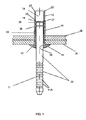
- a blind rivet is shown and includes a tubular shell 10, a stem 11 and a placement ring 12 in assembled condition, prior to installation.
- the rivet is shown placed in workpieces 20 and 21, which are to be fastened together.
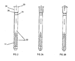
- the stem 11 has an elongated shank 22 partly grooved, which terminates in an enlarged stem head 23. Under the head is a portion 24 of the shank upon which the placement ring is assembled.
- a lock-groove 25 and break-groove 26 are located at pre-determined locations.
- the lock-groove has a diameter designed to allow material from the shell 10 to flow inside the groove during installation, and the break-groove 26 is the weakest section of the stem and will shear at the conclusion of the installation.
- Fig. 2A and 2B show other configurations for the stem, namely different head shapes and a bore in the stem head to allow the head to enter the placement ring easier. Other varieties of stem and other locking systems are possible.
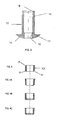
- the shell 10 has a shank of uniform diameter and an enlarged head 14.
- the shell has a through bore 15 in the shank, with a head bore 16 of a reduced diameter.
- a stop shoulder 17 is located at the juncture of the two bores 15 and 16.
- a countersunk chamfer 18 at the blind end of the shell allows the stem and ring to enter the shell with less force.
- the placement ring 12 is located under the stem head. Its outer diameter and bore are designed to sufficiently deform the shell 10 during installation, and to allow the stem 11 to move in the designed manner during installation at various workpiece widths.
- Placement ring 12 has a near end 35 and a far end 37.
- a chamfer 27 is located at the edge of the ring which will first enter the shell 10, that is, the near end 35, in order to allow easy entry.
- Fig. 4A, 4B and 4C show other configurations for the placement ring, with the possibility of two bore sizes, an enlarged head, a version without chamfer 27 ( Fig. 4B ), and any combination of these or other versions which can be considered.
- the rivet is designed to be set by standard rivet installation tools, wherein the tool engages gripping means, e.g., stem pull grooves 11A ( Fig. 1 ), while an anvil engages the shell head 14, which is in contact with the outer workpiece 21.
- gripping means e.g., stem pull grooves 11A ( Fig. 1 )
- anvil engages the shell head 14, which is in contact with the outer workpiece 21.
- axial force is applied between the stem, shell and ring, to move the stem 11 and ring 12 into the shell 10.
- the movement of the stem 11 and ring 12 continues until the placement ring 12 is located at a position proximate to the rear side of workpiece 20, and cannot progress any further due to shell 10 deforming outwards and forming a blind shoulder that abuts against the blind side of the workpieces near the near end 35 of placement ring 12.
- the relative axial load applied to stem 11 and shell 10 clamps workpieces 20 and 21 together at a preselected amount of load. This movement of the ring 12 will cause some deformation thereof.
- the stem 11 As the magnitude of axial force increases, the stem 11 progressively moves into the shell 10, and creates further deformation of the ring 12. This movement will continue until the stem 11 encounters the shell stop shoulder 17. At this point, the material of the shell stop shoulder 17 will be moved by the stem 11 into the stem lock-groove 25, after which further movement of the stem 11 will be stopped. Now, the amount of relative axial force will increase to a point at which the stem shank 22 will be sheared at the break- groove 26 and installation is complete.
- the stem 11 has a "locking skirt" which is operated by a special nosepiece on the installation tool, and which provides the same desirable function of locking stem 11 and shell 10 together.
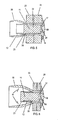
- Fig. 5 and Fig. 6 show the rivet in the final installed orientation, with Fig. 6 showing "minimum grip” (or workpiece width) orientation and Fig. 5 showing “maximum grip” (or workpiece width) orientation.
- minimum grip orientation Fig. 6
- maximum grip orientation Fig. 5
- stem head 23 has entered deeply into the ring 12, typically entering more than half the length of the ring 12. It is this large range of movement by the stem 11 inside the placement ring 12, which allows this rivet to be used in a wide variety of "grips" or workpiece widths.
- the "grip range" of this blind rivet can be selectively varied by providing a longer or shorter shell 10, and/or a longer or shorter placement ring 12 in combination with a longer section of stem shank 24.
- the close engagement between the placement ring 12 and the inner surface of the shell bore 15 provides additional resistance to stem push-out, while supporting clamp retention.
- the expanded portion of the shell shank 30 will spring back to partially grip ring 12 (as indicated by arrows 41 in Fig. 6 ) and thereby enhance the strength of the clamp and lock of the installed rivet.
- the invention can work with various metal types, including but not limited to aluminum, steel and stainless steel.
- Another embodiment includes additional locking features, including various grooves which can be located on each of the three components, and which provide resistance to stem push-out.
Landscapes
- Engineering & Computer Science (AREA)
- General Engineering & Computer Science (AREA)
- Mechanical Engineering (AREA)
- Insertion Pins And Rivets (AREA)
Claims (2)
- Ensemble de rivet aveugle pour assujettir des pièces à travailler (20, 21) ayant des perçages alignés, dans lequel lesdites pièces à travailler (20, 21) ont une surface ouverte sur un côté ouvert et une surface aveugle sur un côté aveugle, ledit ensemble de rivet aveugle comprenant :une enveloppe tubulaire (10) ayant une tête d'enveloppe (14) élargie adaptée pour être en prise avec la surface ouverte des pièces (20, 21), ladite enveloppe (10) étant adaptée pour s'étendre à travers les perçages de pièce à travailler et ayant une section de tête aveugle située sur ladite surface aveugle des pièces à travailler (20, 21), ladite enveloppe tubulaire (10) étant formée avec un trou débouchant (15) s'étendant vers ladite tête d'enveloppe (14) élargie et avec un perçage de tête (16) à travers ladite tête d'enveloppe (14) élargie, qui a un diamètre inférieur à celui du trou débouchant (15), dans lequel un épaulement de butée (17) est situé sur un point de jonction dudit trou débouchant (15) etdudit perçage de tête (16) ;une tige (11) disposée dans ledit trou débouchant (15) et ledit perçage de tête (16), ladite tige (11) ayant une queue (22) allongée avec une tête de tige (23) à une extrémité aveugle de ladite queue (22) et ayant des moyens de préhension à l'extrémité opposée qui sont adaptés pour être pris par un outil d'installation pour appliquer une force de traction axiale, à proximité de ladite tête de tige (23) étant située une portion de réception d'anneau (24) de ladite queue (22) allongée, et à proximité de ladite portion de réception d'anneau (24) sur la queue (22) allongée se trouvant une portion de blocage (25), et à proximité de ladite portion de blocage (25) sur la queue (22) allongée étant située une rainure de rupture (26) apte à être cisaillée ; etun anneau de positionnement (12) ayant une extrémité proche (35) et une extrémité distante (37) et ayant une orientation de pré-installation et une orientation de post-installation, dans lequel, dans l'orientation de pré-installation, ledit anneau de positionnement (12) est disposé autour de ladite portion de réception d'anneau (24) de ladite queue (22) allongée, etl'orientation de post-installation est créée en tirant axialement ladite tige (11) vers le côté ouvert des pièces à travailler (20, 21) au moyen d'une force de traction axiale qui force ledit anneau de positionnement (12) dans ledit trou débouchant (15) ce par quoi ladite enveloppe (10) est déformée vers l'extérieur et forme une tête aveugle, ledit anneau de positionnement (12) et ladite tige (11) se déplaçant ainsi jusqu'à ce que ladite extrémité proche (35) de l'anneau de positionnement (12) soit située sur une position à proximité du côté aveugle des pièces à travailler (20, 21) et ledit anneau de positionnement (12) ne puisse pas avancer encore plus dû au fait que ladite enveloppe (10) est déformée vers l'extérieur et forme un épaulement aveugle qui vient en appui contre le côté aveugle des pièces à travailler (20, 21) à proximité de ladite extrémité proche (35) de l'anneau de positionnement (12), et, en continuant à tirer axialement ladite tige (11), la tige (11) se déplacé progressivement dans ladite enveloppe (10) jusqu'à ce que ladite tige (11) rencontre ledit épaulement de butée (17), ce après quoi de la matière de l'épaulement de butée (17) est mue dans la portion de blocage (25) de manière à arrêter un autre mouvement de la tige (11), et ce sur quoi une force axiale plus importante sur ladite tige (11) provoque le cisaillement d'une portion de la tige (11) sur le côte ouvert sur ladite rainure de rupture (26) apte à être cisaillée,dans lequel l'orientation de post-installation comprend une orientation de préhension minimale et une orientation de préhension maximale, dans ladite orientation de préhension minimale, la tête de tige (23) restant au moins en partie à l'extérieur de l'anneau de positionnement (12), tandis que, dans ladite orientation de préhension maximale, la tête de tige (23) entrant complètement dans ledit anneau de positionnement (12), etdans lequel, dans ladite orientation de préhension maximale, une portion évasée de ladite enveloppe (10) rebondit afin de prendre partiellement ledit anneau de positionnement (12).
- Ensemble de rivet aveugle selon la revendication 1, dans lequel, dans ladite orientation de préhension maximale, la tête de tige (23) entre au moins dans la moitié de la longueur de l'anneau de positionnement (12).
Applications Claiming Priority (1)
| Application Number | Priority Date | Filing Date | Title |
|---|---|---|---|
| US12275008P | 2008-12-16 | 2008-12-16 |
Publications (3)
| Publication Number | Publication Date |
|---|---|
| EP2199627A2 EP2199627A2 (fr) | 2010-06-23 |
| EP2199627A3 EP2199627A3 (fr) | 2012-03-28 |
| EP2199627B1 true EP2199627B1 (fr) | 2014-11-19 |
Family
ID=42041858
Family Applications (1)
| Application Number | Title | Priority Date | Filing Date |
|---|---|---|---|
| EP09179372.9A Not-in-force EP2199627B1 (fr) | 2008-12-16 | 2009-12-16 | Ensemble de rivet aveugle |
Country Status (3)
| Country | Link |
|---|---|
| US (1) | US8029220B2 (fr) |
| EP (1) | EP2199627B1 (fr) |
| ES (1) | ES2530880T3 (fr) |
Families Citing this family (7)
| Publication number | Priority date | Publication date | Assignee | Title |
|---|---|---|---|---|
| CN103379846B (zh) | 2010-12-17 | 2016-08-10 | 碧美斯制造公司 | 马桶座圈铰接组件 |
| EP3155945B1 (fr) | 2011-03-11 | 2018-09-05 | Bemis Manufacturing Company | Ensemble de charnière de siège de toilettes |
| CA2908220C (fr) * | 2013-09-19 | 2017-06-27 | Alcoa Inc. | Rivet |
| JP2018524177A (ja) | 2015-06-03 | 2018-08-30 | ダイムラー・アクチェンゲゼルシャフトDaimler AG | フロー成形リベットスリーブを使用して少なくとも2つの部品を接合するための方法及び接合要素 |
| GB2541248B (en) * | 2015-08-14 | 2017-08-16 | Avdel Uk Ltd | Rivets |
| US10285546B2 (en) | 2017-02-13 | 2019-05-14 | Topseat International, Inc. | System and method for removably mounting toilet seat to toilet bowl |
| CN108799293A (zh) * | 2018-07-13 | 2018-11-13 | 航天精工股份有限公司 | 一种带剪切环的抽芯铆钉 |
Citations (2)
| Publication number | Priority date | Publication date | Assignee | Title |
|---|---|---|---|---|
| US3292482A (en) * | 1963-08-30 | 1966-12-20 | Avdel Ltd | Self-plugging blind fastening device |
| GB2127514A (en) * | 1982-09-28 | 1984-04-11 | Huck Mfg Co | Two piece blind fastener |
Family Cites Families (7)
| Publication number | Priority date | Publication date | Assignee | Title |
|---|---|---|---|---|
| US3369289A (en) * | 1964-11-27 | 1968-02-20 | Textron Ind Inc | Die-draw blind rivet with deformable die and the method of setting same |
| GB1145124A (en) * | 1965-08-12 | 1969-03-12 | Avdel Ltd | Fastening devices |
| GB2269873A (en) | 1992-08-21 | 1994-02-23 | Avdel Systems Ltd | Self-plugging blind fastener |
| US5429464A (en) * | 1994-02-16 | 1995-07-04 | Textron Inc. | Blind fastener with two-piece expander |
| US5569006A (en) * | 1995-05-11 | 1996-10-29 | Textron, Inc. | Bulb fastener |
| US6077009A (en) * | 1999-04-09 | 2000-06-20 | Huck International, Inc. | Blind fastener with high strength blind head and high clamp and high shear load resistance |
| US20030123947A1 (en) * | 2001-12-27 | 2003-07-03 | Soheil Eshraghi | Blind rivet with hollow head |
-
2009
- 2009-12-15 US US12/637,790 patent/US8029220B2/en not_active Expired - Fee Related
- 2009-12-16 ES ES09179372T patent/ES2530880T3/es active Active
- 2009-12-16 EP EP09179372.9A patent/EP2199627B1/fr not_active Not-in-force
Patent Citations (2)
| Publication number | Priority date | Publication date | Assignee | Title |
|---|---|---|---|---|
| US3292482A (en) * | 1963-08-30 | 1966-12-20 | Avdel Ltd | Self-plugging blind fastening device |
| GB2127514A (en) * | 1982-09-28 | 1984-04-11 | Huck Mfg Co | Two piece blind fastener |
Also Published As
| Publication number | Publication date |
|---|---|
| US20100150681A1 (en) | 2010-06-17 |
| US8029220B2 (en) | 2011-10-04 |
| ES2530880T3 (es) | 2015-03-06 |
| EP2199627A2 (fr) | 2010-06-23 |
| EP2199627A3 (fr) | 2012-03-28 |
Similar Documents
| Publication | Publication Date | Title |
|---|---|---|
| EP2199627B1 (fr) | Ensemble de rivet aveugle | |
| CA2351467C (fr) | Fixation aveugle | |
| US8517649B2 (en) | Dual-action disposable clamp | |
| US9464654B2 (en) | Fastener and method of installing same | |
| EP2647851B1 (fr) | Élément de fixation et son procédé d'installation | |
| EP3150866B1 (fr) | Boulon de blocage | |
| US20110123289A1 (en) | Blind fastener | |
| JP2005514566A5 (fr) | ||
| US7722303B2 (en) | Frangible blind rivet | |
| US5810530A (en) | Interference blind type bolt | |
| EP1327082B1 (fr) | Fixation en aveugle | |
| CN111771065B (zh) | 定位紧固件及其安装方法 | |
| US9903403B2 (en) | Fastener and method of installing same | |
| US5697141A (en) | Method of securing members together | |
| EP0728950A1 (fr) | Procédé pour la fixation de deux éléments et dispositif de fixation associé | |
| EP0718508A2 (fr) | Rivet aveugle |
Legal Events
| Date | Code | Title | Description |
|---|---|---|---|
| PUAI | Public reference made under article 153(3) epc to a published international application that has entered the european phase |
Free format text: ORIGINAL CODE: 0009012 |
|
| AK | Designated contracting states |
Kind code of ref document: A2 Designated state(s): AT BE BG CH CY CZ DE DK EE ES FI FR GB GR HR HU IE IS IT LI LT LU LV MC MK MT NL NO PL PT RO SE SI SK SM TR |
|
| AX | Request for extension of the european patent |
Extension state: AL BA RS |
|
| PUAL | Search report despatched |
Free format text: ORIGINAL CODE: 0009013 |
|
| AK | Designated contracting states |
Kind code of ref document: A3 Designated state(s): AT BE BG CH CY CZ DE DK EE ES FI FR GB GR HR HU IE IS IT LI LT LU LV MC MK MT NL NO PL PT RO SE SI SK SM TR |
|
| AX | Request for extension of the european patent |
Extension state: AL BA RS |
|
| RIC1 | Information provided on ipc code assigned before grant |
Ipc: F16B 19/10 20060101AFI20120220BHEP |
|
| 17P | Request for examination filed |
Effective date: 20120919 |
|
| 17Q | First examination report despatched |
Effective date: 20121205 |
|
| GRAP | Despatch of communication of intention to grant a patent |
Free format text: ORIGINAL CODE: EPIDOSNIGR1 |
|
| INTG | Intention to grant announced |
Effective date: 20140514 |
|
| GRAS | Grant fee paid |
Free format text: ORIGINAL CODE: EPIDOSNIGR3 |
|
| RAP1 | Party data changed (applicant data changed or rights of an application transferred) |
Owner name: SARIV S.R.L. |
|
| GRAA | (expected) grant |
Free format text: ORIGINAL CODE: 0009210 |
|
| AK | Designated contracting states |
Kind code of ref document: B1 Designated state(s): AT BE BG CH CY CZ DE DK EE ES FI FR GB GR HR HU IE IS IT LI LT LU LV MC MK MT NL NO PL PT RO SE SI SK SM TR |
|
| REG | Reference to a national code |
Ref country code: GB Ref legal event code: FG4D |
|
| REG | Reference to a national code |
Ref country code: CH Ref legal event code: EP |
|
| REG | Reference to a national code |
Ref country code: AT Ref legal event code: REF Ref document number: 697202 Country of ref document: AT Kind code of ref document: T Effective date: 20141215 |
|
| REG | Reference to a national code |
Ref country code: IE Ref legal event code: FG4D |
|
| REG | Reference to a national code |
Ref country code: DE Ref legal event code: R096 Ref document number: 602009027826 Country of ref document: DE Effective date: 20141231 |
|
| REG | Reference to a national code |
Ref country code: ES Ref legal event code: FG2A Ref document number: 2530880 Country of ref document: ES Kind code of ref document: T3 Effective date: 20150306 |
|
| REG | Reference to a national code |
Ref country code: NL Ref legal event code: VDEP Effective date: 20141119 |
|
| REG | Reference to a national code |
Ref country code: AT Ref legal event code: MK05 Ref document number: 697202 Country of ref document: AT Kind code of ref document: T Effective date: 20141119 |
|
| REG | Reference to a national code |
Ref country code: LT Ref legal event code: MG4D |
|
| PG25 | Lapsed in a contracting state [announced via postgrant information from national office to epo] |
Ref country code: LT Free format text: LAPSE BECAUSE OF FAILURE TO SUBMIT A TRANSLATION OF THE DESCRIPTION OR TO PAY THE FEE WITHIN THE PRESCRIBED TIME-LIMIT Effective date: 20141119 Ref country code: NL Free format text: LAPSE BECAUSE OF FAILURE TO SUBMIT A TRANSLATION OF THE DESCRIPTION OR TO PAY THE FEE WITHIN THE PRESCRIBED TIME-LIMIT Effective date: 20141119 Ref country code: NO Free format text: LAPSE BECAUSE OF FAILURE TO SUBMIT A TRANSLATION OF THE DESCRIPTION OR TO PAY THE FEE WITHIN THE PRESCRIBED TIME-LIMIT Effective date: 20150219 Ref country code: FI Free format text: LAPSE BECAUSE OF FAILURE TO SUBMIT A TRANSLATION OF THE DESCRIPTION OR TO PAY THE FEE WITHIN THE PRESCRIBED TIME-LIMIT Effective date: 20141119 Ref country code: IS Free format text: LAPSE BECAUSE OF FAILURE TO SUBMIT A TRANSLATION OF THE DESCRIPTION OR TO PAY THE FEE WITHIN THE PRESCRIBED TIME-LIMIT Effective date: 20150319 Ref country code: PT Free format text: LAPSE BECAUSE OF FAILURE TO SUBMIT A TRANSLATION OF THE DESCRIPTION OR TO PAY THE FEE WITHIN THE PRESCRIBED TIME-LIMIT Effective date: 20150319 |
|
| PG25 | Lapsed in a contracting state [announced via postgrant information from national office to epo] |
Ref country code: AT Free format text: LAPSE BECAUSE OF FAILURE TO SUBMIT A TRANSLATION OF THE DESCRIPTION OR TO PAY THE FEE WITHIN THE PRESCRIBED TIME-LIMIT Effective date: 20141119 Ref country code: LV Free format text: LAPSE BECAUSE OF FAILURE TO SUBMIT A TRANSLATION OF THE DESCRIPTION OR TO PAY THE FEE WITHIN THE PRESCRIBED TIME-LIMIT Effective date: 20141119 Ref country code: HR Free format text: LAPSE BECAUSE OF FAILURE TO SUBMIT A TRANSLATION OF THE DESCRIPTION OR TO PAY THE FEE WITHIN THE PRESCRIBED TIME-LIMIT Effective date: 20141119 Ref country code: PL Free format text: LAPSE BECAUSE OF FAILURE TO SUBMIT A TRANSLATION OF THE DESCRIPTION OR TO PAY THE FEE WITHIN THE PRESCRIBED TIME-LIMIT Effective date: 20141119 Ref country code: SE Free format text: LAPSE BECAUSE OF FAILURE TO SUBMIT A TRANSLATION OF THE DESCRIPTION OR TO PAY THE FEE WITHIN THE PRESCRIBED TIME-LIMIT Effective date: 20141119 Ref country code: CY Free format text: LAPSE BECAUSE OF FAILURE TO SUBMIT A TRANSLATION OF THE DESCRIPTION OR TO PAY THE FEE WITHIN THE PRESCRIBED TIME-LIMIT Effective date: 20141119 Ref country code: GR Free format text: LAPSE BECAUSE OF FAILURE TO SUBMIT A TRANSLATION OF THE DESCRIPTION OR TO PAY THE FEE WITHIN THE PRESCRIBED TIME-LIMIT Effective date: 20150220 |
|
| PG25 | Lapsed in a contracting state [announced via postgrant information from national office to epo] |
Ref country code: BE Free format text: LAPSE BECAUSE OF NON-PAYMENT OF DUE FEES Effective date: 20141231 |
|
| PG25 | Lapsed in a contracting state [announced via postgrant information from national office to epo] |
Ref country code: CZ Free format text: LAPSE BECAUSE OF FAILURE TO SUBMIT A TRANSLATION OF THE DESCRIPTION OR TO PAY THE FEE WITHIN THE PRESCRIBED TIME-LIMIT Effective date: 20141119 Ref country code: SK Free format text: LAPSE BECAUSE OF FAILURE TO SUBMIT A TRANSLATION OF THE DESCRIPTION OR TO PAY THE FEE WITHIN THE PRESCRIBED TIME-LIMIT Effective date: 20141119 Ref country code: EE Free format text: LAPSE BECAUSE OF FAILURE TO SUBMIT A TRANSLATION OF THE DESCRIPTION OR TO PAY THE FEE WITHIN THE PRESCRIBED TIME-LIMIT Effective date: 20141119 Ref country code: DK Free format text: LAPSE BECAUSE OF FAILURE TO SUBMIT A TRANSLATION OF THE DESCRIPTION OR TO PAY THE FEE WITHIN THE PRESCRIBED TIME-LIMIT Effective date: 20141119 Ref country code: RO Free format text: LAPSE BECAUSE OF FAILURE TO SUBMIT A TRANSLATION OF THE DESCRIPTION OR TO PAY THE FEE WITHIN THE PRESCRIBED TIME-LIMIT Effective date: 20141119 |
|
| REG | Reference to a national code |
Ref country code: CH Ref legal event code: PL |
|
| REG | Reference to a national code |
Ref country code: DE Ref legal event code: R097 Ref document number: 602009027826 Country of ref document: DE |
|
| PG25 | Lapsed in a contracting state [announced via postgrant information from national office to epo] |
Ref country code: MC Free format text: LAPSE BECAUSE OF FAILURE TO SUBMIT A TRANSLATION OF THE DESCRIPTION OR TO PAY THE FEE WITHIN THE PRESCRIBED TIME-LIMIT Effective date: 20141119 |
|
| REG | Reference to a national code |
Ref country code: IE Ref legal event code: MM4A |
|
| PLBE | No opposition filed within time limit |
Free format text: ORIGINAL CODE: 0009261 |
|
| STAA | Information on the status of an ep patent application or granted ep patent |
Free format text: STATUS: NO OPPOSITION FILED WITHIN TIME LIMIT |
|
| 26N | No opposition filed |
Effective date: 20150820 |
|
| PG25 | Lapsed in a contracting state [announced via postgrant information from national office to epo] |
Ref country code: IE Free format text: LAPSE BECAUSE OF NON-PAYMENT OF DUE FEES Effective date: 20141216 Ref country code: CH Free format text: LAPSE BECAUSE OF NON-PAYMENT OF DUE FEES Effective date: 20141231 Ref country code: LI Free format text: LAPSE BECAUSE OF NON-PAYMENT OF DUE FEES Effective date: 20141231 |
|
| REG | Reference to a national code |
Ref country code: FR Ref legal event code: PLFP Year of fee payment: 7 |
|
| PGFP | Annual fee paid to national office [announced via postgrant information from national office to epo] |
Ref country code: DE Payment date: 20151210 Year of fee payment: 7 Ref country code: GB Payment date: 20151221 Year of fee payment: 7 |
|
| PG25 | Lapsed in a contracting state [announced via postgrant information from national office to epo] |
Ref country code: SI Free format text: LAPSE BECAUSE OF FAILURE TO SUBMIT A TRANSLATION OF THE DESCRIPTION OR TO PAY THE FEE WITHIN THE PRESCRIBED TIME-LIMIT Effective date: 20141119 |
|
| PGFP | Annual fee paid to national office [announced via postgrant information from national office to epo] |
Ref country code: ES Payment date: 20151214 Year of fee payment: 7 Ref country code: FR Payment date: 20151221 Year of fee payment: 7 |
|
| PG25 | Lapsed in a contracting state [announced via postgrant information from national office to epo] |
Ref country code: SM Free format text: LAPSE BECAUSE OF FAILURE TO SUBMIT A TRANSLATION OF THE DESCRIPTION OR TO PAY THE FEE WITHIN THE PRESCRIBED TIME-LIMIT Effective date: 20141119 |
|
| PGFP | Annual fee paid to national office [announced via postgrant information from national office to epo] |
Ref country code: IT Payment date: 20151228 Year of fee payment: 7 |
|
| PG25 | Lapsed in a contracting state [announced via postgrant information from national office to epo] |
Ref country code: BG Free format text: LAPSE BECAUSE OF FAILURE TO SUBMIT A TRANSLATION OF THE DESCRIPTION OR TO PAY THE FEE WITHIN THE PRESCRIBED TIME-LIMIT Effective date: 20141119 |
|
| PG25 | Lapsed in a contracting state [announced via postgrant information from national office to epo] |
Ref country code: HU Free format text: LAPSE BECAUSE OF FAILURE TO SUBMIT A TRANSLATION OF THE DESCRIPTION OR TO PAY THE FEE WITHIN THE PRESCRIBED TIME-LIMIT; INVALID AB INITIO Effective date: 20091216 Ref country code: TR Free format text: LAPSE BECAUSE OF FAILURE TO SUBMIT A TRANSLATION OF THE DESCRIPTION OR TO PAY THE FEE WITHIN THE PRESCRIBED TIME-LIMIT Effective date: 20141119 Ref country code: MT Free format text: LAPSE BECAUSE OF FAILURE TO SUBMIT A TRANSLATION OF THE DESCRIPTION OR TO PAY THE FEE WITHIN THE PRESCRIBED TIME-LIMIT Effective date: 20141119 Ref country code: LU Free format text: LAPSE BECAUSE OF NON-PAYMENT OF DUE FEES Effective date: 20141216 |
|
| REG | Reference to a national code |
Ref country code: DE Ref legal event code: R119 Ref document number: 602009027826 Country of ref document: DE |
|
| GBPC | Gb: european patent ceased through non-payment of renewal fee |
Effective date: 20161216 |
|
| REG | Reference to a national code |
Ref country code: FR Ref legal event code: ST Effective date: 20170831 |
|
| PG25 | Lapsed in a contracting state [announced via postgrant information from national office to epo] |
Ref country code: IT Free format text: LAPSE BECAUSE OF NON-PAYMENT OF DUE FEES Effective date: 20161216 Ref country code: FR Free format text: LAPSE BECAUSE OF NON-PAYMENT OF DUE FEES Effective date: 20170102 |
|
| PG25 | Lapsed in a contracting state [announced via postgrant information from national office to epo] |
Ref country code: DE Free format text: LAPSE BECAUSE OF NON-PAYMENT OF DUE FEES Effective date: 20170701 Ref country code: GB Free format text: LAPSE BECAUSE OF NON-PAYMENT OF DUE FEES Effective date: 20161216 |
|
| PG25 | Lapsed in a contracting state [announced via postgrant information from national office to epo] |
Ref country code: ES Free format text: LAPSE BECAUSE OF NON-PAYMENT OF DUE FEES Effective date: 20161217 |
|
| PG25 | Lapsed in a contracting state [announced via postgrant information from national office to epo] |
Ref country code: MK Free format text: LAPSE BECAUSE OF FAILURE TO SUBMIT A TRANSLATION OF THE DESCRIPTION OR TO PAY THE FEE WITHIN THE PRESCRIBED TIME-LIMIT Effective date: 20141119 |
|
| REG | Reference to a national code |
Ref country code: ES Ref legal event code: FD2A Effective date: 20181113 |