EP2199619B1 - Mechanische Kfz-Kühlmittel-Radialpumpe - Google Patents
Mechanische Kfz-Kühlmittel-Radialpumpe Download PDFInfo
- Publication number
- EP2199619B1 EP2199619B1 EP08171765A EP08171765A EP2199619B1 EP 2199619 B1 EP2199619 B1 EP 2199619B1 EP 08171765 A EP08171765 A EP 08171765A EP 08171765 A EP08171765 A EP 08171765A EP 2199619 B1 EP2199619 B1 EP 2199619B1
- Authority
- EP
- European Patent Office
- Prior art keywords
- actuator
- valve tube
- coolant
- radial
- pump
- Prior art date
- Legal status (The legal status is an assumption and is not a legal conclusion. Google has not performed a legal analysis and makes no representation as to the accuracy of the status listed.)
- Not-in-force
Links
- 239000002826 coolant Substances 0.000 title claims abstract description 43
- 238000005485 electric heating Methods 0.000 claims description 2
- 238000010438 heat treatment Methods 0.000 abstract description 12
- 238000007789 sealing Methods 0.000 abstract description 3
- 238000002485 combustion reaction Methods 0.000 description 14
- 238000001816 cooling Methods 0.000 description 5
- 239000000446 fuel Substances 0.000 description 2
- 230000001133 acceleration Effects 0.000 description 1
- 230000006835 compression Effects 0.000 description 1
- 238000007906 compression Methods 0.000 description 1
- 238000010276 construction Methods 0.000 description 1
- 230000001419 dependent effect Effects 0.000 description 1
- 238000006073 displacement reaction Methods 0.000 description 1
- 239000003344 environmental pollutant Substances 0.000 description 1
- 238000010304 firing Methods 0.000 description 1
- 238000004519 manufacturing process Methods 0.000 description 1
- 231100000719 pollutant Toxicity 0.000 description 1
Images
Classifications
-
- F—MECHANICAL ENGINEERING; LIGHTING; HEATING; WEAPONS; BLASTING
- F04—POSITIVE - DISPLACEMENT MACHINES FOR LIQUIDS; PUMPS FOR LIQUIDS OR ELASTIC FLUIDS
- F04D—NON-POSITIVE-DISPLACEMENT PUMPS
- F04D15/00—Control, e.g. regulation, of pumps, pumping installations or systems
- F04D15/0027—Varying behaviour or the very pump
- F04D15/0038—Varying behaviour or the very pump by varying the effective cross-sectional area of flow through the rotor
-
- F—MECHANICAL ENGINEERING; LIGHTING; HEATING; WEAPONS; BLASTING
- F05—INDEXING SCHEMES RELATING TO ENGINES OR PUMPS IN VARIOUS SUBCLASSES OF CLASSES F01-F04
- F05D—INDEXING SCHEME FOR ASPECTS RELATING TO NON-POSITIVE-DISPLACEMENT MACHINES OR ENGINES, GAS-TURBINES OR JET-PROPULSION PLANTS
- F05D2270/00—Control
- F05D2270/60—Control system actuates means
- F05D2270/62—Electrical actuators
Definitions
- the invention relates to a mechanically driven coolant radial pump for a motor vehicle driven by an internal combustion engine, with a radial impeller having a radial coolant outlet.
- coolant radial pumps for automotive internal combustion engines which are driven by a pulley from the crankshaft of the internal combustion engine and in which the impeller is driven by a clutch switchable from the pump shaft.
- a controllable coolant pump in which stationary in the pump housing, a magnetic coil is arranged, which arranged with a non-rotatably, but spring loaded slidably disposed on the drive shaft, the impeller side with a friction lining provided armature disc in operative connection, that when the magnetic field due to the Federanpreßkraft the rotatably arranged on the drive shaft impeller is taken from the armature disk.
- From the EP 1 657 446 A2 is a driven by a pulley controllable coolant radial pump for internal combustion engines, in which a magnet housing with a magnet coil and a magnet armature provided, loaded by a compression spring valve slide is arranged in the pump housing, the valve tube with its inner diameter, the outer diameter of the impeller or Impeller outlet slightly surmounted, and can be axially displaced so that in an open position of the valve tube, the inflow from the impeller in the outlet annular channel is released and locked in the closed position of the valve tube, the inflow from the impeller into the annular channel.
- a motor vehicle coolant radial pump in which a block-shaped slide can be pushed axially into the entire cavity of the impeller.
- the slide is axially actuated by a pump provided on the outside actuator via a lever.
- a motor vehicle coolant radial pump which has an axially displaceable valve tube for closing or releasing the rempligelradauslasses.
- the valve tube is actuated axially by an electromagnetic actuator.
- the object of the invention is in contrast to provide a controllable mechanical coolant radial pump, which is simple and inexpensive to produce.
- the radial pump comprises a pump housing, a radial impeller with a radial coolant outlet, an outlet annular channel surrounding the radial impeller outlet, an axially displaceable valve tube, and a mechanical temperature-controlled valve tube actuator.
- the slidable valve tube is for closing the impeller outlet in the Ring channel inserted into a closed position, so that it surrounds the impeller outlet and closes.
- the mechanical temperature-controlled valve tube actuator is disposed in the coolant space enclosed by the pump housing, the actuator pushing the valve tube into the valve tube opening position upon heating of the actuator.
- the control or regulation of the mechanically driven radial pump thus takes place purely mechanically by a temperature-controlled actuator, which is surrounded directly by the coolant in the coolant space.
- the control of the radial pump thus takes place on the basis of the coolant temperature within the radial pump. Outside the radial pump no components are provided, which are required for the temperature-controlled control of the radial pump. An electrical supply of the radial pump is eliminated.
- the coolant in the pump housing of the radial pump always assumes the temperature of the coolant outside the radial pump due to the unavoidable free convection of the coolant with a certain delay.
- the delay occurring as a result is not harmful, since the actual temperature control of the coolant is effected by a separate thermostat.
- the control of the radial pump serves exclusively to not circulate the coolant during the cold running of the internal combustion engine in order to accelerate the heating of the internal combustion engine.
- the radial pump according to the invention makes it possible to close the coolant passage through the pump during the cold running of the internal combustion engine in order to minimize the cooling of the internal combustion engine in this phase. Even with free-rotating impeller, the flow rate of coolant to the engine is approximately zero, since the coolant passage is prevented by the impeller outlet through the valve tube in the closed position. In this way, a faster warm-up of the engine is achieved. As temperatures increase, the impeller outlet is opened and the coolant passage rate increases up to a maximum. It is thus created a temperature-controlled coolant radial pump, which is simple in construction and therefore inexpensive to produce.
- the actuator is designed as a wax element.
- a wax element actuator is very inexpensive, simple, robust and reliable.
- the actuator is associated with an electric heating element, by which the actuator is heated.
- the coolant in the pump housing heats up substantially by passive convection.
- the actual temperature of the internal combustion engine or of the coolant in the internal combustion engine therefore only reaches the radial pump with a delay.
- This delay can be reduced by the heating element actively heating the actuator as soon as the internal combustion engine is running. As a result, the delay is reduced so that the valve tube actually opens as soon as the circulation of the coolant in the cooling circuit by the radial pump is desired or required.
- a wax element actuator can essentially generate compressive forces when heated, whereas the tensile forces on cooling are relatively low. Therefore, a biasing spring is preferably provided, which biases the valve tube in the closed position.
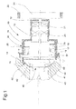
- Fig. 1 shows an automotive coolant radial pump, which is divided along its axis of symmetry: the upper half of Fig. 1 shows the radial pump 10 in the cold state in the closed position and the lower half shows the radial pump 10 in the warm state.
- the radial pump 10 is inserted into an engine block 60, and has a pump housing 30 with a radial impeller 11 which projects completely into the engine block 60.
- a vane wheel 12 carrying the impeller 11 passes through a sealing element 13 which may be formed as a lip seal.
- the shaft 12 is rotatably mounted beyond the sealing element 13 by two shaft bearings 20,21 and driven by a pulley 24 on which a drive belt 22 runs.
- the impeller 11 has a circular disk-shaped rear wall 41, an annular cover disk 42 and a plurality of vanes 43 therebetween.
- the radial impeller 11 has on its outer circumference on a circumferential radial impeller outlet 40, through which the coolant, which flows through a central opening 46 of the impeller 11 in the impeller 11, the rotating impeller 11, leaves in an annular channel 48.
- the radial pump 10 is formed clutch-free.
- a non-rotating and axially displaceable valve tube 14 is provided, which is inserted axially in its shooting position shown in the upper half of the drawing in the annular channel 48 and the impeller outlet 44 includes contact. In the one shown in the upper half Closing position is promoted virtually no coolant.
- the valve wheel 14 is formed as a hollow cylinder.
- the valve tube 14 is actuated by an actuator 16, which is in the present case designed as a wax element.
- a wax element may, for example, consist of a cylinder filled with wax, which has a relatively high coefficient of expansion, in which a piston slides which actuates the frame 52 via a piston rod 18.
- the actuator 16 may alternatively be formed as a bimetallic spring.
- the actuator 16 and the valve tube 14 are connected to each other via an axially displaceable frame 52.
- the frame 52 and the valve tube 14 are pushed axially into the open position shown below, in which the valve tube 14 no longer protrudes into the annular channel 48, and no longer the impeller outlet 44 closes.
- the frame 52 and the valve tube 14 is biased in the closed position, so that the valve tube 14 is pushed into the closed position when the coolant in the pump housing 30 has cooled back to ambient temperature.
- an electrical heating element 25 is arranged on the actuator 16.
- the heating element 25 can be switched on as needed, for example, as soon as the internal combustion engine is running. As a result, the heating of the actuator 16 is accelerated.
- the housing 30 carries directly the two shaft bearings 20,21 and the actuator 16, and leads the valve tube frame 52 axially.
Landscapes
- Engineering & Computer Science (AREA)
- Mechanical Engineering (AREA)
- General Engineering & Computer Science (AREA)
- Structures Of Non-Positive Displacement Pumps (AREA)
- Motor Or Generator Cooling System (AREA)
- Sorption Type Refrigeration Machines (AREA)
- Rotary Pumps (AREA)
- Temperature-Responsive Valves (AREA)
- Iron Core Of Rotating Electric Machines (AREA)
- Fluid-Driven Valves (AREA)
Description
- Die Erfindung betrifft eine mechanisch angetriebene Kühlmittel-Radialpumpe für ein mit einem Verbrennungsmotor angetriebenes Kraftfahrzeug, mit einem Radial-Flügelrad, das einen radialen Kühlmittel-Auslass aufweist.
- Im Stand der Technik sind Kühlmittel-Radialpumpen für Kfz-Verbrennungsmotoren beschrieben, die über eine Riemenscheibe von der Kurbelwelle des Verbrennungsmotors angetrieben werden und bei denen das Flügelrad durch eine Kupplung schaltbar von der Pumpenwelle angetrieben wird.
- Mit der mit solchen Kühlmittel-Radialpumpen realisierbaren Zweipunktregelung kann die Kühlleistung der Radialpumpe variiert werden. Diese Regelung ermöglicht es, dass eine unmittelbar nach dem Anlassen des Verbrennungsmotors einsetzende Zwangskühlung vermieden werden kann, wodurch die Warmlaufphase des Verbrennungsmotors mit den in dieser Phase auftretenden Nachteilen, wie beispielsweise erhöhten Reibungsverlusten, erhöhten Emissionswerten und einem erhöhten Kraftstoffverbrauch, deutlich verkürzt werden kann.
- Aus der
DE 100 57 098 C1 ist eine regelbare Kühlmittel-Pumpe bekannt, bei der stationär im Pumpengehäuse eine Magnetspule angeordnet ist, welche mit einer drehfest, jedoch federbelastet verschiebbar auf der Antriebswelle angeordneten, flügelradseitig mit einem Reibbelag versehenen Ankerscheibe derart in Wirkverbindung treten kann, dass bei abgeschaltetem Magnetfeld infolge der Federanpreßkraft das drehbar auf der Antriebswelle angeordnete Flügelrad von der Ankerscheibe mitgenommen wird. - Aus der
EP 1 657 446 A2 ist eine über eine Riemenscheibe angetriebene regelbare Kühlmittel-Radialpumpe für Verbrennungsmotoren bekannt, bei der im Pumpengehäuse ein Magnetgehäuse mit einer Magnetspule und ein mit einem Magnetanker versehener, durch eine Druckfeder belasteter Ventilschieber angeordnet ist, dessen Ventilrohr mit seinem Innendurchmesser den Außendurchmesser des Flügelrades bzw. des Flügelrad-Auslasses geringfügig überragt, und der axial so verschoben werden kann, dass in einer Öffnungsposition des Ventilrohres der Zufluss vom Flügelrad in den Auslass-Ringkanal frei gegeben und in der Schließposition des Ventilrohrs der Zufluss vom Flügelrad in den Ringkanal versperrt ist. - Hierdurch ist es möglich, die Kühlmittelmenge aktiv zu steuern, um einerseits eine schnellstmögliche Erwärmung des Motors zu gewährleisten und gleichzeitig nach dem Erwärmen des Motors die Motortemperatur im Dauerbetrieb so zu beeinflussen, dass im gesamten Arbeitsbereich des Motors sowohl die Schadstoffemission wie auch die Reibungsverluste und der Kraftstoffverbrauch deutlich reduziert werden können. Allerdings ist diese Lösung sehr aufwendig und teuer in der Herstellung
- Aus
US 4,828,455 A ist eine mechanische Kfz-Kühlmittel-Radialpumpe bekannt, die alle Merkmale des Oberbegriffs des Anspruchs 1 offenbart, und bei der ein verschiebbares Ventilrohr den radialen Flügelrad-Auslass zu dem Ringkanal durch axiales Verschieben Verschließen bzw. Freigeben kann. Das Ventilrohr wird durch einen rotierenden Wachselement-Aktuator aktuiert. - Eine ähnliche Kfz-Kühlmittel-Radialpumpe ist aus
US 5,169,286 A bekannt, bei der das Ventilrohr jedoch durch eine Feder mit einem sogenannten Formgedächtnis aktuiert wird. - Aus
DE 10344309 A1 ist eine Kfz-Kühlmittel-Radialpumpe bekannt, bei der ein blockförmiger Schieber in den gesamten Hohlraum des Pumpenrades axial geschoben werden kann. Der Schieber wird durch ein pumpenaußenseitig vorgesehenen Aktuator über einen Hebel axial aktuiert. - Aus
DE 2005004315 A1 ist eine Kfz-Kühlmittel-Radialpumpe bekannt, die zum Verschließen bzw. Freigeben des Flügelradauslasses ein axial verschiebbares Ventilrohr aufweist. Das Ventilrohr wird durch einen elektromagnetischen Aktuator axial betätigt. - Aufgabe der Erfindung ist es demgegenüber, eine steuerbare mechanische Kühlmittel-Radialpumpe zu schaffen, die einfach aufgebaut und kostengünstig herstellbar ist.
- Diese Aufgabe wird erfindungsgemäß gelöst durch eine mechanische Kfz-Kühlmittel-Radialpumpe mit den Merkmalen des Patentanspruches 1.
- Die erfindungsgemäße Radialpumpe weist ein Pumpengehäuse, ein Radial-Flügelrad mit einem radialen Kühlmittel-Auslass, einen in den radialen Flügelrad-Auslass umgebenden Auslass-Ringkanal, ein axial verschiebbares Ventilrohr, und einen mechanischen temperaturgesteuerten Ventilrohr-Aktuator auf. Das verschiebbare Ventilrohr ist zum Verschließen des Flügelrad-Auslasses in den Ringkanal in eine Schließposition einschiebbar, so dass es den Flügelrad-Auslass umgibt und verschließt. Der mechanische temperaturgesteuerte Ventilrohr-Aktuator ist in dem von dem Pumpengehäuse umschlossenen Kühlmittelraum angeordnet, wobei der Aktuator das Ventilrohr bei Erwärmung des Aktuators in die Ventilrohr-Öffnungsposition schiebt.
- Die Steuerung beziehungsweise Regelung der mechanisch angetriebenen Radialpumpe erfolgt also rein mechanisch durch einen temperaturgesteuerten Aktuator, der unmittelbar von dem Kühlmittel in dem Kühlmittelraum umgeben ist. Die Steuerung der Radialpumpe erfolgt also auf Grundlage der KühlmittelTemperatur innerhalb der Radialpumpe. Außerhalb der Radialpumpe sind keinerlei Bauelemente vorgesehen, die für die temperaturgeführte Steuerung der Radialpumpe erforderlich sind. Eine elektrische Versorgung der Radialpumpe entfällt.
- Das Kühlmittel in dem Pumpengehäuse der Radialpumpe nimmt aufgrund der unvermeidlichen freien Konvektion des Kühlmittels mit einer gewissen Verzögerung stets die Temperatur des Kühlmittels außerhalb der Radialpumpe an. Die hierdurch auftretende Verzögerung ist jedoch nicht schädlich, da die eigentliche Temperaturregelung des Kühlmittels durch ein separates Thermostat erfolgt. Die Steuerung der Radialpumpe dient ausschließlich dazu, während des Kaltlaufs des Verbrennungsmotors das Kühlmittel nicht umzuwälzen, um die Erwärmung des Verbrennungsmotors zu beschleunigen.
- Die erfindungsgemäße Radialpumpe ermöglicht es, den Kühlmitteldurchgang durch die Pumpe während des Kaltlaufs des Verbrennungsmotors zu verschließen, um die Kühlung des Verbrennungsmotors in dieser Phase zu minimieren. Selbst bei frei drehendem Flügelrad ist die Durchflußrate an Kühlmittel zum Verbrennungsmotor annähernd Null, da der Kühlmitteldurchtritt durch den Flügelrad-Auslass durch das Ventilrohr in Schließposition verhindert wird. Auf diese Weise wird ein schnelleres Warmlaufen des Verbrennungsmotors erreicht. Bei steigenden Temperaturen wird der Flügelrad-Auslass geöffnet, und die Kühlmittel-Durchtrittsrate erhöht sich bis zu einem Maximum. Es wird somit eine temperaturgesteuerte Kühlmittel-Radialpumpe geschaffen, die einfach aufgebaut und daher kostengünstig herstellbar ist.
- Der Aktuator ist als Wachselement ausgebildet. Ein Wachselement- Aktuator ist sehr preiswert, einfach aufgebaut, robust und zuverlässig.
- Dem Aktuator ist ein elektrisches Heizelement zugeordnet, durch das der Aktuator beheizbar ist. Solange das Ventilrohr in seiner Schießposition steht, erwärmt sich das Kühlmittel in dem Pumpengehäuse im Wesentlichen durch passive Konvektion. Die tatsächliche Temperatur des Verbrennungsmotors beziehungsweise des Kühlmittels in dem Verbrennungsmotor erreicht die Radialpumpe daher nur mit Verzögerung. Diese Verzögerung kann verringert werden, indem das Heizelement den Aktuator aktiv erwärmt, sobald der Verbrennungsmotor läuft. Hierdurch wird die Verzögerung so verringert, dass das Ventilrohr tatsächlich öffnet, sobald die Umwälzung des Kühlmittels im Kühlkreislauf durch die Radialpumpe gewünscht beziehungsweise erforderlich ist.
- Ein Wachselement- Aktuator kann im Wesentlichen Druckkräfte bei Erwärmung generieren, wohingegen die Zugkräfte bei Abkühlung relativ gering sind. Daher ist bevorzugt eine Vorspannfeder vorgesehen, die das Ventilrohr in die Schließposition vorgespannt.
- Nachfolgend wird ein Ausführungsbeispiel der Erfindung anhand der Zeichnung näher erläutert.
- Es zeigt
- Fig. 1
- eine mechanische Kfz-Kühlmittel-Radialpumpe in Schließposition in der oberen Hälfte und in Öffnungsposition in der unteren Hälfte.
-
Fig. 1 zeigt einen Kfz-Kühlmittel-Radialpumpe, die entlang ihrer Symmetrieachse geteilt ist: Die obere Hälfte vonFig. 1 zeigt die Radialpumpe 10 im kalten Zustand in Schließposition und die untere Hälfte zeigt die Radialpumpe 10 im warmen Zustand. - Wie aus
Fig. 1 ersichtlich, ist die Radialpumpe 10 in einen Motorblock 60 eingesetzt, und weist ein Pumpengehäuse 30 mit einem Radial-Flügelrad 11 auf, das vollständig in den Motorblock 60 hineinragt. Eine das Flügelrad 11 tragende Flügelrad-Welle 12 durchtritt ein Dichtelement 13, das als Lippendichtung ausgebildet sein kann. Die Welle 12 ist jenseits des Dichtelements 13 durch zwei Wellenlager 20,21 drehbar gelagert und durch eine Riemenscheibe 24, auf der ein Antriebsriemen 22 läuft, angetrieben. - Das Flügelrad 11 weist eine kreisscheibenförmige Rückwand 41, eine kreisringförmige Deckscheibe 42 sowie eine Vielzahl von Flügeln 43 dazwischen auf. Das Radial-Flügelrad 11 weist an seinem Außenumfang einen umlaufenden radialen Flügelrad-Auslass 40 auf, durch den das Kühlmittel, das durch eine Zentralöffnung 46 des Flügelrades 11 in das Flügelrad 11 einströmt, das rotierende Flügelrad 11, in einen Ringkanal 48 verlässt.
- Die Radialpumpe 10 ist kupplungsfrei ausgebildet. Zur Öffnung und Schließung der Radialpumpe 10 ist ein nicht-rotierendes und axial verschiebbares Ventilrohr 14 vorgesehen, das in seiner in der oberen Zeichnungshälfte dargestellten Schießposition in den Ringkanal 48 axial eingeschoben ist und den Flügelrad-Auslass 44 kontaktfrei umfasst. In der in der oberen Hälfte dargestellten Schließposition wird praktisch kein Kühlmittel gefördert. Das Ventilrad 14 ist hohlzylindrisch ausgebildet.
- Das Ventilrohr 14 wird durch einen Aktuator 16 betätigt, der vorliegend als Wachselement ausgebildet ist. Ein Wachselement kann beispielsweise aus einem mit Wachs, das einen relativ hohen Ausdehnungskoeffizienten hat, gefüllten Zylinder bestehen, in dem ein Kolben gleitet, der über eine Kolbenstange 18 das Gestell 52 betätigt.
- Der Aktuator 16 kann alternativ aber auch als Bimetallfeder ausgebildet sein. Der Aktuator 16 und das Ventilrohr 14 sind über ein axial verschiebbares Gestell 52 miteinander verbunden. Bei Erwärmung des Kühlmittels innerhalb des Gehäuses 30 wird auch der Aktuator 16 entsprechend erwärmt. Durch den sich erwärmenden Aktuator 16 werden das Gestell 52 und das Ventilrohr 14 axial in die unten dargestellte Öffnungsposition geschoben, in der das Ventilrohr 14 nicht mehr in den Ringkanal 48 hineinragt, und nicht mehr den Flügelrad-Auslass 44 verschließt.
- Durch eine Vorspannfeder 15 ist das Gestell 52 beziehungsweise das Ventilrohr 14 in die Schließposition vorgespannt, so dass das Ventilrohr 14 in die Schließposition geschoben wird, wenn das Kühlmittel in dem Pumpengehäuse 30 sich wieder auf Umgebungstemperatur abgekühlt hat.
- Zur optionalen Beschleunigung des temperaturabhängigen Öffnens des Ventilrohrs 14 ein elektrisches Heizelement 25 an dem Aktuator 16 angeordnet. Das Heizelement 25 kann bei Bedarf, beispielsweise sobald der Verbrennungsmotor läuft, eingeschaltet werden. Hierdurch wird die Erwärmung des Aktuators 16 beschleunigt.
- Das Gehäuse 30 trägt unmittelbar die beiden Wellenlager 20,21 und den Aktuator 16, und führt das Ventilrohr-Gestell 52 axial.
Claims (2)
- Mechanische Kfz-Kühlmittel-Radialpumpe (10) mit
einem Pumpengehäuse (30),
einem Flügelrad (11) mit einem radialen Kühlmittel-Auslass (44),
einem den radialen Flügelrad-Auslass (44) umgebenden Auslass-Ringkanal (48), und
einem axial verschiebbaren Ventilrohr (14), das zum Verschließen des Flügelrad- Auslasses (44) in den Ringkanal (48) in eine Schließposition einschiebbar ist, so dass es den Flügelrad-Auslass (44) umgibt und verschließt,
wobei ein mechanischer temperaturgesteuerter Ventilrohr- Aktuator (16) in dem von dem Pumpengehäuse (30) umschlossenen Kühlmittelraum angeordnet ist, wobei der Aktuator (16), das Ventilrohr (14) bei Erwärmung des Aktuators (16) in seine Öffnungsposition schiebt, und
wobei der Aktuator (16) als Wachselement ausgebildet ist,
dadurch gekennzeichnet, dass
das Ventilrohr (14) nicht-rotierend ist, und
dass dem Aktuator (16) ein elektrisches Heizelement (24) zugeordnet ist, durch das der Aktuator (16) beheizbar ist. - Mechanische Kfz-Kühlmittel-Radialpumpe (10) nach Anspruch 1, wobei das Ventilrohr (14) durch eine Vorspannfeder (15) in Richtung Schließposition oder Öffnungsposition vorgespannt ist.
Priority Applications (5)
| Application Number | Priority Date | Filing Date | Title |
|---|---|---|---|
| AT08171765T ATE556225T1 (de) | 2008-12-16 | 2008-12-16 | Mechanische kfz-kühlmittel-radialpumpe |
| DK08171765.4T DK2199619T3 (da) | 2008-12-16 | 2008-12-16 | Mekanisk radialpumpe til kølemiddel til motorkøretøjer |
| ES08171765T ES2390477T3 (es) | 2008-12-16 | 2008-12-16 | Bomba de refrigerante radial mecánica para automóvil |
| PL08171765T PL2199619T3 (pl) | 2008-12-16 | 2008-12-16 | Mechaniczna pompa promieniowa dla cieczy chłodzącej pojazdów |
| EP08171765A EP2199619B1 (de) | 2008-12-16 | 2008-12-16 | Mechanische Kfz-Kühlmittel-Radialpumpe |
Applications Claiming Priority (1)
| Application Number | Priority Date | Filing Date | Title |
|---|---|---|---|
| EP08171765A EP2199619B1 (de) | 2008-12-16 | 2008-12-16 | Mechanische Kfz-Kühlmittel-Radialpumpe |
Publications (2)
| Publication Number | Publication Date |
|---|---|
| EP2199619A1 EP2199619A1 (de) | 2010-06-23 |
| EP2199619B1 true EP2199619B1 (de) | 2012-05-02 |
Family
ID=40548960
Family Applications (1)
| Application Number | Title | Priority Date | Filing Date |
|---|---|---|---|
| EP08171765A Not-in-force EP2199619B1 (de) | 2008-12-16 | 2008-12-16 | Mechanische Kfz-Kühlmittel-Radialpumpe |
Country Status (5)
| Country | Link |
|---|---|
| EP (1) | EP2199619B1 (de) |
| AT (1) | ATE556225T1 (de) |
| DK (1) | DK2199619T3 (de) |
| ES (1) | ES2390477T3 (de) |
| PL (1) | PL2199619T3 (de) |
Families Citing this family (2)
| Publication number | Priority date | Publication date | Assignee | Title |
|---|---|---|---|---|
| DE102011087141A1 (de) * | 2011-11-25 | 2013-05-29 | Behr Thermot-Tronik Gmbh | Pumpe |
| DE102015000805B3 (de) * | 2015-01-22 | 2016-01-21 | Nidec Gpm Gmbh | Regelbare Kühlmittelpumpe |
Family Cites Families (5)
| Publication number | Priority date | Publication date | Assignee | Title |
|---|---|---|---|---|
| US4828455A (en) | 1982-12-21 | 1989-05-09 | Aisin Seiki Kabushiki Kaisha | Temperature responsive blade shroud-disk for thermostatic water pump |
| US5169286A (en) | 1989-03-09 | 1992-12-08 | Yutaka Yamada | Variable capacity centrifugal water pump with movable pressure chamber formed by impeller |
| DE10344309A1 (de) | 2003-09-23 | 2005-04-21 | Ticu Aci | Förderpumpe |
| DE102004054637B4 (de) | 2004-11-12 | 2007-04-26 | Geräte- und Pumpenbau GmbH Dr. Eugen Schmidt | Regelbare Kühlmittelpumpe |
| DE102005004315B4 (de) | 2005-01-31 | 2007-04-26 | Geräte- und Pumpenbau GmbH Dr. Eugen Schmidt | Regelbare Kühlmittelpumpe |
-
2008
- 2008-12-16 AT AT08171765T patent/ATE556225T1/de active
- 2008-12-16 PL PL08171765T patent/PL2199619T3/pl unknown
- 2008-12-16 EP EP08171765A patent/EP2199619B1/de not_active Not-in-force
- 2008-12-16 ES ES08171765T patent/ES2390477T3/es active Active
- 2008-12-16 DK DK08171765.4T patent/DK2199619T3/da active
Also Published As
| Publication number | Publication date |
|---|---|
| PL2199619T3 (pl) | 2012-11-30 |
| ES2390477T3 (es) | 2012-11-13 |
| ATE556225T1 (de) | 2012-05-15 |
| DK2199619T3 (da) | 2012-08-20 |
| EP2199619A1 (de) | 2010-06-23 |
Similar Documents
| Publication | Publication Date | Title |
|---|---|---|
| DE2804557C3 (de) | Flüssigkeitsreibungskupplung, insbesondere für ein Kühlgebläse einer Brennkraftmaschine | |
| DE102005004315B4 (de) | Regelbare Kühlmittelpumpe | |
| DE102004054637B4 (de) | Regelbare Kühlmittelpumpe | |
| EP0361053B1 (de) | Heizvorrichtung für den Fahrgastraum eines eine flüssigkeitsgekühlte Brennkraftmaschine aufweisenden Kraftfahrzeuges | |
| JP3186787U (ja) | 燃料用噴射ノズル | |
| DE102015000805B3 (de) | Regelbare Kühlmittelpumpe | |
| CN103946504A (zh) | 具有电动液压导流板调整装置的能调节的冷却剂泵 | |
| DE102008022500A1 (de) | Lüfterkupplung | |
| DE4420841A1 (de) | Heizvorrichtung für Kraftfahrzeuge | |
| DE112010005507T5 (de) | Motorkühlvorrichtung | |
| DE102008039700A1 (de) | Kühlmittelpumpe | |
| DE102014114590A1 (de) | Hydrauliksteuervorrichtung für Hydraulikdrehmomentwandler | |
| EP2199619A1 (de) | Mechanische Kfz-Kühlmittel-Radialpumpe | |
| US9587683B2 (en) | Viscous clutch drive with electromagnetic activation and wiper on clutch disk | |
| DE3329002C2 (de) | Kühlmittelpumpe an einer Brennkraftmaschine für insbesondere Fahrzeuge | |
| WO2018170291A1 (en) | Actuator for solenoid operated valve | |
| DE8908357U1 (de) | Flüssigkeitsreibungskupplung | |
| DE10131792C1 (de) | Kühlmittelpumpe | |
| DE102016116636A1 (de) | Kühlmittelpumpe für den Kfz-Bereich sowie ein Kühlmittelkreislauf für eine Verbrennungskraftmaschine | |
| DE10235721A1 (de) | Regelbare Kühlmittelpumpe | |
| JP6584665B2 (ja) | 内燃機関用の機械的に調整可能な冷却媒体ポンプを調整する方法 | |
| CN105307814B (zh) | 配备有轴和相关安装元件的复合壳体的组装方法 | |
| US20170059054A1 (en) | Valve configured regulating the flow of fluid between a device, a heater, and a cooler | |
| DE102008054750A1 (de) | Kühlmittelregelventil | |
| DE102018217479A1 (de) | Wasserpumpe für ein kraftfahrzeug |
Legal Events
| Date | Code | Title | Description |
|---|---|---|---|
| PUAI | Public reference made under article 153(3) epc to a published international application that has entered the european phase |
Free format text: ORIGINAL CODE: 0009012 |
|
| AK | Designated contracting states |
Kind code of ref document: A1 Designated state(s): AT BE BG CH CY CZ DE DK EE ES FI FR GB GR HR HU IE IS IT LI LT LU LV MC MT NL NO PL PT RO SE SI SK TR |
|
| AX | Request for extension of the european patent |
Extension state: AL BA MK RS |
|
| 17P | Request for examination filed |
Effective date: 20101001 |
|
| 17Q | First examination report despatched |
Effective date: 20101111 |
|
| AKX | Designation fees paid |
Designated state(s): AT BE BG CH CY CZ DE DK EE ES FI FR GB GR HR HU IE IS IT LI LT LU LV MC MT NL NO PL PT RO SE SI SK TR |
|
| GRAP | Despatch of communication of intention to grant a patent |
Free format text: ORIGINAL CODE: EPIDOSNIGR1 |
|
| RIC1 | Information provided on ipc code assigned before grant |
Ipc: F04D 15/00 20060101AFI20120113BHEP |
|
| GRAS | Grant fee paid |
Free format text: ORIGINAL CODE: EPIDOSNIGR3 |
|
| GRAA | (expected) grant |
Free format text: ORIGINAL CODE: 0009210 |
|
| AK | Designated contracting states |
Kind code of ref document: B1 Designated state(s): AT BE BG CH CY CZ DE DK EE ES FI FR GB GR HR HU IE IS IT LI LT LU LV MC MT NL NO PL PT RO SE SI SK TR |
|
| REG | Reference to a national code |
Ref country code: GB Ref legal event code: FG4D Free format text: NOT ENGLISH |
|
| REG | Reference to a national code |
Ref country code: AT Ref legal event code: REF Ref document number: 556225 Country of ref document: AT Kind code of ref document: T Effective date: 20120515 Ref country code: CH Ref legal event code: EP |
|
| REG | Reference to a national code |
Ref country code: IE Ref legal event code: FG4D Free format text: LANGUAGE OF EP DOCUMENT: GERMAN |
|
| REG | Reference to a national code |
Ref country code: DE Ref legal event code: R096 Ref document number: 502008007117 Country of ref document: DE Effective date: 20120628 |
|
| REG | Reference to a national code |
Ref country code: NL Ref legal event code: T3 |
|
| REG | Reference to a national code |
Ref country code: SE Ref legal event code: TRGR |
|
| REG | Reference to a national code |
Ref country code: DK Ref legal event code: T3 |
|
| REG | Reference to a national code |
Ref country code: NO Ref legal event code: T2 Effective date: 20120502 |
|
| REG | Reference to a national code |
Ref country code: LT Ref legal event code: MG4D Effective date: 20120502 |
|
| PG25 | Lapsed in a contracting state [announced via postgrant information from national office to epo] |
Ref country code: LT Free format text: LAPSE BECAUSE OF FAILURE TO SUBMIT A TRANSLATION OF THE DESCRIPTION OR TO PAY THE FEE WITHIN THE PRESCRIBED TIME-LIMIT Effective date: 20120502 Ref country code: FI Free format text: LAPSE BECAUSE OF FAILURE TO SUBMIT A TRANSLATION OF THE DESCRIPTION OR TO PAY THE FEE WITHIN THE PRESCRIBED TIME-LIMIT Effective date: 20120502 Ref country code: CY Free format text: LAPSE BECAUSE OF FAILURE TO SUBMIT A TRANSLATION OF THE DESCRIPTION OR TO PAY THE FEE WITHIN THE PRESCRIBED TIME-LIMIT Effective date: 20120502 Ref country code: IS Free format text: LAPSE BECAUSE OF FAILURE TO SUBMIT A TRANSLATION OF THE DESCRIPTION OR TO PAY THE FEE WITHIN THE PRESCRIBED TIME-LIMIT Effective date: 20120902 |
|
| REG | Reference to a national code |
Ref country code: ES Ref legal event code: FG2A Ref document number: 2390477 Country of ref document: ES Kind code of ref document: T3 Effective date: 20121113 |
|
| PG25 | Lapsed in a contracting state [announced via postgrant information from national office to epo] |
Ref country code: LV Free format text: LAPSE BECAUSE OF FAILURE TO SUBMIT A TRANSLATION OF THE DESCRIPTION OR TO PAY THE FEE WITHIN THE PRESCRIBED TIME-LIMIT Effective date: 20120502 Ref country code: GR Free format text: LAPSE BECAUSE OF FAILURE TO SUBMIT A TRANSLATION OF THE DESCRIPTION OR TO PAY THE FEE WITHIN THE PRESCRIBED TIME-LIMIT Effective date: 20120803 Ref country code: SI Free format text: LAPSE BECAUSE OF FAILURE TO SUBMIT A TRANSLATION OF THE DESCRIPTION OR TO PAY THE FEE WITHIN THE PRESCRIBED TIME-LIMIT Effective date: 20120502 Ref country code: PT Free format text: LAPSE BECAUSE OF FAILURE TO SUBMIT A TRANSLATION OF THE DESCRIPTION OR TO PAY THE FEE WITHIN THE PRESCRIBED TIME-LIMIT Effective date: 20120903 Ref country code: HR Free format text: LAPSE BECAUSE OF FAILURE TO SUBMIT A TRANSLATION OF THE DESCRIPTION OR TO PAY THE FEE WITHIN THE PRESCRIBED TIME-LIMIT Effective date: 20120502 |
|
| REG | Reference to a national code |
Ref country code: PL Ref legal event code: T3 |
|
| PG25 | Lapsed in a contracting state [announced via postgrant information from national office to epo] |
Ref country code: SK Free format text: LAPSE BECAUSE OF FAILURE TO SUBMIT A TRANSLATION OF THE DESCRIPTION OR TO PAY THE FEE WITHIN THE PRESCRIBED TIME-LIMIT Effective date: 20120502 Ref country code: CZ Free format text: LAPSE BECAUSE OF FAILURE TO SUBMIT A TRANSLATION OF THE DESCRIPTION OR TO PAY THE FEE WITHIN THE PRESCRIBED TIME-LIMIT Effective date: 20120502 Ref country code: EE Free format text: LAPSE BECAUSE OF FAILURE TO SUBMIT A TRANSLATION OF THE DESCRIPTION OR TO PAY THE FEE WITHIN THE PRESCRIBED TIME-LIMIT Effective date: 20120502 Ref country code: RO Free format text: LAPSE BECAUSE OF FAILURE TO SUBMIT A TRANSLATION OF THE DESCRIPTION OR TO PAY THE FEE WITHIN THE PRESCRIBED TIME-LIMIT Effective date: 20120502 |
|
| PLBE | No opposition filed within time limit |
Free format text: ORIGINAL CODE: 0009261 |
|
| STAA | Information on the status of an ep patent application or granted ep patent |
Free format text: STATUS: NO OPPOSITION FILED WITHIN TIME LIMIT |
|
| 26N | No opposition filed |
Effective date: 20130205 |
|
| REG | Reference to a national code |
Ref country code: DE Ref legal event code: R097 Ref document number: 502008007117 Country of ref document: DE Effective date: 20130205 |
|
| PG25 | Lapsed in a contracting state [announced via postgrant information from national office to epo] |
Ref country code: BG Free format text: LAPSE BECAUSE OF FAILURE TO SUBMIT A TRANSLATION OF THE DESCRIPTION OR TO PAY THE FEE WITHIN THE PRESCRIBED TIME-LIMIT Effective date: 20120802 Ref country code: MC Free format text: LAPSE BECAUSE OF NON-PAYMENT OF DUE FEES Effective date: 20121231 |
|
| REG | Reference to a national code |
Ref country code: CH Ref legal event code: PL |
|
| GBPC | Gb: european patent ceased through non-payment of renewal fee |
Effective date: 20121216 |
|
| REG | Reference to a national code |
Ref country code: IE Ref legal event code: MM4A |
|
| REG | Reference to a national code |
Ref country code: HU Ref legal event code: AG4A Ref document number: E016741 Country of ref document: HU |
|
| PG25 | Lapsed in a contracting state [announced via postgrant information from national office to epo] |
Ref country code: CH Free format text: LAPSE BECAUSE OF NON-PAYMENT OF DUE FEES Effective date: 20121231 Ref country code: LI Free format text: LAPSE BECAUSE OF NON-PAYMENT OF DUE FEES Effective date: 20121231 Ref country code: IE Free format text: LAPSE BECAUSE OF NON-PAYMENT OF DUE FEES Effective date: 20121216 |
|
| PG25 | Lapsed in a contracting state [announced via postgrant information from national office to epo] |
Ref country code: MT Free format text: LAPSE BECAUSE OF FAILURE TO SUBMIT A TRANSLATION OF THE DESCRIPTION OR TO PAY THE FEE WITHIN THE PRESCRIBED TIME-LIMIT Effective date: 20120502 Ref country code: GB Free format text: LAPSE BECAUSE OF NON-PAYMENT OF DUE FEES Effective date: 20121216 |
|
| PGFP | Annual fee paid to national office [announced via postgrant information from national office to epo] |
Ref country code: SE Payment date: 20131217 Year of fee payment: 6 Ref country code: DK Payment date: 20131219 Year of fee payment: 6 Ref country code: NO Payment date: 20131217 Year of fee payment: 6 |
|
| PGFP | Annual fee paid to national office [announced via postgrant information from national office to epo] |
Ref country code: NL Payment date: 20131216 Year of fee payment: 6 Ref country code: HU Payment date: 20131203 Year of fee payment: 6 Ref country code: ES Payment date: 20131216 Year of fee payment: 6 Ref country code: PL Payment date: 20131204 Year of fee payment: 6 |
|
| PGFP | Annual fee paid to national office [announced via postgrant information from national office to epo] |
Ref country code: BE Payment date: 20131216 Year of fee payment: 6 |
|
| PG25 | Lapsed in a contracting state [announced via postgrant information from national office to epo] |
Ref country code: TR Free format text: LAPSE BECAUSE OF FAILURE TO SUBMIT A TRANSLATION OF THE DESCRIPTION OR TO PAY THE FEE WITHIN THE PRESCRIBED TIME-LIMIT Effective date: 20120502 |
|
| PG25 | Lapsed in a contracting state [announced via postgrant information from national office to epo] |
Ref country code: LU Free format text: LAPSE BECAUSE OF NON-PAYMENT OF DUE FEES Effective date: 20121216 |
|
| REG | Reference to a national code |
Ref country code: AT Ref legal event code: MM01 Ref document number: 556225 Country of ref document: AT Kind code of ref document: T Effective date: 20131216 |
|
| PG25 | Lapsed in a contracting state [announced via postgrant information from national office to epo] |
Ref country code: AT Free format text: LAPSE BECAUSE OF NON-PAYMENT OF DUE FEES Effective date: 20131216 |
|
| PG25 | Lapsed in a contracting state [announced via postgrant information from national office to epo] |
Ref country code: BE Free format text: LAPSE BECAUSE OF NON-PAYMENT OF DUE FEES Effective date: 20141231 |
|
| REG | Reference to a national code |
Ref country code: DK Ref legal event code: EBP Effective date: 20141231 |
|
| REG | Reference to a national code |
Ref country code: NL Ref legal event code: V1 Effective date: 20150701 |
|
| REG | Reference to a national code |
Ref country code: NL Ref legal event code: V1 Effective date: 20150701 |
|
| PG25 | Lapsed in a contracting state [announced via postgrant information from national office to epo] |
Ref country code: SE Free format text: LAPSE BECAUSE OF NON-PAYMENT OF DUE FEES Effective date: 20141217 |
|
| REG | Reference to a national code |
Ref country code: SE Ref legal event code: EUG |
|
| PG25 | Lapsed in a contracting state [announced via postgrant information from national office to epo] |
Ref country code: NL Free format text: LAPSE BECAUSE OF NON-PAYMENT OF DUE FEES Effective date: 20150701 |
|
| PG25 | Lapsed in a contracting state [announced via postgrant information from national office to epo] |
Ref country code: NO Free format text: LAPSE BECAUSE OF NON-PAYMENT OF DUE FEES Effective date: 20141231 |
|
| PG25 | Lapsed in a contracting state [announced via postgrant information from national office to epo] |
Ref country code: HU Free format text: LAPSE BECAUSE OF NON-PAYMENT OF DUE FEES Effective date: 20141217 |
|
| REG | Reference to a national code |
Ref country code: FR Ref legal event code: PLFP Year of fee payment: 8 |
|
| REG | Reference to a national code |
Ref country code: ES Ref legal event code: FD2A Effective date: 20160126 |
|
| PG25 | Lapsed in a contracting state [announced via postgrant information from national office to epo] |
Ref country code: DK Free format text: LAPSE BECAUSE OF NON-PAYMENT OF DUE FEES Effective date: 20141231 |
|
| PG25 | Lapsed in a contracting state [announced via postgrant information from national office to epo] |
Ref country code: ES Free format text: LAPSE BECAUSE OF NON-PAYMENT OF DUE FEES Effective date: 20141217 |
|
| PG25 | Lapsed in a contracting state [announced via postgrant information from national office to epo] |
Ref country code: PL Free format text: LAPSE BECAUSE OF NON-PAYMENT OF DUE FEES Effective date: 20141216 |
|
| REG | Reference to a national code |
Ref country code: FR Ref legal event code: PLFP Year of fee payment: 9 |
|
| REG | Reference to a national code |
Ref country code: FR Ref legal event code: PLFP Year of fee payment: 10 |
|
| PGFP | Annual fee paid to national office [announced via postgrant information from national office to epo] |
Ref country code: FR Payment date: 20181218 Year of fee payment: 11 Ref country code: IT Payment date: 20181218 Year of fee payment: 11 |
|
| PGFP | Annual fee paid to national office [announced via postgrant information from national office to epo] |
Ref country code: DE Payment date: 20181220 Year of fee payment: 11 |
|
| REG | Reference to a national code |
Ref country code: DE Ref legal event code: R082 Ref document number: 502008007117 Country of ref document: DE Representative=s name: TERPATENT PATENTANWAELTE TER SMITTEN EBERLEIN-, DE |
|
| REG | Reference to a national code |
Ref country code: DE Ref legal event code: R119 Ref document number: 502008007117 Country of ref document: DE |
|
| PG25 | Lapsed in a contracting state [announced via postgrant information from national office to epo] |
Ref country code: FR Free format text: LAPSE BECAUSE OF NON-PAYMENT OF DUE FEES Effective date: 20191231 Ref country code: IT Free format text: LAPSE BECAUSE OF NON-PAYMENT OF DUE FEES Effective date: 20191216 Ref country code: DE Free format text: LAPSE BECAUSE OF NON-PAYMENT OF DUE FEES Effective date: 20200701 |