EP2199534B1 - Subsea electronic module - Google Patents
Subsea electronic module Download PDFInfo
- Publication number
- EP2199534B1 EP2199534B1 EP09176532.1A EP09176532A EP2199534B1 EP 2199534 B1 EP2199534 B1 EP 2199534B1 EP 09176532 A EP09176532 A EP 09176532A EP 2199534 B1 EP2199534 B1 EP 2199534B1
- Authority
- EP
- European Patent Office
- Prior art keywords
- ethernet
- local area
- interfaces
- networks
- bay
- Prior art date
- Legal status (The legal status is an assumption and is not a legal conclusion. Google has not performed a legal analysis and makes no representation as to the accuracy of the status listed.)
- Active
Links
- 238000004891 communication Methods 0.000 claims description 14
- 230000008878 coupling Effects 0.000 claims description 9
- 238000010168 coupling process Methods 0.000 claims description 9
- 238000005859 coupling reaction Methods 0.000 claims description 9
- 238000000605 extraction Methods 0.000 claims description 9
- 239000012530 fluid Substances 0.000 claims description 8
- 238000000034 method Methods 0.000 claims description 4
- 230000003287 optical effect Effects 0.000 description 7
- RYGMFSIKBFXOCR-UHFFFAOYSA-N Copper Chemical compound [Cu] RYGMFSIKBFXOCR-UHFFFAOYSA-N 0.000 description 4
- 229910052802 copper Inorganic materials 0.000 description 4
- 239000010949 copper Substances 0.000 description 4
- 125000003821 2-(trimethylsilyl)ethoxymethyl group Chemical group [H]C([H])([H])[Si](C([H])([H])[H])(C([H])([H])[H])C([H])([H])C(OC([H])([H])[*])([H])[H] 0.000 description 3
- 230000008901 benefit Effects 0.000 description 3
- 238000004626 scanning electron microscopy Methods 0.000 description 3
- 230000005540 biological transmission Effects 0.000 description 2
- 239000003990 capacitor Substances 0.000 description 2
- 238000007726 management method Methods 0.000 description 2
- 238000012544 monitoring process Methods 0.000 description 2
- 238000005204 segregation Methods 0.000 description 2
- 239000004215 Carbon black (E152) Substances 0.000 description 1
- 239000004020 conductor Substances 0.000 description 1
- 230000009977 dual effect Effects 0.000 description 1
- 238000005516 engineering process Methods 0.000 description 1
- 229930195733 hydrocarbon Natural products 0.000 description 1
- 150000002430 hydrocarbons Chemical class 0.000 description 1
- 238000009434 installation Methods 0.000 description 1
- 238000004519 manufacturing process Methods 0.000 description 1
- 238000012986 modification Methods 0.000 description 1
- 230000004048 modification Effects 0.000 description 1
- 238000012913 prioritisation Methods 0.000 description 1
- 230000009467 reduction Effects 0.000 description 1
- 230000000452 restraining effect Effects 0.000 description 1
- 229920006132 styrene block copolymer Polymers 0.000 description 1
- 239000013585 weight reducing agent Substances 0.000 description 1
Images

Classifications
-
- H—ELECTRICITY
- H04—ELECTRIC COMMUNICATION TECHNIQUE
- H04L—TRANSMISSION OF DIGITAL INFORMATION, e.g. TELEGRAPHIC COMMUNICATION
- H04L12/00—Data switching networks
- H04L12/28—Data switching networks characterised by path configuration, e.g. LAN [Local Area Networks] or WAN [Wide Area Networks]
- H04L12/40—Bus networks
-
- E—FIXED CONSTRUCTIONS
- E21—EARTH DRILLING; MINING
- E21B—EARTH DRILLING, e.g. DEEP DRILLING; OBTAINING OIL, GAS, WATER, SOLUBLE OR MELTABLE MATERIALS OR A SLURRY OF MINERALS FROM WELLS
- E21B33/00—Sealing or packing boreholes or wells
- E21B33/02—Surface sealing or packing
- E21B33/03—Well heads; Setting-up thereof
- E21B33/035—Well heads; Setting-up thereof specially adapted for underwater installations
- E21B33/0355—Control systems, e.g. hydraulic, pneumatic, electric, acoustic, for submerged well heads
-
- G—PHYSICS
- G06—COMPUTING; CALCULATING OR COUNTING
- G06F—ELECTRIC DIGITAL DATA PROCESSING
- G06F13/00—Interconnection of, or transfer of information or other signals between, memories, input/output devices or central processing units
- G06F13/38—Information transfer, e.g. on bus
- G06F13/40—Bus structure
- G06F13/4063—Device-to-bus coupling
- G06F13/4068—Electrical coupling
-
- G—PHYSICS
- G08—SIGNALLING
- G08C—TRANSMISSION SYSTEMS FOR MEASURED VALUES, CONTROL OR SIMILAR SIGNALS
- G08C17/00—Arrangements for transmitting signals characterised by the use of a wireless electrical link
- G08C17/06—Arrangements for transmitting signals characterised by the use of a wireless electrical link using capacity coupling
-
- H—ELECTRICITY
- H04—ELECTRIC COMMUNICATION TECHNIQUE
- H04L—TRANSMISSION OF DIGITAL INFORMATION, e.g. TELEGRAPHIC COMMUNICATION
- H04L12/00—Data switching networks
- H04L12/28—Data switching networks characterised by path configuration, e.g. LAN [Local Area Networks] or WAN [Wide Area Networks]
- H04L12/40—Bus networks
- H04L12/40169—Flexible bus arrangements
- H04L12/40176—Flexible bus arrangements involving redundancy
-
- H—ELECTRICITY
- H04—ELECTRIC COMMUNICATION TECHNIQUE
- H04L—TRANSMISSION OF DIGITAL INFORMATION, e.g. TELEGRAPHIC COMMUNICATION
- H04L25/00—Baseband systems
- H04L25/02—Details ; arrangements for supplying electrical power along data transmission lines
- H04L25/0264—Arrangements for coupling to transmission lines
- H04L25/0266—Arrangements for providing Galvanic isolation, e.g. by means of magnetic or capacitive coupling
-
- H—ELECTRICITY
- H04—ELECTRIC COMMUNICATION TECHNIQUE
- H04L—TRANSMISSION OF DIGITAL INFORMATION, e.g. TELEGRAPHIC COMMUNICATION
- H04L49/00—Packet switching elements
- H04L49/35—Switches specially adapted for specific applications
- H04L49/351—Switches specially adapted for specific applications for local area network [LAN], e.g. Ethernet switches
-
- H04B5/22—
-
- Y—GENERAL TAGGING OF NEW TECHNOLOGICAL DEVELOPMENTS; GENERAL TAGGING OF CROSS-SECTIONAL TECHNOLOGIES SPANNING OVER SEVERAL SECTIONS OF THE IPC; TECHNICAL SUBJECTS COVERED BY FORMER USPC CROSS-REFERENCE ART COLLECTIONS [XRACs] AND DIGESTS
- Y02—TECHNOLOGIES OR APPLICATIONS FOR MITIGATION OR ADAPTATION AGAINST CLIMATE CHANGE
- Y02D—CLIMATE CHANGE MITIGATION TECHNOLOGIES IN INFORMATION AND COMMUNICATION TECHNOLOGIES [ICT], I.E. INFORMATION AND COMMUNICATION TECHNOLOGIES AIMING AT THE REDUCTION OF THEIR OWN ENERGY USE
- Y02D10/00—Energy efficient computing, e.g. low power processors, power management or thermal management
Definitions
- This invention relates to a subsea electronic module for an underwater fluid extraction well, and a method of enabling Ethernet communication therefor.
- RAMSHAW J "Subsea Distributed Data Acquisition System”
- SUBSEA CONTROL AND DATA ACQUISITION FOR OIL AND GAS PRODUCTION SYSTMS PAPERS PRESENTED AT A CONFERENCE/ORGANIZED BY THE SOCIETY FOR UNDERWATER TECHNOLOGY AND HELD IN LONDON, UK, April 20-21,19,20 April 1994 (1994-04-20)
- pages 217-236 describes a subsea distributed data acquisition bus.
- SEM subsea electronic module
- SCM subsea control module
- DCVs hydraulic directional control valves
- Communication to and from the SEM is enabled via a modem if there are copper links, or an equivalent optical modem if optical links are employed.
- Modern SEMs utilise Ethernet communication between the electronic cards, which requires Ethernet switches to be mounted on the circuit boards.
- the electronic cards are arranged in sets as a 'bay', with a number of bays within the SEM. Further Ethernet switches are required to enable communication between the bays. Consequently, a large number of interfaces is required between all the Ethernet components, which components typically include switch blades. These interfaces are conventionally effected by transformers. However, transformers are expensive and consume significant space on the SEM electronic cards, which limits the functions available in an SEM whose dimensions are strictly limited by well operator customers.
- capacitive coupling is made viable through re-organisation of the cards within an SEM to ensure that transmission distances are small. This brings about major benefits in terms of cost and weight reduction, as well as allowing the functional repertoire of the SEM to be increased.
- the present invention therefore provides various advantages, including:
- an electronic module for use as a subsea electronic module for an underwater fluid extraction well, wherein a local area network enables communication within the module, the local area network including a plurality of interfaces with components of the network, and wherein the interfaces comprise capacitive coupling interfaces.
- an electronic module for use as a subsea electronic module for an underwater fluid extraction well, comprising a plurality of substantially planar electronics cards, wherein the cards are arranged in a stack such that the major faces of each card are substantially parallel to, and coaxial with, major faces of the other cards in the stack, and wherein the module further comprises a substantially planar switch card orientated relative to the stack such that its major faces are substantially parallel to the axis of the stack and orthogonal to the major faces of the cards within the stack and positioned such that the switch card is substantially equidistant from each card within the stack.
- a method of enabling Ethernet communication between Ethernet components within a subsea electronic module for an underwater fluid extraction well comprising the step of providing Ethernet interfacing between said components, said interfacing comprising a capacitance.
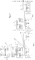
- Fig. 1 shows an example of a configuration of an Ethernet communication system within a multi-card, multi-bay SEM, in accordance with the present invention.
- interfaces for both an optical external interface 1 and a copper external interface 2 to the well control platform are shown. In practice, only one interface would be used, as described below.
- the selection of optical or copper interfaces 1, 2 is made to enable the SEM to be compatible with the form of interface required for a particular installation. In both cases, the interface connects to a first card (“CARD 1") within the SEM, which comprises an Ethernet switch 4 capacitively coupled to a single board computer (SBC) 5.
- CD single board computer
- optical interface 1 is connected to a small form-factor pluggable transceiver (SFP) 3, which acts as a media converter extending the topside LAN down to the SEM internal LAN(s) via an optical point to point Ethernet link, and thus provides an optical to electrical interface to the Ethernet switch 4.
- SFP small form-factor pluggable transceiver
- the SBC 5 supports the modem 11 and implements a bridge and interpreter / translator function for the modem communications.
- Ethernet switch 4 is connected to Ethernet switch 4, and so may handle communications to and from either external interface 1 or 2.
- Ethernet switch 4 is a managed switch capable of implementing key level three protocol router functions including Spanning Tree Protocol (STP) to ensure that no LAN loops are created between the SEM internal LANs (A and B - see below) and traffic management including bandwidth assignment and prioritization.
- STP Spanning Tree Protocol
- the configuration of the SEM shown has a number of bays each with a stack of six electronic cards.
- Fig. 1 only three cards (i.e. CARD 1, CARD 2 and CARD 6) are shown.
- CARD 1 and CARD 2 the configuration of the SEM shown has a number of bays each with a stack of six electronic cards.
- Fig. 1 only three cards (i.e. CARD 1, CARD 2 and CARD 6) are shown.
- only two bays of cards are shown for simplicity (i.e. Bay 1 and Bay 2), with extension of the system being provided by additional interfaces 7 and 8 for additional bays.
- the SEM shown supports two internal LANs A and B, providing redundancy. Traffic on LANs A and B are routed and managed via switch 4. The LANs A and B are segregated to assure single point failure tolerance.
- An ESB card of each bay includes a pair of Ethernet switch blades (ESBs) 6, denoted ESB A and ESB B, controlling LAN A and B traffic respectively.
- Each ESB 6 is an ummanaged eight-port Ethernet switch, with six ports assigned for connection to baymounted cards (i.e. CARD 1 - CARD 6) and two ports assigned for bay to bay connectivity. In Fig. 1 only four ports are shown connected.
- the Ethernet switch blades (ESBs) 6 of each CARD 1 are arranged in a dual configuration to provide system redundancy.
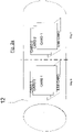
- Each ESB card is located above and orthogonal to the respective stack of six cards of the bay, as shown in Fig. 2 .
- Each card (i.e. CARD 1 - CARD 6) includes an SBC 10 which feeds electrical drivers to operate devices in the SEM, such as directional control valves (DCVs) and/or other electrical devices and also interface with monitoring sensors on the well tree. For simplicity, these drivers, devices and interfaces are not shown in Fig. 1 .
- Each SBC 10 interfaces to both A and B function ESBs 6, and Ethernet ports A and B are processed separately within the SBC.
- Capacitive coupling between the ESBs 6 and the SBCs 10 and switch 4 is enabled by a multiplicity of capacitances 9 provided on the respective cards.
- Figs. 2a and 2b schematically shows the physical layout of cards within an SEM housing 12. For clarity, only three cards (i.e. "CARD 1" to "CARD 3") are shown in each bay's card stack.
- each electronics card is substantially planar, and in each of bays 1 and 2, CARD 1 to CARD 3 are arranged in a stack such that the major faces of each card are substantially parallel to, and coaxial with, major faces of the other cards in the stack.
- the ESB card holding the ESB switch blades 6 is orientated relative to the stack such that its major faces are substantially parallel to the axis of the stack and orthogonal to the major faces of the cards within the stack and positioned such that the ESB card is substantially equidistant from each card within the stack.
- SEM housing 12 is formed as an elongate cylinder, with a substantially circular cross section. Each stack is arranged with its axis orthogonal to the axis of the SEM housing 12.
- each ESB card occupies a segment cross-section space that exists above or below the card stack when installed in the SEM housing 12.
- the axis of the stacks may be parallel to the axis of the SEM housing 12.
Description
- This invention relates to a subsea electronic module for an underwater fluid extraction well, and a method of enabling Ethernet communication therefor.
- RAMSHAW J: "Subsea Distributed Data Acquisition System", SUBSEA CONTROL AND DATA ACQUISITION FOR OIL AND GAS PRODUCTION SYSTMS: PAPERS PRESENTED AT A CONFERENCE/ORGANIZED BY THE SOCIETY FOR UNDERWATER TECHNOLOGY AND HELD IN LONDON, UK, April 20-21,19,20 April 1994 (1994-04-20), pages 217-236 describes a subsea distributed data acquisition bus.
- The control of an underwater fluid extraction well, such as a hydrocarbon extraction well, is typically managed by a subsea electronic module (SEM) housed in a subsea control module (SCM), itself mounted on a subsea "Xmas tree" located on the sea bed above the fluid extraction well. Existing SEMs contain a number of printed wiring boards or cards which perform dedicated functions, such as the operation of hydraulic directional control valves (DCVs). Communication to and from the SEM is enabled via a modem if there are copper links, or an equivalent optical modem if optical links are employed. Modern SEMs utilise Ethernet communication between the electronic cards, which requires Ethernet switches to be mounted on the circuit boards. Typically, the electronic cards are arranged in sets as a 'bay', with a number of bays within the SEM. Further Ethernet switches are required to enable communication between the bays. Consequently, a large number of interfaces is required between all the Ethernet components, which components typically include switch blades. These interfaces are conventionally effected by transformers. However, transformers are expensive and consume significant space on the SEM electronic cards, which limits the functions available in an SEM whose dimensions are strictly limited by well operator customers.
- It is an aim of the present invention to remove the need for transformers as SEM Ethernet component interfaces.
- The present invention is defined in the accompanying claims.
- This aim is achieved by replacing the Ethernet component interface transformers with capacitive couplings, e.g. capacitances such as capacitors. Although the use of capacitors instead of transformers is a known technique, it is rarely employed, as there are severe restrictions on transmission distances compared to the transformer case. Thus capacitive coupling is not generally a viable option in Ethernet systems, and so transformers are standard, including for SEMs.
- However, in accordance with the present invention, capacitive coupling is made viable through re-organisation of the cards within an SEM to ensure that transmission distances are small. This brings about major benefits in terms of cost and weight reduction, as well as allowing the functional repertoire of the SEM to be increased.
- The present invention therefore provides various advantages, including:
- a) Additional space is provided on the electronic cards for well control and monitoring functions which are the primary purposes of the SEM;
- b) The cost of components is reduced in the Ethernet communication system;
- c) Power consumption is reduced compared to prior art magnetic coupling, particularly if FX PHY(s) are employed as line drivers, as these devices have low quiescent power consumption (when compared to a PHY suitable for driving a magnetically coupled interface) but have adequate capacity to drive a capacitively coupled LAN;
- d) Reduced dissipation results in lower component temperature, which in turn leads to enhanced component longevity and reliability;
- e) Due to the reduced power consumption, it is possible to employ system umbilicals having smaller cross-section conductors, lowering costs;
- f) The weight of the SEM is reduced, consequently reducing handling costs;
- g) Enhanced EMC (electromagnetic compatibility) performance (Reduced LAN emissions & susceptibility); and
- h) Enhanced speed performance (Controlled track routing).
- In accordance with a first aspect of the present invention as defined in
claim 1 there is provided an electronic module for use as a subsea electronic module for an underwater fluid extraction well, wherein a local area network enables communication within the module, the local area network including a plurality of interfaces with components of the network, and wherein the interfaces comprise capacitive coupling interfaces. - In accordance with an example there is provided an electronic module for use as a subsea electronic module for an underwater fluid extraction well, comprising a plurality of substantially planar electronics cards, wherein the cards are arranged in a stack such that the major faces of each card are substantially parallel to, and coaxial with, major faces of the other cards in the stack, and wherein the module further comprises a substantially planar switch card orientated relative to the stack such that its major faces are substantially parallel to the axis of the stack and orthogonal to the major faces of the cards within the stack and positioned such that the switch card is substantially equidistant from each card within the stack.
- In accordance with another aspect of the present invention as defined in
claim 2 there is provided a method of enabling Ethernet communication between Ethernet components within a subsea electronic module for an underwater fluid extraction well, comprising the step of providing Ethernet interfacing between said components, said interfacing comprising a capacitance. - The invention will now be described, by way of example, with reference to the accompanying drawings, in which:-
-
Figure 1 schematically shows a subsea electronic module functionality in accordance with the present invention; -
Figure 2a schematically shows a physical arrangement of cards within an SEM in accordance with the present invention; and -
Figure 2b schematically shows a cross-sectional view of the SEM ofFig. 2a . -
Fig. 1 shows an example of a configuration of an Ethernet communication system within a multi-card, multi-bay SEM, in accordance with the present invention. InFig. 1 , interfaces for both an opticalexternal interface 1 and a copperexternal interface 2 to the well control platform are shown. In practice, only one interface would be used, as described below. The selection of optical orcopper interfaces CARD 1") within the SEM, which comprises anEthernet switch 4 capacitively coupled to a single board computer (SBC) 5. - If an
optical interface 1 is used, this is connected to a small form-factor pluggable transceiver (SFP) 3, which acts as a media converter extending the topside LAN down to the SEM internal LAN(s) via an optical point to point Ethernet link, and thus provides an optical to electrical interface to theEthernet switch 4.Modem 11 shown inFig. 1 would not be present. - If however a
copper interface 2 is used, this is connected via amodem 11 to the SBC 5. Here the SBC 5 supports themodem 11 and implements a bridge and interpreter / translator function for the modem communications. - SBC 5 is connected to Ethernet
switch 4, and so may handle communications to and from eitherexternal interface switch 4 is a managed switch capable of implementing key level three protocol router functions including Spanning Tree Protocol (STP) to ensure that no LAN loops are created between the SEM internal LANs (A and B - see below) and traffic management including bandwidth assignment and prioritization. - The configuration of the SEM shown has a number of bays each with a stack of six electronic cards. In
Fig. 1 , only three cards (i.e.CARD 1,CARD 2 and CARD 6) are shown. In addition, only two bays of cards are shown for simplicity (i.e. Bay 1 and Bay 2), with extension of the system being provided byadditional interfaces - The SEM shown supports two internal LANs A and B, providing redundancy. Traffic on LANs A and B are routed and managed via
switch 4. The LANs A and B are segregated to assure single point failure tolerance. - An ESB card of each bay includes a pair of Ethernet switch blades (ESBs) 6, denoted ESB A and ESB B, controlling LAN A and B traffic respectively. Each
ESB 6 is an ummanaged eight-port Ethernet switch, with six ports assigned for connection to baymounted cards (i.e. CARD 1 - CARD 6) and two ports assigned for bay to bay connectivity. InFig. 1 only four ports are shown connected. The Ethernet switch blades (ESBs) 6 of eachCARD 1 are arranged in a dual configuration to provide system redundancy. Each ESB card is located above and orthogonal to the respective stack of six cards of the bay, as shown inFig. 2 . - Each card (i.e. CARD 1 - CARD 6) includes an
SBC 10 which feeds electrical drivers to operate devices in the SEM, such as directional control valves (DCVs) and/or other electrical devices and also interface with monitoring sensors on the well tree. For simplicity, these drivers, devices and interfaces are not shown inFig. 1 . EachSBC 10 interfaces to both A andB function ESBs 6, and Ethernet ports A and B are processed separately within the SBC. - Capacitive coupling between the
ESBs 6 and theSBCs 10 andswitch 4 is enabled by a multiplicity ofcapacitances 9 provided on the respective cards. -
Figs. 2a and2b schematically shows the physical layout of cards within anSEM housing 12. For clarity, only three cards (i.e. "CARD 1" to "CARD 3") are shown in each bay's card stack. - As shown in
Fig. 2a and2b , each electronics card is substantially planar, and in each ofbays CARD 1 to CARD 3 are arranged in a stack such that the major faces of each card are substantially parallel to, and coaxial with, major faces of the other cards in the stack. The ESB card holding theESB switch blades 6 is orientated relative to the stack such that its major faces are substantially parallel to the axis of the stack and orthogonal to the major faces of the cards within the stack and positioned such that the ESB card is substantially equidistant from each card within the stack. -
SEM housing 12 is formed as an elongate cylinder, with a substantially circular cross section. Each stack is arranged with its axis orthogonal to the axis of theSEM housing 12. - As can be seen more clearly in
Fig. 2b , each ESB card occupies a segment cross-section space that exists above or below the card stack when installed in theSEM housing 12. - Since the ESB cards sit above or below the respective card stacks, the distances between the ESB cards and the cards of each stack are minimized, so that capacitive coupling can be realised.
- Positioning the ESB(s) above or below the card stack provides various benefits, including:
- Segregation of the capacitively-coupled LAN from the standard SEM backplane to enhance EMC performance;
- Reduction of the radiated and conducted susceptibility within the SEM;
- Segregation of the SEM LAN(s) from high speed digital from AC power lines, topside communications lines, high current switching functions and sensitive analogue cables;
- Restraining and minimizing of the LAN distribution and controlled impedance of printed tracks;
- Maximizing use of the volume within the SEM enclosure;
- Maximizing the SEM thermal management afforded to the ESB;
- Facilitation of the implementation of thermal provisions to effectively export heat away (via conduction) from the switches and associated power converters to the SEM chassis via an ESB support ladder metalwork and cover-plate metalwork. Effective thermal provisions are critical if the mean time to failure (MTTF) of the ESB function is to be optimized.
- The above-described embodiment is exemplary only, and various modifications within the scope of the claims will be apparent to those skilled in the art.
- For example, in an alternative configuration (not shown), the axis of the stacks may be parallel to the axis of the
SEM housing 12.
Claims (2)
- An electronic module for use as a subsea electronic module for an underwater fluid extraction well, the module comprising a housing (12), a first and second local area Ethernet network to enable communication within the module, the first and second local area Ethernet networks (A,B) being segregated to provide redundancy, each local area network including a plurality of interfaces (1,2) with components of the networks; an Ethernet switch (4) operable to manage and route traffic on the first and second local area networks; and wherein the interfaces comprise capacitive coupling interfaces;the housing (12) comprising at least two bays, each bay containing a plurality of stacked electronics cards (10) and Ethernet switch blades (6) with each Ethernet switch blade (6) being orthogonal to the respective stack of electronics cards (10) and having ports assigned for connection to the electronics cards (10) mounted in the same bay and ports assigned for bay to bay connectivity to control local area network traffic;wherein capacitive coupling between the Ethernet switch blades (6) and the electronics cards (10) and the Ethernet switch (4) is enabled by a multiplicity of capacitances (9) provided on the respective electronics cards (10).
- A method of enabling Ethernet communication between Ethernet components within a subsea electronic module according to claim 1 for an underwater fluid extraction well, comprising the steps of:a) providing the first and second local area network (A,B) to enable communication within the module, the first and second local area networks being segregated to provide redundancy, each local area network including a plurality of interfaces (1,2) with components of the networks;b) managing and routing traffic on the first and second local area networks (A,B) with the Ethernet switch (4); andc) providing Ethernet interfacing between said components, said interfacing comprising a capacitance.
Applications Claiming Priority (1)
| Application Number | Priority Date | Filing Date | Title |
|---|---|---|---|
| GB0823009.6A GB2466439B (en) | 2008-12-18 | 2008-12-18 | Subsea electronic device |
Publications (3)
| Publication Number | Publication Date |
|---|---|
| EP2199534A2 EP2199534A2 (en) | 2010-06-23 |
| EP2199534A3 EP2199534A3 (en) | 2016-03-09 |
| EP2199534B1 true EP2199534B1 (en) | 2022-12-28 |
Family
ID=40343744
Family Applications (1)
| Application Number | Title | Priority Date | Filing Date |
|---|---|---|---|
| EP09176532.1A Active EP2199534B1 (en) | 2008-12-18 | 2009-11-19 | Subsea electronic module |
Country Status (7)
| Country | Link |
|---|---|
| US (2) | US8487779B2 (en) |
| EP (1) | EP2199534B1 (en) |
| AU (1) | AU2009250968B2 (en) |
| BR (1) | BRPI0905035A8 (en) |
| GB (2) | GB2528527B8 (en) |
| MY (2) | MY158572A (en) |
| SG (2) | SG162696A1 (en) |
Families Citing this family (11)
| Publication number | Priority date | Publication date | Assignee | Title |
|---|---|---|---|---|
| EP2606545B1 (en) * | 2010-09-29 | 2014-12-17 | Siemens Aktiengesellschaft | Electrical subsea node |
| EP2543811A1 (en) * | 2011-07-06 | 2013-01-09 | Vetco Gray Controls Limited | Subsea electronics module |
| EP2853682A1 (en) * | 2013-09-25 | 2015-04-01 | Siemens Aktiengesellschaft | Subsea enclosure system for disposal of generated heat |
| US9820017B2 (en) * | 2014-08-06 | 2017-11-14 | Teledyne Instruments, Inc. | Subsea connector with data collection and communication system and method |
| GB2531033B (en) * | 2014-10-07 | 2021-02-10 | Aker Solutions Ltd | An apparatus with wired electrical communication |
| GB2531032B (en) * | 2014-10-07 | 2021-01-06 | Aker Solutions Ltd | Subsea electronics module |
| GB2531031B (en) * | 2014-10-07 | 2021-04-07 | Aker Solutions Ltd | Apparatus |
| EP3163013B1 (en) * | 2015-10-30 | 2018-09-19 | Siemens Aktiengesellschaft | Subsea communication adapter |
| US9832549B2 (en) | 2016-03-14 | 2017-11-28 | Teledyne Instruments, Inc. | System, method, and apparatus for subsea optical to electrical distribution |
| BR112019000789B1 (en) | 2016-07-20 | 2022-09-06 | Halliburton Energy Services, Inc | CAPACITIVE DOWNTOWN COUPLING SYSTEM, METHOD FOR FORMING AN ELECTRICAL CONNECTION BETWEEN TWO BOTTOM COLUMNS AND APPARATUS TO PROVIDE AN ELECTRICAL CONNECTION BETWEEN TWO BOTTOM COLUMNS |
| GB201819714D0 (en) * | 2018-12-03 | 2019-01-16 | Ge Oil & Gas Uk Ltd | Subsea communication network and communication methodology |
Family Cites Families (15)
| Publication number | Priority date | Publication date | Assignee | Title |
|---|---|---|---|---|
| DE4426908B4 (en) * | 1994-07-29 | 2004-05-19 | Vega Grieshaber Kg | Circuit arrangement with capacitive coupling elements for the galvanic isolation of two signal circuits |
| WO2001080443A1 (en) * | 2000-04-18 | 2001-10-25 | Schleifring Und Apparatebau Gmbh | Arrangement for contactless transmission of electric signals or energy between several mobile units |
| US7200176B1 (en) * | 2001-07-06 | 2007-04-03 | Vitesse Semiconductor Corporation | Transformerless ethernet controller |
| US7088198B2 (en) * | 2002-06-05 | 2006-08-08 | Intel Corporation | Controlling coupling strength in electromagnetic bus coupling |
| US7242578B2 (en) * | 2003-05-20 | 2007-07-10 | Motorola, Inc. | N/2 slot switch module |
| US7261162B2 (en) * | 2003-06-25 | 2007-08-28 | Schlumberger Technology Corporation | Subsea communications system |
| US7239526B1 (en) * | 2004-03-02 | 2007-07-03 | Xilinx, Inc. | Printed circuit board and method of reducing crosstalk in a printed circuit board |
| EP1701384A1 (en) * | 2005-03-08 | 2006-09-13 | Sun Microsystems France S.A. | Network chip design for grid communication |
| US7490189B2 (en) * | 2006-06-14 | 2009-02-10 | Sun Microsystems, Inc. | Multi-chip switch based on proximity communication |
| GB2443237B (en) * | 2006-08-17 | 2011-08-10 | Vetco Gray Controls Ltd | Communications system for an underwater fluid extraction facility |
| WO2008125137A1 (en) * | 2007-04-13 | 2008-10-23 | Cameron International Corporation | Power supply system |
| GB0707334D0 (en) * | 2007-04-17 | 2007-05-23 | Kop Ltd | Indicating and detecting the start of signal transmission employing frequency division multiplexing |
| GB2451258A (en) * | 2007-07-25 | 2009-01-28 | Vetco Gray Controls Ltd | A wireless subsea electronic control module for a well installation |
| GB2460680B (en) * | 2008-06-05 | 2012-03-07 | Vetco Gray Controls Ltd | Subsea electronics module |
| GB2477331A (en) * | 2010-02-01 | 2011-08-03 | Vetco Gray Controls Ltd | Electronics module for underwater well installation having electronic components, relating to diverse systems. |
-
2008
- 2008-12-18 GB GB1505061.0A patent/GB2528527B8/en active Active
- 2008-12-18 GB GB0823009.6A patent/GB2466439B/en active Active
-
2009
- 2009-11-19 EP EP09176532.1A patent/EP2199534B1/en active Active
- 2009-12-16 AU AU2009250968A patent/AU2009250968B2/en active Active
- 2009-12-17 MY MYPI20095430A patent/MY158572A/en unknown
- 2009-12-17 MY MYPI2012005688A patent/MY179483A/en unknown
- 2009-12-17 BR BRPI0905035A patent/BRPI0905035A8/en not_active Application Discontinuation
- 2009-12-17 SG SG200908410-4A patent/SG162696A1/en unknown
- 2009-12-17 US US12/640,220 patent/US8487779B2/en active Active
- 2009-12-17 SG SG2012043824A patent/SG182200A1/en unknown
-
2012
- 2012-01-24 US US13/356,992 patent/US8432294B2/en active Active
Also Published As
| Publication number | Publication date |
|---|---|
| GB2466439A (en) | 2010-06-23 |
| AU2009250968B2 (en) | 2016-07-21 |
| GB0823009D0 (en) | 2009-01-28 |
| EP2199534A2 (en) | 2010-06-23 |
| MY158572A (en) | 2016-10-14 |
| MY179483A (en) | 2020-11-08 |
| US8432294B2 (en) | 2013-04-30 |
| GB2528527B (en) | 2016-05-11 |
| BRPI0905035A2 (en) | 2011-03-15 |
| GB2528527A8 (en) | 2016-09-21 |
| BRPI0905035A8 (en) | 2016-04-12 |
| AU2009250968A1 (en) | 2010-07-08 |
| US8487779B2 (en) | 2013-07-16 |
| GB201505061D0 (en) | 2015-05-06 |
| GB2466439B (en) | 2015-06-24 |
| US20120120963A1 (en) | 2012-05-17 |
| GB2528527A (en) | 2016-01-27 |
| SG162696A1 (en) | 2010-07-29 |
| US20100156662A1 (en) | 2010-06-24 |
| EP2199534A3 (en) | 2016-03-09 |
| SG182200A1 (en) | 2012-07-30 |
| GB2528527B8 (en) | 2016-09-21 |
Similar Documents
| Publication | Publication Date | Title |
|---|---|---|
| EP2199534B1 (en) | Subsea electronic module | |
| EP2131639B1 (en) | Subsea electronics module | |
| JP4712792B2 (en) | Midspan patch panel with data terminal equipment, power supply, and circuit isolation for data collection | |
| US8559183B1 (en) | Method to use empty slots in onboard aircraft servers and communication devices to install non-proprietary servers and communications interfaces | |
| KR102480546B1 (en) | Power and communications hub for interface between control pod, auxiliary subsea systems, and surface controls | |
| EP2357313A2 (en) | Electronics module for subsea well installation | |
| US9904330B2 (en) | Base board architecture for a server computer and method therefor | |
| US10498451B2 (en) | Removable module | |
| EP3342114B1 (en) | Communication node with digital plane interface | |
| US6817890B1 (en) | System and method for providing indicators within a connector assembly | |
| JP2012522433A (en) | Physical layer management for interconnect configurations using RFID chip technology | |
| EP3163013B1 (en) | Subsea communication adapter | |
| US7260417B2 (en) | Wireless storage enterprise connectivity | |
| US20180306007A1 (en) | Subsea open-standard control systems and methods | |
| US9019712B2 (en) | Electrical subsea node | |
| EP3301855B1 (en) | Network switches configured to employ optical or electrical interfaces | |
| WO1998041730A1 (en) | Arrangement in a subsea production control system | |
| CN201590007U (en) | Server system with remote control structure | |
| WO2017108214A1 (en) | Data switch for underwater use | |
| CN105892437B (en) | Bay section controller | |
| EP3259442B1 (en) | Retrofit power switching and repeating module | |
| JP2007235634A (en) | Network card selector |
Legal Events
| Date | Code | Title | Description |
|---|---|---|---|
| PUAI | Public reference made under article 153(3) epc to a published international application that has entered the european phase |
Free format text: ORIGINAL CODE: 0009012 |
|
| AK | Designated contracting states |
Kind code of ref document: A2 Designated state(s): AT BE BG CH CY CZ DE DK EE ES FI FR GB GR HR HU IE IS IT LI LT LU LV MC MK MT NL NO PL PT RO SE SI SK SM TR |
|
| RAP1 | Party data changed (applicant data changed or rights of an application transferred) |
Owner name: GE OIL & GAS UK LIMITED |
|
| RIC1 | Information provided on ipc code assigned before grant |
Ipc: G06F 13/40 20060101ALI20150917BHEP Ipc: E21B 33/035 20060101AFI20150917BHEP |
|
| PUAL | Search report despatched |
Free format text: ORIGINAL CODE: 0009013 |
|
| RIC1 | Information provided on ipc code assigned before grant |
Ipc: E21B 33/035 20060101AFI20160120BHEP Ipc: G06F 13/40 20060101ALI20160120BHEP |
|
| AK | Designated contracting states |
Kind code of ref document: A3 Designated state(s): AT BE BG CH CY CZ DE DK EE ES FI FR GB GR HR HU IE IS IT LI LT LU LV MC MK MT NL NO PL PT RO SE SI SK SM TR |
|
| RIC1 | Information provided on ipc code assigned before grant |
Ipc: E21B 33/035 20060101AFI20160202BHEP Ipc: G06F 13/40 20060101ALI20160202BHEP |
|
| 17P | Request for examination filed |
Effective date: 20160909 |
|
| RBV | Designated contracting states (corrected) |
Designated state(s): AT BE BG CH CY CZ DE DK EE ES FI FR GB GR HR HU IE IS IT LI LT LU LV MC MK MT NL NO PL PT RO SE SI SK SM TR |
|
| STAA | Information on the status of an ep patent application or granted ep patent |
Free format text: STATUS: EXAMINATION IS IN PROGRESS |
|
| 17Q | First examination report despatched |
Effective date: 20190123 |
|
| STAA | Information on the status of an ep patent application or granted ep patent |
Free format text: STATUS: EXAMINATION IS IN PROGRESS |
|
| RAP3 | Party data changed (applicant data changed or rights of an application transferred) |
Owner name: BAKER HUGHES ENERGY TECHNOLOGY UK LIMITED |
|
| REG | Reference to a national code |
Ref country code: DE Ref legal event code: R079 Ref document number: 602009064722 Country of ref document: DE Free format text: PREVIOUS MAIN CLASS: E21B0033035000 Ipc: H04B0005000000 |
|
| GRAP | Despatch of communication of intention to grant a patent |
Free format text: ORIGINAL CODE: EPIDOSNIGR1 |
|
| STAA | Information on the status of an ep patent application or granted ep patent |
Free format text: STATUS: GRANT OF PATENT IS INTENDED |
|
| RIC1 | Information provided on ipc code assigned before grant |
Ipc: H04L 12/40 20060101ALI20220905BHEP Ipc: H04B 5/00 20060101AFI20220905BHEP |
|
| GRAS | Grant fee paid |
Free format text: ORIGINAL CODE: EPIDOSNIGR3 |
|
| INTG | Intention to grant announced |
Effective date: 20221011 |
|
| GRAA | (expected) grant |
Free format text: ORIGINAL CODE: 0009210 |
|
| STAA | Information on the status of an ep patent application or granted ep patent |
Free format text: STATUS: THE PATENT HAS BEEN GRANTED |
|
| RBV | Designated contracting states (corrected) |
Designated state(s): AT BE BG CH CY CZ DE DK EE ES FI FR GR HR HU IE IS IT LI LT LU LV MC MK MT NL NO PL PT RO SE SI SK SM TR |
|
| AK | Designated contracting states |
Kind code of ref document: B1 Designated state(s): AT BE BG CH CY CZ DE DK EE ES FI FR GR HR HU IE IS IT LI LT LU LV MC MK MT NL NO PL PT RO SE SI SK SM TR |
|
| REG | Reference to a national code |
Ref country code: CH Ref legal event code: EP |
|
| REG | Reference to a national code |
Ref country code: DE Ref legal event code: R096 Ref document number: 602009064722 Country of ref document: DE |
|
| REG | Reference to a national code |
Ref country code: AT Ref legal event code: REF Ref document number: 1541118 Country of ref document: AT Kind code of ref document: T Effective date: 20230115 |
|
| REG | Reference to a national code |
Ref country code: IE Ref legal event code: FG4D |
|
| REG | Reference to a national code |
Ref country code: NO Ref legal event code: T2 Effective date: 20221228 |
|
| REG | Reference to a national code |
Ref country code: LT Ref legal event code: MG9D |
|
| PG25 | Lapsed in a contracting state [announced via postgrant information from national office to epo] |
Ref country code: SE Free format text: LAPSE BECAUSE OF FAILURE TO SUBMIT A TRANSLATION OF THE DESCRIPTION OR TO PAY THE FEE WITHIN THE PRESCRIBED TIME-LIMIT Effective date: 20221228 Ref country code: LT Free format text: LAPSE BECAUSE OF FAILURE TO SUBMIT A TRANSLATION OF THE DESCRIPTION OR TO PAY THE FEE WITHIN THE PRESCRIBED TIME-LIMIT Effective date: 20221228 Ref country code: FI Free format text: LAPSE BECAUSE OF FAILURE TO SUBMIT A TRANSLATION OF THE DESCRIPTION OR TO PAY THE FEE WITHIN THE PRESCRIBED TIME-LIMIT Effective date: 20221228 |
|
| REG | Reference to a national code |
Ref country code: NL Ref legal event code: MP Effective date: 20221228 |
|
| REG | Reference to a national code |
Ref country code: AT Ref legal event code: MK05 Ref document number: 1541118 Country of ref document: AT Kind code of ref document: T Effective date: 20221228 |
|
| PG25 | Lapsed in a contracting state [announced via postgrant information from national office to epo] |
Ref country code: LV Free format text: LAPSE BECAUSE OF FAILURE TO SUBMIT A TRANSLATION OF THE DESCRIPTION OR TO PAY THE FEE WITHIN THE PRESCRIBED TIME-LIMIT Effective date: 20221228 Ref country code: HR Free format text: LAPSE BECAUSE OF FAILURE TO SUBMIT A TRANSLATION OF THE DESCRIPTION OR TO PAY THE FEE WITHIN THE PRESCRIBED TIME-LIMIT Effective date: 20221228 Ref country code: GR Free format text: LAPSE BECAUSE OF FAILURE TO SUBMIT A TRANSLATION OF THE DESCRIPTION OR TO PAY THE FEE WITHIN THE PRESCRIBED TIME-LIMIT Effective date: 20230329 |
|
| PG25 | Lapsed in a contracting state [announced via postgrant information from national office to epo] |
Ref country code: NL Free format text: LAPSE BECAUSE OF FAILURE TO SUBMIT A TRANSLATION OF THE DESCRIPTION OR TO PAY THE FEE WITHIN THE PRESCRIBED TIME-LIMIT Effective date: 20221228 |
|
| P01 | Opt-out of the competence of the unified patent court (upc) registered |
Effective date: 20230526 |
|
| PG25 | Lapsed in a contracting state [announced via postgrant information from national office to epo] |
Ref country code: SM Free format text: LAPSE BECAUSE OF FAILURE TO SUBMIT A TRANSLATION OF THE DESCRIPTION OR TO PAY THE FEE WITHIN THE PRESCRIBED TIME-LIMIT Effective date: 20221228 Ref country code: RO Free format text: LAPSE BECAUSE OF FAILURE TO SUBMIT A TRANSLATION OF THE DESCRIPTION OR TO PAY THE FEE WITHIN THE PRESCRIBED TIME-LIMIT Effective date: 20221228 Ref country code: PT Free format text: LAPSE BECAUSE OF FAILURE TO SUBMIT A TRANSLATION OF THE DESCRIPTION OR TO PAY THE FEE WITHIN THE PRESCRIBED TIME-LIMIT Effective date: 20230428 Ref country code: ES Free format text: LAPSE BECAUSE OF FAILURE TO SUBMIT A TRANSLATION OF THE DESCRIPTION OR TO PAY THE FEE WITHIN THE PRESCRIBED TIME-LIMIT Effective date: 20221228 Ref country code: EE Free format text: LAPSE BECAUSE OF FAILURE TO SUBMIT A TRANSLATION OF THE DESCRIPTION OR TO PAY THE FEE WITHIN THE PRESCRIBED TIME-LIMIT Effective date: 20221228 Ref country code: CZ Free format text: LAPSE BECAUSE OF FAILURE TO SUBMIT A TRANSLATION OF THE DESCRIPTION OR TO PAY THE FEE WITHIN THE PRESCRIBED TIME-LIMIT Effective date: 20221228 Ref country code: AT Free format text: LAPSE BECAUSE OF FAILURE TO SUBMIT A TRANSLATION OF THE DESCRIPTION OR TO PAY THE FEE WITHIN THE PRESCRIBED TIME-LIMIT Effective date: 20221228 |
|
| PG25 | Lapsed in a contracting state [announced via postgrant information from national office to epo] |
Ref country code: SK Free format text: LAPSE BECAUSE OF FAILURE TO SUBMIT A TRANSLATION OF THE DESCRIPTION OR TO PAY THE FEE WITHIN THE PRESCRIBED TIME-LIMIT Effective date: 20221228 Ref country code: PL Free format text: LAPSE BECAUSE OF FAILURE TO SUBMIT A TRANSLATION OF THE DESCRIPTION OR TO PAY THE FEE WITHIN THE PRESCRIBED TIME-LIMIT Effective date: 20221228 Ref country code: IS Free format text: LAPSE BECAUSE OF FAILURE TO SUBMIT A TRANSLATION OF THE DESCRIPTION OR TO PAY THE FEE WITHIN THE PRESCRIBED TIME-LIMIT Effective date: 20230428 |
|
| REG | Reference to a national code |
Ref country code: DE Ref legal event code: R097 Ref document number: 602009064722 Country of ref document: DE |
|
| PG25 | Lapsed in a contracting state [announced via postgrant information from national office to epo] |
Ref country code: DK Free format text: LAPSE BECAUSE OF FAILURE TO SUBMIT A TRANSLATION OF THE DESCRIPTION OR TO PAY THE FEE WITHIN THE PRESCRIBED TIME-LIMIT Effective date: 20221228 |
|
| PLBE | No opposition filed within time limit |
Free format text: ORIGINAL CODE: 0009261 |
|
| STAA | Information on the status of an ep patent application or granted ep patent |
Free format text: STATUS: NO OPPOSITION FILED WITHIN TIME LIMIT |
|
| 26N | No opposition filed |
Effective date: 20230929 |
|
| PG25 | Lapsed in a contracting state [announced via postgrant information from national office to epo] |
Ref country code: SI Free format text: LAPSE BECAUSE OF FAILURE TO SUBMIT A TRANSLATION OF THE DESCRIPTION OR TO PAY THE FEE WITHIN THE PRESCRIBED TIME-LIMIT Effective date: 20221228 |
|
| PGFP | Annual fee paid to national office [announced via postgrant information from national office to epo] |
Ref country code: NO Payment date: 20231023 Year of fee payment: 15 Ref country code: FR Payment date: 20231019 Year of fee payment: 15 Ref country code: DE Payment date: 20231019 Year of fee payment: 15 |