EP2199534A2 - Unterwasserelektronikmodul - Google Patents
Unterwasserelektronikmodul Download PDFInfo
- Publication number
- EP2199534A2 EP2199534A2 EP09176532A EP09176532A EP2199534A2 EP 2199534 A2 EP2199534 A2 EP 2199534A2 EP 09176532 A EP09176532 A EP 09176532A EP 09176532 A EP09176532 A EP 09176532A EP 2199534 A2 EP2199534 A2 EP 2199534A2
- Authority
- EP
- European Patent Office
- Prior art keywords
- ethernet
- card
- module according
- module
- stack
- Prior art date
- Legal status (The legal status is an assumption and is not a legal conclusion. Google has not performed a legal analysis and makes no representation as to the accuracy of the status listed.)
- Granted
Links
Images


Classifications
-
- H—ELECTRICITY
- H04—ELECTRIC COMMUNICATION TECHNIQUE
- H04L—TRANSMISSION OF DIGITAL INFORMATION, e.g. TELEGRAPHIC COMMUNICATION
- H04L12/00—Data switching networks
- H04L12/28—Data switching networks characterised by path configuration, e.g. LAN [Local Area Networks] or WAN [Wide Area Networks]
- H04L12/40—Bus networks
-
- E—FIXED CONSTRUCTIONS
- E21—EARTH OR ROCK DRILLING; MINING
- E21B—EARTH OR ROCK DRILLING; OBTAINING OIL, GAS, WATER, SOLUBLE OR MELTABLE MATERIALS OR A SLURRY OF MINERALS FROM WELLS
- E21B33/00—Sealing or packing boreholes or wells
- E21B33/02—Surface sealing or packing
- E21B33/03—Well heads; Setting-up thereof
- E21B33/035—Well heads; Setting-up thereof specially adapted for underwater installations
- E21B33/0355—Control systems, e.g. hydraulic, pneumatic, electric, acoustic, for submerged well heads
-
- G—PHYSICS
- G06—COMPUTING OR CALCULATING; COUNTING
- G06F—ELECTRIC DIGITAL DATA PROCESSING
- G06F13/00—Interconnection of, or transfer of information or other signals between, memories, input/output devices or central processing units
- G06F13/38—Information transfer, e.g. on bus
- G06F13/40—Bus structure
- G06F13/4063—Device-to-bus coupling
- G06F13/4068—Electrical coupling
-
- G—PHYSICS
- G08—SIGNALLING
- G08C—TRANSMISSION SYSTEMS FOR MEASURED VALUES, CONTROL OR SIMILAR SIGNALS
- G08C17/00—Arrangements for transmitting signals characterised by the use of a wireless electrical link
- G08C17/06—Arrangements for transmitting signals characterised by the use of a wireless electrical link using capacity coupling
-
- H—ELECTRICITY
- H04—ELECTRIC COMMUNICATION TECHNIQUE
- H04L—TRANSMISSION OF DIGITAL INFORMATION, e.g. TELEGRAPHIC COMMUNICATION
- H04L12/00—Data switching networks
- H04L12/28—Data switching networks characterised by path configuration, e.g. LAN [Local Area Networks] or WAN [Wide Area Networks]
- H04L12/40—Bus networks
- H04L12/40169—Flexible bus arrangements
- H04L12/40176—Flexible bus arrangements involving redundancy
-
- H—ELECTRICITY
- H04—ELECTRIC COMMUNICATION TECHNIQUE
- H04L—TRANSMISSION OF DIGITAL INFORMATION, e.g. TELEGRAPHIC COMMUNICATION
- H04L25/00—Baseband systems
- H04L25/02—Details ; arrangements for supplying electrical power along data transmission lines
- H04L25/0264—Arrangements for coupling to transmission lines
- H04L25/0266—Arrangements for providing Galvanic isolation, e.g. by means of magnetic or capacitive coupling
-
- H—ELECTRICITY
- H04—ELECTRIC COMMUNICATION TECHNIQUE
- H04L—TRANSMISSION OF DIGITAL INFORMATION, e.g. TELEGRAPHIC COMMUNICATION
- H04L49/00—Packet switching elements
- H04L49/35—Switches specially adapted for specific applications
- H04L49/351—Switches specially adapted for specific applications for local area network [LAN], e.g. Ethernet switches
-
- H—ELECTRICITY
- H04—ELECTRIC COMMUNICATION TECHNIQUE
- H04B—TRANSMISSION
- H04B5/00—Near-field transmission systems, e.g. inductive or capacitive transmission systems
- H04B5/20—Near-field transmission systems, e.g. inductive or capacitive transmission systems characterised by the transmission technique; characterised by the transmission medium
- H04B5/22—Capacitive coupling
-
- Y—GENERAL TAGGING OF NEW TECHNOLOGICAL DEVELOPMENTS; GENERAL TAGGING OF CROSS-SECTIONAL TECHNOLOGIES SPANNING OVER SEVERAL SECTIONS OF THE IPC; TECHNICAL SUBJECTS COVERED BY FORMER USPC CROSS-REFERENCE ART COLLECTIONS [XRACs] AND DIGESTS
- Y02—TECHNOLOGIES OR APPLICATIONS FOR MITIGATION OR ADAPTATION AGAINST CLIMATE CHANGE
- Y02D—CLIMATE CHANGE MITIGATION TECHNOLOGIES IN INFORMATION AND COMMUNICATION TECHNOLOGIES [ICT], I.E. INFORMATION AND COMMUNICATION TECHNOLOGIES AIMING AT THE REDUCTION OF THEIR OWN ENERGY USE
- Y02D10/00—Energy efficient computing, e.g. low power processors, power management or thermal management
Definitions
- This invention relates to a subsea electronic module for an underwater fluid extraction well, and a method of enabling Ethernet communication therefor.
- SEM subsea electronic module
- SCM subsea control module
- DCVs hydraulic directional control valves
- Communication to and from the SEM is enabled via a modem if there are copper links, or an equivalent optical modem if optical links are employed.
- Modern SEMs utilise Ethernet communication between the electronic cards, which requires Ethernet switches to be mounted on the circuit boards.
- the electronic cards are arranged in sets as a 'bay', with a number of bays within the SEM. Further Ethernet switches are required to enable communication between the bays. Consequently, a large number of interfaces is required between all the Ethernet components, which components typically include switch blades. These interfaces are conventionally effected by transformers. However, transformers are expensive and consume significant space on the SEM electronic cards, which limits the functions available in an SEM whose dimensions are strictly limited by well operator customers.
- capacitive coupling is made viable through re-organisation of the cards within an SEM to ensure that transmission distances are small. This brings about major benefits in terms of cost and weight reduction, as well as allowing the functional repertoire of the SEM to be increased.
- the present invention therefore provides various advantages, including:
- an electronic module for use as a subsea electronic module for an underwater fluid extraction well, wherein a local area network enables communication within the module, the local area network including a plurality of interfaces with components of the network, and wherein the interfaces comprise capacitive coupling interfaces.
- an electronic module for use as a subsea electronic module for an underwater fluid extraction well, comprising a plurality of substantially planar electronics cards, wherein the cards are arranged in a stack such that the major faces of each card are substantially parallel to, and coaxial with, major faces of the other cards in the stack, and wherein the module further comprises a substantially planar switch card orientated relative to the stack such that its major faces are substantially parallel to the axis of the stack and orthogonal to the major faces of the cards within the stack and positioned such that the switch card is substantially equidistant from each card within the stack.
- a method of enabling Ethernet communication between Ethernet components within a subsea electronic module for an underwater fluid extraction well comprising the step of providing Ethernet interfacing between said components, said interfacing comprising a capacitance.
- Fig. 1 shows an example of a configuration of an Ethernet communication system within a multi-card, multi-bay SEM, in accordance with the present invention.
- interfaces for both an optical external interface 1 and a copper external interface 2 to the well control platform are shown. In practice, only one interface would be used, as described below.
- the selection of optical or copper interfaces 1, 2 is made to enable the SEM to be compatible with the form of interface required for a particular installation. In both cases, the interface connects to a first card (“CARD 1") within the SEM, which comprises an Ethernet switch 4 capacitively coupled to a single board computer (SBC) 5.
- CD single board computer
- optical interface 1 is connected to a small form-factor pluggable transceiver (SFP) 3, which acts as a media converter extending the topside LAN down to the SEM internal LAN(s) via an optical point to point Ethernet link, and thus provides an optical to electrical interface to the Ethernet switch 4.
- SFP small form-factor pluggable transceiver
- the SBC 5 supports the modem 11 and implements a bridge and interpreter / translator function for the modem communications.
- Ethernet switch 4 is connected to Ethernet switch 4, and so may handle communications to and from either external interface 1 or 2.
- Ethernet switch 4 is a managed switch capable of implementing key level three protocol router functions including Spanning Tree Protocol (STP) to ensure that no LAN loops are created between the SEM internal LANs (A and B - see below) and traffic management including bandwidth assignment and prioritization.
- STP Spanning Tree Protocol
- the configuration of the SEM shown has a number of bays each with a stack of six electronic cards.
- Fig. 1 only three cards (i.e. CARD 1, CARD 2 and CARD 6) are shown.
- CARD 1 and CARD 2 the configuration of the SEM shown has a number of bays each with a stack of six electronic cards.
- Fig. 1 only three cards (i.e. CARD 1, CARD 2 and CARD 6) are shown.
- only two bays of cards are shown for simplicity (i.e. Bay 1 and Bay 2), with extension of the system being provided by additional interfaces 7 and 8 for additional bays.
- the SEM shown supports two internal LANs A and B, providing redundancy. Traffic on LANs A and B are routed and managed via switch 4. The LANs A and B are segregated to assure single point failure tolerance.
- An ESB card of each bay includes a pair of Ethernet switch blades (ESBs) 6, denoted ESB A and ESB B, controlling LAN A and B traffic respectively.
- Each ESB 6 is an um-managed eight-port Ethernet switch, with six ports assigned for connection to bay-mounted cards (i.e. CARD 1 - CARD 6) and two ports assigned for bay to bay connectivity. In Fig. 1 only four ports are shown connected.
- the Ethernet switch blades (ESBs) 6 of each CARD 1 are arranged in a dual configuration to provide system redundancy.
- Each ESB card is located above and orthogonal to the respective stack of six cards of the bay, as shown in Fig. 2 .
- Each card (i.e. CARD 1 - CARD 6) includes an SBC 10 which feeds electrical drivers to operate devices in the SEM, such as directional control valves (DCVs) and/or other electrical devices and also interface with monitoring sensors on the well tree. For simplicity, these drivers, devices and interfaces are not shown in Fig. 1 .
- Each SBC 10 interfaces to both A and B function ESBs 6, and Ethernet ports A and B are processed separately within the SBC.
- Capacitive coupling between the ESBs 6 and the SBCs 10 and switch 4 is enabled by a multiplicity of capacitances 9 provided on the respective cards.
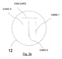
- Figs. 2a and 2b schematically shows the physical layout of cards within an SEM housing 12. For clarity, only three cards (i.e. "CARD 1" to "CARD 3") are shown in each bay's card stack.
- each electronics card is substantially planar, and in each of bays 1 and 2, CARD 1 to CARD 3 are arranged in a stack such that the major faces of each card are substantially parallel to, and coaxial with, major faces of the other cards in the stack.
- the ESB card holding the ESB switch blades 6 is orientated relative to the stack such that its major faces are substantially parallel to the axis of the stack and orthogonal to the major faces of the cards within the stack and positioned such that the ESB card is substantially equidistant from each card within the stack.
- SEM housing 12 is formed as an elongate cylinder, with a substantially circular cross section. Each stack is arranged with its axis orthogonal to the axis of the SEM housing 12.
- each ESB card occupies a segment cross-section space that exists above or below the card stack when installed in the SEM housing 12.
- the axis of the stacks may be parallel to the axis of the SEM housing 12.
Landscapes
- Engineering & Computer Science (AREA)
- Computer Networks & Wireless Communication (AREA)
- Physics & Mathematics (AREA)
- Life Sciences & Earth Sciences (AREA)
- Mining & Mineral Resources (AREA)
- Geology (AREA)
- Signal Processing (AREA)
- General Engineering & Computer Science (AREA)
- Theoretical Computer Science (AREA)
- General Physics & Mathematics (AREA)
- Fluid Mechanics (AREA)
- General Life Sciences & Earth Sciences (AREA)
- Geochemistry & Mineralogy (AREA)
- Environmental & Geological Engineering (AREA)
- Computer Hardware Design (AREA)
- Power Engineering (AREA)
- Connector Housings Or Holding Contact Members (AREA)
- Transceivers (AREA)
- Small-Scale Networks (AREA)
- Structure Of Telephone Exchanges (AREA)
- Mounting Of Printed Circuit Boards And The Like (AREA)
- Near-Field Transmission Systems (AREA)
- Financial Or Insurance-Related Operations Such As Payment And Settlement (AREA)
- Emergency Protection Circuit Devices (AREA)
Applications Claiming Priority (1)
| Application Number | Priority Date | Filing Date | Title |
|---|---|---|---|
| GB0823009.6A GB2466439B (en) | 2008-12-18 | 2008-12-18 | Subsea electronic device |
Publications (3)
| Publication Number | Publication Date |
|---|---|
| EP2199534A2 true EP2199534A2 (de) | 2010-06-23 |
| EP2199534A3 EP2199534A3 (de) | 2016-03-09 |
| EP2199534B1 EP2199534B1 (de) | 2022-12-28 |
Family
ID=40343744
Family Applications (1)
| Application Number | Title | Priority Date | Filing Date |
|---|---|---|---|
| EP09176532.1A Active EP2199534B1 (de) | 2008-12-18 | 2009-11-19 | Unterwasserelektronikmodul |
Country Status (7)
| Country | Link |
|---|---|
| US (2) | US8487779B2 (de) |
| EP (1) | EP2199534B1 (de) |
| AU (1) | AU2009250968B2 (de) |
| BR (1) | BRPI0905035A8 (de) |
| GB (2) | GB2466439B (de) |
| MY (2) | MY179483A (de) |
| SG (2) | SG162696A1 (de) |
Cited By (2)
| Publication number | Priority date | Publication date | Assignee | Title |
|---|---|---|---|---|
| EP2543811A1 (de) * | 2011-07-06 | 2013-01-09 | Vetco Gray Controls Limited | Unterwasserelektronikmodul |
| GB2579703A (en) * | 2018-12-03 | 2020-07-01 | Ge Oil & Gas Uk Ltd | Subsea communication network and communication methodology |
Families Citing this family (9)
| Publication number | Priority date | Publication date | Assignee | Title |
|---|---|---|---|---|
| EP2606545B1 (de) * | 2010-09-29 | 2014-12-17 | Siemens Aktiengesellschaft | Elektrischer unterwasserknoten |
| EP2853682A1 (de) * | 2013-09-25 | 2015-04-01 | Siemens Aktiengesellschaft | Unterwassergehäusesystem zur Beseitigung von erzeugter Hitze |
| US9820017B2 (en) * | 2014-08-06 | 2017-11-14 | Teledyne Instruments, Inc. | Subsea connector with data collection and communication system and method |
| GB2531031B (en) * | 2014-10-07 | 2021-04-07 | Aker Solutions Ltd | Apparatus |
| GB2531033B (en) * | 2014-10-07 | 2021-02-10 | Aker Solutions Ltd | An apparatus with wired electrical communication |
| GB2531032B (en) * | 2014-10-07 | 2021-01-06 | Aker Solutions Ltd | Subsea electronics module |
| EP3163013B1 (de) * | 2015-10-30 | 2018-09-19 | Siemens Aktiengesellschaft | Unterseekommunikationsadapter |
| US9832549B2 (en) | 2016-03-14 | 2017-11-28 | Teledyne Instruments, Inc. | System, method, and apparatus for subsea optical to electrical distribution |
| BR112019000789B1 (pt) | 2016-07-20 | 2022-09-06 | Halliburton Energy Services, Inc | Sistema de acoplamento capacitivo de fundo de poço, método para formar uma conexão elétrica entre duas colunas de fundo de poço e aparelho para fornecer uma conexão elétrica entre duas colunas de fundo de poço |
Family Cites Families (15)
| Publication number | Priority date | Publication date | Assignee | Title |
|---|---|---|---|---|
| DE4426908B4 (de) * | 1994-07-29 | 2004-05-19 | Vega Grieshaber Kg | Schaltungsanordnung mit kapazitiven Koppelelementen zur galvanischen Trennung zweier Signal-Stromkreise |
| WO2001080443A1 (de) * | 2000-04-18 | 2001-10-25 | Schleifring Und Apparatebau Gmbh | Anordnung zur kontaktlosen übertragung elektrischer signale bzw. energie zwischen mehreren ortsveränderlichen einheiten |
| US7200176B1 (en) * | 2001-07-06 | 2007-04-03 | Vitesse Semiconductor Corporation | Transformerless ethernet controller |
| US7088198B2 (en) * | 2002-06-05 | 2006-08-08 | Intel Corporation | Controlling coupling strength in electromagnetic bus coupling |
| US7242578B2 (en) * | 2003-05-20 | 2007-07-10 | Motorola, Inc. | N/2 slot switch module |
| US7261162B2 (en) * | 2003-06-25 | 2007-08-28 | Schlumberger Technology Corporation | Subsea communications system |
| US7239526B1 (en) * | 2004-03-02 | 2007-07-03 | Xilinx, Inc. | Printed circuit board and method of reducing crosstalk in a printed circuit board |
| EP1701384A1 (de) * | 2005-03-08 | 2006-09-13 | Sun Microsystems France S.A. | Netzwerkplanung mit Halbleiterchips für Gitternetzkommunikation |
| US7490189B2 (en) * | 2006-06-14 | 2009-02-10 | Sun Microsystems, Inc. | Multi-chip switch based on proximity communication |
| GB2443237B (en) * | 2006-08-17 | 2011-08-10 | Vetco Gray Controls Ltd | Communications system for an underwater fluid extraction facility |
| EP2149185B1 (de) * | 2007-04-13 | 2019-03-20 | OneSubsea IP UK Limited | Elektrisches versorgungssystem |
| GB0707334D0 (en) * | 2007-04-17 | 2007-05-23 | Kop Ltd | Indicating and detecting the start of signal transmission employing frequency division multiplexing |
| GB2451258A (en) * | 2007-07-25 | 2009-01-28 | Vetco Gray Controls Ltd | A wireless subsea electronic control module for a well installation |
| GB2460680B (en) * | 2008-06-05 | 2012-03-07 | Vetco Gray Controls Ltd | Subsea electronics module |
| GB2477331A (en) * | 2010-02-01 | 2011-08-03 | Vetco Gray Controls Ltd | Electronics module for underwater well installation having electronic components, relating to diverse systems. |
-
2008
- 2008-12-18 GB GB0823009.6A patent/GB2466439B/en active Active
- 2008-12-18 GB GB1505061.0A patent/GB2528527B8/en active Active
-
2009
- 2009-11-19 EP EP09176532.1A patent/EP2199534B1/de active Active
- 2009-12-16 AU AU2009250968A patent/AU2009250968B2/en active Active
- 2009-12-17 SG SG200908410-4A patent/SG162696A1/en unknown
- 2009-12-17 MY MYPI2012005688A patent/MY179483A/en unknown
- 2009-12-17 MY MYPI20095430A patent/MY158572A/en unknown
- 2009-12-17 US US12/640,220 patent/US8487779B2/en active Active
- 2009-12-17 BR BRPI0905035A patent/BRPI0905035A8/pt not_active Application Discontinuation
- 2009-12-17 SG SG2012043824A patent/SG182200A1/en unknown
-
2012
- 2012-01-24 US US13/356,992 patent/US8432294B2/en active Active
Non-Patent Citations (1)
| Title |
|---|
| None * |
Cited By (4)
| Publication number | Priority date | Publication date | Assignee | Title |
|---|---|---|---|---|
| EP2543811A1 (de) * | 2011-07-06 | 2013-01-09 | Vetco Gray Controls Limited | Unterwasserelektronikmodul |
| GB2579703A (en) * | 2018-12-03 | 2020-07-01 | Ge Oil & Gas Uk Ltd | Subsea communication network and communication methodology |
| GB2579703B (en) * | 2018-12-03 | 2021-03-10 | Baker Hughes Energy Technology UK Ltd | Subsea communication network and communication methodology |
| US12034489B2 (en) | 2018-12-03 | 2024-07-09 | Baker Hughes Energy Technology UK Limited | Subsea communication network and communication methodology |
Also Published As
| Publication number | Publication date |
|---|---|
| GB2466439B (en) | 2015-06-24 |
| EP2199534B1 (de) | 2022-12-28 |
| BRPI0905035A8 (pt) | 2016-04-12 |
| MY158572A (en) | 2016-10-14 |
| US8432294B2 (en) | 2013-04-30 |
| GB2466439A (en) | 2010-06-23 |
| US8487779B2 (en) | 2013-07-16 |
| BRPI0905035A2 (pt) | 2011-03-15 |
| GB2528527A8 (en) | 2016-09-21 |
| GB2528527A (en) | 2016-01-27 |
| AU2009250968A1 (en) | 2010-07-08 |
| GB2528527B (en) | 2016-05-11 |
| EP2199534A3 (de) | 2016-03-09 |
| US20120120963A1 (en) | 2012-05-17 |
| MY179483A (en) | 2020-11-08 |
| SG182200A1 (en) | 2012-07-30 |
| US20100156662A1 (en) | 2010-06-24 |
| SG162696A1 (en) | 2010-07-29 |
| AU2009250968B2 (en) | 2016-07-21 |
| GB2528527B8 (en) | 2016-09-21 |
| GB201505061D0 (en) | 2015-05-06 |
| GB0823009D0 (en) | 2009-01-28 |
Similar Documents
| Publication | Publication Date | Title |
|---|---|---|
| EP2199534B1 (de) | Unterwasserelektronikmodul | |
| EP2131639B1 (de) | Unterwasserelektronikmodul | |
| US8559183B1 (en) | Method to use empty slots in onboard aircraft servers and communication devices to install non-proprietary servers and communications interfaces | |
| US10498451B2 (en) | Removable module | |
| US10951325B1 (en) | Use of siilicon photonics (SiP) for computer network interfaces | |
| CN101188357B (zh) | 用于建筑设备的过压抑制系统 | |
| US9904330B2 (en) | Base board architecture for a server computer and method therefor | |
| EP2357313A2 (de) | Elektronisches Modul für ein Unterwasserbohrloch | |
| KR102480546B1 (ko) | 제어 포드, 보조 해저 시스템, 표면 제어부 간의 인터페이스를 위한 전력 및 통신 허브 | |
| US20030112582A1 (en) | Redundant data and power infrastructure for modular server components in a rack | |
| EP3638873B1 (de) | Unterwasserstromkabel und kommunikationsmodul | |
| US6817890B1 (en) | System and method for providing indicators within a connector assembly | |
| EP3342114B1 (de) | Kommunikationsknoten mit schnittstelle auf digitaler ebene | |
| KR20120002531A (ko) | Rfid 칩 기술을 사용하는 인터커넥트 구성에 대한 물리층 관리 | |
| US20180306007A1 (en) | Subsea open-standard control systems and methods | |
| US6554639B2 (en) | Wiring interface | |
| EP3163013A1 (de) | Unterseekommunikationsadapter | |
| CN120406678B (zh) | 一种供电系统及服务器 | |
| US20050250533A1 (en) | Wireless storage enterprise connectivity | |
| CN104067543A (zh) | 海底井控制系统中的通信 | |
| EP2606545B1 (de) | Elektrischer unterwasserknoten | |
| WO1998041730A1 (en) | Arrangement in a subsea production control system | |
| CN116567929A (zh) | 一种服务器的管理板及服务器 |
Legal Events
| Date | Code | Title | Description |
|---|---|---|---|
| PUAI | Public reference made under article 153(3) epc to a published international application that has entered the european phase |
Free format text: ORIGINAL CODE: 0009012 |
|
| AK | Designated contracting states |
Kind code of ref document: A2 Designated state(s): AT BE BG CH CY CZ DE DK EE ES FI FR GB GR HR HU IE IS IT LI LT LU LV MC MK MT NL NO PL PT RO SE SI SK SM TR |
|
| RAP1 | Party data changed (applicant data changed or rights of an application transferred) |
Owner name: GE OIL & GAS UK LIMITED |
|
| RIC1 | Information provided on ipc code assigned before grant |
Ipc: G06F 13/40 20060101ALI20150917BHEP Ipc: E21B 33/035 20060101AFI20150917BHEP |
|
| PUAL | Search report despatched |
Free format text: ORIGINAL CODE: 0009013 |
|
| RIC1 | Information provided on ipc code assigned before grant |
Ipc: E21B 33/035 20060101AFI20160120BHEP Ipc: G06F 13/40 20060101ALI20160120BHEP |
|
| AK | Designated contracting states |
Kind code of ref document: A3 Designated state(s): AT BE BG CH CY CZ DE DK EE ES FI FR GB GR HR HU IE IS IT LI LT LU LV MC MK MT NL NO PL PT RO SE SI SK SM TR |
|
| RIC1 | Information provided on ipc code assigned before grant |
Ipc: E21B 33/035 20060101AFI20160202BHEP Ipc: G06F 13/40 20060101ALI20160202BHEP |
|
| 17P | Request for examination filed |
Effective date: 20160909 |
|
| RBV | Designated contracting states (corrected) |
Designated state(s): AT BE BG CH CY CZ DE DK EE ES FI FR GB GR HR HU IE IS IT LI LT LU LV MC MK MT NL NO PL PT RO SE SI SK SM TR |
|
| STAA | Information on the status of an ep patent application or granted ep patent |
Free format text: STATUS: EXAMINATION IS IN PROGRESS |
|
| 17Q | First examination report despatched |
Effective date: 20190123 |
|
| RAP3 | Party data changed (applicant data changed or rights of an application transferred) |
Owner name: BAKER HUGHES ENERGY TECHNOLOGY UK LIMITED |
|
| REG | Reference to a national code |
Ref country code: DE Ref legal event code: R079 Ref document number: 602009064722 Country of ref document: DE Free format text: PREVIOUS MAIN CLASS: E21B0033035000 Ipc: H04B0005000000 |
|
| GRAP | Despatch of communication of intention to grant a patent |
Free format text: ORIGINAL CODE: EPIDOSNIGR1 |
|
| STAA | Information on the status of an ep patent application or granted ep patent |
Free format text: STATUS: GRANT OF PATENT IS INTENDED |
|
| RIC1 | Information provided on ipc code assigned before grant |
Ipc: H04L 12/40 20060101ALI20220905BHEP Ipc: H04B 5/00 20060101AFI20220905BHEP |
|
| GRAS | Grant fee paid |
Free format text: ORIGINAL CODE: EPIDOSNIGR3 |
|
| INTG | Intention to grant announced |
Effective date: 20221011 |
|
| GRAA | (expected) grant |
Free format text: ORIGINAL CODE: 0009210 |
|
| STAA | Information on the status of an ep patent application or granted ep patent |
Free format text: STATUS: THE PATENT HAS BEEN GRANTED |
|
| RBV | Designated contracting states (corrected) |
Designated state(s): AT BE BG CH CY CZ DE DK EE ES FI FR GR HR HU IE IS IT LI LT LU LV MC MK MT NL NO PL PT RO SE SI SK SM TR |
|
| AK | Designated contracting states |
Kind code of ref document: B1 Designated state(s): AT BE BG CH CY CZ DE DK EE ES FI FR GR HR HU IE IS IT LI LT LU LV MC MK MT NL NO PL PT RO SE SI SK SM TR |
|
| REG | Reference to a national code |
Ref country code: CH Ref legal event code: EP |
|
| REG | Reference to a national code |
Ref country code: DE Ref legal event code: R096 Ref document number: 602009064722 Country of ref document: DE |
|
| REG | Reference to a national code |
Ref country code: AT Ref legal event code: REF Ref document number: 1541118 Country of ref document: AT Kind code of ref document: T Effective date: 20230115 |
|
| REG | Reference to a national code |
Ref country code: IE Ref legal event code: FG4D |
|
| REG | Reference to a national code |
Ref country code: NO Ref legal event code: T2 Effective date: 20221228 |
|
| REG | Reference to a national code |
Ref country code: LT Ref legal event code: MG9D |
|
| PG25 | Lapsed in a contracting state [announced via postgrant information from national office to epo] |
Ref country code: SE Free format text: LAPSE BECAUSE OF FAILURE TO SUBMIT A TRANSLATION OF THE DESCRIPTION OR TO PAY THE FEE WITHIN THE PRESCRIBED TIME-LIMIT Effective date: 20221228 Ref country code: LT Free format text: LAPSE BECAUSE OF FAILURE TO SUBMIT A TRANSLATION OF THE DESCRIPTION OR TO PAY THE FEE WITHIN THE PRESCRIBED TIME-LIMIT Effective date: 20221228 Ref country code: FI Free format text: LAPSE BECAUSE OF FAILURE TO SUBMIT A TRANSLATION OF THE DESCRIPTION OR TO PAY THE FEE WITHIN THE PRESCRIBED TIME-LIMIT Effective date: 20221228 |
|
| REG | Reference to a national code |
Ref country code: NL Ref legal event code: MP Effective date: 20221228 |
|
| REG | Reference to a national code |
Ref country code: AT Ref legal event code: MK05 Ref document number: 1541118 Country of ref document: AT Kind code of ref document: T Effective date: 20221228 |
|
| PG25 | Lapsed in a contracting state [announced via postgrant information from national office to epo] |
Ref country code: LV Free format text: LAPSE BECAUSE OF FAILURE TO SUBMIT A TRANSLATION OF THE DESCRIPTION OR TO PAY THE FEE WITHIN THE PRESCRIBED TIME-LIMIT Effective date: 20221228 Ref country code: HR Free format text: LAPSE BECAUSE OF FAILURE TO SUBMIT A TRANSLATION OF THE DESCRIPTION OR TO PAY THE FEE WITHIN THE PRESCRIBED TIME-LIMIT Effective date: 20221228 Ref country code: GR Free format text: LAPSE BECAUSE OF FAILURE TO SUBMIT A TRANSLATION OF THE DESCRIPTION OR TO PAY THE FEE WITHIN THE PRESCRIBED TIME-LIMIT Effective date: 20230329 |
|
| PG25 | Lapsed in a contracting state [announced via postgrant information from national office to epo] |
Ref country code: NL Free format text: LAPSE BECAUSE OF FAILURE TO SUBMIT A TRANSLATION OF THE DESCRIPTION OR TO PAY THE FEE WITHIN THE PRESCRIBED TIME-LIMIT Effective date: 20221228 |
|
| P01 | Opt-out of the competence of the unified patent court (upc) registered |
Effective date: 20230526 |
|
| PG25 | Lapsed in a contracting state [announced via postgrant information from national office to epo] |
Ref country code: SM Free format text: LAPSE BECAUSE OF FAILURE TO SUBMIT A TRANSLATION OF THE DESCRIPTION OR TO PAY THE FEE WITHIN THE PRESCRIBED TIME-LIMIT Effective date: 20221228 Ref country code: RO Free format text: LAPSE BECAUSE OF FAILURE TO SUBMIT A TRANSLATION OF THE DESCRIPTION OR TO PAY THE FEE WITHIN THE PRESCRIBED TIME-LIMIT Effective date: 20221228 Ref country code: PT Free format text: LAPSE BECAUSE OF FAILURE TO SUBMIT A TRANSLATION OF THE DESCRIPTION OR TO PAY THE FEE WITHIN THE PRESCRIBED TIME-LIMIT Effective date: 20230428 Ref country code: ES Free format text: LAPSE BECAUSE OF FAILURE TO SUBMIT A TRANSLATION OF THE DESCRIPTION OR TO PAY THE FEE WITHIN THE PRESCRIBED TIME-LIMIT Effective date: 20221228 Ref country code: EE Free format text: LAPSE BECAUSE OF FAILURE TO SUBMIT A TRANSLATION OF THE DESCRIPTION OR TO PAY THE FEE WITHIN THE PRESCRIBED TIME-LIMIT Effective date: 20221228 Ref country code: CZ Free format text: LAPSE BECAUSE OF FAILURE TO SUBMIT A TRANSLATION OF THE DESCRIPTION OR TO PAY THE FEE WITHIN THE PRESCRIBED TIME-LIMIT Effective date: 20221228 Ref country code: AT Free format text: LAPSE BECAUSE OF FAILURE TO SUBMIT A TRANSLATION OF THE DESCRIPTION OR TO PAY THE FEE WITHIN THE PRESCRIBED TIME-LIMIT Effective date: 20221228 |
|
| PG25 | Lapsed in a contracting state [announced via postgrant information from national office to epo] |
Ref country code: SK Free format text: LAPSE BECAUSE OF FAILURE TO SUBMIT A TRANSLATION OF THE DESCRIPTION OR TO PAY THE FEE WITHIN THE PRESCRIBED TIME-LIMIT Effective date: 20221228 Ref country code: PL Free format text: LAPSE BECAUSE OF FAILURE TO SUBMIT A TRANSLATION OF THE DESCRIPTION OR TO PAY THE FEE WITHIN THE PRESCRIBED TIME-LIMIT Effective date: 20221228 Ref country code: IS Free format text: LAPSE BECAUSE OF FAILURE TO SUBMIT A TRANSLATION OF THE DESCRIPTION OR TO PAY THE FEE WITHIN THE PRESCRIBED TIME-LIMIT Effective date: 20230428 |
|
| REG | Reference to a national code |
Ref country code: DE Ref legal event code: R097 Ref document number: 602009064722 Country of ref document: DE |
|
| PG25 | Lapsed in a contracting state [announced via postgrant information from national office to epo] |
Ref country code: DK Free format text: LAPSE BECAUSE OF FAILURE TO SUBMIT A TRANSLATION OF THE DESCRIPTION OR TO PAY THE FEE WITHIN THE PRESCRIBED TIME-LIMIT Effective date: 20221228 |
|
| PLBE | No opposition filed within time limit |
Free format text: ORIGINAL CODE: 0009261 |
|
| STAA | Information on the status of an ep patent application or granted ep patent |
Free format text: STATUS: NO OPPOSITION FILED WITHIN TIME LIMIT |
|
| 26N | No opposition filed |
Effective date: 20230929 |
|
| PG25 | Lapsed in a contracting state [announced via postgrant information from national office to epo] |
Ref country code: SI Free format text: LAPSE BECAUSE OF FAILURE TO SUBMIT A TRANSLATION OF THE DESCRIPTION OR TO PAY THE FEE WITHIN THE PRESCRIBED TIME-LIMIT Effective date: 20221228 |
|
| PG25 | Lapsed in a contracting state [announced via postgrant information from national office to epo] |
Ref country code: IT Free format text: LAPSE BECAUSE OF FAILURE TO SUBMIT A TRANSLATION OF THE DESCRIPTION OR TO PAY THE FEE WITHIN THE PRESCRIBED TIME-LIMIT Effective date: 20221228 |
|
| REG | Reference to a national code |
Ref country code: CH Ref legal event code: PL |
|
| PG25 | Lapsed in a contracting state [announced via postgrant information from national office to epo] |
Ref country code: MC Free format text: LAPSE BECAUSE OF FAILURE TO SUBMIT A TRANSLATION OF THE DESCRIPTION OR TO PAY THE FEE WITHIN THE PRESCRIBED TIME-LIMIT Effective date: 20221228 |
|
| PG25 | Lapsed in a contracting state [announced via postgrant information from national office to epo] |
Ref country code: LU Free format text: LAPSE BECAUSE OF NON-PAYMENT OF DUE FEES Effective date: 20231119 |
|
| PG25 | Lapsed in a contracting state [announced via postgrant information from national office to epo] |
Ref country code: CH Free format text: LAPSE BECAUSE OF NON-PAYMENT OF DUE FEES Effective date: 20231130 |
|
| PG25 | Lapsed in a contracting state [announced via postgrant information from national office to epo] |
Ref country code: MC Free format text: LAPSE BECAUSE OF FAILURE TO SUBMIT A TRANSLATION OF THE DESCRIPTION OR TO PAY THE FEE WITHIN THE PRESCRIBED TIME-LIMIT Effective date: 20221228 Ref country code: LU Free format text: LAPSE BECAUSE OF NON-PAYMENT OF DUE FEES Effective date: 20231119 Ref country code: CH Free format text: LAPSE BECAUSE OF NON-PAYMENT OF DUE FEES Effective date: 20231130 |
|
| REG | Reference to a national code |
Ref country code: BE Ref legal event code: MM Effective date: 20231130 |
|
| REG | Reference to a national code |
Ref country code: IE Ref legal event code: MM4A |
|
| PG25 | Lapsed in a contracting state [announced via postgrant information from national office to epo] |
Ref country code: IE Free format text: LAPSE BECAUSE OF NON-PAYMENT OF DUE FEES Effective date: 20231119 |
|
| PG25 | Lapsed in a contracting state [announced via postgrant information from national office to epo] |
Ref country code: BE Free format text: LAPSE BECAUSE OF NON-PAYMENT OF DUE FEES Effective date: 20231130 |
|
| PG25 | Lapsed in a contracting state [announced via postgrant information from national office to epo] |
Ref country code: IE Free format text: LAPSE BECAUSE OF NON-PAYMENT OF DUE FEES Effective date: 20231119 Ref country code: BE Free format text: LAPSE BECAUSE OF NON-PAYMENT OF DUE FEES Effective date: 20231130 |
|
| PG25 | Lapsed in a contracting state [announced via postgrant information from national office to epo] |
Ref country code: BG Free format text: LAPSE BECAUSE OF FAILURE TO SUBMIT A TRANSLATION OF THE DESCRIPTION OR TO PAY THE FEE WITHIN THE PRESCRIBED TIME-LIMIT Effective date: 20221228 |
|
| PG25 | Lapsed in a contracting state [announced via postgrant information from national office to epo] |
Ref country code: BG Free format text: LAPSE BECAUSE OF FAILURE TO SUBMIT A TRANSLATION OF THE DESCRIPTION OR TO PAY THE FEE WITHIN THE PRESCRIBED TIME-LIMIT Effective date: 20221228 |
|
| PG25 | Lapsed in a contracting state [announced via postgrant information from national office to epo] |
Ref country code: HU Free format text: LAPSE BECAUSE OF FAILURE TO SUBMIT A TRANSLATION OF THE DESCRIPTION OR TO PAY THE FEE WITHIN THE PRESCRIBED TIME-LIMIT; INVALID AB INITIO Effective date: 20091119 |
|
| PG25 | Lapsed in a contracting state [announced via postgrant information from national office to epo] |
Ref country code: CY Free format text: LAPSE BECAUSE OF FAILURE TO SUBMIT A TRANSLATION OF THE DESCRIPTION OR TO PAY THE FEE WITHIN THE PRESCRIBED TIME-LIMIT; INVALID AB INITIO Effective date: 20091119 |
|
| PG25 | Lapsed in a contracting state [announced via postgrant information from national office to epo] |
Ref country code: TR Free format text: LAPSE BECAUSE OF FAILURE TO SUBMIT A TRANSLATION OF THE DESCRIPTION OR TO PAY THE FEE WITHIN THE PRESCRIBED TIME-LIMIT Effective date: 20221228 |
|
| PGFP | Annual fee paid to national office [announced via postgrant information from national office to epo] |
Ref country code: DE Payment date: 20251022 Year of fee payment: 17 |
|
| PGFP | Annual fee paid to national office [announced via postgrant information from national office to epo] |
Ref country code: NO Payment date: 20251024 Year of fee payment: 17 |
|
| PGFP | Annual fee paid to national office [announced via postgrant information from national office to epo] |
Ref country code: FR Payment date: 20251023 Year of fee payment: 17 |