EP2199448B1 - Verwendung einer Vorrichtung und Vorrichtung zur Erzeugung von Elastomervliesstofflaminaten - Google Patents
Verwendung einer Vorrichtung und Vorrichtung zur Erzeugung von Elastomervliesstofflaminaten Download PDFInfo
- Publication number
- EP2199448B1 EP2199448B1 EP10159702A EP10159702A EP2199448B1 EP 2199448 B1 EP2199448 B1 EP 2199448B1 EP 10159702 A EP10159702 A EP 10159702A EP 10159702 A EP10159702 A EP 10159702A EP 2199448 B1 EP2199448 B1 EP 2199448B1
- Authority
- EP
- European Patent Office
- Prior art keywords
- roller
- nonwoven
- drum
- nip
- strands
- Prior art date
- Legal status (The legal status is an assumption and is not a legal conclusion. Google has not performed a legal analysis and makes no representation as to the accuracy of the status listed.)
- Expired - Lifetime
Links
- 238000009826 distribution Methods 0.000 claims abstract description 10
- 239000004745 nonwoven fabric Substances 0.000 claims description 15
- 239000000853 adhesive Substances 0.000 claims description 13
- 230000001070 adhesive effect Effects 0.000 claims description 13
- 229920000642 polymer Polymers 0.000 claims description 10
- 238000005304 joining Methods 0.000 claims description 6
- 238000004519 manufacturing process Methods 0.000 abstract description 6
- 230000032258 transport Effects 0.000 abstract 1
- 239000000463 material Substances 0.000 description 16
- 239000000835 fiber Substances 0.000 description 9
- 238000000034 method Methods 0.000 description 7
- 238000001125 extrusion Methods 0.000 description 6
- -1 polypropylene Polymers 0.000 description 3
- LYCAIKOWRPUZTN-UHFFFAOYSA-N Ethylene glycol Chemical compound OCCO LYCAIKOWRPUZTN-UHFFFAOYSA-N 0.000 description 2
- 239000004743 Polypropylene Substances 0.000 description 2
- 230000009286 beneficial effect Effects 0.000 description 2
- 229920001971 elastomer Polymers 0.000 description 2
- 239000000806 elastomer Substances 0.000 description 2
- 238000010030 laminating Methods 0.000 description 2
- 238000003475 lamination Methods 0.000 description 2
- 229920001155 polypropylene Polymers 0.000 description 2
- 230000003068 static effect Effects 0.000 description 2
- 239000004677 Nylon Substances 0.000 description 1
- 239000004952 Polyamide Substances 0.000 description 1
- 239000004698 Polyethylene Substances 0.000 description 1
- 230000002745 absorbent Effects 0.000 description 1
- 239000002250 absorbent Substances 0.000 description 1
- 230000001133 acceleration Effects 0.000 description 1
- 230000004913 activation Effects 0.000 description 1
- 238000000418 atomic force spectrum Methods 0.000 description 1
- 229920002678 cellulose Polymers 0.000 description 1
- 239000001913 cellulose Substances 0.000 description 1
- 230000003749 cleanliness Effects 0.000 description 1
- 230000008602 contraction Effects 0.000 description 1
- 230000001747 exhibiting effect Effects 0.000 description 1
- 239000004744 fabric Substances 0.000 description 1
- 239000010408 film Substances 0.000 description 1
- 239000006260 foam Substances 0.000 description 1
- ZZUFCTLCJUWOSV-UHFFFAOYSA-N furosemide Chemical compound C1=C(Cl)C(S(=O)(=O)N)=CC(C(O)=O)=C1NCC1=CC=CO1 ZZUFCTLCJUWOSV-UHFFFAOYSA-N 0.000 description 1
- 238000010438 heat treatment Methods 0.000 description 1
- WGCNASOHLSPBMP-UHFFFAOYSA-N hydroxyacetaldehyde Natural products OCC=O WGCNASOHLSPBMP-UHFFFAOYSA-N 0.000 description 1
- 230000001788 irregular Effects 0.000 description 1
- 239000004816 latex Substances 0.000 description 1
- 229920000126 latex Polymers 0.000 description 1
- 239000011344 liquid material Substances 0.000 description 1
- 230000013011 mating Effects 0.000 description 1
- 239000012768 molten material Substances 0.000 description 1
- 229920001778 nylon Polymers 0.000 description 1
- 229920002647 polyamide Polymers 0.000 description 1
- 229920000728 polyester Polymers 0.000 description 1
- 229920000573 polyethylene Polymers 0.000 description 1
- 239000000843 powder Substances 0.000 description 1
- 238000009751 slip forming Methods 0.000 description 1
- 239000007787 solid Substances 0.000 description 1
- 239000000126 substance Substances 0.000 description 1
- 238000010408 sweeping Methods 0.000 description 1
- 238000011144 upstream manufacturing Methods 0.000 description 1
Images

Classifications
-
- B—PERFORMING OPERATIONS; TRANSPORTING
- B32—LAYERED PRODUCTS
- B32B—LAYERED PRODUCTS, i.e. PRODUCTS BUILT-UP OF STRATA OF FLAT OR NON-FLAT, e.g. CELLULAR OR HONEYCOMB, FORM
- B32B37/00—Methods or apparatus for laminating, e.g. by curing or by ultrasonic bonding
- B32B37/14—Methods or apparatus for laminating, e.g. by curing or by ultrasonic bonding characterised by the properties of the layers
- B32B37/144—Methods or apparatus for laminating, e.g. by curing or by ultrasonic bonding characterised by the properties of the layers using layers with different mechanical or chemical conditions or properties, e.g. layers with different thermal shrinkage, layers under tension during bonding
-
- B—PERFORMING OPERATIONS; TRANSPORTING
- B32—LAYERED PRODUCTS
- B32B—LAYERED PRODUCTS, i.e. PRODUCTS BUILT-UP OF STRATA OF FLAT OR NON-FLAT, e.g. CELLULAR OR HONEYCOMB, FORM
- B32B2305/00—Condition, form or state of the layers or laminate
- B32B2305/10—Fibres of continuous length
- B32B2305/20—Fibres of continuous length in the form of a non-woven mat
-
- B—PERFORMING OPERATIONS; TRANSPORTING
- B32—LAYERED PRODUCTS
- B32B—LAYERED PRODUCTS, i.e. PRODUCTS BUILT-UP OF STRATA OF FLAT OR NON-FLAT, e.g. CELLULAR OR HONEYCOMB, FORM
- B32B2307/00—Properties of the layers or laminate
- B32B2307/50—Properties of the layers or laminate having particular mechanical properties
- B32B2307/51—Elastic
-
- B—PERFORMING OPERATIONS; TRANSPORTING
- B32—LAYERED PRODUCTS
- B32B—LAYERED PRODUCTS, i.e. PRODUCTS BUILT-UP OF STRATA OF FLAT OR NON-FLAT, e.g. CELLULAR OR HONEYCOMB, FORM
- B32B37/00—Methods or apparatus for laminating, e.g. by curing or by ultrasonic bonding
- B32B37/12—Methods or apparatus for laminating, e.g. by curing or by ultrasonic bonding characterised by using adhesives
-
- Y—GENERAL TAGGING OF NEW TECHNOLOGICAL DEVELOPMENTS; GENERAL TAGGING OF CROSS-SECTIONAL TECHNOLOGIES SPANNING OVER SEVERAL SECTIONS OF THE IPC; TECHNICAL SUBJECTS COVERED BY FORMER USPC CROSS-REFERENCE ART COLLECTIONS [XRACs] AND DIGESTS
- Y10—TECHNICAL SUBJECTS COVERED BY FORMER USPC
- Y10T—TECHNICAL SUBJECTS COVERED BY FORMER US CLASSIFICATION
- Y10T156/00—Adhesive bonding and miscellaneous chemical manufacture
- Y10T156/17—Surface bonding means and/or assemblymeans with work feeding or handling means
- Y10T156/1702—For plural parts or plural areas of single part
- Y10T156/1712—Indefinite or running length work
- Y10T156/1722—Means applying fluent adhesive or adhesive activator material between layers
- Y10T156/1727—Plural indefinite length or running length workpieces
- Y10T156/1729—Fluid applied to nip between indefinite length webs
Definitions
- the present invention relates to the use of an apparatus for manufacturing an elastomeric nonwoven laminate and to an apparatus for producing a nonwoven elastomeric laminate. More particularly, the present invention relates to an apparatus for manufacturing an elastomeric nonwoven laminate comprising a plurality of elastic strands and nonwoven material.
- Disposable fluid-handling articles are often produced on high-speed converting lines using continuous webs of fabrics, films, foams, elastics, etc. Many of these articles preferably include an elastic region or component. Typically the elastic component is covered on at least one side, and preferably two sides, by a nonwoven. This combination of nonwoven and elastic is referred to hereinafter as an elastomeric nonwoven laminate.
- Elastomeric nonwoven laminates typically include elastic bonded to a nonwoven.
- the elastic may include elastic film or elastic strands, however, elastic strands are generally preferred over elastic films since strands require less material and provide flexibility in arrangement and stretch properties.
- a plurality of elastic strands is joined to a nonwoven while the plurality of strands is in a stretched condition so that when the elastic strands relax, the nonwoven gathers between the locations where it is bonded to the elastic strands forming corrugations.
- the resulting laminate is stretchable to the extent that the corrugations allow the elastic to elongate.
- Such a laminate is disclosed in U.S. Pat No. 4,720,415 to Vander Wielen, et al., issued January 19, 1988 .
- US 2002/019616 describes a process and apparatus whereby multiple elastics are transferred by multiple rolls to a nonwoven and then bonded thereto.
- Elastomeric nonwoven laminates with elastic strands may be produced by extruding a plurality of heated filaments onto a conveyor or roller where the filaments are cooled and transferred to a nonwoven.
- the plurality of strands may be unwound from a supply roll and joined to a nonwoven. In either case, arranging the strands uniformly on the nonwoven can be difficult.
- the elastic strands are typically transferred to the nonwoven and bonded by passing the combination through a nip formed between two rolls. During the transfer to the nonwoven, the elastic strands are typically unsupported. Due to vibrations and speed of operation, the strands tend to fall out of alignment, overlap, entangle, and bundle with neighboring strands. In addition the unsupported strands can break or stick to the conveyor and not transfer to the nonwoven at all. Broken strands can build up on equipment such as a conveyor or transfer roll which eventually results in downtime.
- the present invention provides the use of an apparatus for producing a nonwoven elastomeric laminate as in claim 1 and an apparatus for producing an elastomeric nonwoven laminate including a plurality of elastic strands bonded to a nonwoven web in a controlled distribution as in claim 2.
- the apparatus includes an extruder for extruding a plurality of elastic strands on a cooled surface of a drum, which conveys the plurality of strands to a first roller forming a nip with a second roller.
- the first nonwoven is supplied from a first nonwoven source to the second roller.
- the first roller is positioned close to the cooled surface of the drum to receive the plurality of elastic strands while allowing for a minimal span of unsupported strands during the transfer.
- the apparatus may include a second nonwoven source supplying a second nonwoven having a second bonding surface to the first roller forming the nip with the second roller.
- the plurality of elastic strands is conveyed directly onto the second bonding surface as the second nonwoven passes over the first roller.
- the first and second nonwovens pass through the nip in a face-to-face arrangement at second velocity V2 sandwiching the elastic strands therebetween conveyed from the cooled surface of the drum at first velocity V1 where V2 is greater than V1.
- the apparatus includes an idler roller located proximate to the cooled surface of the drum counterclockwise from the point where the plurality of strands are transferred to the first roller.
- the idler roller directs the first bonding surface of the first nonwoven into contact with the cooled surface of the drum enabling the first bonding surface to remove elastic strands that stick to the cooled surface of the drum and fail to transfer to the first roller.
- a pivot roller located adjacent to the second roller forming the nip, reverses the direction of the first nonwoven enabling any strands collected on the first bonding surface to be expelled therefrom.
- a series of rollers directs the first nonwoven first away from the pivot roller and then back around to the second roller forming the nip by first passing the first bonding surface beneath the pivot roller to recollect the elastic strands expelled at the pivot roller. Sweeping the cooled surface of the drum not only keeps the drum surface clean of elastic strands, but also provides a means for threading the plurality of elastic strands to the first roller during start up.
- An elastomeric nonwoven laminate comprising a first and second nonwoven sandwiching a plurality of elastic strands therebetween can be made to proceed from the nip to at least two pairs of rollers forming S-wraps.
- the first pair of rollers forming the S-wrap rotates at a speed providing a surface speed which is approximately equal to V2.
- the second pair of rollers forming the S-wrap rotates at a speed providing a surface speed V3 that is greater than V2.
- the acceleration overstrains the laminate resulting in additional stretch.
- an apparatus as in claim 1 and apparatus of the present invention as in claim 2 are designed to provide a more consumer desirable elastomeric nonwoven laminate suitable for use in a variety of articles including a disposable fluid-handling article.
- the elastomeric nonwoven laminate comprises a nonwoven and elastic composed from at least one layer of a plurality of elastic strands and at least one layer of a nonwoven material.
- the use of the apparatus and apparatus are capable of efficiently producing an elastomeric nonwoven laminate having a controlled distribution of elastic strands.
- Live stretch includes stretching elastic and bonding the stretched elastic to a nonwoven. After bonding the stretched elastic is released causing it to contract, resulting in a "corrugated” nonwoven.
- the corrugated nonwoven can stretch as the corrugated portion is pulled to about the point that the nonwoven reaches at least one original flat dimension.
- Continuous filaments refers to strands of continuously formed polymeric filaments. Such filaments are formed by extruding molten material through a die head having a certain type and arrangement of capillary holes therein.
- Controlled distribution refers to a parallel arrangement of elastic strands having no overlapping or bundles of strands where the variation in distance between the elastic strands from the point of extrusion to the point of lamination is minimal.
- a "converting facility” refers to any production equipment producing one or more components of a disposable fluid-handling article that are subsequently assembled into a finished disposable fluid-handling article. It may also produce a finished disposable fluid-handling article that is complete for use by a consumer.
- an “elastic,” “elastomer” or “elastomeric” refers to polymers exhibiting elastic properties. They include any material that upon application of a force to its relaxed, initial length can stretch or elongate to an elongated length more than 10% greater than its initial length and will substantially recover back to about its initial length upon release of the applied force.
- extrusion apparatus or “extruder” refers herein to any machine capable of extruding a molten stream of material such as a polymeric through one or more extrusion dies.
- extrude or “extruding” refers herein to a process by which a heated elastomer is forced through one or more extrusion dies to form a molten stream of elastic that cools into a solid.
- molten stream refers herein to a linear deposit of a heated liquid material such as a polymeric exiting an extrusion apparatus.
- the stream may include continuous filaments, discontinuous fibers, or continuous films of a polymeric material.
- the molten stream forms an elastic strand.
- joind herein encompasses configurations whereby a material or component is secured directly or indirectly (by one or more intermediate members) to another material or component.
- An example of indirect joining is an adhesive.
- Direct bonding includes heat and or pressure bonding.
- Joining may include any means known in the art including, for example, adhesives, heat bonds, pressure bonds, ultrasonic bonds, and the like.
- nonwoven refers herein to a material made from continuous (long) filaments (fibers) and/or discontinuous (short) filaments (fibers) by processes such as spunbonding, meltblowing, and the like.
- Nonwovens do not have a woven or knitted filament pattern.
- Nonwovens are typically described as having a machine direction and a cross direction.
- the machine direction is the direction in which the nonwoven is manufactured.
- the cross direction is the direction perpendicular to the machine direction.
- Nonwovens are typically formed with a machine direction that corresponds to the long or rolled direction of fabrication.
- the machine direction is also the primary direction of fiber orientation in the nonwoven.
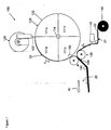
- FIG. 1 shows a side view of an apparatus 100 according to the present invention for producing elastomeric nonwoven laminate 20.
- the apparatus 100 includes a drum 110 rotating about an axis 114 and having a surface speed V 1 .
- the drum 110 is glycol cooled to provide a cooled external surface 112. The temperature of the cooled external surface is maintained between 0°C and 5°C.
- the drum 110 has a first quadrant 111a between 12 o'clock and 3 o'clock, a second quadrant 111b between 3 o'clock and 6 o'clock, a third quadrant 111c between 6 o'clock and 9 o'clock, and a fourth quadrant 111d between 9 o'clock and 12 o'clock.
- the drum 110 can be sized to accommodate any size laminate or process set up. For instance a larger drum 110 may be utilized for offline material production operations where the elastomeric nonwoven laminate is stored on a roll or in a box for future use. Smaller drum sizes may be required for online operations incorporated upstream of a converting operation. For offline operations, the diameter of the drum may be approximately one meter or larger, whereas for online operations the diameter of the drum may be approximately 0.5 meters or less. Similarly for offline operations, the width of the drum may be approximately one meter or larger whereas for online operations the width of the drum may be limited to approximately one meter or less.
- the rotation of the drum 110 can be powered by a variable speed motor capable of ramping up or down depending on the operator's demand.
- the apparatus 100 includes an extruder 120 for extruding a molten stream of elastomeric polymer.
- the extruder 120 extrudes the molten stream of polymer through a plurality of nozzles 122 forming a plurality of elastic strands 23 that flow in parallel alignment onto the cooled surface 112 of the rotating drum 110.
- the elastic strands are extruded onto the cooled surface 112 of the drum 110 such that the distance between any two adjacent strands ranges between 1 mm and 3 mm. More preferably, the distance between any two adjacent strands is 1.5 mm.
- the extruder 120 is mounted between the first and fourth quadrants 111a, 111d and deposits the plurality of strands 23 onto the cooled surface 112 of the drum 110 near 12:00 o'clock.
- the extruder 120 preferably includes a built in metering pump, valve and nozzle arrangement wherein the metering pump and valve are positioned in proximity to the nozzle in order to provide a controlled discharge of polymer.
- the controlled discharge of polymer ensures that an adequate supply of polymer is supplied to the cooled surface of the drum particularly during starts and stops. Excessive flow of polymer during stops can cause localized heating of the cooled surface of the drum which can lead to polymer build up caused by the elastic strands sticking to the surface of the drum.
- First and second rollers 130, 132 are mounted near the cooled surface 112 of the drum 110 at the third quadrant 111c.
- the first and second rollers 130, 132 rotate about two parallel axes forming a nip 134 therebetween, where each provides a surface speed V2.
- the surface speed V2 of each of the rollers is greater than the surface speed V1 of the drum.
- the first roller 130 is positioned proximate to the cooled surface 112 of the drum 110 to minimize the span 150 of unsupported strands transferring from the cooled surface 112 of the drum 110 to the first roller 130.
- the first roller is positioned as close to the cooled surface of the drum as possible without actually making contact.
- the actual measured distance separating the two depends upon the sizes of the drum and the first roller. For instance, for a drum diameter of 1 meter and a first roller diameter of 150 mm, the distance between the cooled surface 112 of the drum 110 and the first roller 130 can range from approximately 0.5 mm to 5 mm.
- the corresponding length of the span 150 of unsupported strands can range from 18 mm to 75 mm.
- the length of the span 150 of unsupported strands can be shorter.
- a 0.5 meter diameter drum with a 150 mm first roller 130 can enable the first roller 130 to be positioned as close as 1 mm to the cooled surface 112 of the drum 110 and limit the length of the span 150 of unsupported strands to 22 mm.
- the first roller 130 receives the plurality of strands 23 near the cooled surface 112 of the drum 110, minimizing the span 150 of unsupported strands between the cooled surface 112 of the drum 110 and the first roller 130.
- the plurality of strands 23 transfers from the cooled surface 112 of the drum 110 to the first roller such that the strands are approximately tangent to both the cooled surface of the drum and the surface of the first roller 130 and the length of the span 150 of unsupported elastic strands 23 is minimal, ranging between 10 mm and 200 mm.
- the length of the span 150 of unsupported elastic strands 23 during the transfer ranges between 20 mm and 50 mm.
- the elastic strands can be transferred to the first roller in a controlled distribution where the distance measured between any two adjacent strands varies 30% or less from the point of extrusion to the point of lamination. For instance, if the original spacing at the extruder is set atl mm, the spacing between any two adjacent strands will range between 0.7 mm to 1.3 mm.
- a first nonwoven source 140 supplies a first nonwoven 21 having a first bonding surface 32 to the second roller 132 forming the nip 134 with the first roller 130.
- a first adhesive source 142 positioned between the first nonwoven source 140 and the second roller 132 applies adhesive to the first bonding surface 22.
- the first nonwoven 21 and the plurality of elastic strands 23 pass between the nip 134 formed by the first and second rollers 130, 132 forming the laminate.
- the difference in velocity between surface velocity V1 of the cooled surface 112 of the drum 110 and the surface velocity V2 of the first and second rollers 130, 132 strains the plurality of elastic strands 23 at the nip. Once the strain is relieved from the strands, corrugations form in the nonwoven providing an elastomeric nonwoven laminate 20.
- the elastomeric nonwoven laminate 20 may be conveyed directly to a converting operation which manipulates the laminate to form a component of a disposable absorbent article such as an elastic waist band, an elastic cuff or an elastic side panel.
- the elastomeric nonwoven laminate 20 may be joined with a second nonwoven or other material and stored on a roll or in a box for future use.
- Exposed adhesive on the first bonding surface 22 between the elastic strands 23 resulting from the process of joining the plurality of strands 23 to the first bonding surface 22 can hinder any down stream converting operation and can make storing the elastomeric nonwoven laminate on a roll virtually impossible. Consequently, it is preferred to cover the elastic strands 23 that are exposed on the first bonding surface 22 of the first nonwoven 21.
- Such covering may include a flexible release paper joined to the first bonding surface 22 downstream of the nip 134. The release paper can enable the laminate to be stored on a roll and can be removed in a subsequent operation.
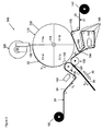
- a second nonwoven source 160 may be provided supplying a second nonwoven 24 to be joined with the first nonwoven 21 and plurality of elastic strands 23.
- the second nonwoven source 160 supplies a second nonwoven 24 having a second bonding surface 25 to the first roller 130 forming the nip 134 with the second roller 132.
- the first and second nonwovens 21, 24 pass between the nip 134 formed by the first and second rollers 130, 132 sandwiching the plurality of elastic strands 23 therebetween.
- a first strain is produced on the elastic strands 23 as a result of being extended in the machine direction 40.
- the strain is induced as a result of the difference in velocity between the elastic strands 23 traveling on the cooled surface 112 of the drum 110 at first velocity V1 and the first and second nonwovens 21, 24 traveling on the second and first rollers 132, 130, respectively, at second velocity V2.
- the difference in velocity creates a strain on the plurality of elastic strands 23 ranging from 20% to 500%.
- the extensibility of the elastomeric nonwoven laminate can be further enhanced by overstraining the web.
- the elastomeric nonwoven laminate 20 is exposed to a second strain by passing the laminate through at least two pairs of rotating rollers 210, 220 forming S wraps downstream of the nip 134.
- the first pair of rollers 210 forming the first S wrap 212 provides a surface speed V2
- the second pair of rollers 220 forming the second S wrap 222 provides a surface speed V3 which is greater than V2.
- the increase in velocity experienced by the laminate as it is conveyed through the S wraps 212, 222 overstrains the laminate 20 which can increase the extensibility of the laminate at least 20%
- an idler roller 170 is positioned between the first nonwoven source 140 and the second roller 132, which is disposed adjacent to the second quadrant 111b of the cooled surface 112 of the drum 110.
- the idler roller 170 directs the first bonding surface 22 of the first nonwoven 21 into contact with the cooled surface 112 of the drum 110 in advance of reaching the second roller 132.
- the first bonding surface 22 can remove elastic strands that stick to the cooled surface 112 of the drum 110 and fail to transfer to the nip 134 formed by the first and second rollers 130, 132.
- the first nonwoven 21 can be made to proceed to a pivot roller 180 located adjacent to the second roller 132 forming the nip 134, a select distance from the idler roller 170.
- the pivot roller 180 can be arranged to force the first nonwoven 21 in a reverse direction near the second roller 132 causing any stray strands collected from the cooled surface 112 of the drum 110 to expel from the first bonding surface 22.
- the pivot roller is preferably small having a diameter which is less than 20 mm.
- the pivot roller can be replaced with a static plate or sheet, however, a roller is preferred since a static plate or sheet can induce strain on the nonwoven causing necking.
- the first nonwoven 24 can be made to proceed to a series of rollers 190.
- the series of rollers 190 are arranged relative to the pivot roller 180 such that the angle 185 between first nonwoven 21 approaching the pivot roller 180 and the first nonwoven 21 departing the pivot roller 180 ranges from 0 degrees to 90 degrees.
- the series of rollers 190 directs the first nonwoven 21 first away from the pivot roller 180 and then back to the second roller 132 forming the nip 134 along a path which passes the first bonding surface 22 beneath the pivot roller 180 so that any strands expelled from the first bonding surface 22 at the pivot roller 180 can be recollected onto the first bonding surface 22 prior to reaching the second roller 132.
- the series of rollers 190 can also be arranged to direct the first nonwoven 21 to a first adhesive applicator 142 applying a first adhesive to the first bonding surface 22 prior to passing beneath the pivot roller 180.
- Forcing the first bonding surface 22 of the first nonwoven 21 to make contact with the cooled surface 112 of the drum 110 in the second quadrant 111b has other advantages such as enabling the apparatus to automatically thread itself during initial start up.
- the elastic strands 23 are not heavy enough to automatically separate from the cooled surface 112 of the drum 110 and transfer to the first roller 130. As a result, the elastic strands 23 stick to the cooled surface 112 of the drum 110, bypassing the first roller 130 in the third quadrant 111c.
- the elastic strands 23 are removed from the cooled surface 112 of the drum 110 and redirected to the nip 134 formed between the first and second rollers 130, 132.
- the plurality of elastic strands 23 sandwiched between the first and second nonwovens 21, 24 are exposed to a second strain by passing the elastomeric laminate through at least two pairs of rotating rollers 200 forming S wraps positioned downstream of the nip 134.
- the first pair of rollers 210 forming the first S wrap 212 provides a surface speed V2 and the second pair of rollers 220 forming the second S wrap 222 provides a surface speed V3 that is greater than V2.
- the increase in velocity overstrains the laminate 20 which can increase the extensibility of the laminate at least 20%.
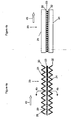
- Figure 4a shows, in exaggerated form, the corrugation of the first and second nonwovens 21, 24 with corrugation hills 28 and corrugation valleys 29 that occur after the first and second nonwovens 21, 24 are joined to the elastic strands 23. Corrugation is used to describe irregular corrugation hills 28 and corrugation valleys 29 that alternate. As shown, the first and second nonwovens 21, 24 are corrugated in the cross direction 45 with the corrugation hills 28 and corrugation valleys 29 alternating in the machine direction 40.
- the corrugations enable the first and second nonwovens 21, 24 to extend with the plurality of elastic strands 23 at-least-to -the-point-of reaching the-force-wall, which is about where the corrugations flatten out.
- the plurality of elastic strands 23 contract back toward their original, relaxed length. This contraction causes the observed first and second nonwoven 21, 24 corrugations.
- Strain is measured as the percent of length increase in the plurality of elastic strands 23 under load.
- a strand with a free and stretchable strand length of 15 centimeters (cm) may have a load applied such that the 15 cm strand elastic is now 18 cm long. This length increase of 3 cm is 20% of 15 cm (3/15), or a 20% strain.
- the elastomeric nonwoven 20 produced according to the present application may have a strain ranging from 20% to 500%, preferably from 100% to 400%, and more preferably from 200% to 400%.
- the elastomeric nonwoven laminate 20 Since the primary function of the elastomeric nonwoven laminate 20 is to be stretchable, the elastomeric nonwoven laminate 20 is capable of at least a 50% strain prior to reaching the force wall. Although the force wall has generally been described as the point where the corrugations nearly flatten out, the force wall typically occurs when the force required for a 10% increase in strain increases at least about 20%. Depending upon design choice and the particular application of the elastomeric nonwoven laminate, the elastomeric nonwoven laminate 20 can be made to endure a strain greater than 50%, 100%, 200%, or 300% prior to reaching the force wall. Preferably, the elastomeric nonwoven laminate 20 produced according to the present application is capable of at least a 100% strain prior to reaching the force wall. More preferably, the elastomeric nonwoven laminate 20 is capable of at least a 200% strain prior to reaching the force wall.
- the first nonwoven 21 and the second nonwoven 24 may comprise any nonwoven material known in the art.
- the first nonwoven 21 and the second nonwoven 24 may comprise fibers made of polypropylene, polyethylene, polyester, nylon, cellulose, polyamide, or combinations of such materials. Fibers of one material or fibers of different materials or material combinations may be used in the first and/or second nonwoven 21, 24.
- any process known in the art may be used to make the first nonwoven 21 and/or the second nonwoven 24.
- Exemplary processes include spunbond, spunbond meltblown spunbond (SMS), spunbond meltblown meltblown spunbond (SMMS), carded and the like.
- Particularly acceptable nonwovens include high elongation carded (HEC) nonwovens and deep activation polypropylene (DAPP) nonwovens.
- the first nonwoven 21 and the second nonwoven 24 may comprise fibers that are bonded internally, including fibers that are needle punched, hydro entangled, spun bonded, thermally bonded, bonded by various types of chemical bonding such as latex bonding, powder bonding, and the like.
- the basis weight of the first nonwoven 21 and/or second nonwoven 24 is in the range of 10 gsm to 30 gsm.
- the elastic strands 23 preferably extend in a parallel uniformly spaced arrangement between the first nonwoven 21 and the second nonwoven 24.
- the elastic strands 23 may be arranged in any configuration desired.
- the strands may be arranged to provide a specific force profile in the elastomeric nonwoven laminate 20 by varying the thickness of the individual strands or the spacing between them.
- the shape of the elastic strands 23 is not limited.
- typical elastic strands 23 have a circular cross sectional shape, but sometimes the plurality of elastic strands may have different shapes, such as a trilobal shape, or a flat (i.e., "ribbon" like) shape.
- the thickness or diameter of the elastic strands 23 may vary in order to accommodate a particular application.
Landscapes
- Engineering & Computer Science (AREA)
- Mechanical Engineering (AREA)
- Laminated Bodies (AREA)
- Nonwoven Fabrics (AREA)
Claims (13)
- Verwendung einer Vorrichtung für die Herstellung eines elastomeren Vlieslaminats, das aus mindestens einem Vlies und mehreren elastischen Fäden besteht, wobei die Vorrichtung Folgendes umfasst:a) eine oberflächengekühlte Trommel, die sich um eine Achse dreht und eine Oberflächengeschwindigkeit V1 aufweist, wobei die oberflächengekühlte Trommel einen ersten Quadranten zwischen 12 Uhr und 3 Uhr, einen zweiten Quadranten zwischen 3 Uhr und 6 Uhr, einen dritten Quadranten zwischen 6 Uhr und 9 Uhr und einen vierten Quadranten zwischen 9 Uhr und 12 Uhr aufweist,b) eine Strangpresse, die mehrere parallel ausgerichtete elastomere Fäden auf die gekühlte Oberfläche der Trommel zwischen dem ersten und dem zweiten Quadranten extrudiert,c) erste und zweite Walzen, die einen Walzenspalt dazwischen bilden, wobei die erste Walze nahe der gekühlten Oberfläche der Trommel positioniert ist, wobei die erste und zweite Walze jeweils eine Oberflächengeschwindigkeit V2 aufweisen, wobei die Oberflächengeschwindigkeit V2 größer ist als die Oberflächengeschwindigkeit V1,d) eine erste Vliesquelle, die ein erstes Vlies mit einer ersten Verbindungsfläche zur zweiten Walze, die den Walzenspalt bildet, führt, unde) eine erste Klebstoffquelle zum Auftragen von Klebstoff auf die erste Verbindungsfläche vor dem Walzenspalt,f) eine Spannwalze, die zwischen der ersten Vliesquelle und der zweiten Walze angrenzend an die gekühlte Oberfläche der Trommel angeordnet ist, wobei die Spannwalze die erste Verbindungsfläche so führt, dass sie die gekühlte Oberfläche der Trommel berührt,
wobei die Trommel die mehreren elastischen Fasern zur ersten Walze überträgt und
wobei die Spannweite der ungestützten Fasern zwischen der gekühlten Oberfläche der Trommel und der ersten Walze minimiert wird, um eine gesteuerte Verteilung der elastischen Fasern, die in den Walzenspalt eintreten und mit der ersten Verbindungsfläche des ersten Vlieses verbunden werden, bereitzustellen, und
wobei die erste Verbindungsfläche, die von der Spannwalze so geführt wird, dass sie die gekühlte Oberfläche der Trommel berührt, Fasern von der gekühlten Oberfläche der Trommel entfernt, die versehentlich nicht auf die erste Walze, die den Walzenspalt bildet, übertragen wurden. - Vorrichtung für die Herstellung eines elastomeren Vlieslaminats, das aus mindestens einem Vlies und mehreren elastischen Fasern besteht, wobei die Vorrichtung Folgendes umfassta) eine oberflächengekühlte Trommel, die sich um eine Achse dreht und eine Oberflächengeschwindigkeit V1 aufweist, wobei die oberflächengekühlte Trommel einen ersten Quadranten zwischen 12 Uhr und 3 Uhr, einen zweiten Quadranten zwischen 3 Uhr und 6 Uhr, einen dritten Quadranten zwischen 6 Uhr und 9 Uhr und einen vierten Quadranten zwischen 9 Uhr und 12 Uhr aufweist,b) eine Strangpresse, die mehrere parallel ausgerichtete elastomere Fasern auf die abgekühlte Oberfläche der Trommel zwischen dem ersten und dem zweiten Quadranten extrudiert,c) erste und zweite Walzen, die einen Walzenspalt dazwischen bilden, wobei die erste Walze nahe der gekühlten Oberfläche der Trommel positioniert ist, wobei die erste und zweite Walze jeweils eine Oberflächengeschwindigkeit V2 aufweisen, wobei die Oberflächengeschwindigkeit V2 größer ist als die Oberflächengeschwindigkeit V1,d) eine erste Vliesquelle, die ein erstes Vlies mit einer ersten Verbindungsfläche zur zweiten Walze, die den Walzenspalt bildet, führt, unde) eine erste Klebstoffquelle zum Auftragen von Klebstoff auf die erste Verbindungsfläche vor dem Walzenspalt,f) eine Spannwalze, die zwischen der ersten Vliesquelle und der zweiten Walze angrenzend an die gekühlte Oberfläche der Trommel positioniert ist, wobei die Spannwalze die erste Verbindungsfläche so führt, dass sie die gekühlte Oberfläche der Trommel berührt, um von der gekühlten Oberfläche der Trommel Fasern zu entfernen, die versehentlich nicht zur ersten Walze, die den Walzenspalt bildet, übertragen wurden,
wobei die Trommel die mehreren elastischen Fasern zur ersten Walze überträgt und
wobei die Spannweite der ungestützten Fasern zwischen der gekühlten Oberfläche der Trommel und der ersten Walze minimiert ist, um eine gesteuerte Verteilung der elastischen Fasern, die in den Walzenspalt eintreten und mit der ersten Verbindungsfläche des ersten Vlieses verbunden werden, bereitzustellen. - Vorrichtung nach Anspruch 2, wobei die Vorrichtung zusätzlich Folgendes umfasst:g) eine Zapfenwalze, die in einem ausgewählten Abstand von der Spannwalze an die zweite Walze, die den Walzenspalt bildet, angrenzt, wobei die Zapfenwalze einen Richtungswechsel des ersten Vlieses nahe der zweiten Walze ermöglicht, wodurch die von der gekühlten Oberfläche der Trommel gesammelten Fasern von der ersten Verbindungsfläche abgestoßen werden können, undh) eine Walzenreihe, die nahe der Zapfenwalze positioniert ist, wobei die Walzenreihe so angeordnet ist, dass sie das erste Vlies von der Zapfenwalze weg und dann zurück zur zweiten Walze, die den Walzenspalt bildet, führt, während die erste Verbindungsfläche unterhalb der Zapfenwalze läuft, um die zerrissenen elastischen Fasern aufzufangen, die an der Zapfenwalze auf die erste Verbindungsfläche vor dem Eintritt in den Walzenspalt abgestoßen wurden.
- Vorrichtung nach Anspruch 3, wobei bei der Vorrichtung die Spannwalze und die Zapfenwalze so aufeinanderfolgend angeordnet sind, dass die erste Verbindungsfläche des ersten Vlieses die gekühlte Oberfläche der Trommel im zweiten Quadranten zwischen der Spannwalze und der Zapfenwalze berührt.
- Vorrichtung nach Anspruch 4, wobei bei der Vorrichtung die Walzenreihe im Verhältnis zur Zapfenwalze so angeordnet ist, dass der Winkel zwischen dem ersten Vlies, das sich der Zapfenwalze nähert, und dem ersten Vlies, das aus der Zapfenwalze austritt, im Bereich von 0 Grad bis 90 Grad liegt.
- Vorrichtung nach Anspruch 1 oder 2, wobei die Spannweite so minimiert ist, dass sie zwischen 10 mm und 200 mm oder vorzugsweise zwischen 20 mm und 50 mm liegt.
- Vorrichtung nach Anspruch 2 oder 6, wobei die Spannweite der ungestützten Fasern zwischen der gekühlten Oberfläche der Trommel und der ersten Walze sowohl die gekühlte Oberfläche der Trommel als auch die erste Walze tangiert.
- Vorrichtung nach Anspruch 2 oder 6 oder 7, wobei ein Abstand, der zwischen zwei beliebigen, benachbarten elastischen Fasern, die mit der ersten Verbindungsfläche des ersten Vlieses verbunden sind, gemessen wird, um weniger als 30 % von dem Abstand variiert, der zwischen den gleichen aneinander angrenzenden elastischen Fasern, die aus der Strangpresse in paralleler Ausrichtung auf die gekühlte Oberfläche der Trommel extrudiert werden, gemessen wird.
- Vorrichtung nach Anspruch 2, 6, 7 oder 8, wobei die elastischen Fasern mit einem Abstand zwischen benachbarten elastomeren Fasern zwischen 1 mm und 3 mm auf die gekühlte Oberfläche extrudiert werden.
- Vorrichtung nach Anspruch 2, wobei die Strangpresse der Vorrichtung eine eingebaute Messpumpen-, Ventil- und Düsenanordnung umfasst, wobei die Messpumpe und das Ventil nahe der Düse positioniert sind, um für eine gesteuerte Polymerabgabe zu sorgen und somit den Polymerfluss während der Anlauf- und Haltevorgänge einzuschränken.
- Vorrichtung nach Anspruch 2, wobei die Vorrichtung ferner eine zweite Vliesquelle umfasst, die ein zweites Vlies mit einer zweiten Verbindungsfläche zur ersten Walze, die den Walzenspalt bildet, führt, wobei die erste und die zweite Verbindungsfläche des ersten und des zweiten Vlieses in einer einander zugewandten Anordnung am Walzenspalt, der die mehreren elastischen Fasern in einer gesteuerten Verteilung dazwischen umschließt, miteinander verbunden werden.
- Vorrichtung nach Anspruch 11, wobei die Vorrichtung ferner eine zweite Klebstoffquelle umfasst, die sich zwischen der zweiten Vliesquelle und der ersten Walze, die den Walzenspalt bildet, befindet, um auf die zweite Verbindungsfläche vor dem Erreichen des Walzenspalts Klebstoff aufzutragen.
- Vorrichtung nach Anspruch 11, wobei die Vorrichtung ferner mindestens zwei Paar Walzen umfasst, die zwei S-förmige Wickel bilden, die auf den Walzenspalt folgend angeordnet sind, wobei die Drehung des ersten Walzenpaars eine Oberflächengeschwindigkeit V2 ergibt und wobei die Drehung des zweiten Walzenpaars eine Oberflächengeschwindigkeit V3 ergibt, die größer ist als V2, wobei die S-förmigen Wickel das elastomere Vlieslaminat überdehnen, wodurch die Dehnbarkeit um mindestens 20 % erhöht wird.
Applications Claiming Priority (2)
| Application Number | Priority Date | Filing Date | Title |
|---|---|---|---|
| US10/452,438 US7028735B2 (en) | 2003-06-02 | 2003-06-02 | Method and apparatus for producing elastomeric nonwoven laminates |
| EP04776213A EP1629145B1 (de) | 2003-06-02 | 2004-06-02 | Vorrichtung zur herstellung von elastomerischen vliesschichtstoffen |
Related Parent Applications (1)
| Application Number | Title | Priority Date | Filing Date |
|---|---|---|---|
| EP04776213.3 Division | 2004-06-02 |
Publications (3)
| Publication Number | Publication Date |
|---|---|
| EP2199448A2 EP2199448A2 (de) | 2010-06-23 |
| EP2199448A3 EP2199448A3 (de) | 2010-08-04 |
| EP2199448B1 true EP2199448B1 (de) | 2011-08-17 |
Family
ID=33451999
Family Applications (3)
| Application Number | Title | Priority Date | Filing Date |
|---|---|---|---|
| EP10157522A Expired - Lifetime EP2202340B1 (de) | 2003-06-02 | 2004-06-02 | Verwendung einer Vorrichtung zur Herstellung von Elastomervlieslaminaten |
| EP04776213A Expired - Lifetime EP1629145B1 (de) | 2003-06-02 | 2004-06-02 | Vorrichtung zur herstellung von elastomerischen vliesschichtstoffen |
| EP10159702A Expired - Lifetime EP2199448B1 (de) | 2003-06-02 | 2004-06-02 | Verwendung einer Vorrichtung und Vorrichtung zur Erzeugung von Elastomervliesstofflaminaten |
Family Applications Before (2)
| Application Number | Title | Priority Date | Filing Date |
|---|---|---|---|
| EP10157522A Expired - Lifetime EP2202340B1 (de) | 2003-06-02 | 2004-06-02 | Verwendung einer Vorrichtung zur Herstellung von Elastomervlieslaminaten |
| EP04776213A Expired - Lifetime EP1629145B1 (de) | 2003-06-02 | 2004-06-02 | Vorrichtung zur herstellung von elastomerischen vliesschichtstoffen |
Country Status (7)
| Country | Link |
|---|---|
| US (2) | US7028735B2 (de) |
| EP (3) | EP2202340B1 (de) |
| JP (1) | JP2006525895A (de) |
| CN (1) | CN100340399C (de) |
| AT (3) | ATE520521T1 (de) |
| MX (1) | MXPA05012777A (de) |
| WO (1) | WO2004110749A2 (de) |
Families Citing this family (34)
| Publication number | Priority date | Publication date | Assignee | Title |
|---|---|---|---|---|
| DE10108092B4 (de) * | 2001-02-19 | 2007-01-04 | Carl Freudenberg Kg | Verfahren zur Herstellung eines Tuftingträgers |
| WO2005079720A1 (ja) * | 2004-02-23 | 2005-09-01 | Zuiko Corporation | 着用物品およびその製造方法 |
| US7222654B2 (en) * | 2004-04-30 | 2007-05-29 | The Procter & Gamble Company | Apparatus for producing elastomeric nonwoven laminates |
| US8910689B2 (en) * | 2005-03-15 | 2014-12-16 | The Procter & Gamble Company | Apparatus for reducing downtime in web processes |
| US7744579B2 (en) | 2005-06-29 | 2010-06-29 | The Procter & Gamble Company | Absorbent article providing a better fit and more comfort to a wearer |
| US20070128094A1 (en) * | 2005-12-02 | 2007-06-07 | Arjo Wiggins | Microbial barrier system having a plurality of sterilization sheets |
| BRPI0708300B1 (pt) * | 2006-03-03 | 2017-01-24 | Toho Tenax Europe Gmbh | processos para a fabricação de estruturas, e para a fabricação de um material compósito reforçado com fibra |
| US20070255246A1 (en) * | 2006-04-28 | 2007-11-01 | The Procter & Gamble Company | Disposable absorbent articles with reinforced seams |
| US9072633B2 (en) | 2006-06-07 | 2015-07-07 | The Procter & Gamble Company | Biaxially stretchable outer cover for an absorbent article |
| US20080114326A1 (en) * | 2006-11-15 | 2008-05-15 | Donald Carroll Roe | Disposable absorbent article having a wrap and tuck configuration |
| BRPI0718770A2 (pt) * | 2006-11-29 | 2013-12-03 | Procter & Gamble | Substratos com padrões impressos sobre os mesmos proporcionando uma aparência tridimensional |
| MX2009007420A (es) * | 2007-01-10 | 2009-07-17 | Procter & Gamble | Articulos absorbentes desechables para llevar puestos, con lados extensibles. |
| US8790325B2 (en) | 2007-09-07 | 2014-07-29 | The Procter & Gamble Company | Disposable wearable absorbent articles with anchoring subsystems |
| US9060900B2 (en) | 2007-09-07 | 2015-06-23 | The Proctor & Gamble Company | Disposable wearable absorbent articles with anchoring subsystems |
| US9056031B2 (en) | 2007-09-07 | 2015-06-16 | The Procter & Gamble Company | Disposable wearable absorbent articles with anchoring subsystems |
| US8858523B2 (en) | 2007-09-07 | 2014-10-14 | The Procter & Gamble Company | Disposable wearable absorbent articles with anchoring subsystems |
| US8597268B2 (en) | 2007-09-07 | 2013-12-03 | The Procter & Gamble Company | Disposable wearable absorbent articles with anchoring subsystems |
| US20090069777A1 (en) * | 2007-09-07 | 2009-03-12 | Andrew James Sauer | Disposable wearable absorbent articles with anchoring subsystems |
| US8668679B2 (en) * | 2007-09-07 | 2014-03-11 | The Procter & Gamble Company | Disposable wearable absorbent articles with anchoring subsystems |
| US8945079B2 (en) | 2007-09-07 | 2015-02-03 | The Procter & Gamble Company | Disposable wearable absorbent articles with anchoring subsystems |
| EP2211805B1 (de) | 2007-11-19 | 2011-08-17 | The Procter & Gamble Company | Verfahren zur aktivierung einer bahn |
| US20090294044A1 (en) | 2008-05-27 | 2009-12-03 | Nathan Alan Gill | Methods and Apparatus for Attaching Elastic Components to Absorbent Articles |
| US8333748B2 (en) | 2009-03-05 | 2012-12-18 | The Procter & Gamble Company | Outer cover for a disposable absorbent article |
| CA2692679C (en) * | 2010-02-25 | 2013-04-30 | The Procter & Gamble Company | Absorbent article with improved garment-like character |
| CA2692638C (en) * | 2010-02-25 | 2011-05-10 | The Procter & Gamble Company | Absorbent article with improved garment-like character |
| CA2693130C (en) * | 2010-02-25 | 2012-10-09 | The Procter & Gamble Company | Absorbent article with improved garment-like character |
| CA2692891C (en) * | 2010-02-25 | 2012-10-09 | The Procter & Gamble Company | Absorbent article with improved garment-like character |
| US20120029454A1 (en) | 2010-07-27 | 2012-02-02 | Wenbin Li | Absorbent Articles with Printed Graphics Thereon Providing A Three-Dimensional Appearance |
| CN102490415A (zh) * | 2011-11-14 | 2012-06-13 | 成都彩虹环保科技有限公司 | 多层弹性复合材料及其制造装置 |
| US9532908B2 (en) | 2013-09-20 | 2017-01-03 | The Procter & Gamble Company | Textured laminate surface, absorbent articles with textured laminate structure, and for manufacturing |
| US20150083310A1 (en) | 2013-09-20 | 2015-03-26 | The Procter & Gamble Company | Textured Laminate Structure, Absorbent Articles With Textured Laminate Structure, And Method for Manufacturing |
| WO2015047805A1 (en) * | 2013-09-27 | 2015-04-02 | The Procter & Gamble Company | Apparatus and method for isolating a broken elastic strand |
| JP5753883B2 (ja) * | 2013-10-18 | 2015-07-22 | ユニ・チャーム株式会社 | 吸収性物品に係るシート状部材の製造装置、及び製造方法 |
| CN110215353A (zh) * | 2019-07-15 | 2019-09-10 | 泉州市嘉佰利卫生材料有限公司 | 一种采用新型橡筋复合结构的纸尿裤及其生产工艺 |
Family Cites Families (20)
| Publication number | Priority date | Publication date | Assignee | Title |
|---|---|---|---|---|
| US3468748A (en) | 1965-04-14 | 1969-09-23 | Johnson & Johnson | Nonwoven fabric with machine direction elasticity |
| US3575782A (en) | 1967-05-19 | 1971-04-20 | Minnesota Mining & Mfg | Elastic shirred web product |
| US3648748A (en) * | 1969-08-18 | 1972-03-14 | Goodyear Tire & Rubber | Tire having polyurethane laminate thereon |
| US4917746A (en) * | 1982-06-21 | 1990-04-17 | Kons Hugo L | Apparatus and method for contouring elastic ribbon on disposable garments |
| US4720415A (en) | 1985-07-30 | 1988-01-19 | Kimberly-Clark Corporation | Composite elastomeric material and process for making the same |
| US5143679A (en) | 1991-02-28 | 1992-09-01 | The Procter & Gamble Company | Method for sequentially stretching zero strain stretch laminate web to impart elasticity thereto without rupturing the web |
| US5156793A (en) | 1991-02-28 | 1992-10-20 | The Procter & Gamble Company | Method for incrementally stretching zero strain stretch laminate web in a non-uniform manner to impart a varying degree of elasticity thereto |
| US5167897A (en) | 1991-02-28 | 1992-12-01 | The Procter & Gamble Company | Method for incrementally stretching a zero strain stretch laminate web to impart elasticity thereto |
| CA2106461A1 (en) | 1991-03-20 | 1992-09-21 | Reinhardt N. Sabee | Elasticized fabric with continuous filaments and method of forming |
| US6194532B1 (en) | 1991-10-15 | 2001-02-27 | The Dow Chemical Company | Elastic fibers |
| US5385775A (en) | 1991-12-09 | 1995-01-31 | Kimberly-Clark Corporation | Composite elastic material including an anisotropic elastic fibrous web and process to make the same |
| US5693165A (en) | 1993-11-04 | 1997-12-02 | The Procter & Gamble Company | Method and apparatus for manufacturing an absorbent article |
| US5681302A (en) | 1994-06-14 | 1997-10-28 | Minnesota Mining And Manufacturing Company | Elastic sheet-like composite |
| US5814178A (en) * | 1995-06-30 | 1998-09-29 | Kimberly-Clark Worldwide, Inc. | Process for making a bulked fabric laminate |
| US5964973A (en) * | 1998-01-21 | 1999-10-12 | Kimberly-Clark Worldwide, Inc. | Method and apparatus for making an elastomeric laminate web |
| US20020119722A1 (en) | 2000-05-15 | 2002-08-29 | Welch Howard M. | Elastic stranded laminate with adhesive bonds and method of manufacture |
| US6969441B2 (en) * | 2000-05-15 | 2005-11-29 | Kimberly-Clark Worldwide, Inc. | Method and apparatus for producing laminated articles |
| US20020019616A1 (en) * | 2000-05-15 | 2002-02-14 | Thomas Oomman Painumoottil | Elastomeric laminate with film and strands suitable for a nonwoven garment |
| US6833179B2 (en) * | 2000-05-15 | 2004-12-21 | Kimberly-Clark Worldwide, Inc. | Targeted elastic laminate having zones of different basis weights |
| US6916750B2 (en) * | 2003-03-24 | 2005-07-12 | Kimberly-Clark Worldwide, Inc. | High performance elastic laminates made from high molecular weight styrenic tetrablock copolymer |
-
2003
- 2003-06-02 US US10/452,438 patent/US7028735B2/en not_active Expired - Lifetime
-
2004
- 2004-06-02 EP EP10157522A patent/EP2202340B1/de not_active Expired - Lifetime
- 2004-06-02 AT AT10159702T patent/ATE520521T1/de not_active IP Right Cessation
- 2004-06-02 EP EP04776213A patent/EP1629145B1/de not_active Expired - Lifetime
- 2004-06-02 MX MXPA05012777A patent/MXPA05012777A/es active IP Right Grant
- 2004-06-02 CN CNB2004800142469A patent/CN100340399C/zh not_active Expired - Fee Related
- 2004-06-02 AT AT10157522T patent/ATE520522T1/de not_active IP Right Cessation
- 2004-06-02 AT AT04776213T patent/ATE518981T1/de not_active IP Right Cessation
- 2004-06-02 WO PCT/US2004/017254 patent/WO2004110749A2/en not_active Ceased
- 2004-06-02 EP EP10159702A patent/EP2199448B1/de not_active Expired - Lifetime
- 2004-06-02 JP JP2006515060A patent/JP2006525895A/ja active Pending
-
2006
- 2006-03-17 US US11/378,053 patent/US7476288B2/en not_active Expired - Fee Related
Also Published As
| Publication number | Publication date |
|---|---|
| EP2202340A2 (de) | 2010-06-30 |
| JP2006525895A (ja) | 2006-11-16 |
| WO2004110749A2 (en) | 2004-12-23 |
| EP2202340B1 (de) | 2011-08-17 |
| ATE518981T1 (de) | 2011-08-15 |
| CN1795098A (zh) | 2006-06-28 |
| US7028735B2 (en) | 2006-04-18 |
| US7476288B2 (en) | 2009-01-13 |
| ATE520521T1 (de) | 2011-09-15 |
| US20040238105A1 (en) | 2004-12-02 |
| EP1629145B1 (de) | 2011-08-03 |
| MXPA05012777A (es) | 2006-02-13 |
| EP2202340A3 (de) | 2010-08-04 |
| US20060175001A1 (en) | 2006-08-10 |
| EP2199448A2 (de) | 2010-06-23 |
| EP2199448A3 (de) | 2010-08-04 |
| EP1629145A2 (de) | 2006-03-01 |
| CN100340399C (zh) | 2007-10-03 |
| WO2004110749A3 (en) | 2005-03-24 |
| ATE520522T1 (de) | 2011-09-15 |
Similar Documents
| Publication | Publication Date | Title |
|---|---|---|
| EP2199448B1 (de) | Verwendung einer Vorrichtung und Vorrichtung zur Erzeugung von Elastomervliesstofflaminaten | |
| EP1750935B1 (de) | Vorrichtung zur herstellung von elastomeren vlieslaminaten | |
| US20060288547A1 (en) | Zoned stretching of a web | |
| US10913253B2 (en) | Manufacturing process for elastomeric laminate |
Legal Events
| Date | Code | Title | Description |
|---|---|---|---|
| PUAI | Public reference made under article 153(3) epc to a published international application that has entered the european phase |
Free format text: ORIGINAL CODE: 0009012 |
|
| AC | Divisional application: reference to earlier application |
Ref document number: 1629145 Country of ref document: EP Kind code of ref document: P |
|
| AK | Designated contracting states |
Kind code of ref document: A2 Designated state(s): AT BE BG CH CY CZ DE DK EE ES FI FR GB GR HU IE IT LI LU MC NL PL PT RO SE SI SK TR |
|
| PUAL | Search report despatched |
Free format text: ORIGINAL CODE: 0009013 |
|
| AK | Designated contracting states |
Kind code of ref document: A3 Designated state(s): AT BE BG CH CY CZ DE DK EE ES FI FR GB GR HU IE IT LI LU MC NL PL PT RO SE SI SK TR |
|
| 17P | Request for examination filed |
Effective date: 20110119 |
|
| REG | Reference to a national code |
Ref country code: DE Ref legal event code: R079 Ref document number: 602004034050 Country of ref document: DE Free format text: PREVIOUS MAIN CLASS: D04H0013000000 Ipc: B32B0005040000 |
|
| GRAP | Despatch of communication of intention to grant a patent |
Free format text: ORIGINAL CODE: EPIDOSNIGR1 |
|
| RIC1 | Information provided on ipc code assigned before grant |
Ipc: B32B 5/26 20060101ALI20110310BHEP Ipc: D04H 3/04 20060101ALI20110310BHEP Ipc: B32B 5/04 20060101AFI20110310BHEP Ipc: D04H 13/00 20060101ALI20110310BHEP |
|
| RTI1 | Title (correction) |
Free format text: USE OF AN APPARATUS AND APPARATUS FOR PRODUCING ELASTOMERIC NONWOVEN LAMINATES |
|
| GRAS | Grant fee paid |
Free format text: ORIGINAL CODE: EPIDOSNIGR3 |
|
| GRAA | (expected) grant |
Free format text: ORIGINAL CODE: 0009210 |
|
| AC | Divisional application: reference to earlier application |
Ref document number: 1629145 Country of ref document: EP Kind code of ref document: P |
|
| AK | Designated contracting states |
Kind code of ref document: B1 Designated state(s): AT BE BG CH CY CZ DE DK EE ES FI FR GB GR HU IE IT LI LU MC NL PL PT RO SE SI SK TR |
|
| REG | Reference to a national code |
Ref country code: GB Ref legal event code: FG4D |
|
| REG | Reference to a national code |
Ref country code: CH Ref legal event code: EP |
|
| REG | Reference to a national code |
Ref country code: IE Ref legal event code: FG4D |
|
| REG | Reference to a national code |
Ref country code: DE Ref legal event code: R096 Ref document number: 602004034050 Country of ref document: DE Effective date: 20111013 |
|
| REG | Reference to a national code |
Ref country code: NL Ref legal event code: VDEP Effective date: 20110817 |
|
| PG25 | Lapsed in a contracting state [announced via postgrant information from national office to epo] |
Ref country code: FI Free format text: LAPSE BECAUSE OF FAILURE TO SUBMIT A TRANSLATION OF THE DESCRIPTION OR TO PAY THE FEE WITHIN THE PRESCRIBED TIME-LIMIT Effective date: 20110817 Ref country code: SE Free format text: LAPSE BECAUSE OF FAILURE TO SUBMIT A TRANSLATION OF THE DESCRIPTION OR TO PAY THE FEE WITHIN THE PRESCRIBED TIME-LIMIT Effective date: 20110817 Ref country code: NL Free format text: LAPSE BECAUSE OF FAILURE TO SUBMIT A TRANSLATION OF THE DESCRIPTION OR TO PAY THE FEE WITHIN THE PRESCRIBED TIME-LIMIT Effective date: 20110817 Ref country code: PT Free format text: LAPSE BECAUSE OF FAILURE TO SUBMIT A TRANSLATION OF THE DESCRIPTION OR TO PAY THE FEE WITHIN THE PRESCRIBED TIME-LIMIT Effective date: 20111219 |
|
| REG | Reference to a national code |
Ref country code: AT Ref legal event code: MK05 Ref document number: 520521 Country of ref document: AT Kind code of ref document: T Effective date: 20110817 |
|
| PG25 | Lapsed in a contracting state [announced via postgrant information from national office to epo] |
Ref country code: SI Free format text: LAPSE BECAUSE OF FAILURE TO SUBMIT A TRANSLATION OF THE DESCRIPTION OR TO PAY THE FEE WITHIN THE PRESCRIBED TIME-LIMIT Effective date: 20110817 Ref country code: CY Free format text: LAPSE BECAUSE OF FAILURE TO SUBMIT A TRANSLATION OF THE DESCRIPTION OR TO PAY THE FEE WITHIN THE PRESCRIBED TIME-LIMIT Effective date: 20110817 Ref country code: AT Free format text: LAPSE BECAUSE OF FAILURE TO SUBMIT A TRANSLATION OF THE DESCRIPTION OR TO PAY THE FEE WITHIN THE PRESCRIBED TIME-LIMIT Effective date: 20110817 Ref country code: GR Free format text: LAPSE BECAUSE OF FAILURE TO SUBMIT A TRANSLATION OF THE DESCRIPTION OR TO PAY THE FEE WITHIN THE PRESCRIBED TIME-LIMIT Effective date: 20111118 Ref country code: PL Free format text: LAPSE BECAUSE OF FAILURE TO SUBMIT A TRANSLATION OF THE DESCRIPTION OR TO PAY THE FEE WITHIN THE PRESCRIBED TIME-LIMIT Effective date: 20110817 |
|
| PG25 | Lapsed in a contracting state [announced via postgrant information from national office to epo] |
Ref country code: BE Free format text: LAPSE BECAUSE OF FAILURE TO SUBMIT A TRANSLATION OF THE DESCRIPTION OR TO PAY THE FEE WITHIN THE PRESCRIBED TIME-LIMIT Effective date: 20110817 |
|
| PG25 | Lapsed in a contracting state [announced via postgrant information from national office to epo] |
Ref country code: SK Free format text: LAPSE BECAUSE OF FAILURE TO SUBMIT A TRANSLATION OF THE DESCRIPTION OR TO PAY THE FEE WITHIN THE PRESCRIBED TIME-LIMIT Effective date: 20110817 Ref country code: CZ Free format text: LAPSE BECAUSE OF FAILURE TO SUBMIT A TRANSLATION OF THE DESCRIPTION OR TO PAY THE FEE WITHIN THE PRESCRIBED TIME-LIMIT Effective date: 20110817 |
|
| PG25 | Lapsed in a contracting state [announced via postgrant information from national office to epo] |
Ref country code: EE Free format text: LAPSE BECAUSE OF FAILURE TO SUBMIT A TRANSLATION OF THE DESCRIPTION OR TO PAY THE FEE WITHIN THE PRESCRIBED TIME-LIMIT Effective date: 20110817 Ref country code: RO Free format text: LAPSE BECAUSE OF FAILURE TO SUBMIT A TRANSLATION OF THE DESCRIPTION OR TO PAY THE FEE WITHIN THE PRESCRIBED TIME-LIMIT Effective date: 20110817 Ref country code: IT Free format text: LAPSE BECAUSE OF FAILURE TO SUBMIT A TRANSLATION OF THE DESCRIPTION OR TO PAY THE FEE WITHIN THE PRESCRIBED TIME-LIMIT Effective date: 20110817 |
|
| PLBE | No opposition filed within time limit |
Free format text: ORIGINAL CODE: 0009261 |
|
| STAA | Information on the status of an ep patent application or granted ep patent |
Free format text: STATUS: NO OPPOSITION FILED WITHIN TIME LIMIT |
|
| PG25 | Lapsed in a contracting state [announced via postgrant information from national office to epo] |
Ref country code: DK Free format text: LAPSE BECAUSE OF FAILURE TO SUBMIT A TRANSLATION OF THE DESCRIPTION OR TO PAY THE FEE WITHIN THE PRESCRIBED TIME-LIMIT Effective date: 20110817 |
|
| 26N | No opposition filed |
Effective date: 20120521 |
|
| REG | Reference to a national code |
Ref country code: DE Ref legal event code: R097 Ref document number: 602004034050 Country of ref document: DE Effective date: 20120521 |
|
| PG25 | Lapsed in a contracting state [announced via postgrant information from national office to epo] |
Ref country code: MC Free format text: LAPSE BECAUSE OF NON-PAYMENT OF DUE FEES Effective date: 20120630 |
|
| REG | Reference to a national code |
Ref country code: CH Ref legal event code: PL |
|
| REG | Reference to a national code |
Ref country code: CH Ref legal event code: PL |
|
| REG | Reference to a national code |
Ref country code: IE Ref legal event code: MM4A |
|
| PG25 | Lapsed in a contracting state [announced via postgrant information from national office to epo] |
Ref country code: ES Free format text: LAPSE BECAUSE OF FAILURE TO SUBMIT A TRANSLATION OF THE DESCRIPTION OR TO PAY THE FEE WITHIN THE PRESCRIBED TIME-LIMIT Effective date: 20111128 Ref country code: LI Free format text: LAPSE BECAUSE OF NON-PAYMENT OF DUE FEES Effective date: 20120630 Ref country code: IE Free format text: LAPSE BECAUSE OF NON-PAYMENT OF DUE FEES Effective date: 20120602 Ref country code: CH Free format text: LAPSE BECAUSE OF NON-PAYMENT OF DUE FEES Effective date: 20120630 |
|
| PG25 | Lapsed in a contracting state [announced via postgrant information from national office to epo] |
Ref country code: BG Free format text: LAPSE BECAUSE OF FAILURE TO SUBMIT A TRANSLATION OF THE DESCRIPTION OR TO PAY THE FEE WITHIN THE PRESCRIBED TIME-LIMIT Effective date: 20111117 |
|
| PG25 | Lapsed in a contracting state [announced via postgrant information from national office to epo] |
Ref country code: TR Free format text: LAPSE BECAUSE OF FAILURE TO SUBMIT A TRANSLATION OF THE DESCRIPTION OR TO PAY THE FEE WITHIN THE PRESCRIBED TIME-LIMIT Effective date: 20110817 |
|
| PG25 | Lapsed in a contracting state [announced via postgrant information from national office to epo] |
Ref country code: LU Free format text: LAPSE BECAUSE OF NON-PAYMENT OF DUE FEES Effective date: 20120602 |
|
| PG25 | Lapsed in a contracting state [announced via postgrant information from national office to epo] |
Ref country code: HU Free format text: LAPSE BECAUSE OF FAILURE TO SUBMIT A TRANSLATION OF THE DESCRIPTION OR TO PAY THE FEE WITHIN THE PRESCRIBED TIME-LIMIT Effective date: 20040602 |
|
| PGFP | Annual fee paid to national office [announced via postgrant information from national office to epo] |
Ref country code: FR Payment date: 20140527 Year of fee payment: 11 |
|
| REG | Reference to a national code |
Ref country code: FR Ref legal event code: ST Effective date: 20160229 |
|
| PG25 | Lapsed in a contracting state [announced via postgrant information from national office to epo] |
Ref country code: FR Free format text: LAPSE BECAUSE OF NON-PAYMENT OF DUE FEES Effective date: 20150630 |
|
| PGFP | Annual fee paid to national office [announced via postgrant information from national office to epo] |
Ref country code: GB Payment date: 20170531 Year of fee payment: 14 Ref country code: DE Payment date: 20170530 Year of fee payment: 14 |
|
| REG | Reference to a national code |
Ref country code: DE Ref legal event code: R119 Ref document number: 602004034050 Country of ref document: DE |
|
| GBPC | Gb: european patent ceased through non-payment of renewal fee |
Effective date: 20180602 |
|
| PG25 | Lapsed in a contracting state [announced via postgrant information from national office to epo] |
Ref country code: GB Free format text: LAPSE BECAUSE OF NON-PAYMENT OF DUE FEES Effective date: 20180602 Ref country code: DE Free format text: LAPSE BECAUSE OF NON-PAYMENT OF DUE FEES Effective date: 20190101 |