EP2199431A1 - A hydrogen-oxygen generating apparatus - Google Patents
A hydrogen-oxygen generating apparatus Download PDFInfo
- Publication number
- EP2199431A1 EP2199431A1 EP09275119A EP09275119A EP2199431A1 EP 2199431 A1 EP2199431 A1 EP 2199431A1 EP 09275119 A EP09275119 A EP 09275119A EP 09275119 A EP09275119 A EP 09275119A EP 2199431 A1 EP2199431 A1 EP 2199431A1
- Authority
- EP
- European Patent Office
- Prior art keywords
- electrolyte
- electric pole
- cover
- hydrogen
- thin walled
- Prior art date
- Legal status (The legal status is an assumption and is not a legal conclusion. Google has not performed a legal analysis and makes no representation as to the accuracy of the status listed.)
- Withdrawn
Links
Images


Classifications
-
- C—CHEMISTRY; METALLURGY
- C25—ELECTROLYTIC OR ELECTROPHORETIC PROCESSES; APPARATUS THEREFOR
- C25B—ELECTROLYTIC OR ELECTROPHORETIC PROCESSES FOR THE PRODUCTION OF COMPOUNDS OR NON-METALS; APPARATUS THEREFOR
- C25B9/00—Cells or assemblies of cells; Constructional parts of cells; Assemblies of constructional parts, e.g. electrode-diaphragm assemblies; Process-related cell features
- C25B9/17—Cells comprising dimensionally-stable non-movable electrodes; Assemblies of constructional parts thereof
-
- F—MECHANICAL ENGINEERING; LIGHTING; HEATING; WEAPONS; BLASTING
- F02—COMBUSTION ENGINES; HOT-GAS OR COMBUSTION-PRODUCT ENGINE PLANTS
- F02M—SUPPLYING COMBUSTION ENGINES IN GENERAL WITH COMBUSTIBLE MIXTURES OR CONSTITUENTS THEREOF
- F02M25/00—Engine-pertinent apparatus for adding non-fuel substances or small quantities of secondary fuel to combustion-air, main fuel or fuel-air mixture
- F02M25/10—Engine-pertinent apparatus for adding non-fuel substances or small quantities of secondary fuel to combustion-air, main fuel or fuel-air mixture adding acetylene, non-waterborne hydrogen, non-airborne oxygen, or ozone
- F02M25/12—Engine-pertinent apparatus for adding non-fuel substances or small quantities of secondary fuel to combustion-air, main fuel or fuel-air mixture adding acetylene, non-waterborne hydrogen, non-airborne oxygen, or ozone the apparatus having means for generating such gases
-
- C—CHEMISTRY; METALLURGY
- C25—ELECTROLYTIC OR ELECTROPHORETIC PROCESSES; APPARATUS THEREFOR
- C25B—ELECTROLYTIC OR ELECTROPHORETIC PROCESSES FOR THE PRODUCTION OF COMPOUNDS OR NON-METALS; APPARATUS THEREFOR
- C25B1/00—Electrolytic production of inorganic compounds or non-metals
- C25B1/01—Products
- C25B1/02—Hydrogen or oxygen
-
- C—CHEMISTRY; METALLURGY
- C25—ELECTROLYTIC OR ELECTROPHORETIC PROCESSES; APPARATUS THEREFOR
- C25B—ELECTROLYTIC OR ELECTROPHORETIC PROCESSES FOR THE PRODUCTION OF COMPOUNDS OR NON-METALS; APPARATUS THEREFOR
- C25B1/00—Electrolytic production of inorganic compounds or non-metals
- C25B1/01—Products
- C25B1/02—Hydrogen or oxygen
- C25B1/04—Hydrogen or oxygen by electrolysis of water
-
- Y—GENERAL TAGGING OF NEW TECHNOLOGICAL DEVELOPMENTS; GENERAL TAGGING OF CROSS-SECTIONAL TECHNOLOGIES SPANNING OVER SEVERAL SECTIONS OF THE IPC; TECHNICAL SUBJECTS COVERED BY FORMER USPC CROSS-REFERENCE ART COLLECTIONS [XRACs] AND DIGESTS
- Y02—TECHNOLOGIES OR APPLICATIONS FOR MITIGATION OR ADAPTATION AGAINST CLIMATE CHANGE
- Y02E—REDUCTION OF GREENHOUSE GAS [GHG] EMISSIONS, RELATED TO ENERGY GENERATION, TRANSMISSION OR DISTRIBUTION
- Y02E60/00—Enabling technologies; Technologies with a potential or indirect contribution to GHG emissions mitigation
- Y02E60/30—Hydrogen technology
- Y02E60/36—Hydrogen production from non-carbon containing sources, e.g. by water electrolysis
-
- Y—GENERAL TAGGING OF NEW TECHNOLOGICAL DEVELOPMENTS; GENERAL TAGGING OF CROSS-SECTIONAL TECHNOLOGIES SPANNING OVER SEVERAL SECTIONS OF THE IPC; TECHNICAL SUBJECTS COVERED BY FORMER USPC CROSS-REFERENCE ART COLLECTIONS [XRACs] AND DIGESTS
- Y02—TECHNOLOGIES OR APPLICATIONS FOR MITIGATION OR ADAPTATION AGAINST CLIMATE CHANGE
- Y02T—CLIMATE CHANGE MITIGATION TECHNOLOGIES RELATED TO TRANSPORTATION
- Y02T10/00—Road transport of goods or passengers
- Y02T10/10—Internal combustion engine [ICE] based vehicles
- Y02T10/12—Improving ICE efficiencies
Definitions
- the present invention is about a hydrogen-oxygen generator that can produce hydrogen-oxygen mixture effectively from water.
- Hydrogen-oxygen mixed-gas generating system is made to produce hydrogen and oxygen from electrolyzed water; to gain hydrogen-oxygen mixed gas, water containing small amount of electrolytes is provided to the storage with positive (+) and negative (-) electrodes and electrolyzed by direct current. Hydrogen and oxygen produced from the process is at ratio of 2 : 1 and hydrogen is formed as bubbles on the surface of negative (-) electrode and oxygen in bubbles on the positive (+) electrode. The hydrogen and oxygen produced can be mixed and combusted. Also hydrogen- oxygen gas mixture does not produce any pollutants when ignited, making it an important eco-friendly energy source
- the invention is created to solve the above mentioned problem; to provide economical hydrogen-oxygen mixed gas generator by expanding the produced amount of hydrogen-oxygen gas mixture compared to the amount of electricity used.
- the hydrogen-oxygen generator produced to solve the above problem contains a caliber, a metal thin walled tube (10), an insulation tube(20) inside the thin walled tube (10), multiple 1 st electrolyte plate (31) that has the 1 st small hole (31c) placed at the lower part of the center hole (31a) and the first big hole (31b) place on the upper part of the center hole (31a), multiple 2 nd electrolyte plates(32) with the small hole (32c) on the upper part of the center hole (32a) and the 2 nd big hole (32b) on the lower part of the center hole (32b), a number of rings with a certain thickness (33) between the 1 st electrolyte plate (31) and the 2 nd electrolyte plate(32), the electrolyte unit (30) including the 1 st electric pole (34) penetrating the 1 st small holes (31c) and the 2 nd electric pole (35) penetrating the 2 nd small holes (32c) as the
- the amount of hydrogen-oxygen mixed gas produced can be increased relative to the amount of electricity used and economical efficiency for the gas can be combusted without adding any additional gas, such as propane gas. Also, hydrogen and oxygen are formed in bubble forms can be easily removed from the electrodes. As a result, the surface area of the electrodes is enlarged, amplifying the electrolysis efficiency.
- Diagram 1 is the whole sketch of the hydrogen-oxygen generator
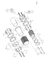
- the diagram 2 is the disjointed sketch of the generator
- the diagram 3 is the sectional view along the diagram 1's III-III.
- the hydrogen-oxygen mixed gas generator following the invention a round metal thin walled tube (10), multiple the 1 st electrolyte plates (31) with the 1 st small hole (31c) and the 1 st big hole (31b) each on the upper and lower part of the center hole (31a),multiple 2 nd electrolyte plates(31) with the small hole (32c) on the upper part of the center hole (32a) and the 2 nd big hole (32b) on the lower part of the center hole (32b), a number of rings with certain thickness (33) between the 1 st electrolyte plate(31) and the 2 nd electrolyte plate (32), electrolyte unit (30) including the 1 st electric pole (34) penetrating the 1 st small holes (31c) and the 2 nd electric pole (35) penetrating the 2 nd small holes (32c) as the 1 st electrolyte plate (31) and the 2 nd electrolyte plate (32) are place opposed to each
- Front sealing plate (46) is applied in middle of the front cover (10) and the thin walled tube (40) to seal between the front cover (40) and the thin walled tube (10) and the rear sealing plate is set up to seal the rear cover (50) and the thin walled tube (10).
- the front and rear sealing plates (46) (56) and the front and rear covers (40) (50) are likely to be made of insulating metal.
- the 1 st thermal conduction plate(70) is formed between the insulation pipe (20) and the thin walled tube (10) to deliver the heat produced while the electrolysis to the thin walled tube (10) through the insulation pipe (20) efficiently.
- the 2 nd thermal conduction plate (80) is formed between the heat radiant plate (60) and the thin walled tube (10) to transfer the heat from the thin walled tube (10) to the heat radiant plate (60).
- the thin walled tube (10) can be in any shape; circular, rectangular, hexagonal and so on. It can also be formed by metals such as stainless or alloy steel. In the invention explained above, the thin walled tube (10) is in a circular shape and has frontal and rear flanges (10a) (10b) on both sides. This thin walled tube (10) would be the body of the product.
- the insulation pipe (20) is favorably composed of materials in which the properties may not be altered during the electrolysis of water, such as Teflon rubber, acetal, or PP, PE substances.
- the 1 st big hole (31b) and the 1 st small hole (31c) are formed around the center hole (31a) at the center of the 1 st electrolyte plate (31).
- the cylindrical surface area inside the 1 st small hole (31c) touch the 1 st electric pole (34) but because the diameter of the 1 st big hole (31b) is larger than that of the 1 st small hole (31c), the inner surface are of the 1 st big hole (31b) does not touch the 1 st electric pole (34).
- the 2 nd big hole (32b) and the 2 nd small hole (32c) are formed around the center hole (32a) at the center of the 2 nd electrolyte plate (32).
- the center holes (31a)(32a) on the 1 st electrolyte plate (31) and the 2 nd electrolyte plate (32) are shaped as cylinders so water could flow by.
- the ring with a certain thickness (33) are the rings with the same diameter as the 1,2 nd electrolyte plates (31) (32) and separates the 1 st electrolyte plate (31) and the 2 nd electrolyte plate (32) so they would not touch each other.
- the 1,2 nd electrolyte plates (31) (32) and the ring with a certain thickness have width of 3mm.
- the 1,2 nd electric poles (34) (35) have bolts at the end of each pole.
- the 1 st and the 2 nd electrolyte plates (31)(32) are placed alternatively between the rings (33) and the 1 st electric pole (34) 9s connected to the 1 st electrolyte plate (31) electrically and the 2 nd electric pole (35) is connected to the 2 nd electrolyte plate(32).
- a terminal bolt (37) joining the cluster of bolts (34a)(35a) and the 1,2 nd electric poles (34)(35) can be installed.
- the terminal bolt (37) is pierced through the 1,2,3,4 th pipes (44)(45)(54)(55) and is composed of the bolt's (37a) which connects the 1,2 nd electric poles (34)(35) and the cluster of bolts (34a)(35a) and the bolt's head (37b) connected to the wire exposed outside the front and rear covers (40)(50) transferring electricity.
- the overall diameter is larger then the 1,2 nd electric poles (34)(35).
- the hydrogen-oxygen mixed gas generator in the example uses low voltage of DC 1-12 V but still dozens of amperes are used.
- the terminal wired to the 1,2 nd electric pole (34)(35) produce massive amount of heat.
- the 1,2 nd electric pole can manage some heat since they are under the water but the terminal above the water can damage the coating of the wires due to lots of heat.
- the terminal bolt (37) with larger diameter then the 1,2 nd electric poles is used.
- the terminal bolt's (37) body (37a) would radiate some heat by sinking into the water in the thin walled tube (10) decrease the heat produced due to the larger diameter of the bolt's head (37b) then that of the 1,2 nd electric poles (34)(35).
- the electrolyte plates (31) should be made from a material that can carry electrolysis effectively.
- One of the materials would be carbon nano-tube alloy steel.
- Carbon nano-tube alloy steel is formed when carbon nano-tube, nickel, and tourmaline powdered and compressed in a form of electrode plate and ignited. Sodium decarboxylation chemical composition may be added and the ignition is carried at 1300 °C.
- the electrolyte plates (31) can also be made from stainless steel which would carry out the electrolysis effectively and also separate the hydrogen-oxygen bubbles when polished by nano-technology the electrolyte plate (31) is made in metals such as stainless steel or alloy steels.
- Nano-technology mean polishing electrolyte plate's (31) surface by nano units. Polishing by nano technology would minimize the electrode plate's surface friction, making hydrogen or oxygen gas bubbles to separate easily.
- the technical, thermal, electrical, magnetic, and optical properties change when the size of the matter decreases from bulk to nano meter, making electrolysis on water effortless.
- tourmaline catalyst can be attached on the surface of electrolyte plate (31).
- the tourmaline catalyst would be grinded into micro to nanometer powder, burned in 1300 °C and glued to the electrolyte plate(31).
- Tourmaline is a mineral under the hexagonal system like crystal; electricity forms by friction, produce massive amount of anion, and catalyzes the electrolysis producing lots of hydrogen and oxygen.
- Tourmaline becomes a catalyst with many tiny pores that can increase the contact area with electrolyte after being powdered and burned.
- the tourmaline catalyst can promote the electrolysis of electrolytes when attached on the electrolyte plate (31).]
- the front cover (40) is joined with the frontal flange (10a) to insulate by the frontal sealing plate (46) in front of the thin walled tube (10), bolts (B) and nuts ().
- the rear cover (50) is joined with the rear flange (10b) to insulate by the rear sealing plate (56) at the back of the tube (10), bolts (B), and nuts (N).
- the front and rear water flowing pipes (41)(51) are set up opposite to the center holes (31a)(32a) on the 1,2 nd electrolyte plates (31)(32) so when water is flowing into the front or the rear water flowing pipe (41)(51), the water mixed with the hydrogen-oxygen mixed gas goes out to the other pipe.
- the front sealing plate (46) includes the front gasket (46a) between the front cover (40) and the front flange (10a) and the front gasket ring (46b) installed on the front of the front cover (40) and the back of the front flange (10a) by the bolts (B) and Nuts (N).
- the rear sealing plate (56) includes the rear gasket (56a) between the rear cover (50) and the rear flange (10b) and the rear gasket ring (56b) installed on the front of the rear cover (50) and the back of the rear flange (10b) by the bolts (B) and nuts (N).
- the insulating gaskets (47)(57) play insulators disconnecting electricity flowing from the 1,2 nd pipes (34)(35) and seals to prevent a leak as they are connected to the 1,2 nd pipes (44)(45) and the 3,4 th pipes (54)(55).
- the insulating gaskets (47)(57) contain the bodies of the gaskets (47a)(57a) on the 1,2,3,4 th pipes (44)(45)(54)(55) and gasket flanges (47b)(57b) which has bigger diameter than that of the gaskets (47a)(57a) on the outside of the front and rear covers (40)(50).
- the material can be insulating Teflon.
- the heat radiant plate (60) is composed of the heat radiant pipe (61) on the thin walled tube (10) in between the front and rear covers (40)(50) and the multiple heat radiant pins (62) placed apart from each other on the heat radiant pipe (61).
- the heat radiant pipe (61) and the pins (62) can be formed by polishing round aluminum or stainless pipes by NC machine, using casting, or sculpturing the heat resistant plastic or ceramics.
- the heat radiant pipe (61) and the pins (62) can be made separately and connected later on. Furthermore, to increase the heat resistance on the heat radiant plate (60), carbon nano-tube or tourmaline catalyst in nanometer size, preferably in 10-60 nanometers, can be applied alone or together.
- the 1 st thermal conduction plate transfers heat produced during the electrolysis to the thin walled tube (10) through the insulating pipe (20).
- the 2 nd thermal conduction plate delivers the heat transferred to the thin walled tube (10) to the heat radiant plate (60) efficiently.
- the 1,2 nd thermal conduction plates (70)(80) have carbon nano-tube and tourmaline catalysts, preferably in size of 10-6- nanometers, applied.
Landscapes
- Chemical & Material Sciences (AREA)
- Engineering & Computer Science (AREA)
- Metallurgy (AREA)
- Chemical Kinetics & Catalysis (AREA)
- Electrochemistry (AREA)
- Materials Engineering (AREA)
- Organic Chemistry (AREA)
- Inorganic Chemistry (AREA)
- Combustion & Propulsion (AREA)
- Mechanical Engineering (AREA)
- General Engineering & Computer Science (AREA)
- Electrolytic Production Of Non-Metals, Compounds, Apparatuses Therefor (AREA)
- Catalysts (AREA)
- Electrodes For Compound Or Non-Metal Manufacture (AREA)
- Oxygen, Ozone, And Oxides In General (AREA)
Abstract
This invention is about a hydrogen-oxygen generating apparatus which contains an insulation tube(20) inside the thin walled tube (10), multiple 1st electrolyte plate (31) that has the 1st small hole (31c) placed at the lower part of the center hole (31a) and the first big hole (31b) place on the upper part of the center hole (31a), multiple 2nd electrolyte plates(32) with the small hole (32c) on the upper part of the center hole (32a) and the 2nd big hole (32b) on the lower part of the center hole (32b), a number of rings with a certain thickness (33) between the 1st electrolyte plate (31) and the 2nd electrolytc plate(32), the electrolyte unit (30) including the 1st electric pole (34) penetrating the 1st small holes (31c) and the 2nd electric pole (35) penetrating the 2nd small holes (32c) as the 1st electrolyte plate (31) and the 2nd electrolyte plate (32) are place opposed to each other, the front cover (40) with the frontal water flowing pipe (41) at the center and the 1st electric pole (34) and the 2nd electric pole (35) piercing the cover through the 1,2nd pipes (44)(45) up and down the cover in front of the thin walled tube (10), the rear cover (50) with the 1st electric pole (34) and 2nd electric pole (35) piecing through the 3,4th pipes (54)(55) at the upper and lower part of the rear water flowing pipe (51) at the center of the rear cover (50) at the back of the thin walled tube (10), and insulating gaskets (47)(57) on the 1,2nd electric pole (34)(35) connecting the 1,2nd pipes (44)(45) and the 3,4rh pipes (54)(55).
Description
- The present invention is about a hydrogen-oxygen generator that can produce hydrogen-oxygen mixture effectively from water.
- Hydrogen-oxygen mixed-gas generating system is made to produce hydrogen and oxygen from electrolyzed water; to gain hydrogen-oxygen mixed gas, water containing small amount of electrolytes is provided to the storage with positive (+) and negative (-) electrodes and electrolyzed by direct current. Hydrogen and oxygen produced from the process is at ratio of 2 : 1 and hydrogen is formed as bubbles on the surface of negative (-) electrode and oxygen in bubbles on the positive (+) electrode. The hydrogen and oxygen produced can be mixed and combusted. Also hydrogen- oxygen gas mixture does not produce any pollutants when ignited, making it an important eco-friendly energy source
- However, because the amount of hydrogen-oxygen produced is relatively small compared to the amount of electric current transferred to (-) and (+) electrodes, additional gas, such as propane gas, is added and combusted, resulting in low economical efficiency.
- The invention is created to solve the above mentioned problem; to provide economical hydrogen-oxygen mixed gas generator by expanding the produced amount of hydrogen-oxygen gas mixture compared to the amount of electricity used.
-
- Diagram 1 is a sketch of hydrogen-oxygen mixed gas generator;
- Diagram 2 is a sketch of dissembled hydrogen-oxygen mixed gas generator;
- Diagram 3 is a sectional sketch along the diagram 1's III-III'.
- The hydrogen-oxygen generator produced to solve the above problem contains a caliber, a metal thin walled tube (10), an insulation tube(20) inside the thin walled tube (10), multiple 1st electrolyte plate (31) that has the 1st small hole (31c) placed at the lower part of the center hole (31a) and the first big hole (31b) place on the upper part of the center hole (31a), multiple 2nd electrolyte plates(32) with the small hole (32c) on the upper part of the center hole (32a) and the 2nd big hole (32b) on the lower part of the center hole (32b), a number of rings with a certain thickness (33) between the 1st electrolyte plate (31) and the 2nd electrolyte plate(32), the electrolyte unit (30) including the 1st electric pole (34) penetrating the 1st small holes (31c) and the 2nd electric pole (35) penetrating the 2nd small holes (32c) as the 1st electrolyte plate (31) and the 2nd electrolyte plate (32) are place opposed to each other, the front cover (40) with the frontal water flowing pipe (41) at the center and the 1st electric pole (34) and the 2nd electric pole (35) piercing the cover through the 1,2nd pipes (44)(45) up and down the cover in front of the thin walled tube (10), the rear cover (50) with the 1st electric pole (34) and 2nd electric pole (35) piecing through the 3,4th pipes (54)(55) at the upper and lower part of the rear water flowing pipe (51) at the center of the rear cover (50) at the back of the thin walled tube (10), insulating gaskets (47)(57) on the 1,2nd electric pole (34)(35) connecting the 1,2nd pipes (44)(45) and the 3,4rh pipes (54)(55), and the heat radiant plate (60) containing a number of heat radiant pins (62).
- According to the developed hydrogen-oxygen mixed gas generator the amount of hydrogen-oxygen mixed gas produced can be increased relative to the amount of electricity used and economical efficiency for the gas can be combusted without adding any additional gas, such as propane gas.
Also, hydrogen and oxygen are formed in bubble forms can be easily removed from the electrodes. As a result, the surface area of the electrodes is enlarged, amplifying the electrolysis efficiency. - The following explanations are based on the diagrams attached.
- Diagram 1 is the whole sketch of the hydrogen-oxygen generator, the diagram 2 is the disjointed sketch of the generator, and the diagram 3 is the sectional view along the diagram 1's III-III.
- As drawn, the hydrogen-oxygen mixed gas generator following the invention a round metal thin walled tube (10), multiple the 1st electrolyte plates (31) with the 1st small hole (31c) and the 1st big hole (31b) each on the upper and lower part of the center hole (31a),multiple 2nd electrolyte plates(31) with the small hole (32c) on the upper part of the center hole (32a) and the 2nd big hole (32b) on the lower part of the center hole (32b), a number of rings with certain thickness (33) between the 1st electrolyte plate(31) and the 2nd electrolyte plate (32), electrolyte unit (30) including the 1st electric pole (34) penetrating the 1st small holes (31c) and the 2nd electric pole (35) penetrating the 2nd small holes (32c) as the 1st electrolyte plate (31) and the 2nd electrolyte plate (32) are place opposed to each other, the front cover (40) with the frontal water flowing pipe (41) at the center and the 1st electric pole (34) and the 2nd electric pole (35) piercing the cover through the 1,2nd pipes (44)(45) up and down the cover in front of the thin walled tube (10), the rear cover (50) with the 1st electric pole (34) and 2nd electric pole (35) piecing through the 3,4th pipes (54)(55) at the upper and lower part of the rear water flowing pipe (51) at the center of the rear cover (50) at the back of the thin walled tube (10), insulating gaskets (47)(57) on the 1,2nd electric pole (34)(35) connecting the 1,2nd pipes (44)(45) and the 3,4rh pipes (54)(55), and the heat radiant plate (60) containing a number of heat radiant pins (62).
- Front sealing plate (46) is applied in middle of the front cover (10) and the thin walled tube (40) to seal between the front cover (40) and the thin walled tube (10) and the rear sealing plate is set up to seal the rear cover (50) and the thin walled tube (10). The front and rear sealing plates (46) (56) and the front and rear covers (40) (50) are likely to be made of insulating metal.
- The 1st thermal conduction plate(70) is formed between the insulation pipe (20) and the thin walled tube (10) to deliver the heat produced while the electrolysis to the thin walled tube (10) through the insulation pipe (20) efficiently. Also the 2nd thermal conduction plate (80) is formed between the heat radiant plate (60) and the thin walled tube (10) to transfer the heat from the thin walled tube (10) to the heat radiant plate (60). The thin walled tube (10) can be in any shape; circular, rectangular, hexagonal and so on. It can also be formed by metals such as stainless or alloy steel. In the invention explained above, the thin walled tube (10) is in a circular shape and has frontal and rear flanges (10a) (10b) on both sides. This thin walled tube (10) would be the body of the product.
- The insulation pipe (20), adhered inside the thin walled tube (10), insulates the insulation pipe (20) and the electrolyte plate (30). The insulation pipe (20) is favorably composed of materials in which the properties may not be altered during the electrolysis of water, such as Teflon rubber, acetal, or PP, PE substances.
- As drawn, the 1st big hole (31b) and the 1st small hole (31c) are formed around the center hole (31a) at the center of the 1st electrolyte plate (31). At this point, the cylindrical surface area inside the 1st small hole (31c) touch the 1st electric pole (34) but because the diameter of the 1st big hole (31b) is larger than that of the 1st small hole (31c), the inner surface are of the 1st big hole (31b) does not touch the 1st electric pole (34). Also, the 2nd big hole (32b) and the 2nd small hole (32c) are formed around the center hole (32a) at the center of the 2nd electrolyte plate (32). At this point, the cylindrical surface area inside the 2nd small hole (32c) touch the 2nd electric pole (35) but because the diameter of the 2nd big hole (32b) is larger than that of the 2nd small hole (32c), the inner surface are of the 2nd big hole (32b) does not touch the 2nd electric pole (35). The center holes (31a)(32a) on the 1st electrolyte plate (31) and the 2nd electrolyte plate (32) are shaped as cylinders so water could flow by.
- The ring with a certain thickness (33) are the rings with the same diameter as the 1,2nd electrolyte plates (31) (32) and separates the 1st electrolyte plate (31) and the 2nd electrolyte plate (32) so they would not touch each other. In the example, the 1,2nd electrolyte plates (31) (32) and the ring with a certain thickness have width of 3mm.
- The 1,2nd electric poles (34) (35) have bolts at the end of each pole.
- According to the structure described, the 1st and the 2nd electrolyte plates (31)(32) are placed alternatively between the rings (33) and the 1st electric pole (34) 9s connected to the 1st electrolyte plate (31) electrically and the 2nd electric pole (35) is connected to the 2nd electrolyte plate(32).
- On the 1, 2nd pipes (44)(45) of the front cover (40) and the 3,4th pipes (54)(55) on the rear cover (50), a terminal bolt (37) joining the cluster of bolts (34a)(35a) and the 1,2nd electric poles (34)(35) can be installed. The terminal bolt (37) is pierced through the 1,2,3,4th pipes (44)(45)(54)(55) and is composed of the bolt's (37a) which connects the 1,2nd electric poles (34)(35) and the cluster of bolts (34a)(35a) and the bolt's head (37b) connected to the wire exposed outside the front and rear covers (40)(50) transferring electricity. The overall diameter is larger then the 1,2nd electric poles (34)(35).
- The hydrogen-oxygen mixed gas generator in the example uses low voltage of DC 1-12 V but still dozens of amperes are used. As a result, the terminal wired to the 1,2nd electric pole (34)(35) produce massive amount of heat. The 1,2nd electric pole can manage some heat since they are under the water but the terminal above the water can damage the coating of the wires due to lots of heat. To prevent it, the terminal bolt (37) with larger diameter then the 1,2nd electric poles is used. The terminal bolt's (37) body (37a) would radiate some heat by sinking into the water in the thin walled tube (10) decrease the heat produced due to the larger diameter of the bolt's head (37b) then that of the 1,2nd electric poles (34)(35).
- The electrolyte plates (31) should be made from a material that can carry electrolysis effectively. One of the materials would be carbon nano-tube alloy steel. Carbon nano-tube alloy steel is formed when carbon nano-tube, nickel, and tourmaline powdered and compressed in a form of electrode plate and ignited. Sodium decarboxylation chemical composition may be added and the ignition is carried at 1300 °C.
- The electrolyte plates (31) can also be made from stainless steel which would carry out the electrolysis effectively and also separate the hydrogen-oxygen bubbles when polished by nano-technology the electrolyte plate (31) is made in metals such as stainless steel or alloy steels.
- Nano-technology mean polishing electrolyte plate's (31) surface by nano units. Polishing by nano technology would minimize the electrode plate's surface friction, making hydrogen or oxygen gas bubbles to separate easily. The technical, thermal, electrical, magnetic, and optical properties change when the size of the matter decreases from bulk to nano meter, making electrolysis on water effortless.
- On the surface of electrolyte plate (31), tourmaline catalyst can be attached. The tourmaline catalyst would be grinded into micro to nanometer powder, burned in 1300 °C and glued to the electrolyte plate(31). Tourmaline is a mineral under the hexagonal system like crystal; electricity forms by friction, produce massive amount of anion, and catalyzes the electrolysis producing lots of hydrogen and oxygen. Tourmaline becomes a catalyst with many tiny pores that can increase the contact area with electrolyte after being powdered and burned. The tourmaline catalyst can promote the electrolysis of electrolytes when attached on the electrolyte plate (31).]
- The front cover (40) is joined with the frontal flange (10a) to insulate by the frontal sealing plate (46) in front of the thin walled tube (10), bolts (B) and nuts (). Also, the rear cover (50) is joined with the rear flange (10b) to insulate by the rear sealing plate (56) at the back of the tube (10), bolts (B), and nuts (N). The front and rear water flowing pipes (41)(51) are set up opposite to the center holes (31a)(32a) on the 1,2nd electrolyte plates (31)(32) so when water is flowing into the front or the rear water flowing pipe (41)(51), the water mixed with the hydrogen-oxygen mixed gas goes out to the other pipe.
- As drawn in the diagram 2 and 3, the front sealing plate (46) includes the front gasket (46a) between the front cover (40) and the front flange (10a) and the front gasket ring (46b) installed on the front of the front cover (40) and the back of the front flange (10a) by the bolts (B) and Nuts (N).
- As drawn in the diagram 2 and 3, the rear sealing plate (56) includes the rear gasket (56a) between the rear cover (50) and the rear flange (10b) and the rear gasket ring (56b) installed on the front of the rear cover (50) and the back of the rear flange (10b) by the bolts (B) and nuts (N).
The insulating gaskets (47)(57) play insulators disconnecting electricity flowing from the 1,2nd pipes (34)(35) and seals to prevent a leak as they are connected to the 1,2nd pipes (44)(45) and the 3,4th pipes (54)(55). The insulating gaskets (47)(57) contain the bodies of the gaskets (47a)(57a) on the 1,2,3,4th pipes (44)(45)(54)(55) and gasket flanges (47b)(57b) which has bigger diameter than that of the gaskets (47a)(57a) on the outside of the front and rear covers (40)(50). The material can be insulating Teflon. - The heat radiant plate (60) is composed of the heat radiant pipe (61) on the thin walled tube (10) in between the front and rear covers (40)(50) and the multiple heat radiant pins (62) placed apart from each other on the heat radiant pipe (61). The heat radiant pipe (61) and the pins (62) can be formed by polishing round aluminum or stainless pipes by NC machine, using casting, or sculpturing the heat resistant plastic or ceramics.
- But in forming the heat radiant plate (60), the heat radiant pipe (61) and the pins (62) can be made separately and connected later on. Furthermore, to increase the heat resistance on the heat radiant plate (60), carbon nano-tube or tourmaline catalyst in nanometer size, preferably in 10-60 nanometers, can be applied alone or together.
- The 1st thermal conduction plate transfers heat produced during the electrolysis to the thin walled tube (10) through the insulating pipe (20). The 2nd thermal conduction plate delivers the heat transferred to the thin walled tube (10) to the heat radiant plate (60) efficiently. To accomplish the goals, the 1,2nd thermal conduction plates (70)(80) have carbon nano-tube and tourmaline catalysts, preferably in size of 10-6- nanometers, applied.
- According to the structure described, if electric current is provided to the 1,2nd electric poles (35)(45) when water is flowing in either front or rear water flowing pipes (41)(51), - and + electric charge is formed on the surfaces of the 1,2nd electrolyte plates (31)(32), and the magnetic field is created between the 1,2nd electrolyte plates (31)(32). The electric space, where electrolysis is carried, becomes the place where magnetic field is formed and the total electric space expands according to the number of the 1,2nd electrolyte plates (31)(32) so the electrolysis becomes active, producing lots of hydrogen and oxygen gas. The hydrogen-oxygen gas produced goes out through one of the front or the rear water flowing pipes after mixed together.
- The invention is explained based on the example experimented but keep in mind that this is only one of the possibilities and anyone with sufficient knowledge in the field would understand that variations can be applied.
-
- 10
- - thin walled tube
- 10a, 10b
- - front and rear flange
- 20
- - insulation pipe
- 30
- - electrolyte unit
- 31
- - the 1st electrolyte plate
- 31a
- - center hole
- 31b
- - the 1st big hole
- 31c
- - the 1st small hole
- 32
- - the 2nd electrolyte plate
- 32a
- - center hole
- 32b
- - the 2nd big hole
- 32c
- - the 2nd small hole
- 33
- - ring with a certain thickness
- 34,35
- - the 1,2nd electric poles
- 34a,35a
- - cluster of bolts
- 37
- - terminal bolts
- 37a
- - bolt's body
- 37b
- - bolt's head
- 40
- - front cover
- 41
- - front water flowing pipe
- 44,45
- - the 1,2nd pipe
- 46
- - front sealing plate
- 46a
- - front gasket
- 46b
- - front gasket ring
- 56
- - rear sealing plate
- 56a
- - rear gasket
- 56b
- - rear gasket ring
- 47,57
- - insulation gasket
- 47a,47b
- - body of gasket
- 57a,57b
- - gasket flange
- 50
- - rear cover
- 51
- - rear water flowing pipe
- 54,55
- - the 3,4th pipes
- 60
- - heat radiant plate
- 61
- - heat radiant pipe
- 62
- - heat radiant pin
- 70
- - the 1st thermal conduction plate
- 80
- - the 2nd thermal conduction plate
Claims (6)
1. A hydrogen-oxygen generating apparatus comprising a metal thin walled tube (10);
an insulation tube(20) inside the thin walled tube (10);
the multiple 1st electrolyte plate (31) that has the 1st small hole (31c) placed at the lower part of the center hole (31a) and the first big hole (31b) place on the upper part of the center hole (31a), multiple 2nd electrolyte plates(32) with the small hole (32c) on the upper part of the center hole (32a) and the 2nd big hole (32b) on the lower part of the center hole (32b), a number of rings with a certain thickness (33) between the 1st electrolyte plate (31) and the 2nd electrolyte plate(32), the electrolyte unit (30) including the 1st electric pole (34) penetrating the 1st small holes (31c) and the 2nd electric pole (35) penetrating the 2nd small holes (32c) as the 1st electrolyte plate (31) and the 2nd electrolyte plate (32) are place opposed to each other;
the front cover (40) with the frontal water flowing pipe (41) at the center and the 1st electric pole (34) and the 2nd electric pole (35) piercing the cover through the 1,2nd pipes (44)(45) up and down the cover in front of the thin walled tube (10);
the rear cover (50) with the 1st electric pole (34) and 2nd electric pole (35) piecing through the 3,4th pipes (54)(55) at the upper and lower part of the rear water flowing pipe (51) at the center of the rear cover (50) at the back of the thin walled tube (10);
the insulating gaskets (47)(57) on the 1,2nd electric pole (34)(35) connecting the 1,2nd pipes (44)(45) and the 3,4rh pipes (54)(55);
and the heat radiant plate (60) containing a number of heat radiant pins (62).
an insulation tube(20) inside the thin walled tube (10);
the multiple 1st electrolyte plate (31) that has the 1st small hole (31c) placed at the lower part of the center hole (31a) and the first big hole (31b) place on the upper part of the center hole (31a), multiple 2nd electrolyte plates(32) with the small hole (32c) on the upper part of the center hole (32a) and the 2nd big hole (32b) on the lower part of the center hole (32b), a number of rings with a certain thickness (33) between the 1st electrolyte plate (31) and the 2nd electrolyte plate(32), the electrolyte unit (30) including the 1st electric pole (34) penetrating the 1st small holes (31c) and the 2nd electric pole (35) penetrating the 2nd small holes (32c) as the 1st electrolyte plate (31) and the 2nd electrolyte plate (32) are place opposed to each other;
the front cover (40) with the frontal water flowing pipe (41) at the center and the 1st electric pole (34) and the 2nd electric pole (35) piercing the cover through the 1,2nd pipes (44)(45) up and down the cover in front of the thin walled tube (10);
the rear cover (50) with the 1st electric pole (34) and 2nd electric pole (35) piecing through the 3,4th pipes (54)(55) at the upper and lower part of the rear water flowing pipe (51) at the center of the rear cover (50) at the back of the thin walled tube (10);
the insulating gaskets (47)(57) on the 1,2nd electric pole (34)(35) connecting the 1,2nd pipes (44)(45) and the 3,4rh pipes (54)(55);
and the heat radiant plate (60) containing a number of heat radiant pins (62).
2. A hydrogen-oxygen generating apparatus according to claim 1, further comprising a front sealing plate (46) applied in middle of the front cover (40) and the thin walled tube (10) to seal between the front cover (40) and the thin walled tube (10);
and the rear sealing plate applied in middle of the rear cover(50) and the thin walled tube(10) to seal the rear cover (50) and the thin walled tube (10).
and the rear sealing plate applied in middle of the rear cover(50) and the thin walled tube(10) to seal the rear cover (50) and the thin walled tube (10).
3. A hydrogen-oxygen generating apparatus according to claim 2, wherein the front sealing plate (46) includes the front gasket (46a) between the front cover (40) and the front flange (10a) and the front gasket ring (46b) installed on the front of the front cover (40) and the back of the front flange (10a) by the bolts (B) and Nuts (N); and
the rear sealing plate (56) includes the rear gasket (56a) between the rear cover (50) and the rear flange (10b) and the rear gasket ring (56b) installed on the front of the rear cover (50) and the back of the rear flange (10b) by the bolts (B) and nuts (N).
the rear sealing plate (56) includes the rear gasket (56a) between the rear cover (50) and the rear flange (10b) and the rear gasket ring (56b) installed on the front of the rear cover (50) and the back of the rear flange (10b) by the bolts (B) and nuts (N).
4. A hydrogen-oxygen generating apparatus according to claim 1, in which the electrolyte plates (31) is made from carbon nano-tube alloy steel.
5. A hydrogen-oxygen generating apparatus according to claim 1, the surface of the electrolyte plates (31) is polished by nano-technology to carry out the electrolysis effectively and also to separate the hydrogen-oxygen bubbles.
6. A hydrogen-oxygen generating apparatus according to claim 1, on the surface of electrolyte plate (31), tourmaline catalyst is attached.
Applications Claiming Priority (1)
| Application Number | Priority Date | Filing Date | Title |
|---|---|---|---|
| KR1020080121190A KR100894288B1 (en) | 2008-12-02 | 2008-12-02 | Hydrogen-oxygen mixed gas generator |
Publications (1)
| Publication Number | Publication Date |
|---|---|
| EP2199431A1 true EP2199431A1 (en) | 2010-06-23 |
Family
ID=40757998
Family Applications (1)
| Application Number | Title | Priority Date | Filing Date |
|---|---|---|---|
| EP09275119A Withdrawn EP2199431A1 (en) | 2008-12-02 | 2009-12-01 | A hydrogen-oxygen generating apparatus |
Country Status (8)
| Country | Link |
|---|---|
| US (1) | US20100155234A1 (en) |
| EP (1) | EP2199431A1 (en) |
| JP (1) | JP2010133026A (en) |
| KR (1) | KR100894288B1 (en) |
| CN (1) | CN101748421A (en) |
| AU (1) | AU2009243469A1 (en) |
| BR (1) | BRPI0905352A2 (en) |
| TW (1) | TW201030186A (en) |
Cited By (2)
| Publication number | Priority date | Publication date | Assignee | Title |
|---|---|---|---|---|
| WO2012151188A2 (en) | 2011-05-03 | 2012-11-08 | Hydroripp Llc | Hydrogen gas generator |
| US9939866B2 (en) | 2014-05-22 | 2018-04-10 | Uripp Llc | Operating system control for power source |
Families Citing this family (5)
| Publication number | Priority date | Publication date | Assignee | Title |
|---|---|---|---|---|
| KR100930790B1 (en) * | 2009-02-18 | 2009-12-09 | 황부성 | Hydrogen generation electrode plate and manufacturing method for manufacturing same |
| WO2012144961A1 (en) * | 2011-04-21 | 2012-10-26 | Katanyoophatai Co., Ltd. | Catalytic converter for hydrogen powered engine |
| CN109312478B (en) * | 2016-06-07 | 2020-10-16 | 富士胶片株式会社 | Photocatalyst electrode, artificial photosynthesis module and artificial photosynthesis device |
| CN106090910B (en) * | 2016-08-15 | 2017-11-24 | 衢州昀睿工业设计有限公司 | A kind of aqueous medium gasification combustion system |
| CN109869717B (en) * | 2019-01-29 | 2020-05-19 | 武汉船用电力推进装置研究所(中国船舶重工集团公司第七一二研究所) | Self-heating hydrogen-oxygen catalytic combustor and self-heating starting method |
Citations (5)
| Publication number | Priority date | Publication date | Assignee | Title |
|---|---|---|---|---|
| WO1993025730A1 (en) * | 1992-06-17 | 1993-12-23 | Baker Hughes Incorporated | Electrolytic cell |
| WO2002033769A2 (en) * | 2000-10-17 | 2002-04-25 | Ho-Tong, Robert, Kenneth | Method of and an apparatus for supplying fuel to a vehicle |
| KR20040051155A (en) * | 2002-12-12 | 2004-06-18 | 한국정수공업 주식회사 | Method to making the carbon electrode |
| JP2005240152A (en) * | 2004-02-27 | 2005-09-08 | Jippu:Kk | Method and device for electrolyzing water |
| WO2006105648A1 (en) * | 2005-04-05 | 2006-10-12 | Cropley Holdings Ltd. | Household appliances which utilize an electrolyzer and electrolyzer that may be used therein |
Family Cites Families (14)
| Publication number | Priority date | Publication date | Assignee | Title |
|---|---|---|---|---|
| DE2442474A1 (en) * | 1974-09-05 | 1976-03-18 | Sachs Systemtechnik Gmbh | MULTIPLE-PLATE CELL FOR DISINFECTION AND DETOXIFICATION OF LIQUIDS USING ANODIC OXYDATION |
| US5244558A (en) * | 1992-09-24 | 1993-09-14 | Chiang Huang C | Apparatus for generating a mixture of hydrogen and oxygen for producing a hot flame |
| JP2911381B2 (en) * | 1995-03-01 | 1999-06-23 | 神鋼パンテツク株式会社 | Hydrogen / oxygen generator |
| AU5412498A (en) * | 1997-12-15 | 1999-07-05 | World Fusion Limited | Water-decomposition gas generating device |
| KR100405163B1 (en) | 2001-05-08 | 2003-11-12 | 키펙스솔루션스 주식회사 | Electrolyser |
| JP2003313689A (en) | 2002-04-22 | 2003-11-06 | Shinko Pantec Co Ltd | Hydrogen oxygen generator |
| US20030205482A1 (en) * | 2002-05-02 | 2003-11-06 | Allen Larry D. | Method and apparatus for generating hydrogen and oxygen |
| US7588074B1 (en) * | 2004-12-21 | 2009-09-15 | Robert Alvin White | In the rate of energy transfer across boundaries |
| JP4074322B2 (en) * | 2006-07-06 | 2008-04-09 | 炳霖 ▲楊▼ | Combustion gas generator using electrolysis and in-vehicle combustion gas generator |
| TWI439568B (en) * | 2006-11-20 | 2014-06-01 | Univ California | Gated electrodes for electrolysis and electrosynthesis |
| KR100867896B1 (en) * | 2007-01-18 | 2008-11-10 | 주식회사 우리기술 | Robot cleaning building exterior walls and windows. |
| KR100816098B1 (en) * | 2007-01-26 | 2008-03-25 | 농업회사법인 주식회사 파워그린 | Electrolyzer of Water Gas Generator |
| JP3142740U (en) * | 2008-03-24 | 2008-06-26 | 博 加納 | An electrolysis tank made of hard vinyl chloride, which has a structure in which the electrolysis tank itself is an insulating material, grooves on both left and right wall surfaces of the electrolysis tank are equally spaced, and electrode plates can be arranged. |
| KR100862924B1 (en) * | 2008-07-14 | 2008-10-13 | 황부성 | Hydrogen-oxygen mixed gas generator |
-
2008
- 2008-12-02 KR KR1020080121190A patent/KR100894288B1/en not_active Expired - Fee Related
-
2009
- 2009-11-30 US US12/592,637 patent/US20100155234A1/en not_active Abandoned
- 2009-12-01 EP EP09275119A patent/EP2199431A1/en not_active Withdrawn
- 2009-12-01 AU AU2009243469A patent/AU2009243469A1/en not_active Abandoned
- 2009-12-01 BR BRPI0905352A patent/BRPI0905352A2/en not_active Application Discontinuation
- 2009-12-02 CN CN200910205999A patent/CN101748421A/en active Pending
- 2009-12-02 JP JP2009274604A patent/JP2010133026A/en active Pending
- 2009-12-02 TW TW098141199A patent/TW201030186A/en unknown
Patent Citations (5)
| Publication number | Priority date | Publication date | Assignee | Title |
|---|---|---|---|---|
| WO1993025730A1 (en) * | 1992-06-17 | 1993-12-23 | Baker Hughes Incorporated | Electrolytic cell |
| WO2002033769A2 (en) * | 2000-10-17 | 2002-04-25 | Ho-Tong, Robert, Kenneth | Method of and an apparatus for supplying fuel to a vehicle |
| KR20040051155A (en) * | 2002-12-12 | 2004-06-18 | 한국정수공업 주식회사 | Method to making the carbon electrode |
| JP2005240152A (en) * | 2004-02-27 | 2005-09-08 | Jippu:Kk | Method and device for electrolyzing water |
| WO2006105648A1 (en) * | 2005-04-05 | 2006-10-12 | Cropley Holdings Ltd. | Household appliances which utilize an electrolyzer and electrolyzer that may be used therein |
Non-Patent Citations (1)
| Title |
|---|
| DATABASE WPI Week 200565, Derwent World Patents Index; AN 2005-633213, XP002562791 * |
Cited By (5)
| Publication number | Priority date | Publication date | Assignee | Title |
|---|---|---|---|---|
| WO2012151188A2 (en) | 2011-05-03 | 2012-11-08 | Hydroripp Llc | Hydrogen gas generator |
| EP2705173A4 (en) * | 2011-05-03 | 2014-12-24 | Hydroripp Llc | HYDROGEN GAS GENERATOR |
| US9217203B2 (en) | 2011-05-03 | 2015-12-22 | Scott Gotheil-Yelle | Hydrogen gas generator |
| RU2616613C2 (en) * | 2011-05-03 | 2017-04-18 | ХАЙДРОРИПП ЭлЭлСи | Hydrogen gas generator |
| US9939866B2 (en) | 2014-05-22 | 2018-04-10 | Uripp Llc | Operating system control for power source |
Also Published As
| Publication number | Publication date |
|---|---|
| TW201030186A (en) | 2010-08-16 |
| US20100155234A1 (en) | 2010-06-24 |
| BRPI0905352A2 (en) | 2015-10-27 |
| KR100894288B1 (en) | 2009-04-21 |
| JP2010133026A (en) | 2010-06-17 |
| CN101748421A (en) | 2010-06-23 |
| AU2009243469A1 (en) | 2010-06-17 |
Similar Documents
| Publication | Publication Date | Title |
|---|---|---|
| EP2199431A1 (en) | A hydrogen-oxygen generating apparatus | |
| US9157159B2 (en) | System and method for generating hydrogen and oxygen gases | |
| US6890410B2 (en) | Apparatus for converting a fluid into at least two gasses through electrolysis | |
| US20100116648A1 (en) | Hydrogen-oxygen mixed gas generator | |
| CN102395710B (en) | Electrolytic cell and method of use thereof | |
| CN102396093B (en) | For controlling the apparatus and method of nucleation in electrolytic process | |
| CN101838815A (en) | Hydrogen-oxygen generating apparatus | |
| US20180371627A1 (en) | Electrolysis device | |
| CN100595334C (en) | Integrated series-parallel combined electrolyzer | |
| KR100884763B1 (en) | Hydrogen-oxygen mixed gas generator | |
| KR100862924B1 (en) | Hydrogen-oxygen mixed gas generator | |
| AU2012202480A1 (en) | A hydrogen-oxygen generation apparatus | |
| Wu et al. | Macroporous spider net-like NiO nanowire on carbon nanowire to grow a biofilm with multi-layered bacterium cells toward high-power microbial fuel cells | |
| AU2012202424A1 (en) | Hydrogen-oxygen mixed gas generator | |
| Xiao et al. | Combined nano/micro-structure of Ni12P5-Ni2P nanorod array for effective wide pH range HER and overall alkaline water-splitting | |
| CN212278527U (en) | Testing structure for arc plasma | |
| Rahmadina et al. | The Comparison of Hydrogen Purity on Brown’s Gas Using Dry Cell Electrolyzer with/without Polyvinyl Alcohol (PVA) Separator Membrane | |
| US8535493B2 (en) | “Miami Max Hydro” the ultimate hydrogen cell | |
| Ooi et al. | Study on ball milling duration effect of n-doped graphene for PEMFC application | |
| KR101029652B1 (en) | Brown Gas Generator | |
| CA2996851C (en) | System and method for generating hydrogen and oxygen gases | |
| PL225119B1 (en) | Hydrogen and oxygen generator |
Legal Events
| Date | Code | Title | Description |
|---|---|---|---|
| PUAI | Public reference made under article 153(3) epc to a published international application that has entered the european phase |
Free format text: ORIGINAL CODE: 0009012 |
|
| AK | Designated contracting states |
Kind code of ref document: A1 Designated state(s): AT BE BG CH CY CZ DE DK EE ES FI FR GB GR HR HU IE IS IT LI LT LU LV MC MK MT NL NO PL PT RO SE SI SK SM TR |
|
| AX | Request for extension of the european patent |
Extension state: AL BA RS |
|
| 17P | Request for examination filed |
Effective date: 20101231 |
|
| 17Q | First examination report despatched |
Effective date: 20110309 |
|
| STAA | Information on the status of an ep patent application or granted ep patent |
Free format text: STATUS: THE APPLICATION IS DEEMED TO BE WITHDRAWN |
|
| 18D | Application deemed to be withdrawn |
Effective date: 20130702 |