EP2199205A2 - Resonance reduction device for ram air turbine - Google Patents
Resonance reduction device for ram air turbine Download PDFInfo
- Publication number
- EP2199205A2 EP2199205A2 EP09252865A EP09252865A EP2199205A2 EP 2199205 A2 EP2199205 A2 EP 2199205A2 EP 09252865 A EP09252865 A EP 09252865A EP 09252865 A EP09252865 A EP 09252865A EP 2199205 A2 EP2199205 A2 EP 2199205A2
- Authority
- EP
- European Patent Office
- Prior art keywords
- mass
- assembly
- ram air
- air turbine
- recited
- Prior art date
- Legal status (The legal status is an assumption and is not a legal conclusion. Google has not performed a legal analysis and makes no representation as to the accuracy of the status listed.)
- Granted
Links
- 230000033001 locomotion Effects 0.000 claims description 11
- 230000000694 effects Effects 0.000 description 2
- 238000012986 modification Methods 0.000 description 2
- 230000004048 modification Effects 0.000 description 2
- 230000000712 assembly Effects 0.000 description 1
- 238000000429 assembly Methods 0.000 description 1
- 230000009347 mechanical transmission Effects 0.000 description 1
- 238000000034 method Methods 0.000 description 1
- 238000010248 power generation Methods 0.000 description 1
Images


Classifications
-
- B—PERFORMING OPERATIONS; TRANSPORTING
- B64—AIRCRAFT; AVIATION; COSMONAUTICS
- B64D—EQUIPMENT FOR FITTING IN OR TO AIRCRAFT; FLIGHT SUITS; PARACHUTES; ARRANGEMENTS OR MOUNTING OF POWER PLANTS OR PROPULSION TRANSMISSIONS IN AIRCRAFT
- B64D41/00—Power installations for auxiliary purposes
- B64D41/007—Ram air turbines
-
- Y—GENERAL TAGGING OF NEW TECHNOLOGICAL DEVELOPMENTS; GENERAL TAGGING OF CROSS-SECTIONAL TECHNOLOGIES SPANNING OVER SEVERAL SECTIONS OF THE IPC; TECHNICAL SUBJECTS COVERED BY FORMER USPC CROSS-REFERENCE ART COLLECTIONS [XRACs] AND DIGESTS
- Y02—TECHNOLOGIES OR APPLICATIONS FOR MITIGATION OR ADAPTATION AGAINST CLIMATE CHANGE
- Y02T—CLIMATE CHANGE MITIGATION TECHNOLOGIES RELATED TO TRANSPORTATION
- Y02T50/00—Aeronautics or air transport
- Y02T50/40—Weight reduction
Definitions
- This disclosure generally relates to ram air turbine assemblies. More particularly, this disclosure relates to a method and device for reducing structural resonances of a ram air turbine assembly.
- a ram air turbine is utilized in aircraft as a backup power generator. Upon failure of the primary power generator, the ram air turbine is deployed. Deployment entails movement from a position within the aircraft to an extended position where the turbine blades are exposed to ram air outside of the aircraft. The turbine blades rotate a generator to provide electrical power, a pump to provide hydraulic power or both at the same time to aircraft systems in the absence of primary electrical and hydraulic power.
- the ram air turbine is a back-up device and therefore is rarely used. However, although rarely used, it is important that the ram air turbine operate efficiently and properly when deployed.
- Conventional ram air turbines can encounter self-induced vibrations caused by imbalance of the turbine. The turbine imbalance is primarily caused by motion of the governor components and governor springs. The self-induced vibrations are amplified when there is a structural resonance within the operating speed range of the turbine. The vibration can degrade performance and therefore it is desirable to modify the structural resonance frequency so the ram air turbine is less susceptible to vibration.
- An example ram air turbine assembly includes a preferentially located mass that modifies or reduces the magnitude of the resonance frequency to desired levels.
- the example mass can be fixed in a specific location on the ram air turbine or can be extended as the ram air turbine is moved to a deployed operating position.
- the preferential location of a mass modifies the structural frequency of the ram air turbine structure to reduce undesired vibrations that can occur during operation.
- the example masses can be movable to reduce the space required for storage of the ram air turbine.
- the preferential location of a mass at specific locations on the ram air turbine can reduce resonance amplitude or otherwise modify structural resonance frequencies, thereby reducing the need to increase structural features of the overall ram air turbine assembly.
- a ram air turbine assembly 10 includes a deployable support structure 14 pivotally attached to a fixed structure 12.
- a rotating turbine hub 16 includes turbine blades 18 and is supported on a distal end of the support structure 14.
- the rotating hub 16 is supported on a housing 22 attached to the end of the support structure 14.
- the support structure 14 is movable about a pivot 15 between a stowed position 24 and a deployed position 26.
- the example ram air turbine assembly 10 is shown and described by way of example, and other configurations and structures are within the contemplation of this invention. Further, the example ram air turbine assembly 10 operates to provide auxiliary power generation in the event that a primary power generating unit aboard an aircraft is not working as desired. In such a circumstance, the example ram air power generating assembly 10 is moved from the stowed position 24 to the deployed position 26 and the turbine blades 18 rotate responsive to the airflow. The rotating turbine blades 18 and hub 16 drive through mechanical means such as a mechanical transmission or hydraulic circuit, a generator and/or pump to provide electrical or hydraulic power.
- mechanical means such as a mechanical transmission or hydraulic circuit, a generator and/or pump to provide electrical or hydraulic power.
- the example ram air turbine 10 includes a preferentially located mass 20 that modifies and/or reduces the magnitude of the resonance response to acceptable levels.
- the mass 20 is mounted to the rotating hub 16. The location of the mass 20 is determined to shift away from the structural resonance frequency such that resonance occurs only outside of desired operating ranges and conditions. The resulting shift of the structural resonance frequency reduces and/or eliminates vibrations that can occur within normal desired operating ranges.
- the mass 20 can mitigate the resonance frequency by providing a counterbalance function, shifting the location of a node point to the location where the unbalance occurs within the ram air turbine assembly 10.
- the node point is that point in the physical structure that does not move during vibration.
- An unbalanced force at this node point such as a spring imbalance, eliminates the effect of the resonance to thereby reduce and/or eliminate the vibration.
- the mass 20 is mounted to the front of the rotating hub 16.
- the amount of mass 20 provided is determined according to application specific parameters to tailor the resonance reduction to desired levels, or shift to desired frequencies.
- the example mass 20 includes a flange portion 28 with openings 30 for fasteners to attach the mass to the hub 16.
- the mass 20 itself is rounded and provided in a shape that limits negative aerodynamic effects on operation of the ram air turbine assembly 10.
- the mass 20 can be constructed of any compatible material to provide the desired weight in the defined space at the front of the hub 16. Further, it is within the contemplation of this invention to use alternate mass shapes and sizes.
- another mass 32 is illustrated and includes an insert 34 of material with a greater density to increase the weight without increasing the volume.
- the example mass 32 includes a flange 36 providing for attachment to the turbine hub 16.
- openings 30 are shown, other fastening means as are known are within the contemplation of this invention. Additionally, the mass 32 could be an integral feature of the turbine hub 16.
- another example ram air turbine assembly 10 includes an example mass 38 attached to a rear portion of the housing 22.
- the example mass 38 is substantially cylindrical and extends outward from the housing 22.
- the mass 38 may also be any desired shape such as rectangular or any other shape as is desired to provide the desired dampening characteristics and also to ease storability.
- the location of the mass 38 on the housing 22 provides another example location that can be utilized to modify the resonance frequency of the structure without increasing the size and weight of the structural components of the ram air turbine assembly 10.
- a deployable mass 40 is shown that folds into a non-extended position 25 when the ram air turbine assembly 10 is in the stowed position 24. Because the mass 40 is movable, less space is required when in the stowed position, such that modifications are not required to the storage space required for the overall assembly 10. Further, because the mass 40 is stowable, it may be longer than a comparable fixed mass to extend outward a further distance from the housing 22. The added distance provides for a reduced weight of the mass 40 while still providing the desired moment of inertia to suitably alter the structural resonance.
- the deployable mass 40 is pivotally attached to and rotatable about the pivot 44.
- the example pivot 44 is disposed on the housing 22, but may be disposed on the structure 14.
- the mass 40 is held in place against the structure 14 by a latch 48.
- the mass 40 includes a tab 46 that engages the latch 48 to secure the mass 40 until a desired deployed position 26 of the assembly 10 is reached. Once the desired deployed position of the ram air turbine assembly 10 is obtained, the tab 46 moves free of the latch 48 and allows the mass 40 to fall free to an extended position 27.
- an enlarged view of the latch 48 illustrates movement of the tab 46 along the latch 48 to a position at the end 50 that releases the tab 46 and provides for the mass 40 to fall to the deployed position.
- another deployable mass 52 is pivotally attached to the housing 22 and is held in place by a nut 64 on the turbine drive shaft 65.
- the deployable mass 52 remains in the non-extended position 66 until the drive shaft 65 begins rotating within the nut 64. Rotation of the shaft 65 disengages the mass 52 so that it may fall into the desired extended position 68.
- the deployable mass includes a latch 60 with an opening 62 that engages the nut 64.
- the mass 52 is pivotally attached by way of pivot members 58 to the housing 22.
- the latch 60 In the stowed non-extended position 25 of the mass 52, the latch 60 is engaged to the nut 64. Engagement of the latch 60 to the nut 64 can be a slight interference fit to hold the mass 52 against the supporting structure until movement breaks the interference fit to release the mass 52.
- the latch 60 may include an integral threaded member that unthreads upon rotation of the shaft 65.
- FIG. 11 another deployable mass 70 is held in the non-extended position 25 by a latch member 76.
- the latch member 76 is a pivot arm that moves responsive to an actuator 78.
- the example actuator is a cylinder that pushes a shaft upward to move an opposite end of the latch member 76 downward and free of the mass 70. The mass then falls freely into the desired extended position 27.
- the mass 70 includes arms 72 that are attached to the housing 22 by pivot members 74.
- the mass 70 and arms 72 are shaped to include a catch portion 82.
- the example catch portion 82 is a step that is engaged by a tab 80 on the latch member 76.
- the latch member 76 can pivot about a pivot point 75.
- the actuator 78 is disposed on an opposite side of the latch member 76 and structure 14 from the mass 70. The example actuator 78 pushes upward on one end of the latch member 76 to cause a corresponding downward movement of the tab 80 to release the catch portion 82 and allow the mass 70 to fall into the desired extended position.
- another deployable mass 90 is attached to the housing 22 and is moved between the non-extended and extended positions by a mechanical linkage 88.
- the example linkage 88 is a four bar linkage and comprises a first link 92 attached to second link 94 at the pivot 96.
- the second link 94 is in turn pivotally attached to the mass 90.
- the mass 90 extends together with deployment of the ram air turbine assembly 10.
- the first link 92 causes a corresponding pivoting movement of the second link 96, which in turn results in movement of the mass 90 to the extended position.
- the resulting extension of the mass 90 is controlled throughout and can be reversed to move from the extended position back to the non-extended position automatically. Accordingly, the lengths and pivot points of the links 92, 94 and 96 are adjusted to provide the desired non-extended and extended positions of the mass 90, and the corresponding movement therebetween.
- the preferential location of masses described by way of example modifies the resonant structural frequency of the ram air turbine structure to reduce vibration in desired operational ranges.
- the example masses can be movable so additional space is not required for storage of the ram air turbine.
- the preferential location of mass at specific locations on the ram air turbine shift structural resonance frequencies away from vibration frequencies that occur during normal operating conditions, thereby reducing the need to increase structural features of the overall ram air turbine assembly 10.
Abstract
Description
- This disclosure generally relates to ram air turbine assemblies. More particularly, this disclosure relates to a method and device for reducing structural resonances of a ram air turbine assembly.
- A ram air turbine is utilized in aircraft as a backup power generator. Upon failure of the primary power generator, the ram air turbine is deployed. Deployment entails movement from a position within the aircraft to an extended position where the turbine blades are exposed to ram air outside of the aircraft. The turbine blades rotate a generator to provide electrical power, a pump to provide hydraulic power or both at the same time to aircraft systems in the absence of primary electrical and hydraulic power.
- The ram air turbine is a back-up device and therefore is rarely used.
However, although rarely used, it is important that the ram air turbine operate efficiently and properly when deployed. Conventional ram air turbines can encounter self-induced vibrations caused by imbalance of the turbine. The turbine imbalance is primarily caused by motion of the governor components and governor springs. The self-induced vibrations are amplified when there is a structural resonance within the operating speed range of the turbine. The vibration can degrade performance and therefore it is desirable to modify the structural resonance frequency so the ram air turbine is less susceptible to vibration. - An example ram air turbine assembly includes a preferentially located mass that modifies or reduces the magnitude of the resonance frequency to desired levels. The example mass can be fixed in a specific location on the ram air turbine or can be extended as the ram air turbine is moved to a deployed operating position.
- The preferential location of a mass modifies the structural frequency of the ram air turbine structure to reduce undesired vibrations that can occur during operation. Further, the example masses can be movable to reduce the space required for storage of the ram air turbine. The preferential location of a mass at specific locations on the ram air turbine can reduce resonance amplitude or otherwise modify structural resonance frequencies, thereby reducing the need to increase structural features of the overall ram air turbine assembly.
- These and other features of the present invention can be best understood from the following specification and drawings, the following of which is a brief description.
-
-
Figure 1 is a schematic view of an example ram air turbine assembly in deployed and stowed positions. -
Figure 2 is a top view of an example mass mountable to a turbine hub of the ram air turbine assembly. -
Figure 3 is a top view of another example mass mountable to a hub of the ram air turbine assembly. -
Figure 4 is schematic view of the example ram air turbine assembly including a mass fixed to a support structure. -
Figure 5 , is a schematic view of an example ram air turbine assembly including a deployable mass. -
Figure 6 is a top view of the example deployable mass ofFigure 5 . -
Figure 7 is a side view of an example latch for the deployable mass in both a stowed and deployed position. -
Figure 8 is a schematic view of the example ram air turbine assembly including another deployable mass in both the stowed and deployed positions. -
Figure 9 is a top view of the example deployable mass shown inFigure 8 . -
Figure 10 is a detail view of the example deployable mass ofFig. 9 . -
Figure 11 is a schematic view of the example ram air turbine assembly including another deployable mass. -
Figure 12 is a detail view of the deployable mass ofFig. 11 . -
Figure 13 is a detail schematic view of the deployable mass ofFig 11 . -
Figure 14 is a cross-sectional view of an example latch mechanism for the deployable mass. -
Figure 15 is another example ram air turbine assembly including a deployable mass movable by a linkage. -
Figure 16 is a schematic view illustrating movement of the ram air turbine and deployable mass from a stowed position to a deployed position. - Referring to
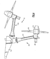
Figure 1 , a ramair turbine assembly 10 includes adeployable support structure 14 pivotally attached to afixed structure 12. A rotatingturbine hub 16 includesturbine blades 18 and is supported on a distal end of thesupport structure 14. The rotatinghub 16 is supported on ahousing 22 attached to the end of thesupport structure 14. Thesupport structure 14 is movable about apivot 15 between astowed position 24 and a deployedposition 26. - The example ram
air turbine assembly 10 is shown and described by way of example, and other configurations and structures are within the contemplation of this invention. Further, the example ramair turbine assembly 10 operates to provide auxiliary power generation in the event that a primary power generating unit aboard an aircraft is not working as desired. In such a circumstance, the example ram airpower generating assembly 10 is moved from thestowed position 24 to the deployedposition 26 and theturbine blades 18 rotate responsive to the airflow. The rotatingturbine blades 18 andhub 16 drive through mechanical means such as a mechanical transmission or hydraulic circuit, a generator and/or pump to provide electrical or hydraulic power. - Because the rotating
central hub 16 andblades 18 are supported at the end of thesupport structure 14, a structural resonance frequency can be attained during operation. The structural resonance frequency can induce high oscillating loads that are transferred to the aircraft structure. Accordingly, the exampleram air turbine 10 includes a preferentially locatedmass 20 that modifies and/or reduces the magnitude of the resonance response to acceptable levels. In the illustrated example, themass 20 is mounted to the rotatinghub 16. The location of themass 20 is determined to shift away from the structural resonance frequency such that resonance occurs only outside of desired operating ranges and conditions. The resulting shift of the structural resonance frequency reduces and/or eliminates vibrations that can occur within normal desired operating ranges. - Additionally, the
mass 20 can mitigate the resonance frequency by providing a counterbalance function, shifting the location of a node point to the location where the unbalance occurs within the ramair turbine assembly 10. The node point is that point in the physical structure that does not move during vibration. An unbalanced force at this node point, such as a spring imbalance, eliminates the effect of the resonance to thereby reduce and/or eliminate the vibration. - In one example, the
mass 20 is mounted to the front of the rotatinghub 16.
The amount ofmass 20 provided is determined according to application specific parameters to tailor the resonance reduction to desired levels, or shift to desired frequencies. - Referring to
Figure 2 , theexample mass 20 includes aflange portion 28 withopenings 30 for fasteners to attach the mass to thehub 16. Themass 20 itself is rounded and provided in a shape that limits negative aerodynamic effects on operation of the ramair turbine assembly 10. Themass 20 can be constructed of any compatible material to provide the desired weight in the defined space at the front of thehub 16. Further, it is within the contemplation of this invention to use alternate mass shapes and sizes. - Referring to
Figure 3 , anothermass 32 is illustrated and includes aninsert 34 of material with a greater density to increase the weight without increasing the volume. Theexample mass 32 includes aflange 36 providing for attachment to theturbine hub 16. As appreciated, althoughopenings 30 are shown, other fastening means as are known are within the contemplation of this invention. Additionally, themass 32 could be an integral feature of theturbine hub 16. - Referring to
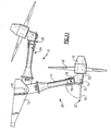
Figure 4 , another example ramair turbine assembly 10 includes anexample mass 38 attached to a rear portion of thehousing 22. Theexample mass 38 is substantially cylindrical and extends outward from thehousing 22. Themass 38 may also be any desired shape such as rectangular or any other shape as is desired to provide the desired dampening characteristics and also to ease storability. The location of themass 38 on thehousing 22 provides another example location that can be utilized to modify the resonance frequency of the structure without increasing the size and weight of the structural components of the ramair turbine assembly 10. - Referring to
Figure 5 , adeployable mass 40 is shown that folds into anon-extended position 25 when the ramair turbine assembly 10 is in the stowedposition 24. Because themass 40 is movable, less space is required when in the stowed position, such that modifications are not required to the storage space required for theoverall assembly 10. Further, because themass 40 is stowable, it may be longer than a comparable fixed mass to extend outward a further distance from thehousing 22. The added distance provides for a reduced weight of themass 40 while still providing the desired moment of inertia to suitably alter the structural resonance. - The
deployable mass 40 is pivotally attached to and rotatable about thepivot 44. Theexample pivot 44 is disposed on thehousing 22, but may be disposed on thestructure 14. Themass 40 is held in place against thestructure 14 by alatch 48. - Referring to
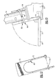
Figure 6 , themass 40 includes atab 46 that engages thelatch 48 to secure themass 40 until a desired deployedposition 26 of theassembly 10 is reached. Once the desired deployed position of the ramair turbine assembly 10 is obtained, thetab 46 moves free of thelatch 48 and allows themass 40 to fall free to anextended position 27. - Referring to
Figure 7 , an enlarged view of thelatch 48 illustrates movement of thetab 46 along thelatch 48 to a position at theend 50 that releases thetab 46 and provides for the mass 40 to fall to the deployed position. - Referring to
Figures 8-10 , anotherdeployable mass 52 is pivotally attached to thehousing 22 and is held in place by anut 64 on theturbine drive shaft 65. In this example, thedeployable mass 52 remains in thenon-extended position 66 until thedrive shaft 65 begins rotating within thenut 64. Rotation of theshaft 65 disengages the mass 52 so that it may fall into the desiredextended position 68. - The deployable mass includes a
latch 60 with anopening 62 that engages thenut 64. Themass 52 is pivotally attached by way ofpivot members 58 to thehousing 22. In the stowednon-extended position 25 of themass 52, thelatch 60 is engaged to thenut 64. Engagement of thelatch 60 to thenut 64 can be a slight interference fit to hold themass 52 against the supporting structure until movement breaks the interference fit to release themass 52. Further, thelatch 60 may include an integral threaded member that unthreads upon rotation of theshaft 65. - Once the
assembly 10 is deployedturbine drive shaft 65 begins rotating and disengages fromnut 64, thelatch 60 andnut 64 is freed and thedeployable mass 52 falls into theextended position 68. Anarm 54 extends outwardly on an opposite side of thepivot 58 relative to themass 52. Thearm 54 extends at an angle relative to themass 52 to engage astop 56. Once thearm 54 engages thestop 56, themass 52 is stopped in the desiredextended position 68. The angle of thearm 54 provides for the positioning of the mass 52 once thelatch 60 is free of thenut 64. - Referring to
Figure 11 , anotherdeployable mass 70 is held in thenon-extended position 25 by alatch member 76. Thelatch member 76 is a pivot arm that moves responsive to anactuator 78. The example actuator is a cylinder that pushes a shaft upward to move an opposite end of thelatch member 76 downward and free of themass 70. The mass then falls freely into the desiredextended position 27. - Referring to
Figures 12-14 , themass 70 includesarms 72 that are attached to thehousing 22 bypivot members 74. Themass 70 andarms 72 are shaped to include acatch portion 82. Theexample catch portion 82 is a step that is engaged by atab 80 on thelatch member 76. Thelatch member 76 can pivot about a pivot point 75. Theactuator 78, is disposed on an opposite side of thelatch member 76 andstructure 14 from themass 70. Theexample actuator 78 pushes upward on one end of thelatch member 76 to cause a corresponding downward movement of thetab 80 to release thecatch portion 82 and allow themass 70 to fall into the desired extended position. - Referring to
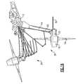
Figures 15 and16 , anotherdeployable mass 90 is attached to thehousing 22 and is moved between the non-extended and extended positions by a mechanical linkage 88. The example linkage 88 is a four bar linkage and comprises afirst link 92 attached tosecond link 94 at thepivot 96. Thesecond link 94 is in turn pivotally attached to themass 90. In this example, themass 90 extends together with deployment of the ramair turbine assembly 10. As thesupport structure 14 pivots downwardly, thefirst link 92 causes a corresponding pivoting movement of thesecond link 96, which in turn results in movement of the mass 90 to the extended position. - The resulting extension of the
mass 90 is controlled throughout and can be reversed to move from the extended position back to the non-extended position automatically. Accordingly, the lengths and pivot points of thelinks mass 90, and the corresponding movement therebetween. - Accordingly, the preferential location of masses described by way of example modifies the resonant structural frequency of the ram air turbine structure to reduce vibration in desired operational ranges. Further, the example masses can be movable so additional space is not required for storage of the ram air turbine. The preferential location of mass at specific locations on the ram air turbine shift structural resonance frequencies away from vibration frequencies that occur during normal operating conditions, thereby reducing the need to increase structural features of the overall ram
air turbine assembly 10. - Although a preferred embodiment of this invention has been disclosed, a worker of ordinary skill in this art would recognize that certain modifications would come within the scope of this invention. For that reason, the following claims should be studied to determine the true scope and content of this invention.
Claims (15)
- A ram air turbine assembly (10) comprising:a turbine comprising a turbine hub (16) and turbine blades (18) extending from the central hub;a support structure (14) supporting the turbine, wherein the support structure is movable between a stowed position and a deployed position; anda mass (20,32,38,40,52,70,90) located on one of the turbine and the support structure for adjusting a resonance frequency of the ram air turbine assembly.
- The assembly as recited in claim 1, wherein the mass (20,32,38) is located on the turbine hub.
- The assembly as recited in claim 1, wherein the mass is attached to the support structure on a side opposite the central hub.
- The assembly as recited in claim 1, 2 or 3 wherein the mass is movable from a stowed position to a deployed position.
- The assembly as recited in claim 4, including a deployment device for moving the mass between the stowed and deployed positions.
- The assembly as recited in claim 5, wherein the deployment device comprises an arm pivotally attached to the support structure.
- The assembly as recited in claim 5 or 6, including a latch for selectively engaging a portion of the deployment device to hold the deployment device in a stowed position until the support structure reaches a desired position.
- The assembly as recited in claim 5, 6 or 7 wherein the deployment device comprises a linkage pivotally attached at a first end to the mass and on a second end to a fixed structure, such that movement of the structural support drives the linkage to move the mass to the deployed position.
- The assembly as recited in claim 8, wherein the linkage comprises a four bar linkage.
- The assembly as recited in claim 1 wherein the mass is pivotally mounted to a support structure of the ram air turbine; and comprising an actuator for moving the mass from a stowed position to a deployed position, wherein the deployed position locates the mass in a desired position to modify a structural resonance of the ram air turbine.
- A mass deployment assembly for a ram air turbine, the mass deployment assembly comprising:a mass pivotally mounted to a support structure of the ram air turbine; andan actuator for moving the mass from a stowed position to a deployed position, wherein the deployed position locates the mass in a desired position to modify a structural resonance of the ram air turbine.
- The assembly as recited in claim 10 or 11, wherein the actuator comprises a linkage attached at a first end to the mass and at a second end to a fixed structure.
- The assembly as recited in claim 10, 11 or 12 wherein the mass comprises an arm pivotally attached to a support structure of the ram air turbine.
- The assembly as recited in claim 13, including a latch for selectively releasing the mass from the stowed position.
- The assembly as recited in claim 14, wherein the latch comprises a hook and the arm comprises a tab released from the hook when the support structure reaches a desired position; or
wherein the latch is engaged to a movable member of the ram air turbine such that movement of the ram air turbine releases the arm; or
wherein the latch is selectively operated by the actuator.
Applications Claiming Priority (1)
| Application Number | Priority Date | Filing Date | Title |
|---|---|---|---|
| US12/341,040 US8814520B2 (en) | 2008-12-22 | 2008-12-22 | Resonance reduction device for ram air turbine |
Publications (3)
| Publication Number | Publication Date |
|---|---|
| EP2199205A2 true EP2199205A2 (en) | 2010-06-23 |
| EP2199205A3 EP2199205A3 (en) | 2013-07-17 |
| EP2199205B1 EP2199205B1 (en) | 2014-07-30 |
Family
ID=42046421
Family Applications (1)
| Application Number | Title | Priority Date | Filing Date |
|---|---|---|---|
| EP09252865.2A Active EP2199205B1 (en) | 2008-12-22 | 2009-12-22 | Resonance reduction device for ram air turbine |
Country Status (2)
| Country | Link |
|---|---|
| US (1) | US8814520B2 (en) |
| EP (1) | EP2199205B1 (en) |
Cited By (5)
| Publication number | Priority date | Publication date | Assignee | Title |
|---|---|---|---|---|
| US8876474B2 (en) | 2010-11-04 | 2014-11-04 | Hamilton Sundstrand Corporation | Ram air turbine startup |
| US9045983B2 (en) | 2010-10-19 | 2015-06-02 | Hamilton Sundstrand Corporation | Turbine yokeplate flyweights to improve RAT startup |
| EP3633146A1 (en) * | 2018-10-05 | 2020-04-08 | Hamilton Sundstrand Corporation | Ram air turbine single-unit nose |
| EP3786066A1 (en) * | 2019-08-27 | 2021-03-03 | Pratt & Whitney Canada Corp. | Fan nose cone and dynamic tuning of aircrafts |
| EP4177165A1 (en) * | 2021-11-04 | 2023-05-10 | Hamilton Sundstrand Corporation | Strut for ram air turbine with inner damper rod |
Families Citing this family (5)
| Publication number | Priority date | Publication date | Assignee | Title |
|---|---|---|---|---|
| US20120237347A1 (en) * | 2011-03-18 | 2012-09-20 | Hamilton Sundstrand Corporation | Ram Air Turbine with Controlled Vibrational Resonances |
| US9598980B2 (en) | 2012-04-27 | 2017-03-21 | Hamilton Sundstrand Corporation | Turbine lock plunger for ram air turbine assembly |
| US10787274B2 (en) * | 2016-08-16 | 2020-09-29 | Hamilton Sundstrand Corporation | Inflight stow of ram air turbine |
| CN114483691A (en) * | 2021-12-30 | 2022-05-13 | 中国航空工业集团公司金城南京机电液压工程研究中心 | Hydraulic pump supporting arm oil circuit structure of ram air turbine system |
| US11794876B1 (en) * | 2022-04-08 | 2023-10-24 | Hamilton Sundstrand Corporation | Ram air turbine including damping element to vary natural frequency |
Family Cites Families (6)
| Publication number | Priority date | Publication date | Assignee | Title |
|---|---|---|---|---|
| US4411596A (en) * | 1980-03-25 | 1983-10-25 | Sundstrand Corporation | Ram air turbine control system |
| DE102004014992A1 (en) | 2004-03-26 | 2005-10-13 | Hofmann Mess- Und Auswuchttechnik Gmbh & Co. Kg | Balancing device for compensating the imbalance of rotors of wind turbines |
| US7416392B2 (en) * | 2005-09-07 | 2008-08-26 | Hamilton Sundstrand Corporation | Stow abort mechanism for a ram air turbine |
| US7931438B2 (en) * | 2006-12-13 | 2011-04-26 | General Electric Company | Active tower damper |
| WO2008104837A1 (en) * | 2007-02-28 | 2008-09-04 | Paulo Emmanuel De Abreu | Structure for supporting electric power transmission lines |
| US20090096213A1 (en) * | 2007-10-12 | 2009-04-16 | Berglund Jerry W | Vertical axis wind turbine and method of making the same |
-
2008
- 2008-12-22 US US12/341,040 patent/US8814520B2/en active Active
-
2009
- 2009-12-22 EP EP09252865.2A patent/EP2199205B1/en active Active
Non-Patent Citations (1)
| Title |
|---|
| None |
Cited By (7)
| Publication number | Priority date | Publication date | Assignee | Title |
|---|---|---|---|---|
| US9045983B2 (en) | 2010-10-19 | 2015-06-02 | Hamilton Sundstrand Corporation | Turbine yokeplate flyweights to improve RAT startup |
| US8876474B2 (en) | 2010-11-04 | 2014-11-04 | Hamilton Sundstrand Corporation | Ram air turbine startup |
| US9205928B2 (en) | 2010-11-04 | 2015-12-08 | Rosemount Aerospace, Inc. | Ram air turbine startup |
| EP3633146A1 (en) * | 2018-10-05 | 2020-04-08 | Hamilton Sundstrand Corporation | Ram air turbine single-unit nose |
| US10823151B2 (en) | 2018-10-05 | 2020-11-03 | Hamilton Sunstrand Corporation | Ram air turbine single-unit nose mass |
| EP3786066A1 (en) * | 2019-08-27 | 2021-03-03 | Pratt & Whitney Canada Corp. | Fan nose cone and dynamic tuning of aircrafts |
| EP4177165A1 (en) * | 2021-11-04 | 2023-05-10 | Hamilton Sundstrand Corporation | Strut for ram air turbine with inner damper rod |
Also Published As
| Publication number | Publication date |
|---|---|
| EP2199205A3 (en) | 2013-07-17 |
| US20100158698A1 (en) | 2010-06-24 |
| EP2199205B1 (en) | 2014-07-30 |
| US8814520B2 (en) | 2014-08-26 |
Similar Documents
| Publication | Publication Date | Title |
|---|---|---|
| EP2199205B1 (en) | Resonance reduction device for ram air turbine | |
| CA1136051A (en) | Automatic storm protection control for wind energy system | |
| EP3176082B1 (en) | A vortex generator arrangement for an aircraft | |
| CN103089540B (en) | Method For Shut Down Of A Wind Turbine | |
| JP2006520871A5 (en) | ||
| US20120328436A1 (en) | Electromechanical actuator driven governor for ram air turbine | |
| CN103089535A (en) | Wind turbine blade | |
| JP2011021609A (en) | Wind turbine | |
| CN102102733A (en) | Vibration damping mechanism and aircraft | |
| BE1021684B1 (en) | A ROTOR WHOLE FOR A WIND TURBINE WITH A CABLE COUPLE | |
| US9598980B2 (en) | Turbine lock plunger for ram air turbine assembly | |
| WO2010135552A2 (en) | Centrifugally driven aerodynamic rotor blade brake assembly | |
| JP7140331B2 (en) | Lift type vertical axis wind turbine | |
| JP2014181711A (en) | Failsafe device for load compensating device | |
| CN102926932B (en) | Automatic blade-changing speed-regulating device based on wind speed | |
| KR101416518B1 (en) | Antivibration suspension means for a tie bar of an aircraft power transmission gearbox, an antivibration suspension device, and an aircraft | |
| EP1764306A2 (en) | Auxiliary power unit case flange to cone bolt adapter | |
| JP2001221145A (en) | Passive active pitch flap mechanism | |
| CN112424468B (en) | Wind turbine with pivoting rotor blade, wire and release mechanism for stopping | |
| WO2004088131A1 (en) | Self-regulating wind turbine | |
| BE1021430B1 (en) | A ROTOR WHOLE FOR A WIND TURBINE | |
| WO2014083407A1 (en) | Wind turbine | |
| JP2008196464A (en) | Air brake structure for windmill | |
| EP4071349A1 (en) | Platform for a hub of a wind turbine | |
| US9045983B2 (en) | Turbine yokeplate flyweights to improve RAT startup |
Legal Events
| Date | Code | Title | Description |
|---|---|---|---|
| PUAI | Public reference made under article 153(3) epc to a published international application that has entered the european phase |
Free format text: ORIGINAL CODE: 0009012 |
|
| AK | Designated contracting states |
Kind code of ref document: A2 Designated state(s): AT BE BG CH CY CZ DE DK EE ES FI FR GB GR HR HU IE IS IT LI LT LU LV MC MK MT NL NO PL PT RO SE SI SK SM TR |
|
| AX | Request for extension of the european patent |
Extension state: AL BA RS |
|
| PUAL | Search report despatched |
Free format text: ORIGINAL CODE: 0009013 |
|
| AK | Designated contracting states |
Kind code of ref document: A3 Designated state(s): AT BE BG CH CY CZ DE DK EE ES FI FR GB GR HR HU IE IS IT LI LT LU LV MC MK MT NL NO PL PT RO SE SI SK SM TR |
|
| AX | Request for extension of the european patent |
Extension state: AL BA RS |
|
| RIC1 | Information provided on ipc code assigned before grant |
Ipc: B64D 41/00 20060101AFI20130610BHEP |
|
| 17P | Request for examination filed |
Effective date: 20140117 |
|
| RBV | Designated contracting states (corrected) |
Designated state(s): AT BE BG CH CY CZ DE DK EE ES FI FR GB GR HR HU IE IS IT LI LT LU LV MC MK MT NL NO PL PT RO SE SI SK SM TR |
|
| GRAP | Despatch of communication of intention to grant a patent |
Free format text: ORIGINAL CODE: EPIDOSNIGR1 |
|
| INTG | Intention to grant announced |
Effective date: 20140411 |
|
| GRAS | Grant fee paid |
Free format text: ORIGINAL CODE: EPIDOSNIGR3 |
|
| GRAA | (expected) grant |
Free format text: ORIGINAL CODE: 0009210 |
|
| AK | Designated contracting states |
Kind code of ref document: B1 Designated state(s): AT BE BG CH CY CZ DE DK EE ES FI FR GB GR HR HU IE IS IT LI LT LU LV MC MK MT NL NO PL PT RO SE SI SK SM TR |
|
| REG | Reference to a national code |
Ref country code: GB Ref legal event code: FG4D |
|
| REG | Reference to a national code |
Ref country code: CH Ref legal event code: EP |
|
| REG | Reference to a national code |
Ref country code: AT Ref legal event code: REF Ref document number: 679827 Country of ref document: AT Kind code of ref document: T Effective date: 20140815 |
|
| REG | Reference to a national code |
Ref country code: IE Ref legal event code: FG4D |
|
| REG | Reference to a national code |
Ref country code: DE Ref legal event code: R096 Ref document number: 602009025632 Country of ref document: DE Effective date: 20140911 |
|
| REG | Reference to a national code |
Ref country code: AT Ref legal event code: MK05 Ref document number: 679827 Country of ref document: AT Kind code of ref document: T Effective date: 20140730 |
|
| REG | Reference to a national code |
Ref country code: NL Ref legal event code: VDEP Effective date: 20140730 |
|
| REG | Reference to a national code |
Ref country code: LT Ref legal event code: MG4D |
|
| PG25 | Lapsed in a contracting state [announced via postgrant information from national office to epo] |
Ref country code: FI Free format text: LAPSE BECAUSE OF FAILURE TO SUBMIT A TRANSLATION OF THE DESCRIPTION OR TO PAY THE FEE WITHIN THE PRESCRIBED TIME-LIMIT Effective date: 20140730 Ref country code: LT Free format text: LAPSE BECAUSE OF FAILURE TO SUBMIT A TRANSLATION OF THE DESCRIPTION OR TO PAY THE FEE WITHIN THE PRESCRIBED TIME-LIMIT Effective date: 20140730 Ref country code: NO Free format text: LAPSE BECAUSE OF FAILURE TO SUBMIT A TRANSLATION OF THE DESCRIPTION OR TO PAY THE FEE WITHIN THE PRESCRIBED TIME-LIMIT Effective date: 20141030 Ref country code: GR Free format text: LAPSE BECAUSE OF FAILURE TO SUBMIT A TRANSLATION OF THE DESCRIPTION OR TO PAY THE FEE WITHIN THE PRESCRIBED TIME-LIMIT Effective date: 20141031 Ref country code: PT Free format text: LAPSE BECAUSE OF FAILURE TO SUBMIT A TRANSLATION OF THE DESCRIPTION OR TO PAY THE FEE WITHIN THE PRESCRIBED TIME-LIMIT Effective date: 20141202 Ref country code: BG Free format text: LAPSE BECAUSE OF FAILURE TO SUBMIT A TRANSLATION OF THE DESCRIPTION OR TO PAY THE FEE WITHIN THE PRESCRIBED TIME-LIMIT Effective date: 20141030 Ref country code: ES Free format text: LAPSE BECAUSE OF FAILURE TO SUBMIT A TRANSLATION OF THE DESCRIPTION OR TO PAY THE FEE WITHIN THE PRESCRIBED TIME-LIMIT Effective date: 20140730 Ref country code: SE Free format text: LAPSE BECAUSE OF FAILURE TO SUBMIT A TRANSLATION OF THE DESCRIPTION OR TO PAY THE FEE WITHIN THE PRESCRIBED TIME-LIMIT Effective date: 20140730 |
|
| PG25 | Lapsed in a contracting state [announced via postgrant information from national office to epo] |
Ref country code: IS Free format text: LAPSE BECAUSE OF FAILURE TO SUBMIT A TRANSLATION OF THE DESCRIPTION OR TO PAY THE FEE WITHIN THE PRESCRIBED TIME-LIMIT Effective date: 20141130 Ref country code: NL Free format text: LAPSE BECAUSE OF FAILURE TO SUBMIT A TRANSLATION OF THE DESCRIPTION OR TO PAY THE FEE WITHIN THE PRESCRIBED TIME-LIMIT Effective date: 20140730 Ref country code: HR Free format text: LAPSE BECAUSE OF FAILURE TO SUBMIT A TRANSLATION OF THE DESCRIPTION OR TO PAY THE FEE WITHIN THE PRESCRIBED TIME-LIMIT Effective date: 20140730 Ref country code: AT Free format text: LAPSE BECAUSE OF FAILURE TO SUBMIT A TRANSLATION OF THE DESCRIPTION OR TO PAY THE FEE WITHIN THE PRESCRIBED TIME-LIMIT Effective date: 20140730 Ref country code: CY Free format text: LAPSE BECAUSE OF FAILURE TO SUBMIT A TRANSLATION OF THE DESCRIPTION OR TO PAY THE FEE WITHIN THE PRESCRIBED TIME-LIMIT Effective date: 20140730 Ref country code: LV Free format text: LAPSE BECAUSE OF FAILURE TO SUBMIT A TRANSLATION OF THE DESCRIPTION OR TO PAY THE FEE WITHIN THE PRESCRIBED TIME-LIMIT Effective date: 20140730 Ref country code: PL Free format text: LAPSE BECAUSE OF FAILURE TO SUBMIT A TRANSLATION OF THE DESCRIPTION OR TO PAY THE FEE WITHIN THE PRESCRIBED TIME-LIMIT Effective date: 20140730 |
|
| PG25 | Lapsed in a contracting state [announced via postgrant information from national office to epo] |
Ref country code: CZ Free format text: LAPSE BECAUSE OF FAILURE TO SUBMIT A TRANSLATION OF THE DESCRIPTION OR TO PAY THE FEE WITHIN THE PRESCRIBED TIME-LIMIT Effective date: 20140730 Ref country code: EE Free format text: LAPSE BECAUSE OF FAILURE TO SUBMIT A TRANSLATION OF THE DESCRIPTION OR TO PAY THE FEE WITHIN THE PRESCRIBED TIME-LIMIT Effective date: 20140730 Ref country code: IT Free format text: LAPSE BECAUSE OF FAILURE TO SUBMIT A TRANSLATION OF THE DESCRIPTION OR TO PAY THE FEE WITHIN THE PRESCRIBED TIME-LIMIT Effective date: 20140730 Ref country code: RO Free format text: LAPSE BECAUSE OF FAILURE TO SUBMIT A TRANSLATION OF THE DESCRIPTION OR TO PAY THE FEE WITHIN THE PRESCRIBED TIME-LIMIT Effective date: 20140730 Ref country code: DK Free format text: LAPSE BECAUSE OF FAILURE TO SUBMIT A TRANSLATION OF THE DESCRIPTION OR TO PAY THE FEE WITHIN THE PRESCRIBED TIME-LIMIT Effective date: 20140730 Ref country code: SK Free format text: LAPSE BECAUSE OF FAILURE TO SUBMIT A TRANSLATION OF THE DESCRIPTION OR TO PAY THE FEE WITHIN THE PRESCRIBED TIME-LIMIT Effective date: 20140730 |
|
| REG | Reference to a national code |
Ref country code: DE Ref legal event code: R097 Ref document number: 602009025632 Country of ref document: DE |
|
| PLBE | No opposition filed within time limit |
Free format text: ORIGINAL CODE: 0009261 |
|
| STAA | Information on the status of an ep patent application or granted ep patent |
Free format text: STATUS: NO OPPOSITION FILED WITHIN TIME LIMIT |
|
| PG25 | Lapsed in a contracting state [announced via postgrant information from national office to epo] |
Ref country code: BE Free format text: LAPSE BECAUSE OF NON-PAYMENT OF DUE FEES Effective date: 20141231 |
|
| REG | Reference to a national code |
Ref country code: DE Ref legal event code: R119 Ref document number: 602009025632 Country of ref document: DE |
|
| 26N | No opposition filed |
Effective date: 20150504 |
|
| PG25 | Lapsed in a contracting state [announced via postgrant information from national office to epo] |
Ref country code: LU Free format text: LAPSE BECAUSE OF FAILURE TO SUBMIT A TRANSLATION OF THE DESCRIPTION OR TO PAY THE FEE WITHIN THE PRESCRIBED TIME-LIMIT Effective date: 20141222 |
|
| REG | Reference to a national code |
Ref country code: CH Ref legal event code: PL |
|
| REG | Reference to a national code |
Ref country code: IE Ref legal event code: MM4A |
|
| PG25 | Lapsed in a contracting state [announced via postgrant information from national office to epo] |
Ref country code: IE Free format text: LAPSE BECAUSE OF NON-PAYMENT OF DUE FEES Effective date: 20141222 Ref country code: LI Free format text: LAPSE BECAUSE OF NON-PAYMENT OF DUE FEES Effective date: 20141231 Ref country code: DE Free format text: LAPSE BECAUSE OF NON-PAYMENT OF DUE FEES Effective date: 20150701 Ref country code: CH Free format text: LAPSE BECAUSE OF NON-PAYMENT OF DUE FEES Effective date: 20141231 |
|
| REG | Reference to a national code |
Ref country code: FR Ref legal event code: PLFP Year of fee payment: 7 |
|
| PG25 | Lapsed in a contracting state [announced via postgrant information from national office to epo] |
Ref country code: SI Free format text: LAPSE BECAUSE OF FAILURE TO SUBMIT A TRANSLATION OF THE DESCRIPTION OR TO PAY THE FEE WITHIN THE PRESCRIBED TIME-LIMIT Effective date: 20140730 |
|
| PG25 | Lapsed in a contracting state [announced via postgrant information from national office to epo] |
Ref country code: SM Free format text: LAPSE BECAUSE OF FAILURE TO SUBMIT A TRANSLATION OF THE DESCRIPTION OR TO PAY THE FEE WITHIN THE PRESCRIBED TIME-LIMIT Effective date: 20140730 |
|
| PG25 | Lapsed in a contracting state [announced via postgrant information from national office to epo] |
Ref country code: MC Free format text: LAPSE BECAUSE OF FAILURE TO SUBMIT A TRANSLATION OF THE DESCRIPTION OR TO PAY THE FEE WITHIN THE PRESCRIBED TIME-LIMIT Effective date: 20140730 |
|
| PG25 | Lapsed in a contracting state [announced via postgrant information from national office to epo] |
Ref country code: HU Free format text: LAPSE BECAUSE OF FAILURE TO SUBMIT A TRANSLATION OF THE DESCRIPTION OR TO PAY THE FEE WITHIN THE PRESCRIBED TIME-LIMIT; INVALID AB INITIO Effective date: 20091222 Ref country code: MT Free format text: LAPSE BECAUSE OF FAILURE TO SUBMIT A TRANSLATION OF THE DESCRIPTION OR TO PAY THE FEE WITHIN THE PRESCRIBED TIME-LIMIT Effective date: 20140730 Ref country code: TR Free format text: LAPSE BECAUSE OF FAILURE TO SUBMIT A TRANSLATION OF THE DESCRIPTION OR TO PAY THE FEE WITHIN THE PRESCRIBED TIME-LIMIT Effective date: 20140730 Ref country code: BE Free format text: LAPSE BECAUSE OF FAILURE TO SUBMIT A TRANSLATION OF THE DESCRIPTION OR TO PAY THE FEE WITHIN THE PRESCRIBED TIME-LIMIT Effective date: 20140730 |
|
| REG | Reference to a national code |
Ref country code: FR Ref legal event code: PLFP Year of fee payment: 8 |
|
| REG | Reference to a national code |
Ref country code: FR Ref legal event code: PLFP Year of fee payment: 9 |
|
| PG25 | Lapsed in a contracting state [announced via postgrant information from national office to epo] |
Ref country code: MK Free format text: LAPSE BECAUSE OF FAILURE TO SUBMIT A TRANSLATION OF THE DESCRIPTION OR TO PAY THE FEE WITHIN THE PRESCRIBED TIME-LIMIT Effective date: 20140730 |
|
| P01 | Opt-out of the competence of the unified patent court (upc) registered |
Effective date: 20230522 |
|
| PGFP | Annual fee paid to national office [announced via postgrant information from national office to epo] |
Ref country code: GB Payment date: 20231121 Year of fee payment: 15 |
|
| PGFP | Annual fee paid to national office [announced via postgrant information from national office to epo] |
Ref country code: FR Payment date: 20231122 Year of fee payment: 15 |