EP2199202A2 - Bleed leakage detection system and method - Google Patents
Bleed leakage detection system and method Download PDFInfo
- Publication number
- EP2199202A2 EP2199202A2 EP09015726A EP09015726A EP2199202A2 EP 2199202 A2 EP2199202 A2 EP 2199202A2 EP 09015726 A EP09015726 A EP 09015726A EP 09015726 A EP09015726 A EP 09015726A EP 2199202 A2 EP2199202 A2 EP 2199202A2
- Authority
- EP
- European Patent Office
- Prior art keywords
- temperature
- sensitive
- thermostat
- devices
- elements
- Prior art date
- Legal status (The legal status is an assumption and is not a legal conclusion. Google has not performed a legal analysis and makes no representation as to the accuracy of the status listed.)
- Granted
Links
- 238000001514 detection method Methods 0.000 title claims abstract description 34
- 238000000034 method Methods 0.000 title claims description 12
- 238000012360 testing method Methods 0.000 claims abstract description 28
- 238000012544 monitoring process Methods 0.000 claims abstract description 20
- 238000010438 heat treatment Methods 0.000 claims description 15
- 230000004044 response Effects 0.000 claims description 9
- 230000008859 change Effects 0.000 claims description 7
- 230000031070 response to heat Effects 0.000 claims 2
- 230000003213 activating effect Effects 0.000 claims 1
- 230000001143 conditioned effect Effects 0.000 claims 1
- 238000012423 maintenance Methods 0.000 abstract description 3
- 230000000737 periodic effect Effects 0.000 abstract description 3
- 239000007789 gas Substances 0.000 description 6
- 230000002159 abnormal effect Effects 0.000 description 5
- 238000005516 engineering process Methods 0.000 description 5
- 239000002184 metal Substances 0.000 description 5
- 229910052751 metal Inorganic materials 0.000 description 5
- 238000010586 diagram Methods 0.000 description 4
- 230000009471 action Effects 0.000 description 2
- 230000007423 decrease Effects 0.000 description 2
- 238000009429 electrical wiring Methods 0.000 description 2
- 108010076504 Protein Sorting Signals Proteins 0.000 description 1
- 239000000654 additive Substances 0.000 description 1
- 230000000996 additive effect Effects 0.000 description 1
- 238000013459 approach Methods 0.000 description 1
- 238000005452 bending Methods 0.000 description 1
- 230000001010 compromised effect Effects 0.000 description 1
- 230000001419 dependent effect Effects 0.000 description 1
- 238000011161 development Methods 0.000 description 1
- 239000000446 fuel Substances 0.000 description 1
- 238000007689 inspection Methods 0.000 description 1
- 230000007257 malfunction Effects 0.000 description 1
- 238000004519 manufacturing process Methods 0.000 description 1
- 150000002739 metals Chemical class 0.000 description 1
- 238000012806 monitoring device Methods 0.000 description 1
- 238000013021 overheating Methods 0.000 description 1
- 230000008569 process Effects 0.000 description 1
- 238000011160 research Methods 0.000 description 1
- 230000006903 response to temperature Effects 0.000 description 1
- 239000012266 salt solution Substances 0.000 description 1
- 230000011664 signaling Effects 0.000 description 1
Images


Classifications
-
- B—PERFORMING OPERATIONS; TRANSPORTING
- B64—AIRCRAFT; AVIATION; COSMONAUTICS
- B64D—EQUIPMENT FOR FITTING IN OR TO AIRCRAFT; FLIGHT SUITS; PARACHUTES; ARRANGEMENT OR MOUNTING OF POWER PLANTS OR PROPULSION TRANSMISSIONS IN AIRCRAFT
- B64D13/00—Arrangements or adaptations of air-treatment apparatus for aircraft crew or passengers, or freight space, or structural parts of the aircraft
-
- G—PHYSICS
- G01—MEASURING; TESTING
- G01K—MEASURING TEMPERATURE; MEASURING QUANTITY OF HEAT; THERMALLY-SENSITIVE ELEMENTS NOT OTHERWISE PROVIDED FOR
- G01K15/00—Testing or calibrating of thermometers
- G01K15/007—Testing
-
- G—PHYSICS
- G01—MEASURING; TESTING
- G01K—MEASURING TEMPERATURE; MEASURING QUANTITY OF HEAT; THERMALLY-SENSITIVE ELEMENTS NOT OTHERWISE PROVIDED FOR
- G01K3/00—Thermometers giving results other than momentary value of temperature
- G01K3/005—Circuits arrangements for indicating a predetermined temperature
-
- G—PHYSICS
- G01—MEASURING; TESTING
- G01M—TESTING STATIC OR DYNAMIC BALANCE OF MACHINES OR STRUCTURES; TESTING OF STRUCTURES OR APPARATUS, NOT OTHERWISE PROVIDED FOR
- G01M3/00—Investigating fluid-tightness of structures
- G01M3/002—Investigating fluid-tightness of structures by using thermal means
-
- B—PERFORMING OPERATIONS; TRANSPORTING
- B64—AIRCRAFT; AVIATION; COSMONAUTICS
- B64D—EQUIPMENT FOR FITTING IN OR TO AIRCRAFT; FLIGHT SUITS; PARACHUTES; ARRANGEMENT OR MOUNTING OF POWER PLANTS OR PROPULSION TRANSMISSIONS IN AIRCRAFT
- B64D13/00—Arrangements or adaptations of air-treatment apparatus for aircraft crew or passengers, or freight space, or structural parts of the aircraft
- B64D13/06—Arrangements or adaptations of air-treatment apparatus for aircraft crew or passengers, or freight space, or structural parts of the aircraft the air being conditioned
- B64D2013/0603—Environmental Control Systems
- B64D2013/0618—Environmental Control Systems with arrangements for reducing or managing bleed air, using another air source, e.g. ram air
-
- Y—GENERAL TAGGING OF NEW TECHNOLOGICAL DEVELOPMENTS; GENERAL TAGGING OF CROSS-SECTIONAL TECHNOLOGIES SPANNING OVER SEVERAL SECTIONS OF THE IPC; TECHNICAL SUBJECTS COVERED BY FORMER USPC CROSS-REFERENCE ART COLLECTIONS [XRACs] AND DIGESTS
- Y02—TECHNOLOGIES OR APPLICATIONS FOR MITIGATION OR ADAPTATION AGAINST CLIMATE CHANGE
- Y02T—CLIMATE CHANGE MITIGATION TECHNOLOGIES RELATED TO TRANSPORTATION
- Y02T50/00—Aeronautics or air transport
- Y02T50/50—On board measures aiming to increase energy efficiency
Definitions
- the technology herein relates to pneumatic system testing and failure detection, and more particularly to aircraft pneumatic systems where engine bleed provides pressurized hot air to air bleed ducts.
- the technology herein further relates to gas turbine aircraft engines and aircraft engine airflow control, and to bleed airflow leakage detection.
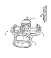
- gas turbine engines 10 of the type commonly found on many aircraft include a compressor 20, a combuster 30 and a turbine 40.
- the compressor 20 compresses air which is then mixed with fuel for combustor 30 to ignite.
- the combustor 30 exhausts gases which turn the vanes of the turbine(s) 40. Power from the rotating turbine 40 operates the compressor 20.
- Turbine engine compressors can be designed to supply more compressed heated air than is needed to operate the engine 10. This additional compressed air from the compressor 20 can be used for tasks other than feeding the combustor 30. For example, it is common to bleed some of the compressed air from the compressor 20 and route the bleed air to other equipment onboard the aircraft such as de-icers, cabin pressurization systems and the like.
- bleed leakage detection systems to detect when leakage from the bleed air system occurs. Because the bleed air is heated by the gas turbine engines, it is common to use temperature sensing to detect bleed air leakage.
- thermal switches have been used in the past.
- a common form of thermal switch is the simple thermostat of the type that controls central heating in many homes throughout the world.
- Such a thermal switch consists of two metal strips having different thermal expansion coefficients.
- Such well known bimetallic strips flex or bend in response to temperature changes. When temperature exceeds a predetermined level, thermal expansion between the two different metals provides enough bending force to cause the bimetal strip to move close electrical contacts.
- thermal switches are highly reliable and can be used in bleed air leakage detection systems.
- thermostats near each point where the bleed air duct is joined with another section of duct work. If leakage develops, the air surrounding the ductwork joint increases in temperature and the resulting heating provides sufficient energy to actuate the thermostatic thermal switch.
- ODS Overheat Detection System
- a cable externally installed in parallel with the bleed duct includes two resistive wires that are immersed in a special salt solution.
- electronics e.g., a microprocessor
- this Overheat Detection System is able to detect the exact place where the leakage is occurring.
- the Overheat Detection System is a relatively expensive and complex system.
- the sensors comprise surface sensors consisting of cylindrical wires a few millimeters thick that contain, between the core and sheath, a filling that has a temperature-dependent electrical resistance. Below a certain response temperature (which can be set within certain limits during production), the resistance is high. If the temperature exceeds a predetermined temperature, the sensor resistance abruptly decreases by several orders of magnitude. Such a change in resistance can be electronically detected by a monitoring device. If hot air emerges from the pipeworks system through a leak, the hot air heats the surrounding sensors until the sensors exceed the predetermined response temperature. The monitoring system detects a leak and responds to the abrupt change in resistance. Additional electronics in the monitoring system is able to control elements that interrupt the air supply in the leaking section by for example closing a shutoff valve.
- a further know prior art arrangement uses a thermal switch connected in series with the shutoff valve and also includes a monitoring control device.
- the thermal switch interrupts the shutoff circuit whenever a predetermined limit temperature within the bleed air duct has been exceeded.
- the thermal switch prevents possible overheating relating to the temperature within the bleed duct.
- thermostats have been developed and optimized in an attempt to improve bleed leakage detection reliability and low cost.
- a technical challenge is to attain an acceptable level of reliability.
- the commonly available thermostatic thermal switch is considered to be highly reliable, the ratio between the thermostat failure rate and duct leakage failure rate may still remain significant. Therefore, the probability is not negligible that a thermostat used to detect bleed air duct failure may have latently failed by the time duct leakage occurs. A thermostat latently fails when it has failed but its failure has not yet been detected.
- the exemplary illustrative non-limiting technology herein provides a bleed leakage detection system including an arrangement of series-connected, disparately placed thermostats.
- the bleed leakage detection system is capable of detecting the exact place where the bleed air leakage is occurring (e.g., the precise failed junction in bleed air duct work) by detecting which thermostat has opened. Such detection can be accomplished by monitoring voltage or current on a line that connects the thermostats in series with respective resistances.
- the exemplary illustrative non-limiting implementation also provides a sequential bleed leakage detection system thermostat self-test function ("Initiated Built In Test" - "IBIT”) which allows continuous monitoring of thermostat sensor wiring during flight. The pilot is alerted when the bleed leakage detection system has failed so that appropriate countermeasures and maintenance may be performed.
- Figure 1 shows an exemplary illustrative aircraft gas turbine engine
- Figure 2 shows an exemplary illustrative non-limiting bleed leakage detection system electrical schematic diagram
- FIG. 3 shows an exemplary illustrative non-limiting more detailed schematic diagram of an exemplary thermostat used in the Figure 2 system
- FIG 4 shows signals monitored from the Figure 2 circuit during normal operation in which no thermostat has failed
- Figure 5 shows exemplary illustrative non-limiting signal sequences indicating that a first thermostat switch A has failed
- Figure 6 shows exemplary illustrative non-limiting signaling occurring when a second thermostat switch B or thermostat heater fails
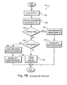
- Figures 7A and 7B show an exemplary illustrative non-limiting software-controlled algorithms for analyzing signals obtained from the Figure 2 circuit;
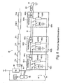
- Figure 8 shows an additional exemplary illustrative non-limiting bleed leakage detection system electrical schematic diagram
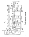
- Figure 9 shows an additional exemplary illustrative non-limiting bleed leakage detection system electrical schematic diagram.
- FIG. 2 shows an exemplary illustrative non-limiting thermostat leakage detection system 50.
- System 50 includes a plurality of thermostats 52(1), 52(2), 52(N).
- Each of thermostats 52 may be installed for example near a junction between two pieces of joined bleed air duct work 51 that route bleed air, and are preferably installed outside of the duct.
- system 50 continuously monitors, via electrical wiring that connects the various thermostats, the condition of each of the thermostats.
- This continuous electrical wiring monitoring may be performed for example by analog electronic circuit, a digital circuit, and/or by software that may be implemented and executed on a microprocessor 65.
- a self-test function (Initiated Built In Test - IBIT) is implemented using thermostat self-heating.
- small heaters are installed within each thermostat case. The heaters may be activated by a switch 56. The heaters, when activated, cause the thermostats 52 to switch. Such switching can be detected to verify that each of thermostats 52 is operating correctly.
- the IBIT self-testing can be initiated before the aircraft takes off or optionally, during periodic self testing that may be run during predetermined periods such as overnight when the aircraft is not being flown.
- Figures 4-6 show example signals obtained from an exemplary illustrative non-limiting IBIT self-testing operation
- 7B shows an exemplary illustrative non-limiting software-controlled IBIT self-testing algorithm.
- An additional feature provided by the exemplary illustrative non-limiting arrangement shown in Figure 2 is to identify the leakage zone using minimal hardware and associated weight and cost.
- a small resistor R t 58 is included within each of the various thermostats. This additional resistor 58 provides a specific known voltage drop that is related to the leakage zone.
- a microprocessor monitoring the voltage drop seen at one end of the connection can identify exactly which thermostat has switched in response to detected temperature increase.
- the exemplary illustrative non-limiting implementation may use software to detect and localize the leakage zone.
- An exemplary software algorithm (see Figure 7A ) may check the voltage variation that is caused by the thermostat actuation. This voltage variation may be used to detect and localize the leakage zone.
- each of thermostats 52 comprises a bi-metal thermostatic switch 60 that is normally open but which closes when ambient temperature exceeds a predetermined level.
- each of thermostatic switches 60 has two poles (A and B) and comprises a double pole single throw (DPST) switch.
- One of the poles (A) of each thermostat switch 60 is used to ground a sense line 64 in response to high ambient temperature detection.
- the bi-metal switch 60 A contacts remain open and sense line 64 is not connected to ground by means of one thermostat 52.
- the bi-metal switch 60 contacts close so that the A pole of the switch shunts the sense line 64 to ground.
- Each thermostat includes, within its housing 62, a resistor 58 of known value (e.g., 20 ohms ⁇ 1%).
- the resistors 58(1)... 58(N) are connected in series by the sense line 64.
- thermostat 52 In most cases, only one thermostat 52 is likely to detect high ambient temperature at a time, but even if multiple ones function properly to detect abnormal heat escaping from the bleed air duct, the system can automatically isolate the duct junction closest to the engine that has failed and take appropriate corrective action (e.g., actuate an air shutoff valve to prevent further hot air from escaping).
- each thermostat switch 60 is used to actuate the heater element 54 of the next thermostat 52 which is connected to the switch.
- the B pole of the thermostat switch 60(2) closes providing electrical power to the heater element 54(1) of the thermostat 52(1).
- the switch pole B of the thermostat switch 60(3) is connected to supply current to the heater 54(2) of the thermostat 52(2), and the pole B of the thermostat switch 60(N) is used to supply current to the heater 54(N-1) of thermostat 52(N-1).
- the very last heater 54(N) of the last thermostat 52(N) is connected directly between ground 68 and switch 56 in this particular embodiment.
- switch 56 closes, current is applied to this heater 54(N) which heats up sufficiently to cause switch 60(N) to close.
- switch 60(N) does not close instantly. Rather, there is a certain amount of time required once heater 54(N) has current supplied to it for the heater to heat up the thermostat 52(N) sufficiently to cause thermostat 60(N) to close.
- switch 60(N) When switch 60(N) closes, it delivers current to the heater 54(N-1) (of the next thermostat connected in series). That heater 54(N-1) in turn heats its associated switch 60(N-1) - which after a certain time period has passed, in turn closes to supply current to the next heater down the line.
- thermostat switch 60(3) This process continues until heater 54(2) is actuated by closure of thermostat switch 60(3).
- the heater 54(2) in turn heats thermostat switch 60(2) so that it closes, and causes current to be delivered to heater 54(1).
- heater 54(1) When heater 54(1) finally is actuated, it will, in turn, heat thermostat switch 60(1) sufficiently to close that switch and - if the system is functioning normally - thus cause all switches 60(N)-60(1) to close in sequence.
- Such closures can be detected by a microprocessor 65 that monitors the resistance or voltage on the series-connected sense line 64. See Figures 4-6 and 7B for example.
- N bl is the number of thermostats whose resistances R t 58 are in series in the electrical circuit formed when a thermostat switch 60 closes due to a detected leakage in its zone.
- [Rp + N bl * R t ] is the equivalent resistance in the electrical circuit.
- N lz N bl + 1
- N iz is the number (i.e., position number) of the thermostat installed in the leakage zone. From the number of the thermostat 52, it is possible to identify the leakage zone.
- V m V * N * Rt / Rp + N * Rt If V m exceeds the specified limit, then continuous monitoring software may provide a high impedance failure message such as "leakage detection system failure.” When this message is displayed, it means that the leakage detection system is not operating correctly but instead has failed. For example, breaking of a sense wire 64 or a poor connection between the different thermostats 52 can result in a high impedance failure.
- V m as monitored by microprocessor 65, drops below a specified limit (see Figure 7A ), then the continuous monitoring software may provide a "duct leakage" failure message.
- the software can localize precisely the leakage zone.
- the system 50 may also provide immediate automatic closing of a bleed valve BV. In other applications, the system need not take such immediate curative action but may simply display the failure mode on an operator display or report it automatically to maintenance personnel.
- microprocessor 65 may detect two different types of failures: (1) bleed air leakage, and (2) wiring short circuit in the bleed air detection system 50. For these two cases, the provided message is the same "duct leakage failure" (see Figure 7A ). Physical inspection within the zone of the failure indicated by the system can be used to detect whether the failure was caused by an actual leakage condition or by a short-circuit malfunction of the bleed leakage detection system.
- each thermostat 52 itself cannot detect by the continuous monitoring function because the continuous monitoring function only detects the wiring and leakage as described above. Therefore, in the exemplary illustrative non-limiting implementation, an "Initiated Built In Test" (IBIT) or periodic test is provided to test the condition of each of thermostats 52.
- the test may be initialized by mechanical switch when electrically actuated switch 56 is closed (see Figure 7B ).
- switch 56 When switch 56 is closed, it provides electrical power to energize sequentially all of the thermostat heaters 54.
- the heating sequence starts in thermostat 52(N) and continues down the line with each thermostat 52 in sequence until heater 54(1) is actuated. After some time has passed, all thermostats will be actuated and the last monitored voltage V m should be in the example shown in Figure 2 , approximately zero volts (note that since in Figure 3 the exemplary illustrative resistor 58 is connected on the other side of switch 60 contacts A the sense voltage in this case will not be substantially zero volts but will nevertheless be a minimum voltage).
- the amount of time required to complete this sequence of switch closures depends upon the heating power of each heater 50, thermostat thermal inertia, thermostat thermal conduction, thermostat quantity and possible other factors.
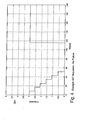
- FIG. 4 shows an example IBIT sequence when there is no failure and six thermostats connected in series are operating normally. It can be observed that each constant amplitude step drop in V m corresponds to an actuation of one of thermostats 52. When the test finishes, switch 56 is opened and the voltage V m returns to its initial value.
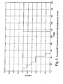
- FIG. 5 shows the behavior of V m when a thermostat switch 60 A contacts fails during the IBIT self test.
- the microprocessor 65 identifies the abnormal step amplitude and localizes the failed thermostat 52 using the following equations that are derived from equation number 2.
- V ma V * N ba * R t / R p + N ba * R t
- V ma the monitored voltage during the abnormal step amplitude (see Figure 5 )
- V is the supply voltage
- Nba is the number (i.e., quantity) of thermostats 52 whose R t resistance 58 values are in series in the electrical circuit when the system is converging to V ma (i.e., when the abnormal step amplitude is occurring).
- N ba is the number of thermostats that are connected in series before the last thermostat that worked correctly when the abnormal step occurred.
- R t is the value of the internal thermostat resistors 58
- R p is the value of pull-up resistor 66.
- N ba V ma * R p / R t * V - V ma
- N ba also represents the number (i.e., position number) of the thermostat 52 whose switch 60 A contacts failed.
- the system 50 provides a message indicating the position number of the thermostat whose switch A has failed.
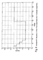
- FIG. 6 shows the behavior of V m when a thermostat switch 60 B contacts and/or a heater 54 fails during the IBIT self-test.
- V m never drops to a minimum value.
- N t V lm * R p / R t * V - V lm
- the system 50 may provide a message indicating the position number of the thermostat whose switch B or heater has failed.
- Figure 8 provides an additional resistor R f 200 may be provided. The above equations should be modified in order to consider this additional resistance R f 200.
- FIG 9 shows an additional exemplary illustrative non-limiting implementation that duplicates leakage detection reliability by continually monitoring the state of switch 60 contacts B as well as electrical contacts A.
- the IBIT wiring is used to perform this additional function. Reliability can be almost duplicated because two voltages are continuously monitored: V m and V m' where V m' is the voltage at an additional pull-up resistor R p' 304. Assuming R p' 304 has high impedance, V m' will trend toward a minimum voltage when any thermostat 52 is actuated.
- switch 302 is open to provide continual monitoring. In order to provide the self-test IBIT function, switch 302 is closed.
- exemplary illustrative non-limiting implementations described above have made use of an analog electronic or a microprocessor.
- one type of suitable microprocessor may be a microcontroller including an internal analog-to-digital converter that converts the analog level of V m (V m' ) to a digital value for testing and monitoring.
- V m' analog level of V m
- the resistor R t may be implemented in the wiring between the thermostats as opposed to within them.
- the described heaters 54 may be provided externally or attached to the thermostat cases 62 so that conventional off the shelf thermostats 52 can be used.
- NTC thermisters negative temperature coefficients or thermisters
Landscapes
- Physics & Mathematics (AREA)
- General Physics & Mathematics (AREA)
- Health & Medical Sciences (AREA)
- General Health & Medical Sciences (AREA)
- Pulmonology (AREA)
- Engineering & Computer Science (AREA)
- Aviation & Aerospace Engineering (AREA)
- Examining Or Testing Airtightness (AREA)
- Testing Of Short-Circuits, Discontinuities, Leakage, Or Incorrect Line Connections (AREA)
- Air Conditioning Control Device (AREA)
Abstract
Description
- This application is related to commonly assigned copending
U.S. Patent Application No. 12/023,585 filed January 31, 2008 , entitled "Bleed Airflow Balancing Control Using Simplified Sensing" (attorney docket 4439-53). -
- The technology herein relates to pneumatic system testing and failure detection, and more particularly to aircraft pneumatic systems where engine bleed provides pressurized hot air to air bleed ducts. The technology herein further relates to gas turbine aircraft engines and aircraft engine airflow control, and to bleed airflow leakage detection.
- As shown in
Figure 1 ,gas turbine engines 10 of the type commonly found on many aircraft include acompressor 20, acombuster 30 and aturbine 40. Thecompressor 20 compresses air which is then mixed with fuel forcombustor 30 to ignite. Thecombustor 30 exhausts gases which turn the vanes of the turbine(s) 40. Power from therotating turbine 40 operates thecompressor 20. - Turbine engine compressors can be designed to supply more compressed heated air than is needed to operate the
engine 10. This additional compressed air from thecompressor 20 can be used for tasks other than feeding thecombustor 30. For example, it is common to bleed some of the compressed air from thecompressor 20 and route the bleed air to other equipment onboard the aircraft such as de-icers, cabin pressurization systems and the like. - While it is highly useful to bleed hot air from the gas turbine engines for use for other purposes, it is also important to ensure that the operation of the engines is not compromised in any way as a result of the bleed air system. If the bleed air system develops a leak, hot air bled away from the engines could escape and damage the aircraft structure. Alternatively, leakage of hot air from the bleed air duct onto other sensitive components nearby could damage those other components. Because aircraft are constantly in motion and are subjected to stresses and strains from landings, takeoffs and in flight turbulence, it is desirable to monitor the condition of bleed air ducts to ensure that no leakage is occurring.
- One common way to detect leakage from a bleed air duct is by monitoring the temperature on or near the duct. Thus, some aircraft include bleed leakage detection systems to detect when leakage from the bleed air system occurs. Because the bleed air is heated by the gas turbine engines, it is common to use temperature sensing to detect bleed air leakage.
- Various types of temperature sensors including thermal switches have been used in the past. A common form of thermal switch is the simple thermostat of the type that controls central heating in many homes throughout the world. Such a thermal switch consists of two metal strips having different thermal expansion coefficients. Such well known bimetallic strips flex or bend in response to temperature changes. When temperature exceeds a predetermined level, thermal expansion between the two different metals provides enough bending force to cause the bimetal strip to move close electrical contacts. Such thermal switches are highly reliable and can be used in bleed air leakage detection systems.
- For example, it is possible to install thermostats near each point where the bleed air duct is joined with another section of duct work. If leakage develops, the air surrounding the ductwork joint increases in temperature and the resulting heating provides sufficient energy to actuate the thermostatic thermal switch.
- One type of prior art bleed leakage detection system is referred to as the "Overheat Detection System" ("ODS"). In such system, a cable externally installed in parallel with the bleed duct includes two resistive wires that are immersed in a special salt solution. When leakage occurs, the temperature outside the duct rises and the heating causes the equivalent conductance between the two wires to decrease significantly. This change in conductance is detected by electronics (e.g., a microprocessor) which closes the bleed valve and provides a "duct leakage" message to the pilot's control panel. Because the equivalent conductance depends on the length of the cable, this Overheat Detection System is able to detect the exact place where the leakage is occurring. Unfortunately, the Overheat Detection System is a relatively expensive and complex system.
- Another known prior art overheat detection system uses sensors to detect breaks in the duct-work of the bleed system. The sensors comprise surface sensors consisting of cylindrical wires a few millimeters thick that contain, between the core and sheath, a filling that has a temperature-dependent electrical resistance. Below a certain response temperature (which can be set within certain limits during production), the resistance is high. If the temperature exceeds a predetermined temperature, the sensor resistance abruptly decreases by several orders of magnitude. Such a change in resistance can be electronically detected by a monitoring device. If hot air emerges from the pipeworks system through a leak, the hot air heats the surrounding sensors until the sensors exceed the predetermined response temperature. The monitoring system detects a leak and responds to the abrupt change in resistance. Additional electronics in the monitoring system is able to control elements that interrupt the air supply in the leaking section by for example closing a shutoff valve.
- A further know prior art arrangement uses a thermal switch connected in series with the shutoff valve and also includes a monitoring control device. The thermal switch interrupts the shutoff circuit whenever a predetermined limit temperature within the bleed air duct has been exceeded. The thermal switch prevents possible overheating relating to the temperature within the bleed duct.
- Thus, a variety of different thermostat designs have been developed and optimized in an attempt to improve bleed leakage detection reliability and low cost. A technical challenge is to attain an acceptable level of reliability. Although the commonly available thermostatic thermal switch is considered to be highly reliable, the ratio between the thermostat failure rate and duct leakage failure rate may still remain significant. Therefore, the probability is not negligible that a thermostat used to detect bleed air duct failure may have latently failed by the time duct leakage occurs. A thermostat latently fails when it has failed but its failure has not yet been detected.
- It would be desirable to provide a bleed air leakage detection approach that provides highly reliable thermostat implementations and yet also minimizes latent thermostatic failures.
- The exemplary illustrative non-limiting technology herein provides a bleed leakage detection system including an arrangement of series-connected, disparately placed thermostats. The bleed leakage detection system is capable of detecting the exact place where the bleed air leakage is occurring (e.g., the precise failed junction in bleed air duct work) by detecting which thermostat has opened. Such detection can be accomplished by monitoring voltage or current on a line that connects the thermostats in series with respective resistances. The exemplary illustrative non-limiting implementation also provides a sequential bleed leakage detection system thermostat self-test function ("Initiated Built In Test" - "IBIT") which allows continuous monitoring of thermostat sensor wiring during flight. The pilot is alerted when the bleed leakage detection system has failed so that appropriate countermeasures and maintenance may be performed.
- These and other features and advantages will be better and more completely understood by referring to the following detailed description of exemplary non-limiting illustrative embodiments in conjunction with the drawings of which:
-
Figure 1 shows an exemplary illustrative aircraft gas turbine engine; -
Figure 2 shows an exemplary illustrative non-limiting bleed leakage detection system electrical schematic diagram; -
Figure 3 shows an exemplary illustrative non-limiting more detailed schematic diagram of an exemplary thermostat used in theFigure 2 system; -
Figure 4 shows signals monitored from theFigure 2 circuit during normal operation in which no thermostat has failed; -
Figure 5 shows exemplary illustrative non-limiting signal sequences indicating that a first thermostat switch A has failed; -
Figure 6 shows exemplary illustrative non-limiting signaling occurring when a second thermostat switch B or thermostat heater fails; -
Figures 7A and7B show an exemplary illustrative non-limiting software-controlled algorithms for analyzing signals obtained from theFigure 2 circuit; -
Figure 8 shows an additional exemplary illustrative non-limiting bleed leakage detection system electrical schematic diagram; and -
Figure 9 shows an additional exemplary illustrative non-limiting bleed leakage detection system electrical schematic diagram. -
Figure 2 shows an exemplary illustrative non-limiting thermostatleakage detection system 50.System 50 includes a plurality of thermostats 52(1), 52(2), 52(N). Each ofthermostats 52 may be installed for example near a junction between two pieces of joined bleedair duct work 51 that route bleed air, and are preferably installed outside of the duct. - In order to minimize the amount of time that occurs before latent failure of
thermostats 52 is detected,system 50 continuously monitors, via electrical wiring that connects the various thermostats, the condition of each of the thermostats. This continuous electrical wiring monitoring may be performed for example by analog electronic circuit, a digital circuit, and/or by software that may be implemented and executed on amicroprocessor 65. - In addition, a self-test function (Initiated Built In Test - IBIT) is implemented using thermostat self-heating. In the exemplary illustrative non-limiting implementation, small heaters are installed within each thermostat case. The heaters may be activated by a
switch 56. The heaters, when activated, cause thethermostats 52 to switch. Such switching can be detected to verify that each ofthermostats 52 is operating correctly. The IBIT self-testing can be initiated before the aircraft takes off or optionally, during periodic self testing that may be run during predetermined periods such as overnight when the aircraft is not being flown.Figures 4-6 show example signals obtained from an exemplary illustrative non-limiting IBIT self-testing operation, and 7B shows an exemplary illustrative non-limiting software-controlled IBIT self-testing algorithm. - An additional feature provided by the exemplary illustrative non-limiting arrangement shown in
Figure 2 is to identify the leakage zone using minimal hardware and associated weight and cost. For this purpose, asmall resistor R t 58 is included within each of the various thermostats. Thisadditional resistor 58 provides a specific known voltage drop that is related to the leakage zone. A microprocessor monitoring the voltage drop seen at one end of the connection can identify exactly which thermostat has switched in response to detected temperature increase. - The exemplary illustrative non-limiting implementation may use software to detect and localize the leakage zone. An exemplary software algorithm (see
Figure 7A ) may check the voltage variation that is caused by the thermostat actuation. This voltage variation may be used to detect and localize the leakage zone. - In more detail, referring to
Figures 2 and3 , each ofthermostats 52 comprises a bi-metalthermostatic switch 60 that is normally open but which closes when ambient temperature exceeds a predetermined level. In the exemplary illustrative non-limiting implementation shown, each ofthermostatic switches 60 has two poles (A and B) and comprises a double pole single throw (DPST) switch. One of the poles (A) of eachthermostat switch 60 is used to ground asense line 64 in response to high ambient temperature detection. Thus, when thethermostat 52 is not exposed to high ambient temperature, the bi-metal switch 60 A contacts remain open andsense line 64 is not connected to ground by means of onethermostat 52. On the other hand, when thethermostat 52 is exposed to high ambient temperature (e.g., in the event of a bleed air duct leak), thebi-metal switch 60 contacts close so that the A pole of the switch shunts thesense line 64 to ground. - Each thermostat includes, within its
housing 62, aresistor 58 of known value (e.g., 20 ohms ± 1%). The resistors 58(1)... 58(N) are connected in series by thesense line 64. The equivalent resistance (Requivalent) provided byresistors 58 onsense line 64 is additive (Requivalent = R1 + R2 + ... RN). By measuring the resistance (or the voltage drop across the sense line or the current flowing on the sense line), it is possible to determine thefirst thermostat 52 in the series connection (i.e., the one closest to the microprocessor 65) whoseswitch 60 has closed. - In most cases, only one
thermostat 52 is likely to detect high ambient temperature at a time, but even if multiple ones function properly to detect abnormal heat escaping from the bleed air duct, the system can automatically isolate the duct junction closest to the engine that has failed and take appropriate corrective action (e.g., actuate an air shutoff valve to prevent further hot air from escaping). - The other pole B of each
thermostat switch 60 is used to actuate theheater element 54 of thenext thermostat 52 which is connected to the switch. For example, the B pole of the thermostat switch 60(2) closes providing electrical power to the heater element 54(1) of the thermostat 52(1). Similarly, the switch pole B of the thermostat switch 60(3) is connected to supply current to the heater 54(2) of the thermostat 52(2), and the pole B of the thermostat switch 60(N) is used to supply current to the heater 54(N-1) of thermostat 52(N-1). The very last heater 54(N) of the last thermostat 52(N) is connected directly betweenground 68 and switch 56 in this particular embodiment. - When
switch 56 closes, current is applied to this heater 54(N) which heats up sufficiently to cause switch 60(N) to close. However, switch 60(N) does not close instantly. Rather, there is a certain amount of time required once heater 54(N) has current supplied to it for the heater to heat up the thermostat 52(N) sufficiently to cause thermostat 60(N) to close. - When switch 60(N) closes, it delivers current to the heater 54(N-1) (of the next thermostat connected in series). That heater 54(N-1) in turn heats its associated switch 60(N-1) - which after a certain time period has passed, in turn closes to supply current to the next heater down the line.
- This process continues until heater 54(2) is actuated by closure of thermostat switch 60(3). The heater 54(2) in turn heats thermostat switch 60(2) so that it closes, and causes current to be delivered to heater 54(1). When heater 54(1) finally is actuated, it will, in turn, heat thermostat switch 60(1) sufficiently to close that switch and - if the system is functioning normally - thus cause all switches 60(N)-60(1) to close in sequence. Such closures can be detected by a
microprocessor 65 that monitors the resistance or voltage on the series-connectedsense line 64. SeeFigures 4-6 and7B for example. - In more detail, the current flowing over the series-connected
sense line 64 may be calculated as:
whereR p 66 is a pull-up resistor,R t 58 is an internal thermostat resistor and N is the total number ofthermostats 52 connected in series. - When a leakage is detected, the current flowing over
sense line 64 may be calculated as:
where Nbl is the number (i.e., quantity) of thermostats positioned before the leakage zone. For example, if leakage occurs in the zone where thermostat 52(5) is installed, then Nbl = 4. If the leakage occurs in the zone where thermostat 52(4) is installed, then Nbl = 3. Nbl is the number of thermostats whose resistances Rt 58 are in series in the electrical circuit formed when athermostat switch 60 closes due to a detected leakage in its zone. In the equation 1(a), [Rp + Nbl * Rt] is the equivalent resistance in the electrical circuit. Therefore, the monitored voltage Vm can be calculated by:
if Vm is known, then Nbl my be calculated by:
Thus, the leakage zone can be identified by the following equation:
where Niz is the number (i.e., position number) of the thermostat installed in the leakage zone. From the number of thethermostat 52, it is possible to identify the leakage zone. - Under normal operation Nbl = N. Therefore, the monitored voltage can be calculated as:

If Vm exceeds the specified limit, then continuous monitoring software may provide a high impedance failure message such as "leakage detection system failure." When this message is displayed, it means that the leakage detection system is not operating correctly but instead has failed. For example, breaking of asense wire 64 or a poor connection between thedifferent thermostats 52 can result in a high impedance failure. - If Vm, as monitored by
microprocessor 65, drops below a specified limit (seeFigure 7A ), then the continuous monitoring software may provide a "duct leakage" failure message. In this case, usingequations system 50 may also provide immediate automatic closing of a bleed valve BV. In other applications, the system need not take such immediate curative action but may simply display the failure mode on an operator display or report it automatically to maintenance personnel. - Thus, through monitoring the voltage drop,
microprocessor 65 may detect two different types of failures: (1) bleed air leakage, and (2) wiring short circuit in the bleedair detection system 50. For these two cases, the provided message is the same "duct leakage failure" (seeFigure 7A ). Physical inspection within the zone of the failure indicated by the system can be used to detect whether the failure was caused by an actual leakage condition or by a short-circuit malfunction of the bleed leakage detection system. - The condition of each
thermostat 52 itself cannot detect by the continuous monitoring function because the continuous monitoring function only detects the wiring and leakage as described above. Therefore, in the exemplary illustrative non-limiting implementation, an "Initiated Built In Test" (IBIT) or periodic test is provided to test the condition of each ofthermostats 52. The test may be initialized by mechanical switch when electrically actuatedswitch 56 is closed (seeFigure 7B ). - When
switch 56 is closed, it provides electrical power to energize sequentially all of thethermostat heaters 54. The heating sequence starts in thermostat 52(N) and continues down the line with eachthermostat 52 in sequence until heater 54(1) is actuated. After some time has passed, all thermostats will be actuated and the last monitored voltage Vm should be in the example shown inFigure 2 , approximately zero volts (note that since inFigure 3 the exemplaryillustrative resistor 58 is connected on the other side ofswitch 60 contacts A the sense voltage in this case will not be substantially zero volts but will nevertheless be a minimum voltage). The amount of time required to complete this sequence of switch closures depends upon the heating power of eachheater 50, thermostat thermal inertia, thermostat thermal conduction, thermostat quantity and possible other factors. -
Figure 4 shows an example IBIT sequence when there is no failure and six thermostats connected in series are operating normally. It can be observed that each constant amplitude step drop in Vm corresponds to an actuation of one ofthermostats 52. When the test finishes, switch 56 is opened and the voltage Vm returns to its initial value. -
Figure 5 shows the behavior of Vm when a thermostat switch 60 A contacts fails during the IBIT self test. In this case, themicroprocessor 65 identifies the abnormal step amplitude and localizes the failedthermostat 52 using the following equations that are derived fromequation number 2.
In this case, Vma is the monitored voltage during the abnormal step amplitude (seeFigure 5 ), V is the supply voltage, Nba is the number (i.e., quantity) ofthermostats 52 whose Rt resistance 58 values are in series in the electrical circuit when the system is converging to Vma (i.e., when the abnormal step amplitude is occurring). Nba is the number of thermostats that are connected in series before the last thermostat that worked correctly when the abnormal step occurred. Rt is the value of theinternal thermostat resistors 58, and Rp is the value of pull-upresistor 66. - Since Vma is known, Nba may be calculated by:

Thus, Nba also represents the number (i.e., position number) of thethermostat 52 whose switch 60 A contacts failed. When the self-test is finished, thesystem 50 provides a message indicating the position number of the thermostat whose switch A has failed. -
Figure 6 shows the behavior of Vm when a thermostat switch 60 B contacts and/or aheater 54 fails during the IBIT self-test. In this example, Vm never drops to a minimum value. The software running onmicroprocessor 65 may localize the failedthermostat 52 by using the following equation:
where Vlm is the last monitored voltage during the test, V is the supplied voltage, Nt is the number (i.e., quantity) ofthermostats 52 whose Rt resistor values 58 are in series in the electrical circuit when the system is converging on Vlm, Rt is theinternal thermostat resistor 58, and Rp is the pull-upresistor 66. - As Vlm is known, Nt may be calculated by:

Thus, if a heater fails, Nt represents the number (position number) of thethermostat 52 whose heater failed. If a switch B contact fails, the sum (Nt + 1) represents the number (position number) of thethermostat 52 whose switch B contacts failed. As thesystem 50 does not differentiate these two situations, when the self-test is finished, thesystem 50 provides a message indicating the position numbers of the two thermostats corresponding to Nt and the sum (Nt + 1). - When the above test is finished, the
system 50 may provide a message indicating the position number of the thermostat whose switch B or heater has failed. - If a large number of
thermostats 52 are connected in series, the resulting large number ofseries resistors 58 may cause too small an amount of voltage variation on Vm (e.g., mainly when the last thermostat 52(N) was actuated). In order to reduce the component drift susceptibility and consequently improve leakage detection reliability,Figure 8 provides anadditional resistor R f 200 may be provided. The above equations should be modified in order to consider thisadditional resistance R f 200. -
Figure 9 shows an additional exemplary illustrative non-limiting implementation that duplicates leakage detection reliability by continually monitoring the state ofswitch 60 contacts B as well as electrical contacts A. In theFigure 9 example, the IBIT wiring is used to perform this additional function. Reliability can be almost duplicated because two voltages are continuously monitored: Vm and Vm' where Vm' is the voltage at an additional pull-upresistor R p' 304. AssumingR p' 304 has high impedance, Vm' will trend toward a minimum voltage when anythermostat 52 is actuated. During normal operation, switch 302 is open to provide continual monitoring. In order to provide the self-test IBIT function,switch 302 is closed. - The exemplary illustrative non-limiting implementations described above have made use of an analog electronic or a microprocessor. For example, one type of suitable microprocessor may be a microcontroller including an internal analog-to-digital converter that converts the analog level of Vm (Vm') to a digital value for testing and monitoring. In another exemplary illustrative non-limiting implementation, it is possible to implement the arrangements described above using common thermostats which do not have any internal resistor. In this case, the resistor Rt may be implemented in the wiring between the thermostats as opposed to within them. Optionally, the described
heaters 54 may be provided externally or attached to thethermostat cases 62 so that conventional off theshelf thermostats 52 can be used. In accordance with another exemplary illustrative non-limiting implementation, it is possible to implement the above arrangement using negative temperature coefficients or thermisters (NTC thermisters). In such an implementation, the above-mentioned thermal switches A and B may be replaced by NTC thermisters. - While the technology herein has been described in connection with exemplary illustrative non-limiting implementations, the invention is not to be limited by the disclosure. For example, while the technology herein has been described as being useful to monitor a bleed air system for failure, a variety of other temperature monitoring applications are also possible. The invention is intended to be defined by the claims and to cover all corresponding and equivalent arrangements whether or not specifically disclosed herein.
Claims (17)
- A method of detecting bleed air leakage onboard an aircraft comprising:measuring voltage or current associated with a plurality of disparately-located temperature-sensitive elements connected in series, each of said temperature-sensitive elements having a resistance associated therewith;analyzing said measured voltage or current to determine whether at least one of said temperature-sensitive elements has indicated abnormally high temperature; andconditioned on said analysis, selectively providing an alert or operating a shutoff valve to at least reduce further bleed air leakage.
- The method of claim 1 further including displaying a warning indication in response to fault detection.
- The method of claim 1 further including detecting, in response to said analysis, whether said series-connected temperature-sensitive elements have abnormally open-circuited.
- The method of claim 1 further including intentionally heating each of said temperature-sensitive elements and detecting responsive voltage or current changes to verify that said elements are operating properly.
- The method of claim 1 further including selectively electrically activating heating devices in proximity to said temperature-sensitive elements, wherein at least some of said temperature-sensitive elements upon being heated operate to actuate further heating devices associated with different ones of said temperature-sensitive elements.
- The method of claim 1 further including heating a sequence of at least some of said temperature-sensitive elements and analyzing said voltage or current to confirm proper operation thereof.
- The method of claim 1 wherein said temperature-sensitive elements comprise bi-metallic switching elements.
- The method of claim 1 wherein said temperature-sensitive elements comprise thermistors.
- A method of self-testing a bleed air leakage detecting system comprising:actuated a first heater co-located with a first temperature-sensitive element, said first element changing state in response to heat generated by said first heater;using said first element change of state to actuate a second heater co-located with a second temperature-sensitive element, said second element changing state in response to heat generated by said second heater; andmonitoring a signal line connecting said first and second elements to observe sequential change of state of said first and second elements.
- The method of claim 9 further including connecting said first and second temperature-sensitive elements in series and said monitoring includes monitoring a voltage or current associated with said series-connected first and second temperature sensitive elements.
- A system for detecting bleed air leakage onboard an aircraft comprising:a plurality of disparately-located temperature-sensitive devices connected in series, each of said temperature-sensitive devices having a resistance associated therewith;a measuring circuit connected to said series-connected disparately-located plurality of temperature-sensitive devices, said measuring circuit being configured to measure the voltage or current associated with said plurality of disparately-located temperature-sensitive devices and analyzing said measured voltage or current to determine whether at least one of said devices indicates abnormally high temperature; andat least one output device connected to said circuit, said output device changing state in response to detection that at least one of said devices indicates abnormally high temperature.
- The system of claim 11 wherein said output device comprises an alert indicator.
- The system of claim 11 wherein said output device comprises a shutoff valve that is operated in response to detection that at least one of said devices has switched to a position indicating abnormally high temperature, to prevent further bleed air leakage.
- The system of claim 11 further including a plurality of heating devices co-located with said respective plurality of disparately-located temperature-sensitive switching devices, said heating devices generating heat in response to electrical current flowing therethrough, to thereby test the operation of said temperature-sensitive switching devices.
- The system of claim 11 wherein said temperature-sensitive devices comprise temperature sensitive switches.
- The system of claim 11 wherein said temperature-sensitive devices comprise thermistors.
- A duct leakage thermostat comprising:a housing;a temperature-sensitive switching device disposed within said housing;an electrical heating device disposed within said housing, said electrical heating device being capable of generating sufficient heat to cause said temperature-sensitive switching device to change state;a resistance disposed within said housing, said resistance being electrically connected to said temperature-sensitive switching device;wherein said duct leakage thermostat is adapted to be connected in series with at least one other duct leakage thermostat and a change of state of said temperature-sensitive switching device operates the further duct leakage thermostat electrical heating element.
Applications Claiming Priority (1)
| Application Number | Priority Date | Filing Date | Title |
|---|---|---|---|
| US12/341,272 US8696196B2 (en) | 2008-12-22 | 2008-12-22 | Bleed leakage detection system and method |
Publications (3)
| Publication Number | Publication Date |
|---|---|
| EP2199202A2 true EP2199202A2 (en) | 2010-06-23 |
| EP2199202A3 EP2199202A3 (en) | 2012-06-27 |
| EP2199202B1 EP2199202B1 (en) | 2015-01-21 |
Family
ID=42046424
Family Applications (1)
| Application Number | Title | Priority Date | Filing Date |
|---|---|---|---|
| EP09015726.4A Active EP2199202B1 (en) | 2008-12-22 | 2009-12-18 | Bleed leakage detection system and method |
Country Status (4)
| Country | Link |
|---|---|
| US (1) | US8696196B2 (en) |
| EP (1) | EP2199202B1 (en) |
| CN (1) | CN101761391B (en) |
| BR (1) | BRPI1005699A2 (en) |
Cited By (6)
| Publication number | Priority date | Publication date | Assignee | Title |
|---|---|---|---|---|
| CN104986347A (en) * | 2015-06-03 | 2015-10-21 | 中国民航大学 | Real-time detection method for civil aircraft airline pilot operation errors |
| GB2528549A (en) * | 2014-05-20 | 2016-01-27 | Snecma | Method for detecting a fluid leak in a turbomachine and system for distributing a fluid |
| EP3021100A1 (en) * | 2014-11-12 | 2016-05-18 | Kidde Technologies, Inc. | Bleed air duct system real-time fault detection |
| CN105651567A (en) * | 2016-01-13 | 2016-06-08 | 西安交通大学 | Self-diagnostic system and method for soft connection of grading gas-suctioning mine bundle pipes |
| US9449438B2 (en) | 2013-04-16 | 2016-09-20 | Ge Aviation Systems Limited | Methods for predicting a speed brake system fault |
| FR3060756A1 (en) * | 2016-12-16 | 2018-06-22 | Airbus Operations | ELECTRONIC DEVICE FOR DETECTING AN AIR FLOW |
Families Citing this family (14)
| Publication number | Priority date | Publication date | Assignee | Title |
|---|---|---|---|---|
| CN102162765B (en) * | 2011-01-26 | 2012-06-06 | 南京航空航天大学 | System and method for detecting leakage of high-temperature gas in high-temperature high-pressure guide pipe of airplane |
| US8708554B2 (en) * | 2011-05-12 | 2014-04-29 | Arrowhead Products Corporation | Leak detection apparatus for aircraft bleed air systems |
| GB201116337D0 (en) * | 2011-09-21 | 2011-11-02 | Airbus Operations Ltd | Bleed air duct joint insulation means |
| GB2513132B (en) * | 2013-04-16 | 2015-05-27 | Ge Aviat Systems Ltd | Method for predicting a bleed air system fault |
| GB2514108B (en) * | 2013-05-13 | 2015-06-24 | Ge Aviat Systems Ltd | Method for diagnosing a bleed air system fault |
| FR3022303B1 (en) * | 2014-06-12 | 2016-07-01 | Snecma | METHOD FOR DETECTING DEGRADATION OF A TURBOJET PIPING |
| US10227929B2 (en) | 2015-10-13 | 2019-03-12 | Honeywell International Inc. | Flow limiting duct vent valves and gas turbine engine bleed air systems including the same |
| CN105372404A (en) * | 2015-11-03 | 2016-03-02 | 中煤科工集团重庆研究院有限公司 | Low-temperature gas explosion characteristic test method |
| US10196928B2 (en) | 2016-03-02 | 2019-02-05 | General Electric Company | Method and system for piping failure detection in a gas turbine bleeding air system |
| JP6306626B2 (en) * | 2016-03-09 | 2018-04-04 | 本田技研工業株式会社 | Leak detection method and open emission analyzer for open emission analysis |
| EP3598092B1 (en) * | 2017-03-13 | 2022-04-20 | Kabushiki Kaisha Toshiba | Temperature detection circuit |
| DE102018219884A1 (en) * | 2018-11-20 | 2020-05-20 | Rolls-Royce Deutschland Ltd & Co Kg | Engine with valve device and test method |
| US20200248580A1 (en) * | 2019-02-05 | 2020-08-06 | United Technologies Corporation | Duct rupture detection system |
| US11821324B2 (en) | 2022-04-25 | 2023-11-21 | General Electric Company | Duct failure detection in a turbine engine |
Family Cites Families (27)
| Publication number | Priority date | Publication date | Assignee | Title |
|---|---|---|---|---|
| US2452942A (en) * | 1945-02-26 | 1948-11-02 | Protect O Farm Company | Temperature alarm system |
| NL85577C (en) * | 1950-12-04 | |||
| US2762998A (en) * | 1954-03-25 | 1956-09-11 | Bendix Aviat Corp | Fire alarm system |
| US3741476A (en) * | 1972-01-13 | 1973-06-26 | Universal Pneumatic Controls | Pneumatic thermostat |
| US4194357A (en) * | 1976-07-13 | 1980-03-25 | The Garrett Corporation | Auto ignition temperature control system |
| WO1985002906A1 (en) * | 1983-12-19 | 1985-07-04 | Santa Barbara Research Center | High speed hot air leak sensor |
| US4655607A (en) * | 1983-12-19 | 1987-04-07 | Santa Barbara Research Center | High speed hot air leak sensor |
| US4788398A (en) * | 1987-09-30 | 1988-11-29 | General Electric Company | Temperature sensor failure detection arrangement using a heater energy counter |
| JPH0579894U (en) * | 1992-03-28 | 1993-10-29 | 株式会社村田製作所 | PTC thermistor heating device |
| US5294909A (en) * | 1993-01-07 | 1994-03-15 | Barber-Colman Company | Resistive sensor for position detection of manifold failures |
| US6507789B1 (en) | 2000-07-18 | 2003-01-14 | General Electric Company | Gear transmission condition monitoring method and apparatus |
| DE10111640A1 (en) * | 2001-03-10 | 2002-10-02 | Airbus Gmbh | Procedure for the detection and reporting of overheating and fires in an aircraft |
| US7445377B2 (en) * | 2003-03-12 | 2008-11-04 | Peng Lee | Nondestructive residential inspection method and apparatus |
| JP3802889B2 (en) * | 2003-07-01 | 2006-07-26 | 東京エレクトロン株式会社 | Heat treatment apparatus and calibration method thereof |
| DE10360485B4 (en) * | 2003-12-22 | 2005-11-24 | Airbus Deutschland Gmbh | Method and device for temperature monitoring along a measuring line |
| US7042240B2 (en) * | 2004-02-27 | 2006-05-09 | Wells-Cti, Llc | Burn-in testing apparatus and method |
| EP1776622B1 (en) | 2004-07-02 | 2012-08-29 | University of Alberta | Detection and quantification of stiction |
| DE102004039667A1 (en) * | 2004-08-16 | 2006-03-02 | Airbus Deutschland Gmbh | Air supply device for gas generating system in aircraft, supplies bleeding air from air generation system heat exchanger to on-board inert gas generation system |
| US7171929B2 (en) | 2005-02-02 | 2007-02-06 | Ford Global Technologies, Llc | Method to estimate variable valve performance degradation |
| US7810577B2 (en) * | 2005-08-30 | 2010-10-12 | Federal Express Corporation | Fire sensor, fire detection system, fire suppression system, and combinations thereof |
| DE102005049910B4 (en) * | 2005-10-17 | 2009-04-23 | Airbus Deutschland Gmbh | A bleed air supply system and method for bleed air supply of an aircraft |
| US7465087B2 (en) * | 2005-12-02 | 2008-12-16 | Mamac Systems, Inc. | Armoured flexible averaging temperature sensor |
| AU2007227116B2 (en) * | 2006-03-22 | 2011-09-08 | Lubrizol Advanced Materials, Inc. | Fire suppression system |
| DE102006023498B4 (en) | 2006-05-18 | 2010-02-25 | Airbus Deutschland Gmbh | A bleed air supply system of an aircraft with a switching arrangement for protecting the bleed air supply system from overheating |
| US8043814B2 (en) * | 2007-07-31 | 2011-10-25 | Eric Guilbeau | Thermoelectric method of sequencing nucleic acids |
| JP5455454B2 (en) * | 2009-06-08 | 2014-03-26 | 矢崎総業株式会社 | Temperature sensor with simple fixing function and air duct for battery pack ventilation |
| US8708554B2 (en) * | 2011-05-12 | 2014-04-29 | Arrowhead Products Corporation | Leak detection apparatus for aircraft bleed air systems |
-
2008
- 2008-12-22 US US12/341,272 patent/US8696196B2/en active Active
-
2009
- 2009-12-18 EP EP09015726.4A patent/EP2199202B1/en active Active
- 2009-12-22 CN CN200910262222.XA patent/CN101761391B/en active Active
-
2010
- 2010-08-30 BR BRPI1005699-8A patent/BRPI1005699A2/en not_active Application Discontinuation
Non-Patent Citations (1)
| Title |
|---|
| None |
Cited By (10)
| Publication number | Priority date | Publication date | Assignee | Title |
|---|---|---|---|---|
| US9449438B2 (en) | 2013-04-16 | 2016-09-20 | Ge Aviation Systems Limited | Methods for predicting a speed brake system fault |
| GB2528549A (en) * | 2014-05-20 | 2016-01-27 | Snecma | Method for detecting a fluid leak in a turbomachine and system for distributing a fluid |
| GB2528549B (en) * | 2014-05-20 | 2017-11-29 | Snecma | Method for detecting a fluid leak in a turbomachine and system for distributing a fluid |
| EP3021100A1 (en) * | 2014-11-12 | 2016-05-18 | Kidde Technologies, Inc. | Bleed air duct system real-time fault detection |
| US9823154B2 (en) | 2014-11-12 | 2017-11-21 | Kidde Technologies, Inc. | Bleed air duct leak system real-time fault detection |
| CN104986347A (en) * | 2015-06-03 | 2015-10-21 | 中国民航大学 | Real-time detection method for civil aircraft airline pilot operation errors |
| CN105651567A (en) * | 2016-01-13 | 2016-06-08 | 西安交通大学 | Self-diagnostic system and method for soft connection of grading gas-suctioning mine bundle pipes |
| CN105651567B (en) * | 2016-01-13 | 2018-10-30 | 西安交通大学 | A kind of classification pumping mine tube bundle system and method that is flexible coupling of self-diagnosable |
| FR3060756A1 (en) * | 2016-12-16 | 2018-06-22 | Airbus Operations | ELECTRONIC DEVICE FOR DETECTING AN AIR FLOW |
| US10578636B2 (en) | 2016-12-16 | 2020-03-03 | Airbus Operations S.A.S. | Electronic device for detecting an air flow |
Also Published As
| Publication number | Publication date |
|---|---|
| CN101761391A (en) | 2010-06-30 |
| CN101761391B (en) | 2015-09-30 |
| EP2199202B1 (en) | 2015-01-21 |
| EP2199202A3 (en) | 2012-06-27 |
| US8696196B2 (en) | 2014-04-15 |
| BRPI1005699A2 (en) | 2013-01-15 |
| US20100158068A1 (en) | 2010-06-24 |
Similar Documents
| Publication | Publication Date | Title |
|---|---|---|
| EP2199202B1 (en) | Bleed leakage detection system and method | |
| EP1859464B1 (en) | Thermal switch with self-test feature | |
| EP2593762B1 (en) | Sensing and monitoring apparatus | |
| US4453159A (en) | Self-monitoring heat tracing system | |
| JPH0561479B2 (en) | ||
| US7445383B2 (en) | Method and device for diagnosing an external temperature sensor | |
| US6480091B1 (en) | Thermal switch with activation indicator | |
| US5294909A (en) | Resistive sensor for position detection of manifold failures | |
| EP2018321A1 (en) | Wiring arrangement for protecting a bleed air supply system of an aircraft against overheating and bleed air supply system incorporating such a wiring arrangement | |
| JPH0259617A (en) | Flow sensor and drain valve monitor apparatus incorporating the same | |
| EP3021100B1 (en) | Real-time fault detection of a bleed air duct system | |
| JP2011075530A (en) | Thermistor monitoring device | |
| EP3548855B1 (en) | Shorted thermocouple diagnostic | |
| CA2716292C (en) | Fire detection fault enhancement | |
| EP0162652B1 (en) | System, apparatus, and method for detecting and controlling surge in a turbo compressor | |
| EP2832644A1 (en) | Heated inflation system | |
| JP4547312B2 (en) | Temperature sensor and fire detector | |
| EP0333233B1 (en) | Method for detecting heater circuit malfunctions in a multi-component hot melt heating system | |
| CA3106190A1 (en) | Ice detection arrangement | |
| CN209514437U (en) | Heating control device of airplane atmospheric data system | |
| US20180306445A1 (en) | Igniter failure detection assemblies for furnaces, and corresponding methods of detecting igniter failure | |
| KR0166254B1 (en) | Defect detecting method of heat thermistor | |
| JP3282927B2 (en) | Resistance heating device | |
| EP4067911A1 (en) | Predicting failure and estimating remaining useful life of an air-data-probe heater | |
| JPH04113119A (en) | Inspection display device for gas device |
Legal Events
| Date | Code | Title | Description |
|---|---|---|---|
| PUAI | Public reference made under article 153(3) epc to a published international application that has entered the european phase |
Free format text: ORIGINAL CODE: 0009012 |
|
| AK | Designated contracting states |
Kind code of ref document: A2 Designated state(s): AT BE BG CH CY CZ DE DK EE ES FI FR GB GR HR HU IE IS IT LI LT LU LV MC MK MT NL NO PL PT RO SE SI SK SM TR |
|
| AX | Request for extension of the european patent |
Extension state: AL BA RS |
|
| RIC1 | Information provided on ipc code assigned before grant |
Ipc: G01M 3/00 20060101ALI20120214BHEP Ipc: B64D 13/00 20060101AFI20120214BHEP |
|
| PUAL | Search report despatched |
Free format text: ORIGINAL CODE: 0009013 |
|
| AK | Designated contracting states |
Kind code of ref document: A3 Designated state(s): AT BE BG CH CY CZ DE DK EE ES FI FR GB GR HR HU IE IS IT LI LT LU LV MC MK MT NL NO PL PT RO SE SI SK SM TR |
|
| AX | Request for extension of the european patent |
Extension state: AL BA RS |
|
| RIC1 | Information provided on ipc code assigned before grant |
Ipc: B64D 13/00 20060101AFI20120523BHEP Ipc: G01M 3/00 20060101ALI20120523BHEP |
|
| 17P | Request for examination filed |
Effective date: 20121221 |
|
| 17Q | First examination report despatched |
Effective date: 20130301 |
|
| REG | Reference to a national code |
Ref country code: DE Ref legal event code: R079 Ref document number: 602009029058 Country of ref document: DE Free format text: PREVIOUS MAIN CLASS: B64D0013000000 Ipc: B64D0013060000 |
|
| GRAP | Despatch of communication of intention to grant a patent |
Free format text: ORIGINAL CODE: EPIDOSNIGR1 |
|
| RIC1 | Information provided on ipc code assigned before grant |
Ipc: B64D 13/00 20060101ALI20140124BHEP Ipc: B64D 13/06 20060101AFI20140124BHEP Ipc: G01M 3/00 20060101ALI20140124BHEP |
|
| INTG | Intention to grant announced |
Effective date: 20140210 |
|
| GRAP | Despatch of communication of intention to grant a patent |
Free format text: ORIGINAL CODE: EPIDOSNIGR1 |
|
| INTG | Intention to grant announced |
Effective date: 20140701 |
|
| GRAS | Grant fee paid |
Free format text: ORIGINAL CODE: EPIDOSNIGR3 |
|
| RAP1 | Party data changed (applicant data changed or rights of an application transferred) |
Owner name: EMBRAER S.A. |
|
| GRAA | (expected) grant |
Free format text: ORIGINAL CODE: 0009210 |
|
| AK | Designated contracting states |
Kind code of ref document: B1 Designated state(s): AT BE BG CH CY CZ DE DK EE ES FI FR GB GR HR HU IE IS IT LI LT LU LV MC MK MT NL NO PL PT RO SE SI SK SM TR |
|
| REG | Reference to a national code |
Ref country code: GB Ref legal event code: FG4D |
|
| REG | Reference to a national code |
Ref country code: CH Ref legal event code: EP |
|
| REG | Reference to a national code |
Ref country code: IE Ref legal event code: FG4D |
|
| REG | Reference to a national code |
Ref country code: DE Ref legal event code: R096 Ref document number: 602009029058 Country of ref document: DE Effective date: 20150305 |
|
| REG | Reference to a national code |
Ref country code: AT Ref legal event code: REF Ref document number: 709032 Country of ref document: AT Kind code of ref document: T Effective date: 20150315 |
|
| REG | Reference to a national code |
Ref country code: NL Ref legal event code: VDEP Effective date: 20150121 |
|
| REG | Reference to a national code |
Ref country code: AT Ref legal event code: MK05 Ref document number: 709032 Country of ref document: AT Kind code of ref document: T Effective date: 20150121 |
|
| REG | Reference to a national code |
Ref country code: LT Ref legal event code: MG4D |
|
| PG25 | Lapsed in a contracting state [announced via postgrant information from national office to epo] |
Ref country code: HR Free format text: LAPSE BECAUSE OF FAILURE TO SUBMIT A TRANSLATION OF THE DESCRIPTION OR TO PAY THE FEE WITHIN THE PRESCRIBED TIME-LIMIT Effective date: 20150121 Ref country code: BG Free format text: LAPSE BECAUSE OF FAILURE TO SUBMIT A TRANSLATION OF THE DESCRIPTION OR TO PAY THE FEE WITHIN THE PRESCRIBED TIME-LIMIT Effective date: 20150421 Ref country code: NO Free format text: LAPSE BECAUSE OF FAILURE TO SUBMIT A TRANSLATION OF THE DESCRIPTION OR TO PAY THE FEE WITHIN THE PRESCRIBED TIME-LIMIT Effective date: 20150421 Ref country code: LT Free format text: LAPSE BECAUSE OF FAILURE TO SUBMIT A TRANSLATION OF THE DESCRIPTION OR TO PAY THE FEE WITHIN THE PRESCRIBED TIME-LIMIT Effective date: 20150121 Ref country code: ES Free format text: LAPSE BECAUSE OF FAILURE TO SUBMIT A TRANSLATION OF THE DESCRIPTION OR TO PAY THE FEE WITHIN THE PRESCRIBED TIME-LIMIT Effective date: 20150121 Ref country code: SE Free format text: LAPSE BECAUSE OF FAILURE TO SUBMIT A TRANSLATION OF THE DESCRIPTION OR TO PAY THE FEE WITHIN THE PRESCRIBED TIME-LIMIT Effective date: 20150121 Ref country code: FI Free format text: LAPSE BECAUSE OF FAILURE TO SUBMIT A TRANSLATION OF THE DESCRIPTION OR TO PAY THE FEE WITHIN THE PRESCRIBED TIME-LIMIT Effective date: 20150121 |
|
| PG25 | Lapsed in a contracting state [announced via postgrant information from national office to epo] |
Ref country code: NL Free format text: LAPSE BECAUSE OF FAILURE TO SUBMIT A TRANSLATION OF THE DESCRIPTION OR TO PAY THE FEE WITHIN THE PRESCRIBED TIME-LIMIT Effective date: 20150121 Ref country code: PL Free format text: LAPSE BECAUSE OF FAILURE TO SUBMIT A TRANSLATION OF THE DESCRIPTION OR TO PAY THE FEE WITHIN THE PRESCRIBED TIME-LIMIT Effective date: 20150121 Ref country code: AT Free format text: LAPSE BECAUSE OF FAILURE TO SUBMIT A TRANSLATION OF THE DESCRIPTION OR TO PAY THE FEE WITHIN THE PRESCRIBED TIME-LIMIT Effective date: 20150121 Ref country code: LV Free format text: LAPSE BECAUSE OF FAILURE TO SUBMIT A TRANSLATION OF THE DESCRIPTION OR TO PAY THE FEE WITHIN THE PRESCRIBED TIME-LIMIT Effective date: 20150121 Ref country code: IS Free format text: LAPSE BECAUSE OF FAILURE TO SUBMIT A TRANSLATION OF THE DESCRIPTION OR TO PAY THE FEE WITHIN THE PRESCRIBED TIME-LIMIT Effective date: 20150521 Ref country code: GR Free format text: LAPSE BECAUSE OF FAILURE TO SUBMIT A TRANSLATION OF THE DESCRIPTION OR TO PAY THE FEE WITHIN THE PRESCRIBED TIME-LIMIT Effective date: 20150422 |
|
| REG | Reference to a national code |
Ref country code: DE Ref legal event code: R097 Ref document number: 602009029058 Country of ref document: DE |
|
| PG25 | Lapsed in a contracting state [announced via postgrant information from national office to epo] |
Ref country code: EE Free format text: LAPSE BECAUSE OF FAILURE TO SUBMIT A TRANSLATION OF THE DESCRIPTION OR TO PAY THE FEE WITHIN THE PRESCRIBED TIME-LIMIT Effective date: 20150121 Ref country code: DK Free format text: LAPSE BECAUSE OF FAILURE TO SUBMIT A TRANSLATION OF THE DESCRIPTION OR TO PAY THE FEE WITHIN THE PRESCRIBED TIME-LIMIT Effective date: 20150121 Ref country code: CZ Free format text: LAPSE BECAUSE OF FAILURE TO SUBMIT A TRANSLATION OF THE DESCRIPTION OR TO PAY THE FEE WITHIN THE PRESCRIBED TIME-LIMIT Effective date: 20150121 Ref country code: RO Free format text: LAPSE BECAUSE OF FAILURE TO SUBMIT A TRANSLATION OF THE DESCRIPTION OR TO PAY THE FEE WITHIN THE PRESCRIBED TIME-LIMIT Effective date: 20150121 Ref country code: SK Free format text: LAPSE BECAUSE OF FAILURE TO SUBMIT A TRANSLATION OF THE DESCRIPTION OR TO PAY THE FEE WITHIN THE PRESCRIBED TIME-LIMIT Effective date: 20150121 |
|
| PLBE | No opposition filed within time limit |
Free format text: ORIGINAL CODE: 0009261 |
|
| STAA | Information on the status of an ep patent application or granted ep patent |
Free format text: STATUS: NO OPPOSITION FILED WITHIN TIME LIMIT |
|
| 26N | No opposition filed |
Effective date: 20151022 |
|
| PG25 | Lapsed in a contracting state [announced via postgrant information from national office to epo] |
Ref country code: IT Free format text: LAPSE BECAUSE OF FAILURE TO SUBMIT A TRANSLATION OF THE DESCRIPTION OR TO PAY THE FEE WITHIN THE PRESCRIBED TIME-LIMIT Effective date: 20150121 |
|
| PG25 | Lapsed in a contracting state [announced via postgrant information from national office to epo] |
Ref country code: SI Free format text: LAPSE BECAUSE OF FAILURE TO SUBMIT A TRANSLATION OF THE DESCRIPTION OR TO PAY THE FEE WITHIN THE PRESCRIBED TIME-LIMIT Effective date: 20150121 |
|
| PG25 | Lapsed in a contracting state [announced via postgrant information from national office to epo] |
Ref country code: BE Free format text: LAPSE BECAUSE OF FAILURE TO SUBMIT A TRANSLATION OF THE DESCRIPTION OR TO PAY THE FEE WITHIN THE PRESCRIBED TIME-LIMIT Effective date: 20150121 |
|
| PG25 | Lapsed in a contracting state [announced via postgrant information from national office to epo] |
Ref country code: MC Free format text: LAPSE BECAUSE OF FAILURE TO SUBMIT A TRANSLATION OF THE DESCRIPTION OR TO PAY THE FEE WITHIN THE PRESCRIBED TIME-LIMIT Effective date: 20150121 Ref country code: LU Free format text: LAPSE BECAUSE OF FAILURE TO SUBMIT A TRANSLATION OF THE DESCRIPTION OR TO PAY THE FEE WITHIN THE PRESCRIBED TIME-LIMIT Effective date: 20151218 |
|
| REG | Reference to a national code |
Ref country code: CH Ref legal event code: PL |
|
| GBPC | Gb: european patent ceased through non-payment of renewal fee |
Effective date: 20151218 |
|
| REG | Reference to a national code |
Ref country code: IE Ref legal event code: MM4A |
|
| REG | Reference to a national code |
Ref country code: FR Ref legal event code: ST Effective date: 20160831 |
|
| PG25 | Lapsed in a contracting state [announced via postgrant information from national office to epo] |
Ref country code: LI Free format text: LAPSE BECAUSE OF NON-PAYMENT OF DUE FEES Effective date: 20151231 Ref country code: GB Free format text: LAPSE BECAUSE OF NON-PAYMENT OF DUE FEES Effective date: 20151218 Ref country code: IE Free format text: LAPSE BECAUSE OF NON-PAYMENT OF DUE FEES Effective date: 20151218 Ref country code: CH Free format text: LAPSE BECAUSE OF NON-PAYMENT OF DUE FEES Effective date: 20151231 |
|
| PG25 | Lapsed in a contracting state [announced via postgrant information from national office to epo] |
Ref country code: FR Free format text: LAPSE BECAUSE OF NON-PAYMENT OF DUE FEES Effective date: 20151231 |
|
| PG25 | Lapsed in a contracting state [announced via postgrant information from national office to epo] |
Ref country code: SM Free format text: LAPSE BECAUSE OF FAILURE TO SUBMIT A TRANSLATION OF THE DESCRIPTION OR TO PAY THE FEE WITHIN THE PRESCRIBED TIME-LIMIT Effective date: 20150121 Ref country code: HU Free format text: LAPSE BECAUSE OF FAILURE TO SUBMIT A TRANSLATION OF THE DESCRIPTION OR TO PAY THE FEE WITHIN THE PRESCRIBED TIME-LIMIT; INVALID AB INITIO Effective date: 20091218 |
|
| PG25 | Lapsed in a contracting state [announced via postgrant information from national office to epo] |
Ref country code: CY Free format text: LAPSE BECAUSE OF FAILURE TO SUBMIT A TRANSLATION OF THE DESCRIPTION OR TO PAY THE FEE WITHIN THE PRESCRIBED TIME-LIMIT Effective date: 20150121 |
|
| PG25 | Lapsed in a contracting state [announced via postgrant information from national office to epo] |
Ref country code: TR Free format text: LAPSE BECAUSE OF FAILURE TO SUBMIT A TRANSLATION OF THE DESCRIPTION OR TO PAY THE FEE WITHIN THE PRESCRIBED TIME-LIMIT Effective date: 20150121 Ref country code: MT Free format text: LAPSE BECAUSE OF FAILURE TO SUBMIT A TRANSLATION OF THE DESCRIPTION OR TO PAY THE FEE WITHIN THE PRESCRIBED TIME-LIMIT Effective date: 20150121 |
|
| PG25 | Lapsed in a contracting state [announced via postgrant information from national office to epo] |
Ref country code: MK Free format text: LAPSE BECAUSE OF FAILURE TO SUBMIT A TRANSLATION OF THE DESCRIPTION OR TO PAY THE FEE WITHIN THE PRESCRIBED TIME-LIMIT Effective date: 20150121 Ref country code: PT Free format text: LAPSE BECAUSE OF FAILURE TO SUBMIT A TRANSLATION OF THE DESCRIPTION OR TO PAY THE FEE WITHIN THE PRESCRIBED TIME-LIMIT Effective date: 20150121 |
|
| PGFP | Annual fee paid to national office [announced via postgrant information from national office to epo] |
Ref country code: DE Payment date: 20231227 Year of fee payment: 15 |