EP2199167A1 - Fastening system for compressed air reservoir for industrial or commercial vehicle - Google Patents
Fastening system for compressed air reservoir for industrial or commercial vehicle Download PDFInfo
- Publication number
- EP2199167A1 EP2199167A1 EP08171772A EP08171772A EP2199167A1 EP 2199167 A1 EP2199167 A1 EP 2199167A1 EP 08171772 A EP08171772 A EP 08171772A EP 08171772 A EP08171772 A EP 08171772A EP 2199167 A1 EP2199167 A1 EP 2199167A1
- Authority
- EP
- European Patent Office
- Prior art keywords
- fastening system
- frame
- reservoir
- compressed air
- junctures
- Prior art date
- Legal status (The legal status is an assumption and is not a legal conclusion. Google has not performed a legal analysis and makes no representation as to the accuracy of the status listed.)
- Granted
Links
Images

Classifications
-
- B—PERFORMING OPERATIONS; TRANSPORTING
- B60—VEHICLES IN GENERAL
- B60T—VEHICLE BRAKE CONTROL SYSTEMS OR PARTS THEREOF; BRAKE CONTROL SYSTEMS OR PARTS THEREOF, IN GENERAL; ARRANGEMENT OF BRAKING ELEMENTS ON VEHICLES IN GENERAL; PORTABLE DEVICES FOR PREVENTING UNWANTED MOVEMENT OF VEHICLES; VEHICLE MODIFICATIONS TO FACILITATE COOLING OF BRAKES
- B60T17/00—Component parts, details, or accessories of power brake systems not covered by groups B60T8/00, B60T13/00 or B60T15/00, or presenting other characteristic features
- B60T17/06—Applications or arrangements of reservoirs
Definitions
- the present invention refers to a fastening system for compressed air reservoir for industrial or commercial vehicle.
- Industrial or commercial vehicles are equipped with one or more compressed air reservoirs used for the activation of pneumatic devices.
- the reservoirs of the type known are generally formed by an elongated cylindrical tank and are fixed to the frame, in parallel or perpendicular position with respect to the side members, by means of a bracket that supports it and that is parallel to the reservoir itself, or by means of other types of supports that are also used to accommodate other elements such as batteries or other.
- elastic bands typically steel bands, that surround the reservoir and fasten it, possibly leaving a hollow space or using a rubber lining, in order to avoid sliding contacts which may provoke dangerous sparks near the reservoirs, and also in order to avoid scratches on the external surface of the reservoir which may rust.
- the aim of the present invention is to provide a fastening system for compressed air reservoirs for industrial or commercial vehicle, that is light and cheap.
- the present invention relates to a fastening system for compressed air reservoirs for an industrial or commercial vehicle, said vehicle comprising a frame to which said reservoirs are fastened, said fastening system engaging with the frame, and only with the side of the tank facing the frame.
- the present invention relates in particular to a fastening system for compressed air reservoirs for industrial or commercial vehicles, as described more fully in the claims, which are an integral part of this description.
- the reservoir which may be made of metal or of plastic, is fastened to the frame by means of a fastening system which engages only with the side of the reservoir facing the frame, so that all the other support elements of the type known described above may be removed.
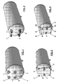
- a typical reservoir is usually provided with a side where there are pneumatic junctures for the input/output of the compressed air: in fig. 1 they are in central position 1, 2; in fig. 2 they are misaligned 3, 4 ( fig. 2 shows a misalignment in the lower part of the side, but other misalignment positions are possible); in fig. 14 they are in lateral position 5, 6.
- bosses 7 or through junctures 8 in addition to the pneumatic junctures 3, 4, that may be also used as fastening bosses.
- the bosses may be fixed directly to the frame, for example by means of screws, ( figures 6, 8 ), or by means of a plate 9 ( figures 3, 4 ).
- the plate is in its turn fixed, for example welded, to the frame ( figures 5, 7 ), by means of extensions, which may also engage directly with the side of the reservoir.
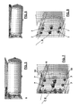
- the fixing system comprises joint guides, comprising a part fixed to the frame (elements 11, 12, 13) which engages with a part fixed to the side of the reservoir (elements 14, 15, 16).
- the two parts are equipped with joint rails with appropriate complementary shape.
- reservoirs equipped with lateral pneumatic junctures 5, 6, which do not interfere with the joint guides are preferable to use. These shapes allow to distribute the bending moment of the reservoir (which is projecting) on a wider supporting surface.
- An extension of the elements 11, 12, 13 is also possible in order to mount more than one reservoir.
Landscapes
- Engineering & Computer Science (AREA)
- Transportation (AREA)
- Mechanical Engineering (AREA)
- Valves And Accessory Devices For Braking Systems (AREA)
- Filling Or Discharging Of Gas Storage Vessels (AREA)
Abstract
Description
- The present invention refers to a fastening system for compressed air reservoir for industrial or commercial vehicle.
- Industrial or commercial vehicles are equipped with one or more compressed air reservoirs used for the activation of pneumatic devices.
- The reservoirs of the type known are generally formed by an elongated cylindrical tank and are fixed to the frame, in parallel or perpendicular position with respect to the side members, by means of a bracket that supports it and that is parallel to the reservoir itself, or by means of other types of supports that are also used to accommodate other elements such as batteries or other.
- Moreover there are also elastic bands, typically steel bands, that surround the reservoir and fasten it, possibly leaving a hollow space or using a rubber lining, in order to avoid sliding contacts which may provoke dangerous sparks near the reservoirs, and also in order to avoid scratches on the external surface of the reservoir which may rust.
- These tank support elements are bulky, heavy and expensive.
- Therefore the aim of the present invention is to provide a fastening system for compressed air reservoirs for industrial or commercial vehicle, that is light and cheap.
- The present invention relates to a fastening system for compressed air reservoirs for an industrial or commercial vehicle, said vehicle comprising a frame to which said reservoirs are fastened, said fastening system engaging with the frame, and only with the side of the tank facing the frame.
- The present invention relates in particular to a fastening system for compressed air reservoirs for industrial or commercial vehicles, as described more fully in the claims, which are an integral part of this description.
- Further purposes and advantages of the present invention will become clear from the following detailed description of a preferred embodiment (and relative alternative embodiments) and the drawings that are attached hereto, which are merely illustrative and not limitative, in which:
- figures from 1 to 14 show different embodiments of the fastening system for compressed air reservoirs according to the present invention.
- In the drawings the same reference numbers and letters are used to identify the same elements or components.
- According to the present invention the reservoir, which may be made of metal or of plastic, is fastened to the frame by means of a fastening system which engages only with the side of the reservoir facing the frame, so that all the other support elements of the type known described above may be removed.
- Different embodiments of the fastening system described below are possible.
- A typical reservoir is usually provided with a side where there are pneumatic junctures for the input/output of the compressed air: in
fig. 1 they are incentral position fig. 2 they are misaligned 3, 4 (fig. 2 shows a misalignment in the lower part of the side, but other misalignment positions are possible); infig. 14 they are in lateral position 5, 6. - On this side there are fastening
bosses 7 or throughjunctures 8 in addition to thepneumatic junctures
The bosses may be fixed directly to the frame, for example by means of screws, (figures 6, 8 ), or by means of a plate 9 (figures 3, 4 ). The plate is in its turn fixed, for example welded, to the frame (figures 5, 7 ), by means of extensions, which may also engage directly with the side of the reservoir. - According to further embodiments, shown in the figures from 9 to 13, the fixing system comprises joint guides, comprising a part fixed to the frame (
elements elements - In this case it is preferable to use reservoirs equipped with lateral pneumatic junctures 5, 6, which do not interfere with the joint guides.
These shapes allow to distribute the bending moment of the reservoir (which is projecting) on a wider supporting surface.
An extension of theelements - It will be apparent to the person skilled in the art that other alternative and equivalent embodiments of the invention can be conceived and reduced to practice without departing from the scope of the invention.
- From the description set forth above it will be possible for the person skilled in the art to embody the invention with no need of describing further construction details.
Claims (7)
- Fastening system for at least one compressed air reservoir for an industrial or commercial vehicle, said vehicle comprising a frame to which said reservoirs are fastened, said fastening system engaging with the frame, and only with the side of said at least one reservoir facing the frame.
- Fastening system according to claim 1, wherein said at least one reservoir comprises one side wherein there are pneumatic junctures for the input/output of the compressed air (1, 2, 3, 4, 5, 6), the fastening system comprising on said side fastening bosses (7) or through junctures (8) suitable for fixing said at least one reservoir directly to the frame.
- Fastening system according to claim 2, wherein said pneumatic junctures are part of the fastening system.
- Fastening system according to claim 2 or 3, further comprising a plate (9) between said fastening bosses (7) or through junctures (8) and said frame.
- Fastening system according to claim 4, wherein said plate is fixed to the frame by means of extensions (10), which engage also directly to said side of said at least one reservoir.
- Fastening system according to claim 1, wherein said at least one reservoir comprises one side wherein there are pneumatic junctures for the input/output of the compressed air (1, 2, 3, 4, 5, 6), the fastening system comprising on said side joint guides, comprising a first part fixed to the frame (11, 12, 13) which engages with the second part fixed to the side of said at least one reservoir (elements 14, 15, 16), said first and second part being equipped with joint rails.
- Fastening system according to claim 6, wherein said pneumatic junctures are in lateral position on said side.
Priority Applications (2)
| Application Number | Priority Date | Filing Date | Title |
|---|---|---|---|
| EP20080171772 EP2199167B1 (en) | 2008-12-16 | 2008-12-16 | Fastening system for compressed air reservoir for industrial or commercial vehicle |
| ES08171772T ES2399081T3 (en) | 2008-12-16 | 2008-12-16 | Clamping system for compressed air tank for industrial or commercial vehicle |
Applications Claiming Priority (1)
| Application Number | Priority Date | Filing Date | Title |
|---|---|---|---|
| EP20080171772 EP2199167B1 (en) | 2008-12-16 | 2008-12-16 | Fastening system for compressed air reservoir for industrial or commercial vehicle |
Publications (2)
| Publication Number | Publication Date |
|---|---|
| EP2199167A1 true EP2199167A1 (en) | 2010-06-23 |
| EP2199167B1 EP2199167B1 (en) | 2012-11-14 |
Family
ID=40636134
Family Applications (1)
| Application Number | Title | Priority Date | Filing Date |
|---|---|---|---|
| EP20080171772 Active EP2199167B1 (en) | 2008-12-16 | 2008-12-16 | Fastening system for compressed air reservoir for industrial or commercial vehicle |
Country Status (2)
| Country | Link |
|---|---|
| EP (1) | EP2199167B1 (en) |
| ES (1) | ES2399081T3 (en) |
Cited By (3)
| Publication number | Priority date | Publication date | Assignee | Title |
|---|---|---|---|---|
| EP2966332A1 (en) * | 2014-07-09 | 2016-01-13 | Iveco Magirus Ag | Drain valve for a pressurised fluid tank and pressurised fluid tank comprising the same |
| IT201700066784A1 (en) * | 2017-06-15 | 2018-12-15 | Iveco Magirus | STABLE CONNECTION SYSTEM OF A COMPRESSED OR HYDRAULIC OIL TANK WITH A VEHICLE FRAME |
| CN109466531A (en) * | 2017-09-08 | 2019-03-15 | 河南奔马股份有限公司 | A kind of vehicle and its gas receiver |
Citations (6)
| Publication number | Priority date | Publication date | Assignee | Title |
|---|---|---|---|---|
| JPH08282720A (en) * | 1995-04-19 | 1996-10-29 | Mitsubishi Automob Eng Co Ltd | Tank mounting device |
| DE29822006U1 (en) * | 1997-12-12 | 1999-04-15 | Linnemann-Schnetzer GmbH, 59229 Ahlen | Fastening device for pressure vessels |
| EP0926034A2 (en) * | 1997-12-15 | 1999-06-30 | Alutech Gesellschaft m.b.H. | Device for mounting compressed air reservoirs in a vehicle frame |
| DE102006010185A1 (en) * | 2006-03-06 | 2007-09-27 | Daimlerchrysler Ag | Fastening arrangement for e.g. compressed air container, has external attachment parts arranged in closed region of container at frame longitudinal support, where container is designed as holder, over which parts are fastened at support |
| DE102006043585A1 (en) * | 2006-09-16 | 2008-03-27 | Daimler Ag | Retaining arrangement for e.g. container, has cantilevers attached to mounting units and above which retainer is supported, and support carrier connected with support, where retainer is supported over support carrier |
| EP1970273A2 (en) | 2007-03-13 | 2008-09-17 | Alutech Gesellschaft m.b.H. | Attachment system for automobile containers |
-
2008
- 2008-12-16 EP EP20080171772 patent/EP2199167B1/en active Active
- 2008-12-16 ES ES08171772T patent/ES2399081T3/en active Active
Patent Citations (6)
| Publication number | Priority date | Publication date | Assignee | Title |
|---|---|---|---|---|
| JPH08282720A (en) * | 1995-04-19 | 1996-10-29 | Mitsubishi Automob Eng Co Ltd | Tank mounting device |
| DE29822006U1 (en) * | 1997-12-12 | 1999-04-15 | Linnemann-Schnetzer GmbH, 59229 Ahlen | Fastening device for pressure vessels |
| EP0926034A2 (en) * | 1997-12-15 | 1999-06-30 | Alutech Gesellschaft m.b.H. | Device for mounting compressed air reservoirs in a vehicle frame |
| DE102006010185A1 (en) * | 2006-03-06 | 2007-09-27 | Daimlerchrysler Ag | Fastening arrangement for e.g. compressed air container, has external attachment parts arranged in closed region of container at frame longitudinal support, where container is designed as holder, over which parts are fastened at support |
| DE102006043585A1 (en) * | 2006-09-16 | 2008-03-27 | Daimler Ag | Retaining arrangement for e.g. container, has cantilevers attached to mounting units and above which retainer is supported, and support carrier connected with support, where retainer is supported over support carrier |
| EP1970273A2 (en) | 2007-03-13 | 2008-09-17 | Alutech Gesellschaft m.b.H. | Attachment system for automobile containers |
Cited By (5)
| Publication number | Priority date | Publication date | Assignee | Title |
|---|---|---|---|---|
| EP2966332A1 (en) * | 2014-07-09 | 2016-01-13 | Iveco Magirus Ag | Drain valve for a pressurised fluid tank and pressurised fluid tank comprising the same |
| EP3379128A1 (en) * | 2014-07-09 | 2018-09-26 | Iveco Magirus Ag | Drain valve for a pressurised fluid tank and pressurised fluid tank comprising the same |
| IT201700066784A1 (en) * | 2017-06-15 | 2018-12-15 | Iveco Magirus | STABLE CONNECTION SYSTEM OF A COMPRESSED OR HYDRAULIC OIL TANK WITH A VEHICLE FRAME |
| EP3415387A1 (en) | 2017-06-15 | 2018-12-19 | Iveco Magirus Ag | System for stable connection of a reservoir for compressed air or hydraulic oil to a vehicle frame |
| CN109466531A (en) * | 2017-09-08 | 2019-03-15 | 河南奔马股份有限公司 | A kind of vehicle and its gas receiver |
Also Published As
| Publication number | Publication date |
|---|---|
| ES2399081T3 (en) | 2013-03-25 |
| EP2199167B1 (en) | 2012-11-14 |
Similar Documents
| Publication | Publication Date | Title |
|---|---|---|
| US8540262B2 (en) | Commercial vehicle and device for attaching a spring element to a commercial vehicle axle | |
| EP4155103B1 (en) | A system and a method for installation of traction batteries for a vehicle | |
| CN101910043B (en) | Electric vehicles, especially ground transport vehicles, with battery holders | |
| US9415650B2 (en) | Chassis control arm with an air-guiding device | |
| CN201590699U (en) | Motor support | |
| CA2626374A1 (en) | Removable chassis skirt | |
| EP2199167B1 (en) | Fastening system for compressed air reservoir for industrial or commercial vehicle | |
| US9034510B2 (en) | Battery pack and method of securing a plurality of battery modules in the battery pack | |
| KR200479787Y1 (en) | system strut u-head fixong apparatus | |
| CN202992383U (en) | Oil pipe support, oil pipe installation structure and vehicle | |
| MX2007000325A (en) | Low profile saddle mount. | |
| CN205800721U (en) | The carriage assembly of vehicle air conditioning pipeline, vehicle air conditioning assembly and vehicle | |
| CA2733490C (en) | Arrangement for supporting a subassembly on a motor vehicle body | |
| SE0702826L (en) | radiator bracket | |
| US9327573B2 (en) | Air spring attachment system | |
| ZA200804372B (en) | Device for mounting a weapon system on a vehicle chassis | |
| CN204367919U (en) | A kind of automobile side seat mounting bracket structure and automobile | |
| CN104203733A (en) | Fitting device for fitting drive assembly for vehicle | |
| CN112009226B (en) | Battery pack fixing device and electric automobile | |
| US20080142306A1 (en) | Industrial truck with a preassembled axle assembly | |
| CN110510007A (en) | Truck and car body guardrail | |
| US10556475B2 (en) | Stop device | |
| CN201474909U (en) | Novel engine air condition compressor bracket | |
| CN211592449U (en) | Protection device and vehicle with same | |
| CN218431083U (en) | Mounting structure and car of on-vehicle gas holder |
Legal Events
| Date | Code | Title | Description |
|---|---|---|---|
| PUAI | Public reference made under article 153(3) epc to a published international application that has entered the european phase |
Free format text: ORIGINAL CODE: 0009012 |
|
| AK | Designated contracting states |
Kind code of ref document: A1 Designated state(s): AT BE BG CH CY CZ DE DK EE ES FI FR GB GR HR HU IE IS IT LI LT LU LV MC MT NL NO PL PT RO SE SI SK TR |
|
| AX | Request for extension of the european patent |
Extension state: AL BA MK RS |
|
| 17P | Request for examination filed |
Effective date: 20100616 |
|
| AKX | Designation fees paid |
Designated state(s): AT BE BG CH CY CZ DE DK EE ES FI FR GB GR HR HU IE IS IT LI LT LU LV MC MT NL NO PL PT RO SE SI SK TR |
|
| GRAP | Despatch of communication of intention to grant a patent |
Free format text: ORIGINAL CODE: EPIDOSNIGR1 |
|
| RIN1 | Information on inventor provided before grant (corrected) |
Inventor name: DISTELRATH, HEINZ-PETER Inventor name: STUERNER, JOHANN Inventor name: POHL, HARALD Inventor name: NANDI, KIRON |
|
| GRAS | Grant fee paid |
Free format text: ORIGINAL CODE: EPIDOSNIGR3 |
|
| GRAA | (expected) grant |
Free format text: ORIGINAL CODE: 0009210 |
|
| AK | Designated contracting states |
Kind code of ref document: B1 Designated state(s): AT BE BG CH CY CZ DE DK EE ES FI FR GB GR HR HU IE IS IT LI LT LU LV MC MT NL NO PL PT RO SE SI SK TR |
|
| REG | Reference to a national code |
Ref country code: GB Ref legal event code: FG4D |
|
| REG | Reference to a national code |
Ref country code: AT Ref legal event code: REF Ref document number: 583807 Country of ref document: AT Kind code of ref document: T Effective date: 20121115 Ref country code: CH Ref legal event code: EP |
|
| REG | Reference to a national code |
Ref country code: IE Ref legal event code: FG4D |
|
| REG | Reference to a national code |
Ref country code: DE Ref legal event code: R096 Ref document number: 602008020080 Country of ref document: DE Effective date: 20130103 |
|
| REG | Reference to a national code |
Ref country code: SE Ref legal event code: TRGR |
|
| REG | Reference to a national code |
Ref country code: ES Ref legal event code: FG2A Ref document number: 2399081 Country of ref document: ES Kind code of ref document: T3 Effective date: 20130325 |
|
| REG | Reference to a national code |
Ref country code: NL Ref legal event code: T3 |
|
| REG | Reference to a national code |
Ref country code: AT Ref legal event code: MK05 Ref document number: 583807 Country of ref document: AT Kind code of ref document: T Effective date: 20121114 |
|
| REG | Reference to a national code |
Ref country code: LT Ref legal event code: MG4D |
|
| PG25 | Lapsed in a contracting state [announced via postgrant information from national office to epo] |
Ref country code: HR Free format text: LAPSE BECAUSE OF FAILURE TO SUBMIT A TRANSLATION OF THE DESCRIPTION OR TO PAY THE FEE WITHIN THE PRESCRIBED TIME-LIMIT Effective date: 20121114 Ref country code: LT Free format text: LAPSE BECAUSE OF FAILURE TO SUBMIT A TRANSLATION OF THE DESCRIPTION OR TO PAY THE FEE WITHIN THE PRESCRIBED TIME-LIMIT Effective date: 20121114 Ref country code: NO Free format text: LAPSE BECAUSE OF FAILURE TO SUBMIT A TRANSLATION OF THE DESCRIPTION OR TO PAY THE FEE WITHIN THE PRESCRIBED TIME-LIMIT Effective date: 20130214 Ref country code: FI Free format text: LAPSE BECAUSE OF FAILURE TO SUBMIT A TRANSLATION OF THE DESCRIPTION OR TO PAY THE FEE WITHIN THE PRESCRIBED TIME-LIMIT Effective date: 20121114 |
|
| PG25 | Lapsed in a contracting state [announced via postgrant information from national office to epo] |
Ref country code: GR Free format text: LAPSE BECAUSE OF FAILURE TO SUBMIT A TRANSLATION OF THE DESCRIPTION OR TO PAY THE FEE WITHIN THE PRESCRIBED TIME-LIMIT Effective date: 20130215 Ref country code: BE Free format text: LAPSE BECAUSE OF FAILURE TO SUBMIT A TRANSLATION OF THE DESCRIPTION OR TO PAY THE FEE WITHIN THE PRESCRIBED TIME-LIMIT Effective date: 20121114 Ref country code: LV Free format text: LAPSE BECAUSE OF FAILURE TO SUBMIT A TRANSLATION OF THE DESCRIPTION OR TO PAY THE FEE WITHIN THE PRESCRIBED TIME-LIMIT Effective date: 20121114 Ref country code: SI Free format text: LAPSE BECAUSE OF FAILURE TO SUBMIT A TRANSLATION OF THE DESCRIPTION OR TO PAY THE FEE WITHIN THE PRESCRIBED TIME-LIMIT Effective date: 20121114 Ref country code: PL Free format text: LAPSE BECAUSE OF FAILURE TO SUBMIT A TRANSLATION OF THE DESCRIPTION OR TO PAY THE FEE WITHIN THE PRESCRIBED TIME-LIMIT Effective date: 20121114 Ref country code: PT Free format text: LAPSE BECAUSE OF FAILURE TO SUBMIT A TRANSLATION OF THE DESCRIPTION OR TO PAY THE FEE WITHIN THE PRESCRIBED TIME-LIMIT Effective date: 20130314 |
|
| PG25 | Lapsed in a contracting state [announced via postgrant information from national office to epo] |
Ref country code: AT Free format text: LAPSE BECAUSE OF FAILURE TO SUBMIT A TRANSLATION OF THE DESCRIPTION OR TO PAY THE FEE WITHIN THE PRESCRIBED TIME-LIMIT Effective date: 20121114 |
|
| PG25 | Lapsed in a contracting state [announced via postgrant information from national office to epo] |
Ref country code: DK Free format text: LAPSE BECAUSE OF FAILURE TO SUBMIT A TRANSLATION OF THE DESCRIPTION OR TO PAY THE FEE WITHIN THE PRESCRIBED TIME-LIMIT Effective date: 20121114 Ref country code: CZ Free format text: LAPSE BECAUSE OF FAILURE TO SUBMIT A TRANSLATION OF THE DESCRIPTION OR TO PAY THE FEE WITHIN THE PRESCRIBED TIME-LIMIT Effective date: 20121114 Ref country code: BG Free format text: LAPSE BECAUSE OF FAILURE TO SUBMIT A TRANSLATION OF THE DESCRIPTION OR TO PAY THE FEE WITHIN THE PRESCRIBED TIME-LIMIT Effective date: 20130214 Ref country code: EE Free format text: LAPSE BECAUSE OF FAILURE TO SUBMIT A TRANSLATION OF THE DESCRIPTION OR TO PAY THE FEE WITHIN THE PRESCRIBED TIME-LIMIT Effective date: 20121114 Ref country code: SK Free format text: LAPSE BECAUSE OF FAILURE TO SUBMIT A TRANSLATION OF THE DESCRIPTION OR TO PAY THE FEE WITHIN THE PRESCRIBED TIME-LIMIT Effective date: 20121114 Ref country code: MC Free format text: LAPSE BECAUSE OF NON-PAYMENT OF DUE FEES Effective date: 20121231 |
|
| REG | Reference to a national code |
Ref country code: CH Ref legal event code: PL |
|
| PG25 | Lapsed in a contracting state [announced via postgrant information from national office to epo] |
Ref country code: RO Free format text: LAPSE BECAUSE OF FAILURE TO SUBMIT A TRANSLATION OF THE DESCRIPTION OR TO PAY THE FEE WITHIN THE PRESCRIBED TIME-LIMIT Effective date: 20121114 |
|
| PLBE | No opposition filed within time limit |
Free format text: ORIGINAL CODE: 0009261 |
|
| STAA | Information on the status of an ep patent application or granted ep patent |
Free format text: STATUS: NO OPPOSITION FILED WITHIN TIME LIMIT |
|
| REG | Reference to a national code |
Ref country code: IE Ref legal event code: MM4A |
|
| 26N | No opposition filed |
Effective date: 20130815 |
|
| PG25 | Lapsed in a contracting state [announced via postgrant information from national office to epo] |
Ref country code: LI Free format text: LAPSE BECAUSE OF NON-PAYMENT OF DUE FEES Effective date: 20121231 Ref country code: IE Free format text: LAPSE BECAUSE OF NON-PAYMENT OF DUE FEES Effective date: 20121216 Ref country code: CH Free format text: LAPSE BECAUSE OF NON-PAYMENT OF DUE FEES Effective date: 20121231 |
|
| PG25 | Lapsed in a contracting state [announced via postgrant information from national office to epo] |
Ref country code: CY Free format text: LAPSE BECAUSE OF FAILURE TO SUBMIT A TRANSLATION OF THE DESCRIPTION OR TO PAY THE FEE WITHIN THE PRESCRIBED TIME-LIMIT Effective date: 20121114 Ref country code: MT Free format text: LAPSE BECAUSE OF FAILURE TO SUBMIT A TRANSLATION OF THE DESCRIPTION OR TO PAY THE FEE WITHIN THE PRESCRIBED TIME-LIMIT Effective date: 20121114 |
|
| REG | Reference to a national code |
Ref country code: DE Ref legal event code: R097 Ref document number: 602008020080 Country of ref document: DE Effective date: 20130815 |
|
| PG25 | Lapsed in a contracting state [announced via postgrant information from national office to epo] |
Ref country code: TR Free format text: LAPSE BECAUSE OF FAILURE TO SUBMIT A TRANSLATION OF THE DESCRIPTION OR TO PAY THE FEE WITHIN THE PRESCRIBED TIME-LIMIT Effective date: 20121114 |
|
| PG25 | Lapsed in a contracting state [announced via postgrant information from national office to epo] |
Ref country code: LU Free format text: LAPSE BECAUSE OF NON-PAYMENT OF DUE FEES Effective date: 20121216 |
|
| PG25 | Lapsed in a contracting state [announced via postgrant information from national office to epo] |
Ref country code: HU Free format text: LAPSE BECAUSE OF FAILURE TO SUBMIT A TRANSLATION OF THE DESCRIPTION OR TO PAY THE FEE WITHIN THE PRESCRIBED TIME-LIMIT Effective date: 20081216 |
|
| REG | Reference to a national code |
Ref country code: FR Ref legal event code: PLFP Year of fee payment: 8 |
|
| PG25 | Lapsed in a contracting state [announced via postgrant information from national office to epo] |
Ref country code: IS Free format text: LAPSE BECAUSE OF FAILURE TO SUBMIT A TRANSLATION OF THE DESCRIPTION OR TO PAY THE FEE WITHIN THE PRESCRIBED TIME-LIMIT Effective date: 20121114 |
|
| REG | Reference to a national code |
Ref country code: FR Ref legal event code: PLFP Year of fee payment: 9 |
|
| REG | Reference to a national code |
Ref country code: FR Ref legal event code: PLFP Year of fee payment: 10 |
|
| P01 | Opt-out of the competence of the unified patent court (upc) registered |
Effective date: 20230522 |
|
| PGFP | Annual fee paid to national office [announced via postgrant information from national office to epo] |
Ref country code: GB Payment date: 20251223 Year of fee payment: 18 |
|
| PGFP | Annual fee paid to national office [announced via postgrant information from national office to epo] |
Ref country code: IT Payment date: 20251118 Year of fee payment: 18 |
|
| PGFP | Annual fee paid to national office [announced via postgrant information from national office to epo] |
Ref country code: NL Payment date: 20251222 Year of fee payment: 18 Ref country code: FR Payment date: 20251223 Year of fee payment: 18 |
|
| PGFP | Annual fee paid to national office [announced via postgrant information from national office to epo] |
Ref country code: SE Payment date: 20251222 Year of fee payment: 18 |
|
| PGFP | Annual fee paid to national office [announced via postgrant information from national office to epo] |
Ref country code: ES Payment date: 20260122 Year of fee payment: 18 |
|
| PGFP | Annual fee paid to national office [announced via postgrant information from national office to epo] |
Ref country code: DE Payment date: 20251229 Year of fee payment: 18 |