EP2198663B1 - Uplink scheduling grant for time division duplex with asymmetric uplink and downlink configuration - Google Patents
Uplink scheduling grant for time division duplex with asymmetric uplink and downlink configuration Download PDFInfo
- Publication number
- EP2198663B1 EP2198663B1 EP08807322.6A EP08807322A EP2198663B1 EP 2198663 B1 EP2198663 B1 EP 2198663B1 EP 08807322 A EP08807322 A EP 08807322A EP 2198663 B1 EP2198663 B1 EP 2198663B1
- Authority
- EP
- European Patent Office
- Prior art keywords
- subframes
- scheduling grant
- uplink
- downlink
- subframe
- Prior art date
- Legal status (The legal status is an assumption and is not a legal conclusion. Google has not performed a legal analysis and makes no representation as to the accuracy of the status listed.)
- Active
Links
- 238000013507 mapping Methods 0.000 claims description 22
- 230000005540 biological transmission Effects 0.000 claims description 21
- 238000000034 method Methods 0.000 claims description 18
- 208000037918 transfusion-transmitted disease Diseases 0.000 description 60
- 230000011664 signaling Effects 0.000 description 15
- 238000004891 communication Methods 0.000 description 9
- 238000013461 design Methods 0.000 description 9
- 238000010586 diagram Methods 0.000 description 7
- 239000004065 semiconductor Substances 0.000 description 6
- 238000001514 detection method Methods 0.000 description 5
- 238000012545 processing Methods 0.000 description 5
- 238000013468 resource allocation Methods 0.000 description 5
- 230000006870 function Effects 0.000 description 4
- 238000012986 modification Methods 0.000 description 4
- 230000004048 modification Effects 0.000 description 4
- 238000013459 approach Methods 0.000 description 3
- 101150069124 RAN1 gene Proteins 0.000 description 2
- 101100355633 Salmo salar ran gene Proteins 0.000 description 2
- 230000006978 adaptation Effects 0.000 description 2
- 230000008901 benefit Effects 0.000 description 2
- 238000005516 engineering process Methods 0.000 description 2
- 230000007774 longterm Effects 0.000 description 2
- 238000004519 manufacturing process Methods 0.000 description 2
- 230000008569 process Effects 0.000 description 2
- 230000002457 bidirectional effect Effects 0.000 description 1
- 238000004364 calculation method Methods 0.000 description 1
- 239000000969 carrier Substances 0.000 description 1
- 230000001413 cellular effect Effects 0.000 description 1
- 239000004020 conductor Substances 0.000 description 1
- 230000008878 coupling Effects 0.000 description 1
- 238000010168 coupling process Methods 0.000 description 1
- 238000005859 coupling reaction Methods 0.000 description 1
- 238000013500 data storage Methods 0.000 description 1
- 230000001934 delay Effects 0.000 description 1
- 230000001419 dependent effect Effects 0.000 description 1
- 230000003287 optical effect Effects 0.000 description 1
- 230000003068 static effect Effects 0.000 description 1
- 239000000758 substrate Substances 0.000 description 1
- 230000036962 time dependent Effects 0.000 description 1
Images


Classifications
-
- H—ELECTRICITY
- H04—ELECTRIC COMMUNICATION TECHNIQUE
- H04W—WIRELESS COMMUNICATION NETWORKS
- H04W72/00—Local resource management
- H04W72/20—Control channels or signalling for resource management
- H04W72/23—Control channels or signalling for resource management in the downlink direction of a wireless link, i.e. towards a terminal
-
- H—ELECTRICITY
- H04—ELECTRIC COMMUNICATION TECHNIQUE
- H04W—WIRELESS COMMUNICATION NETWORKS
- H04W72/00—Local resource management
- H04W72/04—Wireless resource allocation
- H04W72/044—Wireless resource allocation based on the type of the allocated resource
- H04W72/0446—Resources in time domain, e.g. slots or frames
Definitions
- the teachings herein relate generally to wireless networks that allocate uplink and downlink resources to mobile equipment, particularly where the allocation is or may be asymmetric as between the uplink and downlink subframe resources being allocated.
- 3GPP is standardizing the long-term evolution (LTE) of the radio-access technology which aims to achieve reduced latency, higher user data rates, improved system capacity and coverage, and reduced cost for the operator.
- LTE long-term evolution
- TR 25.814 v7.1.0, 2006-09
- PHYSICAL LAYER ASPECTS OF EVOLVED UTRA Both FDD and TDD are considered in LTE. Due to their difference in frame structure and duplex mode, some designs for FDD and TDD can be different (see section 6.2 et seq. of TR 25.814).
- E-UTRA when operating in TDD mode-of-operation, may face additional interference scenarios, compared to when operating in FDD mode of operation. More specifically, direct UE-to-UE and BS-to-BS interference may occur both within one carrier and between neighbour carriers.” As LTE develops it is clear that there are to be some differences as between the FDD and TDD modes of operation.
- the Node B scheduler dynamically controls which time/frequency resources, such as subframes, are allocated to a certain user at a given time. Downlink control signalling informs UE(s) what resources/subframes and respective transmission formats have been allocated. The scheduler can instantaneously choose the best multiplexing strategy from the available methods; e.g. frequency localized or frequency distributed transmission. The flexibility in selecting subframes and multiplexing UEs will influence the available scheduling performance. Scheduling is tightly integrated with link adaptation and hybrid automatic repeat request HARQ.
- a TTI is one subframe.
- Those 3 OFDM symbols are to include DL and UL scheduling grants as well as CCFI/Cat0 information that gives the format of the control channel.
- the CCFI/Cat0 is length 2 bits and indicates how many OFDM symbols are used for control (see page 12 of document RP-070271, STATUS REPORT RAN WG1 TO TSG-RAN #36; Busan, Korea; 28 May-1 June 2007).
- the size of the DL control resource limits the number of UEs that can be scheduled.
- a rough calculation shows that if 3 OFDM symbols are reserved for control in each DL subframe, there are 8DL and 7UL UEs can be scheduled per TTI in a system having a 10msec radio frame as in LTE.
- the DL and UL configuration can be asymmetric, more limitations exist in the scheduling and so the 8DL/7UL limit may not be attainable in certain instances due to the asymmetry that may be present.
- This invention addresses some of those problems in TDD UL scheduling, which by the above framework must be done in conjunction with the DL scheduling.
- LTE Long Term Evolution
- frame structure 1 FS1 and frame structure 2 FS2 The TDD mode of LTE may have asymmetric DL and UL subframe allocation for both FS1 and FS2.
- TDD FS2 with 6DL subframes and 1UL subframe being allocated in a 5msec frame.
- One option is to constraint the UL scheduling grant for the UL subframe in the first DL subframe.
- Another option is to allow the UL scheduling grant for the UL subframe in more than the first DL subframe. And that choice must also enable one to send the UL scheduling grant for a TDD FS2 with an opposite symmetry, for example scheduling 5UL subframes and 2 DL subframes. The mapping becomes quite difficult, especially considering the limits on scheduling overhead already agreed in LTE.
- the present invention is defined by means of a method and an associated apparatus in accordance with independent claims 1 and 7. It is also defined by means of a method and an associated apparatus in accordance with independent claims 12 and 13. Preferred embodiments are defined in dependent claims.
- Embodiments of this invention relate to asymmetry in both directions, where there is a greater number of DL than UL subframes allocated/scheduled, and also where there is a greater number of UL than DL subframes allocated/scheduled.
- the scheduling grants for the UL subframes occurs within the DL subframes.
- the discussion below is in terms of scheduling grants for subframes/timeslots within a frame where the scheduled TDD resources/subframes are consecutive.
- the Node B scheduler will create or follow a mapping between the DL subframes and the UL subframes, since control signalling for the scheduling grants are in the DL subframes but they schedule also the UL subframes. Implicit mapping is seen to be too inflexible and as seen above in the background section, entails quite a bit of signaling overhead and complexity when more UL subframes are allocated than DL subframes.
- a TTI indicator in the resource grant maps explicitly to the granted UL subframe.
- the UL subframes are grouped, so the TTI indicator in one scheduling grant will map to more than one UL subframe of the overall frame.
- the number of groups into which all of the scheduled UL subframes are divided is equal to the number of DL subframes being scheduled in that same TTI, so the number of groups equals the number of DL subframes in the frame. So in this first aspect the UL subframes are divided into N groups, where N is the number of DL subframes, and the scheduling grant for the ith group is in the ith DL subframe. This is advantageous when the number of UL subframes is greater than the number of DL subframes in the frame.
- a second aspect of the invention there is a one-to-one mapping between grant and UL subframe, but the coupling between DL and UL grants that was detailed above in the background section is dissolved.
- there is a logical channel defined for a UL subframe and scheduling grants given on that logical channel are grants for the UL subframe associated with that logical channel.
- the control signaling resource for the UL subframes is divided into M parts, where each part is a logical control channel for UL scheduling grants and where M is the number of UL subframes in the frame. Then, the scheduling grant for the ith UL subframe is sent in the ith logical control channel, and this applies for any ratio of DL to UL subframe.
- a first option is an implicit one-to-one mapping between DL subframe in which a UL scheduling grant is received and UL subframe being allocated so that a UL scheduling grant on an ith DL subframe maps to an ith UL subframe.
- a second option is to allow the UL scheduling grant for one UL TTI to be indicated in more than one DL subframe, and use an explicit TTI indication in the UL scheduling grant only when necessary.
- a novel arrangement or pattern of the CCFI/Cat0 bits is exploited to indicate whether or not there is a UL scheduling grant in the ith DL subframe. This enables the UEs being scheduled to avoid blind detection, looking for their scheduling grant that is not there.
- the explicit TTI indication can be used to tell that the scheduling grant is for which UL subframe.
- TTI indication that maps the UL scheduling grant explicitly to a UL subframe. While this may be done by implicit mapping, this is seen to lack flexibility to a degree that makes it less favored than other approaches. Most simply, a sufficiently long TTI indication would assure that any number of UL subframes could be mapped.
- TTI index For example, three bits are sufficient for this TTI index is using single TTI scheduling. Five bits would be sufficient for this TTI index if multi-TTI scheduling is allowed in the TDD FS2 (with 2DL and 5 UL subframes). However many bits, there are a different number of bits indicating single TTI scheduling versus multi-TTI scheduling.
- the explicit TTI mapping for the case where DL ⁇ UL becomes costly in terms of bandwidth becomes costly in terms of bandwidth.
- the UL subframes are divided into groups, say N groups where N is an integer equal to the number of DL subframes in the TDD frame. Because in this instance DL ⁇ UL, then at least one of the N groups must include more than one of the UL subframes.
- the scheduling grant for the UL subframes in the ith group is sent in the ith DL subframe. Then in each UL scheduling grant the TTI indication is shortened as compared to the 3 or 5 bits noted above. As will be detailed below, in some DL subframes the TTI indication can even be avoided altogether.
- This first aspect of the invention is shown by example at Figure 2-3 and 6 for various configurations of DL and UL subframes being scheduled in FS2 and FS1.
- a TDD FS2 with three DL subframes being scheduled, designated as 201, 202 and 203, and four UL subframes being scheduled, designated as 210, 211, 212 and 213.
- the DL subframes 201, 202 and 203 are scheduled in the DL scheduling grants 201A, 202A and 203A.
- the first and second groups have one UL subframe and the third group has two UL subframes.
- the first UL scheduling grant 202B schedules UEs for the first UL subframe 210.
- the second UL scheduling grant 203B schedules UEs for the second UL subframe 211.
- the third UL scheduling grant 204B schedules UEs for the third group of UL subframes, which include both subframe 212 and 213.
- no TTI indication is needed since there will be a one-to-one correspondence and implicit mapping when there is only one UL subframe in a particular group.
- the TTI indication is present and its bit length is one for the case of single TTI scheduling as shown, or it may be length two for the case where multi-TTI scheduling is allowed (a grant in one TTI grants resources in more than one TTI).
- Figure 3 shows an example of TDD FS2 with two DL subframes, designated 301 and 302 and scheduled by the DL grants 301A and 302A respectively, and five UL subframes designated as 310 through 314 scheduled by the UL grants 302B and 303B.
- the first group includes the first two UL subframes 310 and 311, and is scheduled by the UL grant 302B.
- the second group includes the remaining three UL subframes 312, 313 and 314.
- the TTI indication length can be as little as one bit in the first UL scheduling grant 302B, and as little as two bits in the second UL scheduling grant 303B. If multi-TTI scheduling grant is supported, the TTI indications may then be a minimum of two and three bits respectively for those grants 302B, 303B.
- TTI bit sequences and their meanings are shown below for the case where the network allows multi-TTI scheduling.
- the first group is UL subframes 610 and 611; the second group is UL subframe 612 only; and the third group is UL subframes 613 through 615.
- the first group is scheduled by the UL scheduling grant 601 B sent in the first DL subframe 601; the second group is scheduled by the UL scheduling grant 602B sent in the second DL subframe 602, and the third group is scheduled by the UL scheduling grant 603B sent in the third DL subframe 603.
- the length of the TTI indication for the scheduling grants of the first two groups is as little as two (since the first group has two UL subframes) and the length of the TTI indication for the third group is as little as three.
- directly indicating the UL resource being allocated in a TTI indicator would require the maximum TTI indication length to be seven.
- Figure 8 shows exemplary method steps for the first aspect of the invention detailed by example above.
- the Node B allocates a number N of DL subframes within a TDD frame for the downlink and a greater number >N of subframes within the TDD frame as uplink resources. Nothing yet is signalled or scheduled.
- the Node B then divides/groups the (more than N) UL subframes into only N groups, so necessarily there must be more than one UL subframe in at least one of those N groups (N is an integer).
- the Node B transmits its scheduling grants, denoted in Figure 8 as N grant messages. Each of those N grant messages schedules one of the DL subframes.
- each of those same N grant messages also schedules one of the groups of UL subframes.
- an indicator such as the TTI indicators noted above that indicate to the UE(s) which one(s) of the UL subframes are in the group being scheduled.
- the paradigm noted in the background section is changed so that the downlink scheduling information is decoupled from the uplink control information.
- one logical UL scheduling grant channel is associated with each UL subframe.
- One of those logical UL scheduling grant channels is mapped to some physical subframes within the over all OFDM symbols conveying the scheduling information. Note that this is a one-to-one mapping between a UL sub frame and a logical UL scheduling grant channel.
- An advantage of this third option is there is no explicit time information needed in the scheduling grant itself. There may however be an added limit on the Node B scheduler by the predefined implicit mapping, as this is not seen to be quite as flexible as the second option noted above with the explicit mapping and the avoidance of blind detection by use of the new Cat0 bit sequence.
- Figure 4 shows an example of this second aspect of the invention, for TDD FS2 with two DL subframes designated 401 and 402, and five UL subframes designated 410 through 414.
- Each of these UL scheduling grant channels are predefined and each is associated with one UL subframe, so for example if a UE receives a UL scheduling grant on channel 413A, it knows from the association stored in its memory that it is a UL grant for the fifth subframe in the frame.
- that fifth subframe is designated 413.
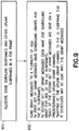
- This second aspect of the invention is shown at Figure 9 as process or method steps.
- the Node B allocates some subframes in a TDD frame as downlink subframes and others of the subframes as uplink subframes.
- the Node B sends grant messages scheduling the UEs according to the UL or DL allocation.
- those grant messages as being a first set and a second set of grant messages, mutually exclusive of one another.
- the first set of the grant messages includes the scheduling grants for the downlink subframes.
- Each grant message in the second set of grant messages includes a scheduling grant for one and only one of the UL subframes.
- the grant messages of the second set are sent over the pre-determined logical UL scheduling grant channels, one scheduling grant (and hence one UL subframe) per UL scheduling grant channel.
- the mapping as to this one-to-one correspondence may be sent with the grant messages themselves, or it may be relatively static (e.g., channel A corresponds to first subframe in the frame, channel B to the second, etc. with the Node B choosing frame by frame which if any of those subframes will be used for UL or DL) and broadcast on a broadcast channel at much less frequent intervals, such as with system information.
- the UL scheduling grant for the ith UL subframe is sent in the ith DL subframe.
- the advantage of this first option is that there is an implicit mapping and no TTI indication in the UL scheduling grant is needed, so the control signaling overhead is quite minimal-just sending the implicit mapping in current use to the UEs.
- This is advantageously done sometime when the particular UE is in the Node B's cell, such as sending the mapping over a broadcast channel whereby the UE stores the mapping and accesses it anytime it receives a scheduling grant.
- the number of UEs that can be scheduled is limited by the size of the control resource in the ith DL subframe. In systems with many VOIP UEs, it is preferable that the Node B be able to schedule a large number of UEs to support the retransmission of VOIP.
- scheduling of the UL subframes is not restricted to map to any particular DL subframe and can instead be given in any of the DL subframes.
- this second option instead there is a TTI indication in the UL scheduling grant.
- the CCFI/Cat0 bit field is enhanced as compared to current practice with a new bit sequence that shows whether there is UL subframe scheduling in the ith DL subframe. When that bit sequence shows there is no UL subframe scheduled, then the UE need not engage in detection.
- This second option encompasses additional flexibility over the first option in that the UL scheduling grant can occur in any of the DL subframes.
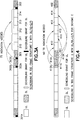
- FIG. 1 This second option is shown in the signalling diagrams of Figures 1 and 5 , Figure 1 showing an example for TDD FS2 and Figure 5 showing an example for TDD FS1.
- the legend in Figure 1 applies also to Figures 2-6 .
- the example of Figure 1 has six DL subframes, designated 101 through 106 and scheduled by the respective DL scheduling grants 101A through 106A, and one UL subframe, designated 110 and scheduled by the UL scheduling grants 102B, 103B and 104B.
- the scheduling grant for the UL subframe 110 is sent in the first three DL subframes 102', 103' and 104' following the last scheduled UL subframe 110'.
- the scheduling grant for the single UL subframe 110 is spread among three DL subframes.
- Figure 5 shows this second option in a TDD FS1 format, where there are eight DL subframes, designated 501 through 508, and 2 UL subframes, designated 510 and 511, being scheduled.
- the subframes in FS1 are generally referred to as timeslots and in FS2 as subframes.
- Figure 5 shows that the scheduling grant for the two UL subframes 510, 511 can be sent by the Node B in more than two DL subframes.
- the scheduling grant 502B and 503B for the first UL subframe 510 is spread among two DL subframes 502 and 503.
- the scheduling grant 506B and 507B for the second of the UL subframes 511 is spread among DL subframes 506 and 507.
- the TTI indicator in those UL scheduling grants 502B, 503B, 506B, 507B maps explicitly to the scheduled UL subframe.
- the Cat0 bit sequence enables the UE to avoid blind detection where no UL grant is sent.
- Figure 3B which uses the same TDD frame as in Figure 3A but assumes a three subframe processing delay. Reference numbers in Figure 3B are primed as compared to Figure 3A , and there are three subframes in the first group and two subframes in the second group as opposed to the two followed by three subframe groupings of Figure 3A .
- Uplink scheduling grant 302B' is for UL subframes 310', 311' and 312'
- uplink scheduling grant 303B' is for subframes 313' and 314' in Figure 3B .
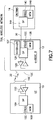
- a wireless network 708 is adapted for communication between a UE 10 and a Node B 12 (e-Node B).
- the network 708 may include a gateway GW/serving mobility entity MME/radio network controller RNC 14 or other radio controller function known by various terms in different wireless communication systems.
- the UE 10 includes a data processor (DP) 10A, a memory (MEM) 10B that stores a program (PROG) 10C, and a suitable radio frequency (RF) transceiver 10D coupled to one or more antennas 10E (one shown) for bidirectional wireless communications over one or more wireless links 20 with the Node B 12.
- DP data processor
- MEM memory
- PROG program
- RF radio frequency
- the Node B 12 also includes a DP 12A, a MEM 12B, that stores a PROG 12C, and a suitable RF transceiver 12D coupled to one or more antennas 12E.
- the Node B 12 may be coupled via a data path 30 (e.g., lub or S1 interface) to the serving or other GW/MME/RNC 14.
- the GW/MME/RNC 14 includes a DP 14A, a MEM 14B that stores a PROG 14C, and a suitable modem and/or transceiver (not shown) for communication with the Node B 12 over the lub link 30.
- a scheduler 12F that schedule the various UEs under its control for the various UL and DL subframes. Once scheduled, the Node B sends messages to the UEs with the scheduling grants (typically multiplexing grants for multiple UEs in one message). These grants are sent over the particular channels noted with the specific embodiments detailed above.
- the Node B 12 of an LTE system is fairly autonomous in its scheduling and need not coordinate with the GW/MME 14 excepting during handover of one of its UEs to another Node B.
- At least one of the PROGs 10C, 12C and 14C is assumed to include program instructions that, when executed by the associated DP, enable the electronic device to operate in accordance with the exemplary embodiments of this invention, as detailed above.
- Inherent in the DPs 10A, 12A, and 214A is a clock to enable synchronism among the various apparatus for transmissions and receptions within the appropriate time intervals and slots required, as the scheduling grants and the granted resources/subframes are time dependent.
- the PROGs 10C, 12C, 14C may be embodied in software, firmware and/or hardware, as is appropriate.
- the exemplary embodiments of this invention may be implemented by computer software stored in the MEM 10B and executable by the DP 10A of the UE 10 and similar for the other MEM 12B and DP 12A of the Node B 12, or by hardware, or by a combination of software and/or firmware and hardware in any or all of the devices shown.
- the various embodiments of the UE 10 can include, but are not limited to, mobile stations, cellular telephones, personal digital assistants (PDAs) having wireless communication capabilities, portable computers having wireless communication capabilities, image capture devices such as digital cameras having wireless communication capabilities, gaming devices having wireless communication capabilities, music storage and playback appliances having wireless communication capabilities, Internet appliances permitting wireless Internet access and browsing, as well as portable units or terminals that incorporate combinations of such functions.
- PDAs personal digital assistants
- portable computers having wireless communication capabilities
- image capture devices such as digital cameras having wireless communication capabilities
- gaming devices having wireless communication capabilities
- music storage and playback appliances having wireless communication capabilities
- Internet appliances permitting wireless Internet access and browsing, as well as portable units or terminals that incorporate combinations of such functions.
- the MEMs 10B, 12B and 14B may be of any type suitable to the local technical environment and may be implemented using any suitable data storage technology, such as semiconductor-based memory devices, magnetic memory devices and systems, optical memory devices and systems, fixed memory and removable memory.
- the DPs 10A, 12A and 14A may be of any type suitable to the local technical environment, and may include one or more of general purpose computers, special purpose computers, microprocessors, digital signal processors (DSPs) and processors based on a multi-core processor architecture, as non-limiting examples.
- embodiments of this invention may be implemented by computer software executable by a data processor of the Node B 12, such as the processor 12A shown, or by hardware, or by a combination of software and hardware.
- embodiments of this invention may be implemented by computer software executable by a data processor of the UE 10, such as the processor 10A shown, or by hardware, or by a combination of software and hardware.
- the various logical step descriptions above may represent program steps, or interconnected logic circuits, blocks and functions, or a combination of program steps and logic circuits, blocks and functions.
- the various embodiments may be implemented in hardware or special purpose circuits, software (computer readable instructions embodied on a computer readable medium), logic or any combination thereof.
- some aspects may be implemented in hardware, while other aspects may be implemented in firmware or software which may be executed by a controller, microprocessor or other computing device, although the invention is not limited thereto.
- firmware or software which may be executed by a controller, microprocessor or other computing device, although the invention is not limited thereto.
- While various aspects of the invention may be illustrated and described as block diagrams, flow charts, or using some other pictorial representation, it is well understood that these blocks, apparatus, systems, techniques or methods described herein may be implemented in, as non-limiting examples, hardware, software, firmware, special purpose circuits or logic, general purpose hardware or controller or other computing devices, or some combination thereof.
- Embodiments of the inventions may be practiced in various components such as integrated circuit modules.
- the design of integrated circuits is by and large a highly automated process.
- Complex and powerful software tools are available for converting a logic level design into a semiconductor circuit design ready to be etched and formed on a semiconductor substrate.
- Programs such as those provided by Synopsys, Inc. of Mountain View, California and Cadence Design, of San Jose, California automatically route conductors and locate components on a semiconductor chip using well established rules of design as well as libraries of pre-stored design modules.
- the resultant design in a standardized electronic format (e.g., Opus, GDSII, or the like) may be transmitted to a semiconductor fabrication facility or "fab" for fabrication.
Landscapes
- Engineering & Computer Science (AREA)
- Computer Networks & Wireless Communication (AREA)
- Signal Processing (AREA)
- Mobile Radio Communication Systems (AREA)
Description
- The teachings herein relate generally to wireless networks that allocate uplink and downlink resources to mobile equipment, particularly where the allocation is or may be asymmetric as between the uplink and downlink subframe resources being allocated.
- The following abbreviations and terms are herewith defined:
- 3GPP
- third generation partnership project
- CCFI
- control channel format indicator (alternatively Cat0)
- DL:
- downlink
- Node B
- base station, or evolved node B of an LTE system
- E-UTRAN
- evolved UTRAN
- FDD:
- frequency division duplex
- FS1:
- frame structure 1
- FS2:
-
frame structure 2 - LTE
- long term evolution of 3GPP
- MCS
- modulation and coding scheme
- Node B
- base station or similar network access node
- OFDM
- orthogonal frequency division multiplex
- TDD
- time division duplex
- UE
- user equipment (e.g., mobile equipment/station)
- UL
- uplink
- UMTS
- universal mobile telecommunications system
- UTRAN
- UMTS terrestrial radio access network
- VOIP
- voice over Internet protocol IP
- 3GPP is standardizing the long-term evolution (LTE) of the radio-access technology which aims to achieve reduced latency, higher user data rates, improved system capacity and coverage, and reduced cost for the operator. The current understanding of LTE relevant to these teachings may be seen at 3GPP TR 25.814 (v7.1.0, 2006-09) entitled PHYSICAL LAYER ASPECTS OF EVOLVED UTRA. Both FDD and TDD are considered in LTE. Due to their difference in frame structure and duplex mode, some designs for FDD and TDD can be different (see section 6.2 et seq. of TR 25.814). As stated at section 6.2.1, "E-UTRA, when operating in TDD mode-of-operation, may face additional interference scenarios, compared to when operating in FDD mode of operation. More specifically, direct UE-to-UE and BS-to-BS interference may occur both within one carrier and between neighbour carriers." As LTE develops it is clear that there are to be some differences as between the FDD and TDD modes of operation.
- Some general principles of scheduling in E-UTRAN are recited at section 7.2.1 of TR 25.814. The Node B scheduler dynamically controls which time/frequency resources, such as subframes, are allocated to a certain user at a given time. Downlink control signalling informs UE(s) what resources/subframes and respective transmission formats have been allocated. The scheduler can instantaneously choose the best multiplexing strategy from the available methods; e.g. frequency localized or frequency distributed transmission. The flexibility in selecting subframes and multiplexing UEs will influence the available scheduling performance. Scheduling is tightly integrated with link adaptation and hybrid automatic repeat request HARQ.
- In FDD, it has been agreed that there are at most 3 OFDM symbols in each TTI that are reserved for control signaling. Consider for this description that a TTI is one subframe. Those 3 OFDM symbols are to include DL and UL scheduling grants as well as CCFI/Cat0 information that gives the format of the control channel. The CCFI/Cat0 is
length 2 bits and indicates how many OFDM symbols are used for control (seepage 12 of document RP-070271, STATUS REPORT RAN WG1 TO TSG-RAN #36; Busan, Korea; 28 May-1 June 2007). The size of the DL control resource limits the number of UEs that can be scheduled. A rough calculation shows that if 3 OFDM symbols are reserved for control in each DL subframe, there are 8DL and 7UL UEs can be scheduled per TTI in a system having a 10msec radio frame as in LTE. However, in the TDD system, since the DL and UL configuration can be asymmetric, more limitations exist in the scheduling and so the 8DL/7UL limit may not be attainable in certain instances due to the asymmetry that may be present. This invention addresses some of those problems in TDD UL scheduling, which by the above framework must be done in conjunction with the DL scheduling. - As further background, there are currently two different frame formats in LTE, previously known as a fixed frame structure (one 10 msec radio frame=two 5 msec frames each having seven traffic timeslots or subframes) and generic (to allow backward compatibility). These are currently referred to as frame structure 1 FS1 and
frame structure 2 FS2. The TDD mode of LTE may have asymmetric DL and UL subframe allocation for both FS1 and FS2. For example, there may exist a TDD FS2 with 6DL subframes and 1UL subframe being allocated in a 5msec frame. Given the above considerations, different approaches become available to deal with the asymmetry problem. One option is to constraint the UL scheduling grant for the UL subframe in the first DL subframe. Another option is to allow the UL scheduling grant for the UL subframe in more than the first DL subframe. And that choice must also enable one to send the UL scheduling grant for a TDD FS2 with an opposite symmetry, for example scheduling 5UL subframes and 2 DL subframes. The mapping becomes quite difficult, especially considering the limits on scheduling overhead already agreed in LTE. - Two proposals to solve the UL scheduling grant problem for the asymmetric scheduling problem is in document R1-071868 (D1), entitled DOWNLINK CONTROL SIGNALLING FOR E-UTRAN TDD (3GPP TSG RAN1 LTE TDD AdHoc; Beijing, China; April 17-20, 2007; by Motorola). Where there are less UL subframes than DL subframes, there is simply a one-to-one correspondence so the ith UL subfame is allocated in the ith DL subframe. One of those proposals for more UL subframes than DL subframes is to use radio resource control RRC signaling on the synchronization channel DL-SCH to schedule UEs for UL resources that do not match one-to-one with DL resources. That paper admits that this is a high price in UL scheduling grant overhead. The other of those proposals is to create additional 'control regions' in some DL subframes that are associated with UL subframes that do not match one-to-one with other of the DL subframes, with a map of the association sent on a broadcast channel D-BCH. This is also seen as a higher overhead than would be ideal.
- Another proposal is set forth in document R1-071882, entitled TTI INDICATION FOR LTE TDD (3GPP TSG RAN1 LTE TDD AdHoc; Beijing, China; April 17-20, 2007; by CATT). This proposes to use explicit TTI indications in the form of a bitmap in the control signaling format to denote the location of subframes being allocated (this paper also makes alternative proposals). As with R1-071868, this proposal is seen to be high in control overhead, and R1-071882 does not appear to address how to minimize that overhead.
- What is needed in the art is a bandwidth efficient way to schedule UL and DL resources in the LTE system when the number of DL and UL subframes being scheduled by the same Node B in different frames are asymmetric in both directions.
- The present invention is defined by means of a method and an associated apparatus in accordance with
independent claims 1 and 7. It is also defined by means of a method and an associated apparatus in accordance withindependent claims 12 and 13. Preferred embodiments are defined in dependent claims. - These and other aspects of the invention are detailed more particularly below.
- The foregoing and other aspects of these teachings are made more evident in the following Detailed Description, when read in conjunction with the attached Drawing Figures, wherein:
-
Figure 1 is a schematic diagram of a TDD frame structure (FS2) illustrating how six downlink resources and one uplink subframe (DL>UL) are allocated according to one aspect of the invention. -
Figure 2 is similar toFigure 1 but illustrating an allocation of three downlink subframes and four uplink subframe (DL<UL) according to another aspect of the invention. -
Figure 3A is similar toFigure 2 but illustrating an allocation of two downlink subframes and five uplink subframe (DL<UL) according to the aspect of the invention used inFigure 2 . -
Figure 3B is similar toFigure 3A but adapted for a processing delay of three subframes. -
Figure 4 is similar toFigure 3A but illustrating only the uplink allocation according to still another aspect of the invention. -
Figure 5 is similar toFigure 1 but for a different TDD frame structure (FS1) and allocating eight downlink subframes and two uplink subframes (DL>UL) according to the aspect of the invention used inFigure 1 . -
Figure 6 is similar toFigure 5 but illustrating an allocation of two downlink subframes and seven uplink subframes (DL<UL) according to the aspect of the invention used inFigure 3A . -
Figure 7 shows a simplified block diagram of various electronic devices that are suitable for use in practicing the exemplary embodiments of this invention. -
Figure 8 is a flow diagram showing a method according to a first aspect of the invention. -
Figure 9 is a flow diagram showing a method according to a second aspect of the invention. - Embodiments of this invention relate to asymmetry in both directions, where there is a greater number of DL than UL subframes allocated/scheduled, and also where there is a greater number of UL than DL subframes allocated/scheduled. As noted above, in E-UTRAN the scheduling grants for the UL subframes occurs within the DL subframes. The discussion below is in terms of scheduling grants for subframes/timeslots within a frame where the scheduled TDD resources/subframes are consecutive.
- The case of more UL than DL subframes being scheduled is the more challenging, and two approaches are detailed below. In a first aspect of the invention where DL<UL, the Node B scheduler will create or follow a mapping between the DL subframes and the UL subframes, since control signalling for the scheduling grants are in the DL subframes but they schedule also the UL subframes. Implicit mapping is seen to be too inflexible and as seen above in the background section, entails quite a bit of signaling overhead and complexity when more UL subframes are allocated than DL subframes. In this aspect of the invention, a TTI indicator in the resource grant maps explicitly to the granted UL subframe. But to save on control signalling, the UL subframes are grouped, so the TTI indicator in one scheduling grant will map to more than one UL subframe of the overall frame. The number of groups into which all of the scheduled UL subframes are divided is equal to the number of DL subframes being scheduled in that same TTI, so the number of groups equals the number of DL subframes in the frame. So in this first aspect the UL subframes are divided into N groups, where N is the number of DL subframes, and the scheduling grant for the ith group is in the ith DL subframe. This is advantageous when the number of UL subframes is greater than the number of DL subframes in the frame. In a second aspect of the invention, there is a one-to-one mapping between grant and UL subframe, but the coupling between DL and UL grants that was detailed above in the background section is dissolved. In this second aspect, there is a logical channel defined for a UL subframe, and scheduling grants given on that logical channel are grants for the UL subframe associated with that logical channel. Said another way, in this second aspect the control signaling resource for the UL subframes is divided into M parts, where each part is a logical control channel for UL scheduling grants and where M is the number of UL subframes in the frame. Then, the scheduling grant for the ith UL subframe is sent in the ith logical control channel, and this applies for any ratio of DL to UL subframe.
- Companion to the above aspects of the invention that are appropriate to the case where the number of granted DL subframes is less than the number of allocated UL subframes are two solutions for the case where the number of granted DL subframes is greater than or equal to the number of allocated UL subframes. As noted above for the second aspect, mapping logical channels on which the UL scheduling grant is sent to a UL subframe being granted is readily extended to the DL>UL and DL=UL cases. Alternatively for either aspect above, a first option is an implicit one-to-one mapping between DL subframe in which a UL scheduling grant is received and UL subframe being allocated so that a UL scheduling grant on an ith DL subframe maps to an ith UL subframe. A second option is to allow the UL scheduling grant for one UL TTI to be indicated in more than one DL subframe, and use an explicit TTI indication in the UL scheduling grant only when necessary. A novel arrangement or pattern of the CCFI/Cat0 bits is exploited to indicate whether or not there is a UL scheduling grant in the ith DL subframe. This enables the UEs being scheduled to avoid blind detection, looking for their scheduling grant that is not there. When there is a UL scheduling grant and there are multiple UL subframes, the explicit TTI indication can be used to tell that the scheduling grant is for which UL subframe.
- Now are detailed specifics of the above aspects of the invention as well as options for how the opposite symmetry (DL>UL) may be handled. While the term subframe is used in explaining the examples below, its meaning is not limited to any particular wireless protocol and may be defined differently in different networks. First are detailed the first and second aspects noted above that are appropriate to the case where the Node B schedules more UL subframes than DL subframes. Then the options for how to treat the case where the number of granted DL subframes is greater than or equal to the number of UL subframes being granted.
- As summarized above, where a TDD frame structure has more UL subframes than DL subframes, such as TDD FS2 with one DL subframe and six UL subframes (DL/UL=1/6, or 2/5 or 3/4), and also such as TDD FS1 with four DL subframes and six UL subframes (DL/UL=4/6, or 3/
7or 2/8), there is in the first aspect of the invention a TTI indication that maps the UL scheduling grant explicitly to a UL subframe. While this may be done by implicit mapping, this is seen to lack flexibility to a degree that makes it less favored than other approaches. Most simply, a sufficiently long TTI indication would assure that any number of UL subframes could be mapped. For example, three bits are sufficient for this TTI index is using single TTI scheduling. Five bits would be sufficient for this TTI index if multi-TTI scheduling is allowed in the TDD FS2 (with 2DL and 5 UL subframes). However many bits, there are a different number of bits indicating single TTI scheduling versus multi-TTI scheduling. - Now, the explicit TTI mapping for the case where DL<UL becomes costly in terms of bandwidth. To reduce that signaling overhead, the UL subframes are divided into groups, say N groups where N is an integer equal to the number of DL subframes in the TDD frame. Because in this instance DL<UL, then at least one of the N groups must include more than one of the UL subframes. The scheduling grant for the UL subframes in the ith group is sent in the ith DL subframe. Then in each UL scheduling grant the TTI indication is shortened as compared to the 3 or 5 bits noted above. As will be detailed below, in some DL subframes the TTI indication can even be avoided altogether.
- This first aspect of the invention is shown by example at
Figure 2-3 and6 for various configurations of DL and UL subframes being scheduled in FS2 and FS1. First considerFigure 2 , a TDD FS2 with three DL subframes being scheduled, designated as 201, 202 and 203, and four UL subframes being scheduled, designated as 210, 211, 212 and 213. The DL subframes 201, 202 and 203 are scheduled in the DL scheduling grants 201A, 202A and 203A. The UL subframes are grouped into N groups, where N equals the number of DL subframes being scheduled, N=3 in this instance. As grouped inFigure 2 , the first and second groups have one UL subframe and the third group has two UL subframes. The firstUL scheduling grant 202B schedules UEs for thefirst UL subframe 210. The secondUL scheduling grant 203B schedules UEs for thesecond UL subframe 211. And the thirdUL scheduling grant 204B schedules UEs for the third group of UL subframes, which include bothsubframe UL subframes scheduling grant 204B for the third group of UL subframes, which includes more than one UL subframe, the TTI indication is present and its bit length is one for the case of single TTI scheduling as shown, or it may be length two for the case where multi-TTI scheduling is allowed (a grant in one TTI grants resources in more than one TTI). -
Figure 3 shows an example of TDD FS2 with two DL subframes, designated 301 and 302 and scheduled by the DL grants 301A and 302A respectively, and five UL subframes designated as 310 through 314 scheduled by the UL grants 302B and 303B. Those five UL subframes are divided (aggregated) into two groups, since N=# of DL resources scheduled=2 in this example. The first group includes the first twoUL subframes UL grant 302B. The second group includes the remaining threeUL subframes UL scheduling grant 302B, and as little as two bits in the secondUL scheduling grant 303B. If multi-TTI scheduling grant is supported, the TTI indications may then be a minimum of two and three bits respectively for thosegrants - Examples of TTI bit sequences and their meanings are shown below for the case where the network allows multi-TTI scheduling.
- For a two-bit TTI indication:
- 00: UE occupy 2 TTI, different resource and MCS;
- 11: UE occupy 2 TTI, same resource and MCS;
- 01: UE is allocated the 2nd TTI;
- 10: UE is allocated the first TTI;
- For a three-bit TTI indication:
- 100: UE is allocated only the first TTI
- 010: UE is allocated the second TTI
- 001: UE is allocated the third TTI
- 110: UE is allocated the first 2 TTIs, with the same frequency resource allocation and MCS;
- 101: UE is allocated the first 2 TTIs, with different frequency resource allocation and MCS;
- 011: UE is allocated the last 2 TTIs, with the same frequency resource allocation and MCS;
- 000: UE is allocated the last 2 TTIs, with different frequency resource allocation and MCS;
- 111: UE is allocated 3 TTIs, with the same frequency resource allocation and MCS;
- Of course, the above bit sequences and meanings are exemplary and the meanings may be switched as compared to the listings above without departing from these teachings.
-
Figure 6 shows an example of TDD FS1 with N=three DL subframes being scheduled, designated as 601, 602 and 603, and also seven UL subframes being scheduled, designated as 610 through 616. According to this first aspect of the invention, the seven UL subframes are divided into N=3 groups. ForFigure 6 , the first group isUL subframes UL subframe 612 only; and the third group isUL subframes 613 through 615. The first group is scheduled by the UL scheduling grant 601 B sent in thefirst DL subframe 601; the second group is scheduled by the UL scheduling grant 602B sent in thesecond DL subframe 602, and the third group is scheduled by theUL scheduling grant 603B sent in thethird DL subframe 603. Assuming that multi-TTI scheduling is allowed, the length of the TTI indication for the scheduling grants of the first two groups is as little as two (since the first group has two UL subframes) and the length of the TTI indication for the third group is as little as three. Without grouping, directly indicating the UL resource being allocated in a TTI indicator would require the maximum TTI indication length to be seven. -
Figure 8 shows exemplary method steps for the first aspect of the invention detailed by example above. At 801 the Node B allocates a number N of DL subframes within a TDD frame for the downlink and a greater number >N of subframes within the TDD frame as uplink resources. Nothing yet is signalled or scheduled. At 802 the Node B then divides/groups the (more than N) UL subframes into only N groups, so necessarily there must be more than one UL subframe in at least one of those N groups (N is an integer). Atblock 803 the Node B transmits its scheduling grants, denoted inFigure 8 as N grant messages. Each of those N grant messages schedules one of the DL subframes. Since there are N groups of UL subframes, then each of those same N grant messages also schedules one of the groups of UL subframes. As detailed above, for those groups that include more than one UL subframe, and preferably only those groups, there is also included in the corresponding grant message an indicator such as the TTI indicators noted above that indicate to the UE(s) which one(s) of the UL subframes are in the group being scheduled. - In the second aspect of the invention summarized above, appropriate for any equality or asymmetry of DL subframes and UL subframes, the paradigm noted in the background section is changed so that the downlink scheduling information is decoupled from the uplink control information. In this aspect, one logical UL scheduling grant channel is associated with each UL subframe. One of those logical UL scheduling grant channels is mapped to some physical subframes within the over all OFDM symbols conveying the scheduling information. Note that this is a one-to-one mapping between a UL sub frame and a logical UL scheduling grant channel. An advantage of this third option is there is no explicit time information needed in the scheduling grant itself. There may however be an added limit on the Node B scheduler by the predefined implicit mapping, as this is not seen to be quite as flexible as the second option noted above with the explicit mapping and the avoidance of blind detection by use of the new Cat0 bit sequence.
-
Figure 4 shows an example of this second aspect of the invention, for TDD FS2 with two DL subframes designated 401 and 402, and five UL subframes designated 410 through 414. There are five logical UL scheduling grant channels, designated 410A, 411A, 412A, 413A and 414A. Each of these UL scheduling grant channels are predefined and each is associated with one UL subframe, so for example if a UE receives a UL scheduling grant onchannel 413A, it knows from the association stored in its memory that it is a UL grant for the fifth subframe in the frame. InFigure 4 , that fifth subframe is designated 413. For other TTIs that disperse DL and UL subframes differently, merely failing to send a UL grant on one of the logical UL scheduling grant channels allows the Node B to schedule the associated subframe as a DL subframe. Since there is a one-to-one correspondence between logical UL scheduling grant channel and subframe, there is no need for an explicit TTI indication directing which UL subframe is being scheduled. - This second aspect of the invention is shown at
Figure 9 as process or method steps. Atblock 901 the Node B allocates some subframes in a TDD frame as downlink subframes and others of the subframes as uplink subframes. Then atblock 902 the Node B sends grant messages scheduling the UEs according to the UL or DL allocation. Here it is convenient to discuss those grant messages as being a first set and a second set of grant messages, mutually exclusive of one another. The first set of the grant messages includes the scheduling grants for the downlink subframes. Each grant message in the second set of grant messages includes a scheduling grant for one and only one of the UL subframes. But the grant messages of the second set are sent over the pre-determined logical UL scheduling grant channels, one scheduling grant (and hence one UL subframe) per UL scheduling grant channel. The mapping as to this one-to-one correspondence may be sent with the grant messages themselves, or it may be relatively static (e.g., channel A corresponds to first subframe in the frame, channel B to the second, etc. with the Node B choosing frame by frame which if any of those subframes will be used for UL or DL) and broadcast on a broadcast channel at much less frequent intervals, such as with system information. - Below are detailed different options by which scheduling grants may be given for the cases where more DL subframes are scheduled than UL subframes. While the above two aspects for the more challenging asymmetry may be extended to these cases also, some control signalling overhead can be saved by using different scheduling paradigms for the different asymmetry scenarios. In TDD frames with more DL subframes than UL subframes (or an equal number), such as TDD FS2 with six DL subframes and one UL subframe (DL/UL=6/1, or 5/2 or 4/3), and also such as TDD FS1 with nine DL subframes and one UL subframe (DL/UL=9/1, or 8/2 or 7/3 or 6/4), three different options are presented by which the Node B may send the UL scheduling grant.
- In a first option, the UL scheduling grant for the ith UL subframe is sent in the ith DL subframe. The advantage of this first option is that there is an implicit mapping and no TTI indication in the UL scheduling grant is needed, so the control signaling overhead is quite minimal-just sending the implicit mapping in current use to the UEs. This is advantageously done sometime when the particular UE is in the Node B's cell, such as sending the mapping over a broadcast channel whereby the UE stores the mapping and accesses it anytime it receives a scheduling grant. However, the number of UEs that can be scheduled is limited by the size of the control resource in the ith DL subframe. In systems with many VOIP UEs, it is preferable that the Node B be able to schedule a large number of UEs to support the retransmission of VOIP.
- In a second option where the number of DL subframes being scheduled is greater than or equal to the number of UL subframes being scheduled in a TDD frame/TTI, scheduling of the UL subframes is not restricted to map to any particular DL subframe and can instead be given in any of the DL subframes. In this second option instead there is a TTI indication in the UL scheduling grant. To avoid unnecessary blind detection by the UEs for the UL scheduling grants, the CCFI/Cat0 bit field is enhanced as compared to current practice with a new bit sequence that shows whether there is UL subframe scheduling in the ith DL subframe. When that bit sequence shows there is no UL subframe scheduled, then the UE need not engage in detection. This second option encompasses additional flexibility over the first option in that the UL scheduling grant can occur in any of the DL subframes.
- Respecting the new bit sequence, the current agreement in LTE is that Cat0 has 2 bits and can provide four meanings. Recall that there is a maximum of three OFDM symbols available for DL control in LTE. In current LTE the Cat0 bits tell how many OFDM symbols are actually used in a particular instance for that DL control. Specifically, Cat0=00 indicates that one OFDM symbol is used for DL control signalling; Cat0=01 indicates two OFDM symbols are so used; and Cat0=10 indicates that three OFDM symbols are used. The second option uses the unused Cat0=11 bit sequence to indicate that there is no UL scheduling grant in the ith subframe, specifically, two OFDM symbols for DL control signalling and no UL scheduling grant.
- This second option is shown in the signalling diagrams of
Figures 1 and5 ,Figure 1 showing an example for TDD FS2 andFigure 5 showing an example for TDD FS1. The legend inFigure 1 applies also toFigures 2-6 . The example ofFigure 1 has six DL subframes, designated 101 through 106 and scheduled by the respective DL scheduling grants 101A through 106A, and one UL subframe, designated 110 and scheduled by the UL scheduling grants 102B, 103B and 104B. The scheduling grant for theUL subframe 110 is sent in the first three DL subframes 102', 103' and 104' following the last scheduled UL subframe 110'. In this example, the scheduling grant for thesingle UL subframe 110 is spread among three DL subframes. Assume that two OFDM symbols in each of the grants in DL subframes 102' through 104' are used for scheduling and in each of those three DL subframes five UEs are scheduled on theUL subframe 110. Then in each of those three DL subframes 102' through 104', the Cat0 bit sequence is 01, indicating that there are two OFDM symbols being used. But since the Cat0=11 sequence is also available and not used in the control signals sent on those three DL subframes 102' through 104', the UEs know that there is also a UL subframe being scheduled. In the following two DL subframes 105' and 106', there is no scheduling grant for a UL subframe so the Cat0 bit sequence is 11 and the UEs know that the two OFDM symbols are for DL scheduling only. As was noted above and unlike the first option where a UL grant received in the ith DL subframe is always associated with the ith UL subframe, there need not be a one-to-one correspondence between the UL subframe being scheduled and the DL subframe in which the scheduling grant is received for this second option. The scheduled UEs send a UL ACK (acknowledge) message to confirm that they received the grant 102B, 103B, 104B for theUL subframe 110. -
Figure 5 shows this second option in a TDD FS1 format, where there are eight DL subframes, designated 501 through 508, and 2 UL subframes, designated 510 and 511, being scheduled. In LTE the subframes in FS1 are generally referred to as timeslots and in FS2 as subframes.Figure 5 shows that the scheduling grant for the twoUL subframes scheduling grant first UL subframe 510 is spread among twoDL subframes scheduling grant UL subframes 511 is spread amongDL subframes - All the Figures and examples above are based on the assumption of a one subframe processing delay. For other processing delays, the grouping can be generated in a similarwaywith the delay consideration. For illustrating a longer processing delay, another example is provided at
Figure 3B , which uses the same TDD frame as inFigure 3A but assumes a three subframe processing delay. Reference numbers inFigure 3B are primed as compared toFigure 3A , and there are three subframes in the first group and two subframes in the second group as opposed to the two followed by three subframe groupings ofFigure 3A .Uplink scheduling grant 302B' is for UL subframes 310', 311' and 312', anduplink scheduling grant 303B' is for subframes 313' and 314' inFigure 3B . - Reference is now made to
Figure 7 for illustrating a simplified block diagram of various electronic devices that are suitable for use in practicing the exemplary embodiments of this invention. InFigure 7 awireless network 708 is adapted for communication between aUE 10 and a Node B 12 (e-Node B). Thenetwork 708 may include a gateway GW/serving mobility entity MME/radionetwork controller RNC 14 or other radio controller function known by various terms in different wireless communication systems. TheUE 10 includes a data processor (DP) 10A, a memory (MEM) 10B that stores a program (PROG) 10C, and a suitable radio frequency (RF)transceiver 10D coupled to one ormore antennas 10E (one shown) for bidirectional wireless communications over one ormore wireless links 20 with theNode B 12. - The
Node B 12 also includes aDP 12A, aMEM 12B, that stores aPROG 12C, and asuitable RF transceiver 12D coupled to one ormore antennas 12E. TheNode B 12 may be coupled via a data path 30 (e.g., lub or S1 interface) to the serving or other GW/MME/RNC 14. The GW/MME/RNC 14 includes aDP 14A, aMEM 14B that stores aPROG 14C, and a suitable modem and/or transceiver (not shown) for communication with theNode B 12 over thelub link 30. - Also within the
node B 12 is ascheduler 12F that schedule the various UEs under its control for the various UL and DL subframes. Once scheduled, the Node B sends messages to the UEs with the scheduling grants (typically multiplexing grants for multiple UEs in one message). These grants are sent over the particular channels noted with the specific embodiments detailed above. Generally, theNode B 12 of an LTE system is fairly autonomous in its scheduling and need not coordinate with the GW/MME 14 excepting during handover of one of its UEs to another Node B. - At least one of the
PROGs DPs - The
PROGs MEM 10B and executable by theDP 10A of theUE 10 and similar for theother MEM 12B andDP 12A of theNode B 12, or by hardware, or by a combination of software and/or firmware and hardware in any or all of the devices shown. - In general, the various embodiments of the
UE 10 can include, but are not limited to, mobile stations, cellular telephones, personal digital assistants (PDAs) having wireless communication capabilities, portable computers having wireless communication capabilities, image capture devices such as digital cameras having wireless communication capabilities, gaming devices having wireless communication capabilities, music storage and playback appliances having wireless communication capabilities, Internet appliances permitting wireless Internet access and browsing, as well as portable units or terminals that incorporate combinations of such functions. - The
MEMs DPs - For the aspects of this invention related to sending the scheduling grant to the UEs, embodiments of this invention may be implemented by computer software executable by a data processor of the
Node B 12, such as theprocessor 12A shown, or by hardware, or by a combination of software and hardware. For the aspects of this invention related to receiving the scheduling grant and then using the granted resources (e.g., tuning to the granted subframe at the given time and receiving or sending on it), embodiments of this invention may be implemented by computer software executable by a data processor of theUE 10, such as theprocessor 10A shown, or by hardware, or by a combination of software and hardware. Further in this regard it should be noted that the various logical step descriptions above may represent program steps, or interconnected logic circuits, blocks and functions, or a combination of program steps and logic circuits, blocks and functions. - In general, the various embodiments may be implemented in hardware or special purpose circuits, software (computer readable instructions embodied on a computer readable medium), logic or any combination thereof. For example, some aspects may be implemented in hardware, while other aspects may be implemented in firmware or software which may be executed by a controller, microprocessor or other computing device, although the invention is not limited thereto. While various aspects of the invention may be illustrated and described as block diagrams, flow charts, or using some other pictorial representation, it is well understood that these blocks, apparatus, systems, techniques or methods described herein may be implemented in, as non-limiting examples, hardware, software, firmware, special purpose circuits or logic, general purpose hardware or controller or other computing devices, or some combination thereof.
- Embodiments of the inventions may be practiced in various components such as integrated circuit modules. The design of integrated circuits is by and large a highly automated process. Complex and powerful software tools are available for converting a logic level design into a semiconductor circuit design ready to be etched and formed on a semiconductor substrate.
- Programs, such as those provided by Synopsys, Inc. of Mountain View, California and Cadence Design, of San Jose, California automatically route conductors and locate components on a semiconductor chip using well established rules of design as well as libraries of pre-stored design modules. Once the design for a semiconductor circuit has been completed, the resultant design, in a standardized electronic format (e.g., Opus, GDSII, or the like) may be transmitted to a semiconductor fabrication facility or "fab" for fabrication.
- Various modifications and adaptations may become apparent to those skilled in the relevant arts in view of the foregoing description, when read in conjunction with the accompanying drawings. However, any and all modifications of the teachings of this invention will still fall within the scope of the non-limiting embodiments of this invention.
- Although described in the context of particular embodiments, it will be apparent to those skilled in the art that a number of modifications and various changes to these teachings may occur. Thus, while the invention has been particularly shown and described with respect to one or more embodiments thereof, it will be understood by those skilled in the art that certain modifications or changes may be made therein without departing from the scope of the invention as set forth above, or from the scope of the ensuing claims.
Claims (15)
- A method comprising:for a plurality of subframes in a time division duplex frame, allocating a number N of the subframes as downlink subframes and a remaining number greater than N of the subframes as uplink subframes (801); characterized by:dividing the uplink subframes into N groups (802), wherein the number of groups being equal to the number of downlink subframes in the frame, and at least one of the groups comprises more than one of the uplink subframes; andwirelessly sending to a plurality of user equipment N grant messages (803); wherein each of the grant messages comprise a scheduling grant for one of the downlink subframes and a scheduling grant for one of the groups of uplink subframes; wherein for each of the groups that comprises more than one of the uplink subframes, the respective scheduling grant comprises a transmission time interval, TTI, indicator that maps to individual ones of the uplink subframes in the respective group.
- The method of claim 1, wherein for each of the groups that comprises only one of the uplink subframes, the respective scheduling grant does not comprise a transmission time interval, TTI, indicator that maps to the only one uplink subframe of the respective group.
- The method of claim 1, wherein the transmission time interval, TTI, indicator comprises a different number of bits depending on whether scheduling is for a single transmission time interval or for multiple transmission time intervals.
- The method of claim 1, further comprising:for a plurality of subframes in a next time division duplex frame, allocating a number M of the subframes as downlink subframes and a remaining number N1 less than or equal to M of the subframes as uplink subframes;mapping each ith uplink subframe to an ith downlink subframe;wirelessly sending N1 grant messages, each comprising a scheduling grant for one of the downlink subframes and one of the uplink subframes according to the mapping.
- The method of claim 1, further comprising:for a plurality of subframes in a next time division duplex frame, allocating a number M of the subframes as downlink subframes and a remaining number N1 less than or equal to M of the subframes as uplink subframes;wirelessly sending to the plurality of user equipments M grant messages; where a grant message sent in an ith downlink subframe comprises a scheduling grant for the ith downlink subframe and a scheduling grant for one or multiple uplink subframes indicated by the transmission time interval interval, TTI, indicator.
- The method of claim 5, wherein a Cat0 bit sequence indicates whether there is a scheduling grant for both downlink and uplink subframes or for only downlink subframes.
- An apparatus comprising:a scheduler configured, for a plurality of subframes in a time division duplex frame, to allocate a number N of the subframes as downlink subframes and a remaining number greater than N of the subframes as uplink subframes; characterized by:a processor configured to divide the uplink subframes into N groups, wherein the number of groups being equal to the number of downlink subframes in the frame, and at least one of the groups comprises more than one of the uplink subframes; anda transmitter configured to wirelessly send to a plurality of user equipments N grant messages;wherein each of the grant messages comprise a scheduling grant for one of the downlink subframes and a scheduling grant for one of the groups of uplink subframes; wherein for each of the groups that comprises more than one of the uplink subframes, the respective scheduling grant comprises a transmission time interval, TTI, indicator that maps to individual ones of the uplink subframes in the respective group.
- The apparatus of claim 7, wherein the transmission time interval, TTI, indicator comprises a different number of bits depending on whether scheduling is for a single transmission time interval or for multiple transmission time intervals.
- The apparatus of claim 7, wherein:the scheduler is further configured, for a plurality of subframes in a next time division duplex frame, to allocate a number M of the subframes as downlink subframes and a remaining number N1 less than or equal to M of the subframes as uplink subframes; andthe transmitter is configured to wirelessly send to the plurality of user equipments M grant messages;where the grant message sent in an ith downlink subframe comprises a scheduling grant for the ith downlink subframe and a scheduling grant for one or multiple uplink subframes indicated by the transmission time interval, TTI, indicator.
- The apparatus of claim 7, wherein:the scheduler is further configured, for a plurality of subframes in a next time division duplex frame, allocate a number M of the subframes as downlink subframes and a remaining number N1 less than or equal to M of the subframes as uplink subframes;the processor is further configured to map each ith uplink subframe to an ith downlink subframe;the transmitter is configured to wirelessly send N1 grant messages, each comprising a scheduling grant for one of the downlink subframes and one of the uplink subframes according to the mapping.
- The apparatus of claim 7 comprises a Node B.
- A method comprising:receiving a scheduling grant message in a downlink subframe of a time division duplex frame, wherein the time division duplex frame comprises a number N of downlink subframes and a remaining number of uplink subframes, wherein the remaining number is greater than N, characterized by:wherein the scheduling grant message comprises a scheduling grant for one of the downlink subframes and a scheduling grant for one of N groups of the uplink subframes, the number of groups being equal to the number of downlink subframes in the frame, and for each of the groups that comprises more than one of the uplink subframes, the respective scheduling grant comprises a transmission time interval, TTI, indicator that maps to individual ones of the uplink subframes in the respective group; determining an individual one of the
uplink subframes for which uplink subframe the scheduling grant is received in the group by mapping using the received transmission time interval, TTI, indicator; andtransmitting on the determined individual one of the uplink subframes. - An apparatus comprising:a receiver configured to receive a scheduling grant message in a downlink subframe of a time division duplex frame, wherein the time division duplex frame comprises a number N of downlink subframes and a remaining number of uplink subframes, wherein the remaining number is greater than N, characterized by:wherein the scheduling grant message comprises a scheduling grant for one of the downlink subframes and a scheduling grant for one of N groups of the uplink subframes, the number of groups being equal to the number of downlink subframes in the frame, and for each of the groups that comprises more than one of the uplink subframes, the respective scheduling grant comprises a transmission time interval, TTI, indicator that maps to individual ones of the uplink subframes in the respective group;a processor configured to determine an individual one of the uplink subframes for which uplink subframe the scheduling grant is received in the group by mapping using the received transmission time interval, TTI, indicator; anda transmitter configured to transmit on the determined individual one of the uplink subframes.
- The apparatus of claim 13, wherein the apparatus comprises a user equipment.
- The apparatus of claim 13, wherein the transmission time interval, TTI, indicator comprises a different number of bits depending on whether scheduling is for one transmission time interval or for multiple transmission time intervals.
Priority Applications (1)
| Application Number | Priority Date | Filing Date | Title |
|---|---|---|---|
| PL08807322T PL2198663T3 (en) | 2007-08-14 | 2008-08-14 | Uplink scheduling grant for time division duplex with asymmetric uplink and downlink configuration |
Applications Claiming Priority (2)
| Application Number | Priority Date | Filing Date | Title |
|---|---|---|---|
| US11/891,901 US8000272B2 (en) | 2007-08-14 | 2007-08-14 | Uplink scheduling grant for time division duplex with asymmetric uplink and downlink configuration |
| PCT/IB2008/053273 WO2009022314A2 (en) | 2007-08-14 | 2008-08-14 | Uplink scheduling grant for time division duplex with asymmetric uplink and downlink configuration |
Publications (2)
| Publication Number | Publication Date |
|---|---|
| EP2198663A2 EP2198663A2 (en) | 2010-06-23 |
| EP2198663B1 true EP2198663B1 (en) | 2017-04-05 |
Family
ID=40342659
Family Applications (1)
| Application Number | Title | Priority Date | Filing Date |
|---|---|---|---|
| EP08807322.6A Active EP2198663B1 (en) | 2007-08-14 | 2008-08-14 | Uplink scheduling grant for time division duplex with asymmetric uplink and downlink configuration |
Country Status (6)
| Country | Link |
|---|---|
| US (1) | US8000272B2 (en) |
| EP (1) | EP2198663B1 (en) |
| KR (1) | KR101177526B1 (en) |
| CN (1) | CN101836493B (en) |
| PL (1) | PL2198663T3 (en) |
| WO (1) | WO2009022314A2 (en) |
Families Citing this family (68)
| Publication number | Priority date | Publication date | Assignee | Title |
|---|---|---|---|---|
| CA2393373A1 (en) | 2002-07-15 | 2004-01-15 | Anthony Gerkis | Apparatus, system and method for the transmission of data with different qos attributes. |
| KR20080092222A (en) * | 2007-04-11 | 2008-10-15 | 엘지전자 주식회사 | Data transmission method in tdd system |
| CN101365187B (en) † | 2007-08-09 | 2011-08-10 | 华为技术有限公司 | Method, base station, and user terminal implementing uplink resource indication |
| CN101426267B (en) * | 2007-11-02 | 2013-11-06 | 中国移动通信集团公司 | Resource scheduling method and apparatus |
| JP4956674B2 (en) | 2007-12-12 | 2012-06-20 | テレフオンアクチーボラゲット エル エム エリクソン(パブル) | Method and device for communication over a wireless channel |
| WO2009087168A2 (en) * | 2008-01-08 | 2009-07-16 | Nokia Siemens Networks Oy | Joint coding of multiple tti information and quality indication requests |
| EP2245879A1 (en) * | 2008-01-30 | 2010-11-03 | Telefonaktiebolaget LM Ericsson (publ) | Configuration measurement time slots for mobile terminals in a tdd system |
| JP4886073B2 (en) * | 2008-02-06 | 2012-02-29 | テレフオンアクチーボラゲット エル エム エリクソン(パブル) | Methods and devices related to downlink assignment |
| KR101570350B1 (en) * | 2008-02-22 | 2015-11-19 | 엘지전자 주식회사 | Method for allocating dynamic Transmit Time Interval |
| US8522101B2 (en) * | 2008-04-15 | 2013-08-27 | Qualcomm Incorporated | Physical HARQ indicator channel (PHICH) resource assignment signaling in a wireless communication environment |
| JP5647119B2 (en) * | 2008-08-12 | 2014-12-24 | コーニンクレッカ フィリップス エヌ ヴェ | Communication method, primary station, secondary station and communication system |
| KR101355233B1 (en) * | 2008-09-26 | 2014-01-27 | 블랙베리 리미티드 | System and method for coordinating half-duplex communications protocols |
| EP2187691A1 (en) * | 2008-11-12 | 2010-05-19 | Alcatel, Lucent | A method for radio communication between a base station and a user terminal using transmission on component carriers based on control information, as well as a base station, a user terminal and a communication network therefor |
| US8509124B2 (en) * | 2009-04-03 | 2013-08-13 | Lg Electronics Inc. | Method for transceiving a signal in wireless communication system |
| CN101860429B (en) * | 2009-04-03 | 2014-05-28 | Lg电子株式会社 | Method for transmitting signal in wireless communication system |
| US9144037B2 (en) | 2009-08-11 | 2015-09-22 | Qualcomm Incorporated | Interference mitigation by puncturing transmission of interfering cells |
| US9277566B2 (en) | 2009-09-14 | 2016-03-01 | Qualcomm Incorporated | Cross-subframe control channel design |
| US8942192B2 (en) | 2009-09-15 | 2015-01-27 | Qualcomm Incorporated | Methods and apparatus for subframe interlacing in heterogeneous networks |
| US9264184B2 (en) * | 2009-10-30 | 2016-02-16 | Sony Corporation | Coordinated signaling of scheduling information for uplink and downlink communications |
| CN102064877B (en) * | 2009-11-11 | 2015-01-28 | 中兴通讯股份有限公司 | Subframe scheduling information notifying method and device |
| US9237520B2 (en) | 2010-04-09 | 2016-01-12 | Lg Electronics Inc. | Method for transceiving contention-based uplink channel signal |
| KR101737842B1 (en) | 2010-04-09 | 2017-05-29 | 엘지전자 주식회사 | Method of transmitting and receiving a contention based uplink channel signal |
| US9392608B2 (en) | 2010-04-13 | 2016-07-12 | Qualcomm Incorporated | Resource partitioning information for enhanced interference coordination |
| US9226288B2 (en) | 2010-04-13 | 2015-12-29 | Qualcomm Incorporated | Method and apparatus for supporting communications in a heterogeneous network |
| US9125072B2 (en) | 2010-04-13 | 2015-09-01 | Qualcomm Incorporated | Heterogeneous network (HetNet) user equipment (UE) radio resource management (RRM) measurements |
| US9271167B2 (en) | 2010-04-13 | 2016-02-23 | Qualcomm Incorporated | Determination of radio link failure with enhanced interference coordination and cancellation |
| EP2398180A1 (en) | 2010-06-21 | 2011-12-21 | Panasonic Corporation | Configuration of uplink and downlink grant search spaces in a OFDM-based mobile communication system |
| US8644268B2 (en) * | 2010-06-25 | 2014-02-04 | Qualcomm Incorporated | TD-LTE hetnet partition |
| CN103493556B (en) * | 2011-02-21 | 2020-02-14 | 安华高科技股份有限公司 | Dynamic uplink/downlink configuration for time division duplexing |
| US9294240B2 (en) | 2011-02-25 | 2016-03-22 | Qualcomm Incorporated | Multi-carrier operations with fast frequency hopping |
| KR101921179B1 (en) * | 2011-03-23 | 2018-11-22 | 엘지전자 주식회사 | Retransmission method for dynamic subframe setting in wireless communication system and apparatus for same |
| CN103782523B (en) * | 2011-07-01 | 2017-08-01 | 英特尔公司 | For Homogeneous Circular array(UCA)Structuring code book |
| US10205569B2 (en) * | 2011-08-26 | 2019-02-12 | Lg Electronics Inc. | Method and user equipment for receiving downlink signals, and method and base station for transmitting downlink signals |
| US10615931B2 (en) * | 2011-12-22 | 2020-04-07 | Lg Electronics Inc. | Method for measuring a wireless communication state in a wireless access system, and apparatus therefor |
| WO2013095041A1 (en) * | 2011-12-23 | 2013-06-27 | 엘지전자 주식회사 | Method for transmitting and receiving signal based on dynamic change of wireless resource in wireless communication system and apparatus therefor |
| US8553639B2 (en) | 2012-02-07 | 2013-10-08 | Hitachi, Ltd. | Allocation of subframes for uplink and downlink transmission in TDD-LTE |
| US9143984B2 (en) * | 2012-04-13 | 2015-09-22 | Intel Corporation | Mapping of enhanced physical downlink control channels in a wireless communication network |
| WO2013165184A1 (en) * | 2012-05-03 | 2013-11-07 | 엘지전자 주식회사 | Method and apparatus for performing harq based on dynamic change of wireless resources in wireless communication system |
| EP2944141B1 (en) * | 2013-01-10 | 2019-04-17 | Telefonaktiebolaget LM Ericsson (publ) | Over-the-air signaling for coordination of time-division duplexing |
| US20140328260A1 (en) * | 2013-02-26 | 2014-11-06 | Samsung Electronics Co., Ltd. | Scheduling over multiple transmission time intervals |
| WO2014157890A1 (en) * | 2013-03-28 | 2014-10-02 | 주식회사 케이티 | Method for transmitting and receiving uplink reference signal and device for same |
| JP2016157990A (en) * | 2013-06-27 | 2016-09-01 | シャープ株式会社 | Terminal device, base station device and communication method |
| CN103490842B (en) | 2013-09-26 | 2016-09-28 | 深圳市大疆创新科技有限公司 | Data transmission system and method |
| US9736829B2 (en) | 2013-10-14 | 2017-08-15 | Qualcomm Incorporated | Downlink control management in an unlicensed or shared spectrum |
| CN106063357A (en) * | 2014-01-02 | 2016-10-26 | Zte维创通讯公司 | Method and apparatus for cross-node scheduling with non-ideal backhaul |
| US9942881B2 (en) * | 2014-03-14 | 2018-04-10 | Telefonaktiebolaget Lm Ericsson (Publ) | Uplink multi-TTI scheduling in TDD system |
| JP6498707B2 (en) * | 2014-06-27 | 2019-04-10 | 華為技術有限公司Huawei Technologies Co.,Ltd. | Resource tag processing method and processing apparatus, access point, and station |
| US10187186B2 (en) * | 2014-09-30 | 2019-01-22 | Qualcomm Incorporated | Uplink grant management for LTE in unlicensed spectrum |
| WO2016099345A1 (en) * | 2014-12-15 | 2016-06-23 | Telefonaktiebolaget Lm Ericsson (Publ) | Uplink resource scheduling in multiple time instances |
| US10122506B2 (en) * | 2014-12-23 | 2018-11-06 | Qualcomm Incorporated | Single TTI transmission of control data in wireless communications |
| EP3245831B1 (en) | 2015-01-15 | 2019-08-21 | Telefonaktiebolaget LM Ericsson (publ) | Resource scheduling of uplink resources |
| US10110363B2 (en) * | 2015-01-29 | 2018-10-23 | Qualcomm Incorporated | Low latency in time division duplexing |
| US10342012B2 (en) | 2015-03-15 | 2019-07-02 | Qualcomm Incorporated | Self-contained time division duplex (TDD) subframe structure |
| US9936519B2 (en) | 2015-03-15 | 2018-04-03 | Qualcomm Incorporated | Self-contained time division duplex (TDD) subframe structure for wireless communications |
| US10075970B2 (en) * | 2015-03-15 | 2018-09-11 | Qualcomm Incorporated | Mission critical data support in self-contained time division duplex (TDD) subframe structure |
| EP3298847B1 (en) * | 2015-05-22 | 2020-07-01 | LG Electronics Inc. | Method for configuring uplink grants over multiple subframes in a wireless communication system and a device therefor |
| US9992790B2 (en) | 2015-07-20 | 2018-06-05 | Qualcomm Incorporated | Time division duplex (TDD) subframe structure supporting single and multiple interlace modes |
| KR102450898B1 (en) * | 2015-08-14 | 2022-10-04 | 레노보 이노베이션스 리미티드 (홍콩) | Uplink/downlink scheduling in wireless communication system |
| EP3346786A4 (en) * | 2015-08-31 | 2019-03-27 | NTT DoCoMo, Inc. | User terminal, radio base station and radio communication unit |
| EP3346754B1 (en) | 2015-08-31 | 2024-06-12 | NTT DoCoMo, Inc. | User terminal, radio base station and radio communication method |
| CN107040347B (en) * | 2016-02-03 | 2021-05-25 | 电信科学技术研究院 | Uplink transmission method and device |
| KR20170093068A (en) | 2016-02-04 | 2017-08-14 | 한국전자통신연구원 | Method for scheduling uplink transmission in communication network |
| CN108271435B (en) * | 2016-02-04 | 2022-05-24 | 韩国电子通信研究院 | Method for scheduling uplink transmissions in a communication network |
| US10326559B2 (en) * | 2016-04-20 | 2019-06-18 | Qualcomm Incorporated | Techniques for acknowledgment of transmissions in a wireless communication system |
| JP6779289B2 (en) * | 2016-05-12 | 2020-11-04 | シャープ株式会社 | Base station equipment, terminal equipment and their communication methods |
| US10219295B2 (en) * | 2016-05-13 | 2019-02-26 | Nokia Solutions And Networks Oy | Triggering of reference signals and control signaling |
| CN110622610B (en) * | 2017-03-24 | 2024-02-02 | 诺基亚技术有限公司 | Uplink allocation on unlicensed spectrum |
| US11483814B2 (en) * | 2019-01-04 | 2022-10-25 | Qualcomm Incorporated | Control channel design for shared wireless communications |
Family Cites Families (15)
| Publication number | Priority date | Publication date | Assignee | Title |
|---|---|---|---|---|
| JPH04288010A (en) | 1991-03-15 | 1992-10-13 | Max Fuakutaa Kk | Cosmetic |
| US5796726A (en) * | 1996-04-08 | 1998-08-18 | Ericsson Inc. | Systems and methods for random access in time division multiple access satellite radiotelephone communications |
| CN1348668A (en) * | 1998-10-12 | 2002-05-08 | 艾利森电话股份有限公司 | Link and radio cell adaptation in TDMA/TDD systems |
| US8462810B2 (en) * | 1999-05-21 | 2013-06-11 | Wi-Lan, Inc. | Method and system for adaptively obtaining bandwidth allocation requests |
| US7339926B2 (en) * | 2000-09-14 | 2008-03-04 | Harington Valve Llc | System and method for wireless communication in a frequency division duplexing region |
| US7352714B2 (en) * | 2002-09-24 | 2008-04-01 | Lucent Technologies Inc. | Methods and apparatuses for allocating time slots to half duplex wireless mobile stations |
| CN100387066C (en) * | 2003-04-07 | 2008-05-07 | 华为技术有限公司 | Method for scheduling up service resource |
| KR101042813B1 (en) * | 2004-02-17 | 2011-06-20 | 삼성전자주식회사 | Method for transmission of the ACK/NACK for Uplink Enhancement in Time Division duplexing mobile communication system |
| US20050259629A1 (en) * | 2004-05-24 | 2005-11-24 | Neal Oliver | Adapting uplink/downlink subframe ratio in time division duplex physical frames |
| US7853205B2 (en) * | 2005-11-02 | 2010-12-14 | Texas Instruments Incorporated | Methods for improving transmission efficiency of control channels in communication systems |
| GB0525161D0 (en) * | 2005-12-09 | 2006-01-18 | Airspan Networks Inc | Antenna system for wireless communications |
| TW200729990A (en) * | 2005-12-22 | 2007-08-01 | Interdigital Tech Corp | Method and system for adjusting uplink transmission timing immediately for long term evolution handover |
| TWI451774B (en) * | 2006-01-31 | 2014-09-01 | Interdigital Tech Corp | Method and apparatus for providing and utilizing a non-contention based channel in a wireless communication system |
| US7681092B2 (en) * | 2006-04-11 | 2010-03-16 | Sharp Laboratories Of America, Inc. | Systems and methods for interleaving and deinterleaving data in an OFDMA-based communication system |
| US8102802B2 (en) * | 2006-05-08 | 2012-01-24 | Motorola Mobility, Inc. | Method and apparatus for providing downlink acknowledgments and transmit indicators in an orthogonal frequency division multiplexing communication system |
-
2007
- 2007-08-14 US US11/891,901 patent/US8000272B2/en active Active
-
2008
- 2008-08-14 CN CN2008801029207A patent/CN101836493B/en active Active
- 2008-08-14 PL PL08807322T patent/PL2198663T3/en unknown
- 2008-08-14 EP EP08807322.6A patent/EP2198663B1/en active Active
- 2008-08-14 KR KR1020107005524A patent/KR101177526B1/en active IP Right Grant
- 2008-08-14 WO PCT/IB2008/053273 patent/WO2009022314A2/en active Application Filing
Non-Patent Citations (1)
| Title |
|---|
| None * |
Also Published As
| Publication number | Publication date |
|---|---|
| WO2009022314A2 (en) | 2009-02-19 |
| KR20100052535A (en) | 2010-05-19 |
| US8000272B2 (en) | 2011-08-16 |
| PL2198663T3 (en) | 2017-08-31 |
| CN101836493A (en) | 2010-09-15 |
| EP2198663A2 (en) | 2010-06-23 |
| US20090046605A1 (en) | 2009-02-19 |
| CN101836493B (en) | 2013-06-19 |
| WO2009022314A3 (en) | 2009-04-30 |
| KR101177526B1 (en) | 2012-08-27 |
Similar Documents
| Publication | Publication Date | Title |
|---|---|---|
| EP2198663B1 (en) | Uplink scheduling grant for time division duplex with asymmetric uplink and downlink configuration | |
| US20090046649A1 (en) | Mapping of uplink ACK in TDD with asymmetric frame structure | |
| US20220225400A1 (en) | Communications device, infrastructure equipment and methods | |
| JP6174810B2 (en) | HARQ feedback using carrier aggregation | |
| US8351392B2 (en) | Method for acquiring resource region information for PHICH and method of receiving PDCCH | |
| US8274931B2 (en) | Signalling within a communication system | |
| CN110073627B (en) | UCI transmission in a communication system | |
| KR102586632B1 (en) | Method and apparatus for performing harq in nr v2x system | |
| WO2018128970A1 (en) | Signaling, procedures, user equipment and base stations for uplink ultra reliable low latency communications | |
| KR20230096125A (en) | Method and apparatus for communication based on short transmission time intervals in wireless communication system | |
| WO2009022294A2 (en) | Power saving for uplink scheduling grant signaling and decoding | |
| US20080096571A1 (en) | Method, apparatus, network element and software product for shared channel allocation based on occurrence of hybrid automatic repeat request retransmissions | |
| CN102783076A (en) | Method and apparatus for determining index information | |
| CN109478957A (en) | A kind of method, terminal device and the network equipment of the transmission of control information | |
| US20230050066A1 (en) | Telecommunications apparatus and methods | |
| JP6532912B2 (en) | HARQ feedback using carrier aggregation | |
| US20230379127A1 (en) | Communications device, infrastructure equipment and methods | |
| WO2024082349A9 (en) | Methods and apparatuses for resource allocation | |
| US20220287056A1 (en) | Methods and communications devices | |
| CN116508366A (en) | Method and apparatus for multiple transmissions scheduled by one DCI format | |
| JP2019176492A (en) | HARQ feedback using carrier aggregation |
Legal Events
| Date | Code | Title | Description |
|---|---|---|---|
| PUAI | Public reference made under article 153(3) epc to a published international application that has entered the european phase |
Free format text: ORIGINAL CODE: 0009012 |
|
| 17P | Request for examination filed |
Effective date: 20100312 |
|
| AK | Designated contracting states |
Kind code of ref document: A2 Designated state(s): AT BE BG CH CY CZ DE DK EE ES FI FR GB GR HR HU IE IS IT LI LT LU LV MC MT NL NO PL PT RO SE SI SK TR |
|
| AX | Request for extension of the european patent |
Extension state: AL BA MK RS |
|
| 17Q | First examination report despatched |
Effective date: 20110907 |
|
| DAX | Request for extension of the european patent (deleted) | ||
| RAP1 | Party data changed (applicant data changed or rights of an application transferred) |
Owner name: NOKIA CORPORATION |
|
| RAP1 | Party data changed (applicant data changed or rights of an application transferred) |
Owner name: NOKIA TECHNOLOGIES OY |
|
| GRAP | Despatch of communication of intention to grant a patent |
Free format text: ORIGINAL CODE: EPIDOSNIGR1 |
|
| INTG | Intention to grant announced |
Effective date: 20170112 |
|
| GRAS | Grant fee paid |
Free format text: ORIGINAL CODE: EPIDOSNIGR3 |
|
| GRAA | (expected) grant |
Free format text: ORIGINAL CODE: 0009210 |
|
| AK | Designated contracting states |
Kind code of ref document: B1 Designated state(s): AT BE BG CH CY CZ DE DK EE ES FI FR GB GR HR HU IE IS IT LI LT LU LV MC MT NL NO PL PT RO SE SI SK TR |
|
| REG | Reference to a national code |
Ref country code: GB Ref legal event code: FG4D |
|
| REG | Reference to a national code |
Ref country code: CH Ref legal event code: EP |
|
| REG | Reference to a national code |
Ref country code: AT Ref legal event code: REF Ref document number: 882884 Country of ref document: AT Kind code of ref document: T Effective date: 20170415 |
|
| REG | Reference to a national code |
Ref country code: IE Ref legal event code: FG4D |
|
| REG | Reference to a national code |
Ref country code: NL Ref legal event code: FP |
|
| REG | Reference to a national code |
Ref country code: DE Ref legal event code: R096 Ref document number: 602008049633 Country of ref document: DE |
|
| REG | Reference to a national code |
Ref country code: LT Ref legal event code: MG4D |
|
| REG | Reference to a national code |
Ref country code: AT Ref legal event code: MK05 Ref document number: 882884 Country of ref document: AT Kind code of ref document: T Effective date: 20170405 |
|
| PG25 | Lapsed in a contracting state [announced via postgrant information from national office to epo] |
Ref country code: HR Free format text: LAPSE BECAUSE OF FAILURE TO SUBMIT A TRANSLATION OF THE DESCRIPTION OR TO PAY THE FEE WITHIN THE PRESCRIBED TIME-LIMIT Effective date: 20170405 Ref country code: LT Free format text: LAPSE BECAUSE OF FAILURE TO SUBMIT A TRANSLATION OF THE DESCRIPTION OR TO PAY THE FEE WITHIN THE PRESCRIBED TIME-LIMIT Effective date: 20170405 Ref country code: AT Free format text: LAPSE BECAUSE OF FAILURE TO SUBMIT A TRANSLATION OF THE DESCRIPTION OR TO PAY THE FEE WITHIN THE PRESCRIBED TIME-LIMIT Effective date: 20170405 Ref country code: ES Free format text: LAPSE BECAUSE OF FAILURE TO SUBMIT A TRANSLATION OF THE DESCRIPTION OR TO PAY THE FEE WITHIN THE PRESCRIBED TIME-LIMIT Effective date: 20170405 Ref country code: GR Free format text: LAPSE BECAUSE OF FAILURE TO SUBMIT A TRANSLATION OF THE DESCRIPTION OR TO PAY THE FEE WITHIN THE PRESCRIBED TIME-LIMIT Effective date: 20170706 Ref country code: FI Free format text: LAPSE BECAUSE OF FAILURE TO SUBMIT A TRANSLATION OF THE DESCRIPTION OR TO PAY THE FEE WITHIN THE PRESCRIBED TIME-LIMIT Effective date: 20170405 Ref country code: NO Free format text: LAPSE BECAUSE OF FAILURE TO SUBMIT A TRANSLATION OF THE DESCRIPTION OR TO PAY THE FEE WITHIN THE PRESCRIBED TIME-LIMIT Effective date: 20170705 |
|
| PG25 | Lapsed in a contracting state [announced via postgrant information from national office to epo] |
Ref country code: IS Free format text: LAPSE BECAUSE OF FAILURE TO SUBMIT A TRANSLATION OF THE DESCRIPTION OR TO PAY THE FEE WITHIN THE PRESCRIBED TIME-LIMIT Effective date: 20170805 Ref country code: SE Free format text: LAPSE BECAUSE OF FAILURE TO SUBMIT A TRANSLATION OF THE DESCRIPTION OR TO PAY THE FEE WITHIN THE PRESCRIBED TIME-LIMIT Effective date: 20170405 Ref country code: LV Free format text: LAPSE BECAUSE OF FAILURE TO SUBMIT A TRANSLATION OF THE DESCRIPTION OR TO PAY THE FEE WITHIN THE PRESCRIBED TIME-LIMIT Effective date: 20170405 Ref country code: BG Free format text: LAPSE BECAUSE OF FAILURE TO SUBMIT A TRANSLATION OF THE DESCRIPTION OR TO PAY THE FEE WITHIN THE PRESCRIBED TIME-LIMIT Effective date: 20170705 |
|
| REG | Reference to a national code |
Ref country code: DE Ref legal event code: R097 Ref document number: 602008049633 Country of ref document: DE |
|
| PG25 | Lapsed in a contracting state [announced via postgrant information from national office to epo] |
Ref country code: DK Free format text: LAPSE BECAUSE OF FAILURE TO SUBMIT A TRANSLATION OF THE DESCRIPTION OR TO PAY THE FEE WITHIN THE PRESCRIBED TIME-LIMIT Effective date: 20170405 Ref country code: CZ Free format text: LAPSE BECAUSE OF FAILURE TO SUBMIT A TRANSLATION OF THE DESCRIPTION OR TO PAY THE FEE WITHIN THE PRESCRIBED TIME-LIMIT Effective date: 20170405 Ref country code: EE Free format text: LAPSE BECAUSE OF FAILURE TO SUBMIT A TRANSLATION OF THE DESCRIPTION OR TO PAY THE FEE WITHIN THE PRESCRIBED TIME-LIMIT Effective date: 20170405 Ref country code: RO Free format text: LAPSE BECAUSE OF FAILURE TO SUBMIT A TRANSLATION OF THE DESCRIPTION OR TO PAY THE FEE WITHIN THE PRESCRIBED TIME-LIMIT Effective date: 20170405 Ref country code: SK Free format text: LAPSE BECAUSE OF FAILURE TO SUBMIT A TRANSLATION OF THE DESCRIPTION OR TO PAY THE FEE WITHIN THE PRESCRIBED TIME-LIMIT Effective date: 20170405 |
|
| PLBE | No opposition filed within time limit |
Free format text: ORIGINAL CODE: 0009261 |
|
| STAA | Information on the status of an ep patent application or granted ep patent |
Free format text: STATUS: NO OPPOSITION FILED WITHIN TIME LIMIT |
|
| PG25 | Lapsed in a contracting state [announced via postgrant information from national office to epo] |
Ref country code: IT Free format text: LAPSE BECAUSE OF FAILURE TO SUBMIT A TRANSLATION OF THE DESCRIPTION OR TO PAY THE FEE WITHIN THE PRESCRIBED TIME-LIMIT Effective date: 20170405 |
|
| 26N | No opposition filed |
Effective date: 20180108 |
|
| REG | Reference to a national code |
Ref country code: CH Ref legal event code: PL |
|
| PG25 | Lapsed in a contracting state [announced via postgrant information from national office to epo] |
Ref country code: MC Free format text: LAPSE BECAUSE OF FAILURE TO SUBMIT A TRANSLATION OF THE DESCRIPTION OR TO PAY THE FEE WITHIN THE PRESCRIBED TIME-LIMIT Effective date: 20170405 |
|
| PG25 | Lapsed in a contracting state [announced via postgrant information from national office to epo] |
Ref country code: CH Free format text: LAPSE BECAUSE OF NON-PAYMENT OF DUE FEES Effective date: 20170831 Ref country code: LI Free format text: LAPSE BECAUSE OF NON-PAYMENT OF DUE FEES Effective date: 20170831 |
|
| REG | Reference to a national code |
Ref country code: FR Ref legal event code: ST Effective date: 20180430 |
|
| REG | Reference to a national code |
Ref country code: IE Ref legal event code: MM4A |
|
| PG25 | Lapsed in a contracting state [announced via postgrant information from national office to epo] |
Ref country code: SI Free format text: LAPSE BECAUSE OF FAILURE TO SUBMIT A TRANSLATION OF THE DESCRIPTION OR TO PAY THE FEE WITHIN THE PRESCRIBED TIME-LIMIT Effective date: 20170405 |
|
| REG | Reference to a national code |
Ref country code: BE Ref legal event code: MM Effective date: 20170831 |
|
| PG25 | Lapsed in a contracting state [announced via postgrant information from national office to epo] |
Ref country code: LU Free format text: LAPSE BECAUSE OF NON-PAYMENT OF DUE FEES Effective date: 20170814 |
|
| PG25 | Lapsed in a contracting state [announced via postgrant information from national office to epo] |
Ref country code: IE Free format text: LAPSE BECAUSE OF NON-PAYMENT OF DUE FEES Effective date: 20170814 |
|
| PG25 | Lapsed in a contracting state [announced via postgrant information from national office to epo] |
Ref country code: BE Free format text: LAPSE BECAUSE OF NON-PAYMENT OF DUE FEES Effective date: 20170831 Ref country code: FR Free format text: LAPSE BECAUSE OF NON-PAYMENT OF DUE FEES Effective date: 20170831 |
|
| PG25 | Lapsed in a contracting state [announced via postgrant information from national office to epo] |
Ref country code: MT Free format text: LAPSE BECAUSE OF NON-PAYMENT OF DUE FEES Effective date: 20170814 |
|
| PG25 | Lapsed in a contracting state [announced via postgrant information from national office to epo] |
Ref country code: HU Free format text: LAPSE BECAUSE OF FAILURE TO SUBMIT A TRANSLATION OF THE DESCRIPTION OR TO PAY THE FEE WITHIN THE PRESCRIBED TIME-LIMIT; INVALID AB INITIO Effective date: 20080814 |
|
| PG25 | Lapsed in a contracting state [announced via postgrant information from national office to epo] |
Ref country code: CY Free format text: LAPSE BECAUSE OF NON-PAYMENT OF DUE FEES Effective date: 20170405 |
|
| PG25 | Lapsed in a contracting state [announced via postgrant information from national office to epo] |
Ref country code: TR Free format text: LAPSE BECAUSE OF FAILURE TO SUBMIT A TRANSLATION OF THE DESCRIPTION OR TO PAY THE FEE WITHIN THE PRESCRIBED TIME-LIMIT Effective date: 20170405 |
|
| PG25 | Lapsed in a contracting state [announced via postgrant information from national office to epo] |
Ref country code: PT Free format text: LAPSE BECAUSE OF FAILURE TO SUBMIT A TRANSLATION OF THE DESCRIPTION OR TO PAY THE FEE WITHIN THE PRESCRIBED TIME-LIMIT Effective date: 20170405 |
|
| REG | Reference to a national code |
Ref country code: DE Ref legal event code: R079 Ref document number: 602008049633 Country of ref document: DE Free format text: PREVIOUS MAIN CLASS: H04W0072140000 Ipc: H04W0072200000 |
|
| P01 | Opt-out of the competence of the unified patent court (upc) registered |
Effective date: 20230527 |
|
| PGFP | Annual fee paid to national office [announced via postgrant information from national office to epo] |
Ref country code: GB Payment date: 20230629 Year of fee payment: 16 |
|
| PGFP | Annual fee paid to national office [announced via postgrant information from national office to epo] |
Ref country code: PL Payment date: 20230712 Year of fee payment: 16 Ref country code: DE Payment date: 20230703 Year of fee payment: 16 |
|
| PGFP | Annual fee paid to national office [announced via postgrant information from national office to epo] |
Ref country code: NL Payment date: 20240705 Year of fee payment: 17 |