EP2197544B1 - Simultaneous intracochlear stimulation - Google Patents
Simultaneous intracochlear stimulation Download PDFInfo
- Publication number
- EP2197544B1 EP2197544B1 EP08799455.4A EP08799455A EP2197544B1 EP 2197544 B1 EP2197544 B1 EP 2197544B1 EP 08799455 A EP08799455 A EP 08799455A EP 2197544 B1 EP2197544 B1 EP 2197544B1
- Authority
- EP
- European Patent Office
- Prior art keywords
- electrode
- array
- exponential decay
- decay constant
- electrodes
- Prior art date
- Legal status (The legal status is an assumption and is not a legal conclusion. Google has not performed a legal analysis and makes no representation as to the accuracy of the status listed.)
- Active
Links
- 230000000638 stimulation Effects 0.000 title claims description 59
- 108091006146 Channels Proteins 0.000 claims description 42
- 230000004044 response Effects 0.000 claims description 41
- 239000007943 implant Substances 0.000 claims description 36
- 239000011159 matrix material Substances 0.000 claims description 33
- 238000000034 method Methods 0.000 claims description 29
- 230000003993 interaction Effects 0.000 claims description 25
- 230000001419 dependent effect Effects 0.000 claims description 17
- 238000004590 computer program Methods 0.000 claims description 13
- 238000005070 sampling Methods 0.000 claims description 11
- 230000005684 electric field Effects 0.000 claims description 10
- 230000003213 activating effect Effects 0.000 claims description 6
- 230000004936 stimulating effect Effects 0.000 claims description 5
- 230000005236 sound signal Effects 0.000 claims description 3
- 210000002569 neuron Anatomy 0.000 description 15
- 210000001079 scala tympani Anatomy 0.000 description 14
- 230000002123 temporal effect Effects 0.000 description 12
- 210000003477 cochlea Anatomy 0.000 description 11
- 238000009826 distribution Methods 0.000 description 9
- 210000000860 cochlear nerve Anatomy 0.000 description 8
- 230000006870 function Effects 0.000 description 7
- 230000008447 perception Effects 0.000 description 7
- 230000009467 reduction Effects 0.000 description 6
- 230000002051 biphasic effect Effects 0.000 description 5
- 239000013598 vector Substances 0.000 description 5
- 238000013459 approach Methods 0.000 description 4
- 230000000694 effects Effects 0.000 description 4
- 238000004070 electrodeposition Methods 0.000 description 4
- 230000005284 excitation Effects 0.000 description 4
- 238000012545 processing Methods 0.000 description 4
- 238000004458 analytical method Methods 0.000 description 3
- 238000004891 communication Methods 0.000 description 3
- 210000003027 ear inner Anatomy 0.000 description 3
- 230000006872 improvement Effects 0.000 description 3
- 230000003287 optical effect Effects 0.000 description 3
- 230000000541 pulsatile effect Effects 0.000 description 3
- 230000036279 refractory period Effects 0.000 description 3
- 230000003595 spectral effect Effects 0.000 description 3
- 210000001519 tissue Anatomy 0.000 description 3
- 230000006978 adaptation Effects 0.000 description 2
- 230000006399 behavior Effects 0.000 description 2
- 230000008901 benefit Effects 0.000 description 2
- 230000005540 biological transmission Effects 0.000 description 2
- 238000004422 calculation algorithm Methods 0.000 description 2
- 238000004364 calculation method Methods 0.000 description 2
- 230000008859 change Effects 0.000 description 2
- 230000006835 compression Effects 0.000 description 2
- 238000007906 compression Methods 0.000 description 2
- 238000013461 design Methods 0.000 description 2
- 210000000959 ear middle Anatomy 0.000 description 2
- 238000005516 engineering process Methods 0.000 description 2
- 238000002474 experimental method Methods 0.000 description 2
- 239000000835 fiber Substances 0.000 description 2
- 239000012530 fluid Substances 0.000 description 2
- 230000005484 gravity Effects 0.000 description 2
- 238000010348 incorporation Methods 0.000 description 2
- 238000012986 modification Methods 0.000 description 2
- 230000004048 modification Effects 0.000 description 2
- 210000003666 myelinated nerve fiber Anatomy 0.000 description 2
- 210000004126 nerve fiber Anatomy 0.000 description 2
- 230000007383 nerve stimulation Effects 0.000 description 2
- 230000001537 neural effect Effects 0.000 description 2
- 210000001605 scala vestibuli Anatomy 0.000 description 2
- 230000007704 transition Effects 0.000 description 2
- 241001672694 Citrus reticulata Species 0.000 description 1
- 206010011878 Deafness Diseases 0.000 description 1
- 208000032041 Hearing impaired Diseases 0.000 description 1
- 230000001133 acceleration Effects 0.000 description 1
- 230000004913 activation Effects 0.000 description 1
- 239000000654 additive Substances 0.000 description 1
- 230000000996 additive effect Effects 0.000 description 1
- 210000003050 axon Anatomy 0.000 description 1
- 210000000988 bone and bone Anatomy 0.000 description 1
- 210000004556 brain Anatomy 0.000 description 1
- 210000000262 cochlear duct Anatomy 0.000 description 1
- 238000005094 computer simulation Methods 0.000 description 1
- 230000002596 correlated effect Effects 0.000 description 1
- 230000000875 corresponding effect Effects 0.000 description 1
- 230000003247 decreasing effect Effects 0.000 description 1
- 230000002999 depolarising effect Effects 0.000 description 1
- 238000001514 detection method Methods 0.000 description 1
- 210000000883 ear external Anatomy 0.000 description 1
- 238000011156 evaluation Methods 0.000 description 1
- 238000001727 in vivo Methods 0.000 description 1
- 238000002955 isolation Methods 0.000 description 1
- 230000004807 localization Effects 0.000 description 1
- 238000013507 mapping Methods 0.000 description 1
- 229940050561 matrix product Drugs 0.000 description 1
- 239000012528 membrane Substances 0.000 description 1
- 239000002184 metal Substances 0.000 description 1
- 230000003278 mimic effect Effects 0.000 description 1
- 210000000944 nerve tissue Anatomy 0.000 description 1
- 230000008555 neuronal activation Effects 0.000 description 1
- 230000007115 recruitment Effects 0.000 description 1
- 238000011160 research Methods 0.000 description 1
- 239000004065 semiconductor Substances 0.000 description 1
- 241000894007 species Species 0.000 description 1
- 238000001228 spectrum Methods 0.000 description 1
- 238000012421 spiking Methods 0.000 description 1
- 210000002275 spiral lamina Anatomy 0.000 description 1
- 230000008925 spontaneous activity Effects 0.000 description 1
- 210000000225 synapse Anatomy 0.000 description 1
- 230000001360 synchronised effect Effects 0.000 description 1
- 210000000966 temporal muscle Anatomy 0.000 description 1
- 238000012546 transfer Methods 0.000 description 1
- 210000003454 tympanic membrane Anatomy 0.000 description 1
Images


Classifications
-
- A—HUMAN NECESSITIES
- A61—MEDICAL OR VETERINARY SCIENCE; HYGIENE
- A61N—ELECTROTHERAPY; MAGNETOTHERAPY; RADIATION THERAPY; ULTRASOUND THERAPY
- A61N1/00—Electrotherapy; Circuits therefor
- A61N1/18—Applying electric currents by contact electrodes
- A61N1/32—Applying electric currents by contact electrodes alternating or intermittent currents
- A61N1/36—Applying electric currents by contact electrodes alternating or intermittent currents for stimulation
- A61N1/36036—Applying electric currents by contact electrodes alternating or intermittent currents for stimulation of the outer, middle or inner ear
- A61N1/36038—Cochlear stimulation
-
- A—HUMAN NECESSITIES
- A61—MEDICAL OR VETERINARY SCIENCE; HYGIENE
- A61F—FILTERS IMPLANTABLE INTO BLOOD VESSELS; PROSTHESES; DEVICES PROVIDING PATENCY TO, OR PREVENTING COLLAPSING OF, TUBULAR STRUCTURES OF THE BODY, e.g. STENTS; ORTHOPAEDIC, NURSING OR CONTRACEPTIVE DEVICES; FOMENTATION; TREATMENT OR PROTECTION OF EYES OR EARS; BANDAGES, DRESSINGS OR ABSORBENT PADS; FIRST-AID KITS
- A61F11/00—Methods or devices for treatment of the ears or hearing sense; Non-electric hearing aids; Methods or devices for enabling ear patients to achieve auditory perception through physiological senses other than hearing sense; Protective devices for the ears, carried on the body or in the hand
-
- A—HUMAN NECESSITIES
- A61—MEDICAL OR VETERINARY SCIENCE; HYGIENE
- A61N—ELECTROTHERAPY; MAGNETOTHERAPY; RADIATION THERAPY; ULTRASOUND THERAPY
- A61N1/00—Electrotherapy; Circuits therefor
- A61N1/02—Details
- A61N1/04—Electrodes
- A61N1/05—Electrodes for implantation or insertion into the body, e.g. heart electrode
- A61N1/0526—Head electrodes
- A61N1/0541—Cochlear electrodes
-
- A—HUMAN NECESSITIES
- A61—MEDICAL OR VETERINARY SCIENCE; HYGIENE
- A61N—ELECTROTHERAPY; MAGNETOTHERAPY; RADIATION THERAPY; ULTRASOUND THERAPY
- A61N1/00—Electrotherapy; Circuits therefor
- A61N1/18—Applying electric currents by contact electrodes
- A61N1/32—Applying electric currents by contact electrodes alternating or intermittent currents
- A61N1/36—Applying electric currents by contact electrodes alternating or intermittent currents for stimulation
- A61N1/3605—Implantable neurostimulators for stimulating central or peripheral nerve system
- A61N1/36128—Control systems
- A61N1/36146—Control systems specified by the stimulation parameters
Definitions
- the present invention relates to electrical nerve stimulation, and more particularly, simultaneous electrical nerve stimulation for cochlear implants
- Cochlear implants and other inner ear prostheses are one option to help profoundly deaf or severely hearing impaired persons.
- a cochlear implant is based on direct electrical stimulation of the acoustic nerve.
- a cochlear implant stimulates neural structures in the inner ear electrically in such a way that hearing impressions most similar to normal hearing are obtained.
- Figure 1 shows a section view of an ear with a typical cochlear implant system.
- a normal ear transmits sounds through the outer ear 101 to the eardrum 102, which moves the bones of the middle ear 103, which in turn excites the cochlea 104.
- the cochlea 104 includes an upper channel known as the scala vestibuli 105 and a lower channel known as the scala tympani 106, which are connected by the cochlear duct 107.
- the fluid filled scala vestibuli 105 and scala tympani 106 function as a transducer to transmit waves to generate electric pulses that are transmitted to the cochlear nerve 113, and ultimately to the brain.
- Frequency processing seems to change in nature from the basal region of the cochlea, where the highest frequency components of a sound are processed, to the apical regions of the cochlea, where the lowest frequencies are analyzed.
- a typical cochlear prosthesis essentially includes two parts: the speech processor and the implanted stimulator 108.
- the speech processor (not shown in Fig. 1 ) typically includes a microphone, a power supply (batteries) for the overall system and a processor that is used to perform signal processing of the acoustic signal to extract the stimulation parameters.
- the speech processor is a behind-the-ear (BTE-) device.
- the implanted stimulator generates the stimulation patterns and conducts them to the nerve tissue by means of an electrode array 110 which usually is positioned in the scala tympani in the inner ear.
- the connection between speech processor and stimulator is usually established by means of a radio frequency (RF-) link. Note that via the RF-link both stimulation energy and stimulation information are conveyed.
- RF-link radio frequency
- digital data transfer protocols employing bit rates of some hundreds of kBit/s are used.
- CIS Continuous-Interleaved-Sampling
- Wilson BS Finley CC
- Lawson DT Wolford RD
- Eddington DK Rabinowitz WM
- Better speech recognition with cochlear implants Nature, vol. 352, 236-238, July 1991 , to which the reader is directed for a fuller understanding of the present invention.
- Signal processing for CIS in the speech processor typically involves the following steps:
- Each of the stimulation electrodes in the scala tympani is typically associated with a band pass filter of the external filter bank.
- high frequency bands are associated with electrodes positioned more closely to the base, and low frequency bands to electrodes positioned more deeply in the direction of the apex, as described by Greenwood DD, "A cochlear frequency-position function for several species - 29 years later," J. Acoust. Soc. Am., 2593-2604, 1990 , to which the reader is directed for a fuller understanding of the present invention.
- charge balanced current pulses - usually biphasic symmetrical pulses - are applied.
- the amplitudes of the stimulation pulses are obtained by sampling the compressed envelope signals.
- symmetrical biphasic current pulses are applied.
- the amplitudes of the stimulation pulses are directly obtained from the compressed envelope signals (step (3) of above). These signals are sampled sequentially, and the stimulation pulses are applied in a strictly non-overlapping sequence.
- the overall stimulation rate is comparatively high. For example, assuming an overall stimulation rate of 18kpps, and using an 12 channel filter bank, the stimulation rate per channel is 1.5kpps. Such a stimulation rate per channel usually is sufficient for adequate temporal representation of the envelope signal.
- one approach is based on the principle of stochastic resonance (see, for example: McNamara B and Wiesenfeld K, "Theory of stochastic resonance” Phys. Rev. A, 39:4854-4869 ; Rubinstein JT, Wilson BS, Finley CC, Abbas PJ, "Pseudospontaneous activity: stochastic independence of auditory nerve fibers with electrical stimulation," Hear. Res. 127, 108-118, 1999 ; and Morse RP and Evans EF, "Additive noise can enhance temporal coding in a computational model of analogue cochlear implant stimulation," Hear. Res.
- any signal can be represented as the product of a slowly varying envelope and a rapidly varying signal containing temporal fine structure.
- the current CIS strategy uses only the envelope information; the fine structure information is discarded.
- temporal fine structure information is represented by position of the zero crossings of the signal and tracks the exact spectral position of the center of gravity of the signal within its band pass region, including temporal transitions of such centers of gravity.
- the temporal transitions of formant frequencies in vowel spectra are highly important cues for the perception of preceding plosives or other unvoiced utterances.
- a close look at the details of a band pass filter output reveals that the pitch frequency is clearly present in the temporal structure of the zero crossings.
- CIS might be suboptimal and and new stimulation strategies containing both envelope and temporal fine structure information might have the potential for a substantial improvement of CI performance.
- This assumption is supported, for example, by the study in FG Zeng, KB Nie, S Liu, GS Stickney, E Del Rio, YY Kong, HB Chen, "Speech recognition with amplitude and frequency modulations," Proc. nat. acad.
- WO 0113991 discloses a method of activating electrodes in a multichannel electrode array using channel specific sampling sequences is presented.
- a channel specific sampling sequence is defined for each electrode, the sequence having a particular duration, amplitude, and number of pulses.
- a weighting factor is applied to the channel specific sampling sequence.
- Each electrode in the multichannel electrode array is then simultaneously activated using sign-correlated pulses, the sign-correlated pulses based on parameters of spatial channel interaction, non-linear compression, and each electrode's weighted channel specific sampling sequence.
- a method of simultaneously activating at least two electrodes in a multichannel electrode array includes calculating pulse amplitudes of the electrodes in the multichannel array by taking into account parameters of spatial channel interaction reflecting geometric overlapping of electrical fields from each electrode. Calculating is based, at least in part, on place-independent impulse responses characterized by a first exponential decay constant ⁇ at a first side of the electrode and a second exponential decay constant ⁇ at a second side of the electrode, such that the first exponential decay constant ⁇ is the same for each electrode in the array, and the second exponential decay constant ⁇ is the same for each electrode in the array.
- calculating further includes applying electrode-specific weighting factors to account for place-dependent impulse responses.
- Calculating may include using properties of a tri-diagonal matrix.
- the first exponential decay constant ⁇ may not equal the second exponential decay constant ⁇ .
- the method may further include simultaneously activating the at least two electrodes using sign-correlated pulses. Activating the two electrodes may stimulate the acoustic nerve.
- the multichannel electrode array may use a monopolar configuration having a remote ground.
- the multichannel electrode array may include a first electrode at the beginning of the array, and a second electrode at the end of the array, and wherein the method for calculating includes introducing a fictitious electrode neighboring at least one of the first electrode and the second electrode.
- calculating may include determining a desired potential for a given position relative to the electrode array, the desired potential determined based, at least in part, on a continuous-interleaved-sampling strategy. Amplitudes of the simultaneous, sign-correlated pulses associated with electrodes are calculated by adding resulting potentials from each of the sign-correlated pulses at the given position, so as to provide a total potential at the given position substantially equal to the desired potential.
- a cochlear implant system includes a multi-channel electrode array having at least two electrodes.
- a stimulator calculates amplitudes of electrode stimulation signals associated with the electrodes as a function of spatial channel interaction reflecting geometric overlapping of electrical fields from each electrode. Calculating is based, at least in part, on place-independent impulse responses characterized by a first exponential decay constant ⁇ at a first side of the electrode and a second exponential decay constant ⁇ at a second side of the electrode, such that the first exponential decay constant ⁇ is the same for each electrode in the array, and the second exponential decay constant ⁇ is the same for each electrode in the array.
- the simulator applies eletrode-specific place-dependent weighting factors to account for place-dependent impulse responses when calculating the amplitudes of the electrode stimulation signals.
- the implant system may use properties of a tri-diagonal matrix to determine the amplitudes of the electrode signals.
- the first exponential decay constant ⁇ may not equal the second exponential decay constant ⁇ .
- the electrode array may be arranged in a monopolar electrode configuration having a remote ground.
- the stimulator may simultaneously activate the at least two electrodes using sign-correlated pulses.
- the multichannel electrode array may be part of a cochlear implant for simulating the acoustic nerve.
- the system may further include a speech processor that includes a filter bank for receiving an acoustic audio signal, each filter in the bank of filters associated with one of the electrodes in the multi-channel electrode array.
- the speech processor derives a weighting factor for each electrode in the multi-channel electrode array from an associated channel filter.
- a computer program product for use on a computer system for stimulating electrodes in a multichannel electrode array. Each channel is associated with an electrode in the array.
- the computer program product includes a computer usable medium having computer readable program code thereon.
- the computer readable program code includes program code for calculating amplitudes of electrode stimulation signals associated with electrodes as a function of spatial channel interaction reflecting geometric overlapping of electrical fields from each electrode.
- the program code for calculating further includes program code for applying place-dependent weighting factors to account for place-dependent impulse responses.
- the program code for calculating may include using properties of a tri-diagonal matrix.
- the first exponential decay constant ⁇ may not equal the second exponential decay constant ⁇ .
- the computer program product may further include program code for simultaneously stimulating the at least two electrodes using sign-correlated pulses.
- the multichannel electrode array may be part of a cochlear implant for simulating the acoustic nerve.
- the multichannel electrode array may use a monopolar configuration having a remote ground.
- the multichannel electrode array may include a first electrode at the beginning of the array, and a second electrode at the end of the array, and wherein the program code for calculating includes introducing a fictitious electrode neighboring at least one of the first electrode and the second electrode.
- the program code for calculating may include program code for determining a desired potential for a given position relative to the electrode array, the desired potential determined based, at least in part, on a continuous-interleaved-sampling strategy. Amplitudes of the simultaneous, sign-correlated pulses associated with electrodes are calculated by adding resulting potentials from each of the sign-correlated pulses at the given position, so as to provide a total potential at the given position substantially equal to the desired potential.
- a simultaneous stimulation method and system for cochlear implants is presented.
- a set of sequential stimulation pulses - which would be applied within a time duration of less than or equal to about the absolute refractory period of neurons - is replaced by a set of simultaneous pulses with amplitudes that are adapted taking into account parameters of spatial channel interaction.
- the computation amount for amplitude adaptation may be reduced significantly, if the unit responses in individual electrodes have exponential decays involving two different decay constants ⁇ (towards apex) and ⁇ (towards base).
- ⁇ towards apex
- ⁇ towards base
- the number of pulses per second in an N-channel system may be increased from N to up to N 2 .
- Simultaneous stimulation pulses are typically sign-correlated in a monopolar electrode configuration. Results obtained from cochlear implant patients show at least the same speech perception for the standard sequential and the simultaneous paradigm, if both conditions use the same pulse rates.
- the system uses simultaneous, sign-correlated stimulation pulses in a monopolar electrode configuration.
- Sign correlated pulses are generally defined by two conditions: (i) All pulses are substantially 100% synchronously in time, and (ii) all pulses have substantially the same current direction (i.e., equal sign).
- Fig. 2 shows a one-dimensional model of a cochlea which is represented by an unrolled conductive tube, and includes a 12-channel electrode array 260 positioned within the scala tympani and a return electrode 240 outside (usually under the temporal muscle), in accordance with one embodiment of the invention.
- a scheme is designated as a monopolar electrode configuration.
- the electrode array indicated by electrode contacts E 1 -E 12 220-231, is assumed to be surrounded by fluids and tissues which have a significantly higher electric conductance than the bony cochlear walls (see, for example, Suessermann MF, Spelman FA, "Lumped-parameter model for in vivo cochlear stimulation," IEEE Trans. BME, Vol. 40, No.
- sign-correlated biphasic pulses with different amplitudes are generated simultaneously in current sources Q 1 200, Q 5 204, Q 10 209, and Q 12 211 so as to generate biphasic waveforms i1(t) 250, i5(t) 251, i10(t) 252, and i12(t) 253.
- the sum of all current pulses is forced to flow through the reference electrode outside the cochlea.
- the electrical potentials caused by the individual active electrodes will show considerable geometric overlapping in the scala tympani itself, and at the position of the neurons. This effect is known as spatial channel interaction.
- sink- and source electrodes are both within the scala tympani and separated typically by 1 to 3 mm.
- the remote ground electrode is omitted.
- the active electrodes are operated simultaneously with opposite signs of the pulse phases.
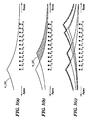
- FIGs. 3 (a-c) shows qualitative pictures of potential distributions in a 12-channel system, where pulses are applied sequentially in electrodes E 1 , E 5 , E 10 , E 11 , and E 12 , in accordance with one embodiment of the invention.
- a first pulse in E1 occurs as shown in Fig. 3(a) .
- the voltage distribution u 1 (x) due to the first pulse in electrode E 1 (upper panel), most neurons will be activated in the immediate neighborhood of the electrode, and the number of activated neurons will decrease with increasing distance to E 1 .
- the second pulse in E 5 occurs immediately after the first pulse and causes potential u 5 (x), as shown in Fig.
- this pulse will activate less new neurons, because due to spatial channel interaction, u 5 (x) is partly masked by u 1 (x), and thus many of the neurons in the vicinity of E 5 have already been excited by the first pulse. These neurons cannot be retriggered again, because they are in refractory states. As shown in Fig. 3(b) , new neurons may be elicited only according to the hatched area below u 5 (x). Similarly, each one of the following pulses can recruit only a fraction of neurons compared to the case where they are activated separately.
- refractory effects in combination with spatial channel interaction will cause a recruitment profile which is roughly derived from the contour potential of the individual sequentially applied potential distributions, as shown in Fig. 3(c) .
- the pulse in electrode E11 is masked by its predecessors and thus does not contribute to the contour potential Note that in the example in Figs. 3 (a-c), the pulse elicited in electrode E 11 cannot activate neurons, because the associated potential distribution is fully masked by the potentials of its predecessors.
- the contour potential of a set of sequentially applied pulses is approximated by a so called "summation potential", which is generated by a set of sign-correlated simultaneous pulses.
- the contour potential has to be obtained from sequential pulses which are applied within a time period shorter than about one absolute refractory period of the nerve fibers. It is stipulated that in this case, the summation potential and contour potential essentially cause the same pattern of neuronal activation.
- the amplitudes of the simultaneous pulses are derived from the sequential amplitudes, but are modified by taking into account spatial potential superposition. Summation- and contour potentials should be equal at the position of the active electrodes. This concept is designated as "channel interaction compensation (CIC)".
- CIC channel interaction compensation
- u n (x) I sequ , n ⁇ r n ⁇ x - x n , where function r n (x) denotes the spatial impulse response associated to electrode number n.
- U max , 1 I 1 ⁇ r 1 0 + I 2 ⁇ r 2 - d + I 3 ⁇ r 3 ⁇ - 2 ⁇ d + ... + I N ⁇ r N ⁇ - N - 1 ⁇ d
- 2 I 1 ⁇ r 1 d + I 2 ⁇ r 2 0 + I 3 ⁇ r 3 - d + ... + I N ⁇ r N ⁇ - N - 2 ⁇ d ⁇
- N I 1 ⁇ r 1 ⁇ N - 1 ⁇ d + I 2 ⁇ r 2 ⁇ N - 2 ⁇ d + I 3 ⁇ r 3 ⁇ N - 3 ⁇ d + ... + I N ⁇ r N 0
- H 0 -1 is the inverse of H 0 .
- the system (4) is simplified by removing non-used current amplitudes from the amplitude vectors (both sequential and simultaneous), and delete the corresponding rows and columns from matrix H 0 . This procedure is designated as "reduction of the CIC system".
- the simultaneous amplitudes obtained from a CIC procedure can include negative solutions. Negative amplitudes mean that pulses with inverted phases are required to achieve the desired summation potential. However, such pulses contradict the principle of sign-correlation and therefore are not applicable and have to be excluded. This requires another reduction of the CIC system and a re-calculation of the remaining amplitudes with a modified interaction matrix. Theoretically, the new solution can again include negative amplitudes, and thus the procedure of recalculations is repeated, until a vector with only positive simultaneous amplitudes is obtained. In the most extreme case, only one amplitude remains, and in this case, trivially "simultaneous" and "sequential" amplitudes are equal.
- responses (7) represent rather crude approximations to reality.
- matrix H has remarkably advantageous properties, as will be shown in the following.
- matrix H is non-singular, if the decay constants are within the ranges [0 ⁇ ⁇ ⁇ 1] and [0 ⁇ ⁇ ⁇ 1]. This can easily be seen, because individual lines and rows are certainly not linear dependent from each other.
- Electrodes 5 and 9 have two neighbors, i.e., 3 and 8, 5 and 9, and 8 and 11, respectively.
- This system is composed of three equations with three unknown variables ⁇ k , ⁇ k , and I k .
- a simultaneous amplitude I k may be fully determined by the sequential amplitude I sequ,k in the same electrode, and the two sequential amplitudes I sequ,k-L1 and I sequ,k+L2 in the neighboring active electrodes.
- the weighting factors a(L 1 ), b(L 1 ,L 2 ), and c(L 2 ) depend on the distances L 1 to the lower, and L 2 to the upper active neighbors.
- the leftmost and rightmost active electrodes may need special consideration.
- the leftmost active electrode has no neighbor at positions with lower indices.
- the summation potential in the direction of lower electrode addresses is decreasing exponentially according to decay parameter ⁇ .
- I sequ,k represents the amplitude of the leftmost amplitude
- the rightmost active electrode has no neighbor at higher electrode positions.
- H - 1 b 0 1 c 1 0 ⁇ 0 0 0 a 1 b 1 1 c 1 ⁇ 0 0 0 0 a 1 b 1 1 ⁇ 0 0 0 ⁇ ⁇ ⁇ ⁇ ⁇ 0 0 0 ⁇ b 1 1 c 1 0 0 0 0 0 ⁇ a 1 b 1 1 c 1 0 0 0 0 0 ⁇ a 1 b 1 1 c 1 0 0 0 ⁇ 0 0 ⁇ a 1 b 1 1 c 1 0 0 0 ⁇ 0 a 1 b 0 1 .
- Matrix H -1 is tri-diagonal with non-zero coefficients only in the three main diagonals. In case of a system reduction, rows and columns of H are deleted resulting in a reduced matrix H'. As derived earlier, the resulting inverse H' -1 is tri-diagonal again, and beside the difference in matrix sizes, only "local changes" of coefficients occur. Thus, if a vector of simultaneous amplitudes has been computed and if it contains negative solutions, these negative solutions need to be removed. Only amplitudes which have been neighboring to the negative amplitudes have to be re-calculated. This feature is extremely advantageous in an iterative CIC procedure.
- the spatial impulse responses depend on the electrode position. Several reasons contribute to this, i.e., the varying diameter of the scala tympani, and also the varying diameter of the intracochlear electrode array.
- impulse responses measured show approximately exponential decays in all electrodes, whereby the slopes towards the apex are shallower than towards the base (i.e., ⁇ > ⁇ ), and the maxima in general are higher in the apical, than in the basal region (see A Kral, R Hartmann, D Mortazavi, R Klinke, "Spatial resolution of cochlear implants: the electrical field and excitation of auditory afferents," Hear. Res. 121, pp.
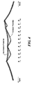
- Fig. 5 shows place dependent impulse responses, in accordance with one embodiment of the invention. Each impulse response has a decay constant ⁇ (towards apex) and ⁇ (towards base).
- ⁇ towards base
- each CIC system described by parameters ⁇ , ⁇ , and ⁇ may be transformed into an equivalent CIC system with parameters ⁇ ' and ⁇ ', and all computational benefits of CIC, based on place-independent impulse responses, can be exploited.
- the ( ⁇ , ⁇ , ⁇ ) and ( ⁇ ', ⁇ ') systems represent different systems, whose (continuous) summation potentials coincide at the positions of the active electrodes, but are different at all other places.
- the stimulation concept presented above is based on sign-correlated simultaneous pulses. Compared to sequential pulsatile stimulation, simultaneous amplitudes are modified by taking into account parameters of intracochlear potential spread.
- the simultaneous approach presented here may be the basis for future stimulation strategies, because it allows for a very substantial increase of the overall stimulation rates without the need to reduce pulse phases to unphysiologically low durations. In particular, a better representation of temporal fine structure information should be possible. As an upper theoretical limit, for a N-channel sequential system, the pulse rate can be increased by a factor of N.
- simultaneous pulses with longer phase durations and reduced pulse amplitudes may be utilized. This advantageously results in a substantial reduction of the power consumption.
- Alternative embodiments of the invention may be implemented as, or otherwise include, a computer program product for use with a computer system.
- Such implementation may include a series of computer instructions fixed either on a tangible medium, such as a computer readable media (e.g., a diskette, CD-ROM, ROM, or fixed disk), or fixed in a computer data signal embodied in a carrier wave that is transmittable to a computer system via a modem or other interface device, such as a communications adapter connected to a network over a medium.
- the medium may be either a tangible medium (e.g., optical or analog communications lines) or a medium implemented with wireless techniques (e.g., microwave, infrared or other transmission techniques).
- the series of computer instructions embodies all or part of the functionality previously described herein with respect to the system.
- Those skilled in the art should appreciate that such computer instructions can be written in a number of programming languages for use with many computer architectures or operating systems.
- such instructions may be stored in any memory device, such as semiconductor, magnetic, optical or other memory devices, and may be transmitted using any communications technology, such as optical, infrared, microwave, or other transmission technologies.
- Such a computer program product may be distributed as a removable medium with accompanying printed or electronic documentation (e.g ., shrink wrapped software), preloaded with a computer system (e.g ., on system ROM or fixed disk), or distributed from a server or electronic bulletin board over the network (e.g., the Internet or World Wide Web).
- printed or electronic documentation e.g ., shrink wrapped software
- a computer system e.g ., on system ROM or fixed disk
- server or electronic bulletin board e.g., the Internet or World Wide Web
Description
- The present invention relates to electrical nerve stimulation, and more particularly, simultaneous electrical nerve stimulation for cochlear implants
- Cochlear implants and other inner ear prostheses are one option to help profoundly deaf or severely hearing impaired persons. Unlike conventional hearing aids that just apply an amplified and modified sound signal; a cochlear implant is based on direct electrical stimulation of the acoustic nerve. Typically, a cochlear implant stimulates neural structures in the inner ear electrically in such a way that hearing impressions most similar to normal hearing are obtained.
-
Figure 1 shows a section view of an ear with a typical cochlear implant system. A normal ear transmits sounds through theouter ear 101 to theeardrum 102, which moves the bones of themiddle ear 103, which in turn excites thecochlea 104. Thecochlea 104 includes an upper channel known as thescala vestibuli 105 and a lower channel known as thescala tympani 106, which are connected by thecochlear duct 107. In response to received sounds transmitted by themiddle ear 103, the fluid filledscala vestibuli 105 andscala tympani 106 function as a transducer to transmit waves to generate electric pulses that are transmitted to thecochlear nerve 113, and ultimately to the brain. Frequency processing seems to change in nature from the basal region of the cochlea, where the highest frequency components of a sound are processed, to the apical regions of the cochlea, where the lowest frequencies are analyzed. - Some persons have partial or full loss of normal sensorineural hearing. Cochlear implant systems have been developed to overcome this by directly stimulating the user's cochlea 104. A typical cochlear prosthesis essentially includes two parts: the speech processor and the implanted
stimulator 108. The speech processor (not shown inFig. 1 ) typically includes a microphone, a power supply (batteries) for the overall system and a processor that is used to perform signal processing of the acoustic signal to extract the stimulation parameters. In state-of-the art prostheses, the speech processor is a behind-the-ear (BTE-) device. The implanted stimulator generates the stimulation patterns and conducts them to the nerve tissue by means of anelectrode array 110 which usually is positioned in the scala tympani in the inner ear. The connection between speech processor and stimulator is usually established by means of a radio frequency (RF-) link. Note that via the RF-link both stimulation energy and stimulation information are conveyed. Typically, digital data transfer protocols employing bit rates of some hundreds of kBit/s are used. - One example of a standard stimulation strategy for cochlear implants is called the "Continuous-Interleaved-Sampling (CIS)" strategy, as described by Wilson BS, Finley CC, Lawson DT, Wolford RD, Eddington DK, Rabinowitz WM, "Better speech recognition with cochlear implants," Nature, vol. 352, 236-238, July 1991, to which the reader is directed for a fuller understanding of the present invention. Signal processing for CIS in the speech processor typically involves the following steps:
- 1. Splitting up of the audio frequency range into spectral bands by means of a filter bank,
- 2. Envelope detection of each filter output signal,
- 3. Instantaneous nonlinear compression of the envelope signal (map law), and.
- 4. Adaptation to thresholds (THR) and most comfortable loudness (MCL) levels
- Each of the stimulation electrodes in the scala tympani is typically associated with a band pass filter of the external filter bank. According to the "tonotopic principle" of the cochlea, high frequency bands are associated with electrodes positioned more closely to the base, and low frequency bands to electrodes positioned more deeply in the direction of the apex, as described by Greenwood DD, "A cochlear frequency-position function for several species - 29 years later," J. Acoust. Soc. Am., 2593-2604, 1990, to which the reader is directed for a fuller understanding of the present invention. For stimulation, charge balanced current pulses - usually biphasic symmetrical pulses - are applied. The amplitudes of the stimulation pulses are obtained by sampling the compressed envelope signals. As the characteristic CIS paradigm, For stimulation, symmetrical biphasic current pulses are applied. The amplitudes of the stimulation pulses are directly obtained from the compressed envelope signals (step (3) of above). These signals are sampled sequentially, and the stimulation pulses are applied in a strictly non-overlapping sequence. Thus, as a typical CIS-feature, only one stimulation channel is active at one time. The overall stimulation rate is comparatively high. For example, assuming an overall stimulation rate of 18kpps, and using an 12 channel filter bank, the stimulation rate per channel is 1.5kpps. Such a stimulation rate per channel usually is sufficient for adequate temporal representation of the envelope signal.
- The influence of various CIS-parameters on speech perception, such as the number of channels and the stimulation rate per channel, etc. has been investigated (see for example: Loizou PC, Poroy O, Dorman M, The effect of parametric variations of cochlear implant processors on speech understanding," J. Acoust. Soc Am. 2000 Aug;108(2):790-802; and Wilson B, Wolford R, Lawson D, Speech processors for Auditory prostheses - Seventh quarterly progress report. NIH Project N01-DC-8-2105, to each of which the reader is directed for a fuller understanding of the present invention) and new concepts aiming at a further improvement have been proposed. For example, one approach is based on the principle of stochastic resonance (see, for example: McNamara B and Wiesenfeld K, "Theory of stochastic resonance" Phys. Rev. A, 39:4854-4869; Rubinstein JT, Wilson BS, Finley CC, Abbas PJ, "Pseudospontaneous activity: stochastic independence of auditory nerve fibers with electrical stimulation," Hear. Res. 127, 108-118, 1999; and Morse RP and Evans EF, "Additive noise can enhance temporal coding in a computational model of analogue cochlear implant stimulation," Hear. Res. 133, 107-119, 1999, to each of which the reader is directed for a fuller understanding of the present invention). The basic idea is to mimic spontaneous activity in the neurons to provide a more natural representation of the envelope signals in the spiking patterns. However, so far this and other approaches have not found their way into broad clinical applications, mainly because no substantial improvement in of CI performance as compared to CIS has been found.
- At present, the incorporation of so called "fine structure information" seems to be the most promising way to further improve CIS. Following Hilbert (i.e., Hilbert D, "Grundzüge einer allgemeinen Theorie linearer Integralgleichungen," Teubner, Leipzig, 1912, to which the reader is directed for a fuller understanding of the present invention), any signal can be represented as the product of a slowly varying envelope and a rapidly varying signal containing temporal fine structure. The current CIS strategy uses only the envelope information; the fine structure information is discarded. In the response of a CIS band pass filter, temporal fine structure information is represented by position of the zero crossings of the signal and tracks the exact spectral position of the center of gravity of the signal within its band pass region, including temporal transitions of such centers of gravity. For example, the temporal transitions of formant frequencies in vowel spectra are highly important cues for the perception of preceding plosives or other unvoiced utterances. Furthermore, a close look at the details of a band pass filter output reveals that the pitch frequency is clearly present in the temporal structure of the zero crossings. The relative importance of envelope and fine structure information is investigated in an experiment described in Smith ZM, Delgutte B, Oxenham AJ, "Chimaeric sounds reveal dichotomies in auditory perception," Nature, vol. 416, 87-90, March 2002, to which the reader is directed for a fuller understanding of the present invention. There is some consensus that for an intermediate number of 4 to 16 processing channels, the envelope is most important for speech reception whereas the temporal fine structure is most important for pitch perception (melody recognition) and sound localization. In the light of these results, standard CIS is a good choice with respect to speech intelligibility (e.g., for American English). However, regarding music perception and perception of so called tone languages (e.g., Mandarin Chinese, Cantonese, Vietnamese, Thai, etc.), CIS might be suboptimal and and new stimulation strategies containing both envelope and temporal fine structure information might have the potential for a substantial improvement of CI performance. This assumption is supported, for example, by the study in FG Zeng, KB Nie, S Liu, GS Stickney, E Del Rio, YY Kong, HB Chen, "Speech recognition with amplitude and frequency modulations," Proc. nat. acad. of science 102: 2293-2298, 2005, to which the reader is directed for a fuller understanding of the present invention, where it is demonstrated that slowly varying frequency modulations can be perceived by cochlear implant subjects and thus an appropriate incorporation in future stimulation strategies is recommended.
- Considering such new stimulation strategies it is clear that an increase of information will require higher pulse repetition rates per channel. Adhering to the basic CIS-paradigm of strictly non-overlapping pulses, an increase in pulse rates can only be achieved if the pulse durations get shorter. However, the pulse duration cannot be reduced arbitrarily, because shorter pulses require higher pulse amplitudes for sufficient loudness, and pulse amplitudes are limited for various practical reasons, such as a maximum implant supply voltage. Besides, there exists a fundamental neural time constant due to properties of nodes of Ranvier in myelinated nerve fibers, which is about τ = 20-30 µs in the auditory nerve (see, for example, Frijns J and ten Kate J, "A model of myelinated nerve fibers for electrical prosthesis design," Med. Biol. Eng. Comput., vol 32, pp. 391-398, 1994, to which the reader is directed for a fuller understanding of the present invention.). Although the response of the transmembrane potentials to a stimulation pulse is faster than the response of a simple first order system ("spectral acceleration," see, for example, Zierhofer CM, "Analysis of a linear model for electrical stimulation of axons - critical remarks on the "activating function concept"," IEEE Trans. BME, Vol. 48, No. 2, Feb. 2001, to which the reader is directed for a fuller understanding of the present invention.), phase durations significantly shorter than τ should be avoided in order to avoid current shortcuts due to the membrane capacitances.
-
WO 0113991 (A1 - Clemens Zierhofer et al "Simultaneous stimulation based on channel interaction compensation ", 15 July 2007, CIAP 2007 Conference on Implantable Auditory Prostheses, Granlibakken, USA discloses an approach for the simultaneous application of pulsatile stimuli at the presence of spatial channel interaction. Pulses are 100% synchronous in time and have equal phase polarities. An exponential model of spatial potential distribution within the scala tympani uses two different decay constants α and β towards the apex and base, respectively. If a subset of electrodes is stimulated simultaneously, the associated sequential amplitudes are taken and reduced simultaneous amplitudes are computed. Sequential and simultaneous amplitudes are related to each other via an "Interaction Matrix".
- Stickney et al "Improving Frequency Discrimination in Cochlear Implant Users ", 12 February 2007, The Association for Research in Otolaryngology, 30th Annual Midwinter meeting of the ARO, Denver disclosed two methods for potentially improving frequency discrimination were investigated in MED-EL cochlear implant users. The first utilizes a temporal fine structure coding method in the low frequency bands, called Channel Specific Sampling Sequences (CSSS), where a series of pulse packets are modulated by temporal fine structure and combined with traditional envelope coding. The second method investigated the use of virtual channels, where intermediate frequencies can be perceived by varying relative amplitudes of adjacent electrodes.
- In accordance with one embodiment of the invention which is defined in the claims, a method of simultaneously activating at least two electrodes in a multichannel electrode array is presented. The method includes calculating pulse amplitudes of the electrodes in the multichannel array by taking into account parameters of spatial channel interaction reflecting geometric overlapping of electrical fields from each electrode. Calculating is based, at least in part, on place-independent impulse responses characterized by a first exponential decay constant α at a first side of the electrode and a second exponential decay constant β at a second side of the electrode, such that the first exponential decay constant α is the same for each electrode in the array, and the second exponential decay constant β is the same for each electrode in the array. In accordance with the invention, calculating further includes applying electrode-specific weighting factors to account for place-dependent impulse responses. Calculating may include using properties of a tri-diagonal matrix. The first exponential decay constant α may not equal the second exponential decay constant β. The method may further include simultaneously activating the at least two electrodes using sign-correlated pulses. Activating the two electrodes may stimulate the acoustic nerve. The multichannel electrode array may use a monopolar configuration having a remote ground. The multichannel electrode array may include a first electrode at the beginning of the array, and a second electrode at the end of the array, and wherein the method for calculating includes introducing a fictitious electrode neighboring at least one of the first electrode and the second electrode.
- In further related embodiments of the invention, calculating may include determining a desired potential for a given position relative to the electrode array, the desired potential determined based, at least in part, on a continuous-interleaved-sampling strategy. Amplitudes of the simultaneous, sign-correlated pulses associated with electrodes are calculated by adding resulting potentials from each of the sign-correlated pulses at the given position, so as to provide a total potential at the given position substantially equal to the desired potential.
- In accordance with another embodiment of the invention, a cochlear implant system includes a multi-channel electrode array having at least two electrodes. A stimulator calculates amplitudes of electrode stimulation signals associated with the electrodes as a function of spatial channel interaction reflecting geometric overlapping of electrical fields from each electrode. Calculating is based, at least in part, on place-independent impulse responses characterized by a first exponential decay constant α at a first side of the electrode and a second exponential decay constant β at a second side of the electrode, such that the first exponential decay constant α is the same for each electrode in the array, and the second exponential decay constant β is the same for each electrode in the array. In accordance with the invention, the simulator applies eletrode-specific place-dependent weighting factors to account for place-dependent impulse responses when calculating the amplitudes of the electrode stimulation signals.
- The implant system may use properties of a tri-diagonal matrix to determine the amplitudes of the electrode signals. The first exponential decay constant α may not equal the second exponential decay constant β. The electrode array may be arranged in a monopolar electrode configuration having a remote ground. The stimulator may simultaneously activate the at least two electrodes using sign-correlated pulses. The multichannel electrode array may be part of a cochlear implant for simulating the acoustic nerve. The system may further include a speech processor that includes a filter bank for receiving an acoustic audio signal, each filter in the bank of filters associated with one of the electrodes in the multi-channel electrode array. The speech processor derives a weighting factor for each electrode in the multi-channel electrode array from an associated channel filter.
- In accordance with another embodiment of the invention, a computer program product for use on a computer system for stimulating electrodes in a multichannel electrode array is presented. Each channel is associated with an electrode in the array. The computer program product includes a computer usable medium having computer readable program code thereon. The computer readable program code includes program code for calculating amplitudes of electrode stimulation signals associated with electrodes as a function of spatial channel interaction reflecting geometric overlapping of electrical fields from each electrode. Calculating is based, at least in part, on place-independent impulse responses characterized by a first exponential decay constant α at a first side of the electrode and a second exponential decay constant β at a second side of the electrode, such that the first exponential decay constant α is the same for each electrode in the array, and the second exponential decay constant β is the same for each electrode in the array. In accordance with related embodiments of the invention, the program code for calculating further includes program code for applying place-dependent weighting factors to account for place-dependent impulse responses.
The program code for calculating may include using properties of a tri-diagonal matrix. The first exponential decay constant α may not equal the second exponential decay constant β. The computer program product may further include program code for simultaneously stimulating the at least two electrodes using sign-correlated pulses. The multichannel electrode array may be part of a cochlear implant for simulating the acoustic nerve. The multichannel electrode array may use a monopolar configuration having a remote ground. The multichannel electrode array may include a first electrode at the beginning of the array, and a second electrode at the end of the array, and wherein the program code for calculating includes introducing a fictitious electrode neighboring at least one of the first electrode and the second electrode. - In further related embodiments of the invention, the program code for calculating may include program code for determining a desired potential for a given position relative to the electrode array, the desired potential determined based, at least in part, on a continuous-interleaved-sampling strategy. Amplitudes of the simultaneous, sign-correlated pulses associated with electrodes are calculated by adding resulting potentials from each of the sign-correlated pulses at the given position, so as to provide a total potential at the given position substantially equal to the desired potential.
- The foregoing features of the invention will be more readily understood by reference to the following detailed description, taken with reference to the accompanying drawings, in which:
-
Fig. 1 shows a section view of an ear with a typical cochlear implant system; -
Fig. 2 shows a one-dimensional model of a cochlea and includes a 12-channel electrode array positioned within the scala tympani and a return electrode outside the scala tympani, in accordance with an embodiment of the invention; -
Figs. 3 (a-c) shows qualitative pictures of potential distributions in a 12-channel system, where pulses are applied sequentially in electrodes E1, E5, E10, E11, and E12, in accordance with one embodiment of the invention. -
Fig. 4 shows potential distributions of a 12-channel simultaneous stimulation system, in accordance with an embodiment of the invention. -
Fig. 5 shows place dependent impulse responses, in accordance with an embodiment of the invention. - In illustrative embodiments, a simultaneous stimulation method and system for cochlear implants is presented. A set of sequential stimulation pulses - which would be applied within a time duration of less than or equal to about the absolute refractory period of neurons - is replaced by a set of simultaneous pulses with amplitudes that are adapted taking into account parameters of spatial channel interaction. The computation amount for amplitude adaptation may be reduced significantly, if the unit responses in individual electrodes have exponential decays involving two different decay constants α (towards apex) and β (towards base). As shown in general, in this case the inverse of the channel interaction matrix is tridiagonal. The new paradigm is based on pulses with technically reasonable phase durations. Theoretically the number of pulses per second in an N-channel system may be increased from N to up to N2. Simultaneous stimulation pulses are typically sign-correlated in a monopolar electrode configuration. Results obtained from cochlear implant patients show at least the same speech perception for the standard sequential and the simultaneous paradigm, if both conditions use the same pulse rates.
- In various embodiments of the invention, the system uses simultaneous, sign-correlated stimulation pulses in a monopolar electrode configuration. Sign correlated pulses are generally defined by two conditions: (i) All pulses are substantially 100% synchronously in time, and (ii) all pulses have substantially the same current direction (i.e., equal sign).
-
Fig. 2 shows a one-dimensional model of a cochlea which is represented by an unrolled conductive tube, and includes a 12-channel electrode array 260 positioned within the scala tympani and areturn electrode 240 outside (usually under the temporal muscle), in accordance with one embodiment of the invention. Such a scheme is designated as a monopolar electrode configuration. The electrode array, indicated by electrode contacts E1-E12 220-231, is assumed to be surrounded by fluids and tissues which have a significantly higher electric conductance than the bony cochlear walls (see, for example, Suessermann MF, Spelman FA, "Lumped-parameter model for in vivo cochlear stimulation," IEEE Trans. BME, Vol. 40, No. 3, March 1993, to which the reader is directed for a fuller understanding of the present invention). The excitable neurons are presumed outside the scala tympani in the so called nerve fiber channel behind the bony spiral lamina (see, for example, Geisler CD "From sound to synapse," ISBN 0-19-510025-5, Oxford University Press, 1998, to which the reader is directed for a fuller understanding of the present invention). Stimulation pulses are generated in current sources Q1-Q12 200-231. InFig. 1 , sign-correlated biphasic pulses with different amplitudes are generated simultaneously incurrent sources Q 1 200,Q 5 204,Q 10 209, andQ 12 211 so as to generate biphasic waveforms i1(t) 250, i5(t) 251, i10(t) 252, and i12(t) 253. The sum of all current pulses is forced to flow through the reference electrode outside the cochlea. However, since all active electrodes are within the same conductive medium, the electrical potentials caused by the individual active electrodes will show considerable geometric overlapping in the scala tympani itself, and at the position of the neurons. This effect is known as spatial channel interaction. However, despite channel interaction, sign correlation in combination with the monopolar configuration ensures that the sum of all currents is flowing into theremote ground electrode 240, i.e., 100% of the charges in both pulse phases are forced to flow through the region of the neurons. Note that this feature is characteristic for the configuration as presented and different to the situation of so called bipolar- or multipolar configurations [see, for example: Van den Honert C, Stypulkowski, "Single fiber mapping of spatial excitation patterns in the electrically stimulated auditory nerve," Hear. Res. 29, 195-206, 1987; and Miyoshi S, Sakajiri M, Ifukube T, Matsushima J, "Evaluation of the tripolar electrode stimulation method by numerical analysis and animal experiments for cochlear implants," Acta Otol. Suppl. 532:123-5, 1997, to each of which the reader is directed for a fuller understanding of the present invention). For example, in a bipolar configuration, sink- and source electrodes are both within the scala tympani and separated typically by 1 to 3 mm. The remote ground electrode is omitted. For stimulation, the active electrodes are operated simultaneously with opposite signs of the pulse phases. While this leads to a better concentration of electrical fields in the vicinity of the electrodes and thus defuses channel interaction, there are important disadvantages. Because the high conductance of the intracochlear medium represents a low impedance shunt between the activated electrodes, most of the current is flowing within the scala tympani and does not reach the position of the neurons. As compared to the monopolar configuration, substantially higher stimulation pulse amplitudes are required for suprathreshold stimulation, which results in a significantly increased implant power consumption. In addition, very high current densities occur at metal surfaces of the electrode contacts which might cause safety problems, as described by Brummer SB, Turner MJ, "Electrical stimulation with Pt electrodes: II - Estimation of maximum surface redox (theoretical non-gassing) limits ," IEEE Trans. BME, Vol. 24, Sept. 1977, to which the reader is directed for a fuller understanding of the present invention). - The starting point of the following discussion is a standard CIS paradigm. Consider the voltage potentials in the scala tympani caused by a sequence of sequentially applied biphasic current pulses. In the following only the depolarizing phases of the stimulation pulses are regarded, and for convenience, a positive sign is associated to the respective potential distributions. The simple one-dimensional model of the cochlea as in
Fig. 2 is used again, and purely ohmic behavior of the tissue is assumed (see A Kral, R Hartmann, D Mortazavi, R Klinke, "Spatial resolution of cochlear implants: the electrical field and excitation of auditory afferents," Hear. Res. 121, pp. 11-28, July 1998, to which the reader is directed for a fuller understanding of the present invention).Figs. 3 (a-c) shows qualitative pictures of potential distributions in a 12-channel system, where pulses are applied sequentially in electrodes E1, E5, E10, E11, and E12, in accordance with one embodiment of the invention. A first pulse in E1 occurs as shown inFig. 3(a) . Regarding the voltage distribution u1(x) due to the first pulse in electrode E1 (upper panel), most neurons will be activated in the immediate neighborhood of the electrode, and the number of activated neurons will decrease with increasing distance to E1. The second pulse in E5 occurs immediately after the first pulse and causes potential u5(x), as shown inFig. 3(b) . However, this pulse will activate less new neurons, because due to spatial channel interaction, u5(x) is partly masked by u1(x), and thus many of the neurons in the vicinity of E5 have already been excited by the first pulse. These neurons cannot be retriggered again, because they are in refractory states. As shown inFig. 3(b) , new neurons may be elicited only according to the hatched area below u5(x). Similarly, each one of the following pulses can recruit only a fraction of neurons compared to the case where they are activated separately. If all sequential pulses are applied within a period equal to or shorter than about the absolute refractory period of the neurons (≈ 1 ms), refractory effects in combination with spatial channel interaction will cause a recruitment profile which is roughly derived from the contour potential of the individual sequentially applied potential distributions, as shown inFig. 3(c) . The pulse in electrode E11 is masked by its predecessors and thus does not contribute to the contour potential Note that in the example inFigs. 3 (a-c), the pulse elicited in electrode E11 cannot activate neurons, because the associated potential distribution is fully masked by the potentials of its predecessors. - In illustrative embodiments, the contour potential of a set of sequentially applied pulses is approximated by a so called "summation potential", which is generated by a set of sign-correlated simultaneous pulses. The contour potential has to be obtained from sequential pulses which are applied within a time period shorter than about one absolute refractory period of the nerve fibers. It is stipulated that in this case, the summation potential and contour potential essentially cause the same pattern of neuronal activation. The amplitudes of the simultaneous pulses are derived from the sequential amplitudes, but are modified by taking into account spatial potential superposition. Summation- and contour potentials should be equal at the position of the active electrodes. This concept is designated as "channel interaction compensation (CIC)". E.g., if the pulse amplitudes in electrodes E1, E5, E10, and E12 in the example in
Fig. 2 are modified accordingly and applied simultaneously, they result in a summation potential as depicted inFig. 4 . As demanded, summation potential (circles) and contour potentials (+ signs) coincide at the electrode positions. Between these positions, the summation potential is less pronounced as compared to the sequential contour. - Assuming a one-dimensional model of the cochlea and a linear and ohmic behavior of the tissue, the voltage distribution un(x) caused by a single current amplitude Isequ,n in electrode number n at position xn is given by


- In the current concept it is demanded that simultaneous amplitudes In cause a summation potential, which is equal to the peak potentials at the positions of the active electrodes. For convenience, equidistant electrodes with an electrode spacing d = xn - xn-1 are assumed. If all electrodes of an N-channel system are activated simultaneously, the following set of equations is obtained

- Using vector notation and inserting (2) in (3) yields the relationship between sequential- and simultaneous amplitudes


- The simultaneous amplitudes can be computed with

- In general the simultaneous amplitudes obtained from a CIC procedure can include negative solutions. Negative amplitudes mean that pulses with inverted phases are required to achieve the desired summation potential. However, such pulses contradict the principle of sign-correlation and therefore are not applicable and have to be excluded. This requires another reduction of the CIC system and a re-calculation of the remaining amplitudes with a modified interaction matrix. Theoretically, the new solution can again include negative amplitudes, and thus the procedure of recalculations is repeated, until a vector with only positive simultaneous amplitudes is obtained. In the most extreme case, only one amplitude remains, and in this case, trivially "simultaneous" and "sequential" amplitudes are equal.
- With respect to a practical realization in a cochlear implant system with limited space- and power resources, the iterative CIC-procedure as described is a computational challenge. In particular, matrix inversions cause problems. Standard matrix inversion procedures, such as, e.g., the Gauss-Jordan algorithm, are difficult to implement for real-time operations. On the other hand, storing coefficients of inverted matrices requires lots of memory. A short consideration reveals that for a CIC system with K simultaneous amplitudes, 2K different inverse matrices with an overall number of

- In illustrative embodiments of the invention, the computational cost for CIC may be reduced dramatically, if the impulse responses rn(x) are assumed to be place-independent functions consisting of two exponentially decaying branches, i.e.,


- With α and β, inserting (7) into (5) yields an interaction matrix

- Fortunately, this matrix H has remarkably advantageous properties, as will be shown in the following. As a first important feature, matrix H is non-singular, if the decay constants are within the ranges [0 ≤ α < 1] and [0 ≤ β < 1]. This can easily be seen, because individual lines and rows are certainly not linear dependent from each other. With (9), system (4) can be written as

- For the following discussion - consistent with
Fig. 3 - electrode indices are assumed to increase from apex to base, i.e., from left to right. In a CIC reduction procedure typically a subset of electrodes is selected, and equations for unused sequential amplitudes are deleted and unused simultaneous amplitudes are set to zero. For example, consider a 12-channel system, where the electrodes with indices 3, 5, 8, 9, and 11 have been selected for simultaneous stimulation. Electrode 3 is the leftmost electrode with its next neighbor 5 to the right, and electrode 11 is the rightmost electrode with its next neighbor 9 to the left. Electrodes 5, 8, and 9 have two neighbors, i.e., 3 and 8, 5 and 9, and 8 and 11, respectively. In general, if an electrode with index k has two neighbors with indices k-L1 and k+L2 (L1≥ 1, L2≥ 1), the associated amplitudes are Isequ,k, Isequ,k-L1 and Isequ,k+L2. The definition of polynomials σn and ρn (n = 1,2, ..., N)

- A detailed look at (10) reveals the following identities


- Inserting (13) and (14) into (12) yields

- This system is composed of three equations with three unknown variables σk, ρk, and Ik. Isolation of Ik results in


- Thus, in general, a simultaneous amplitude Ik may be fully determined by the sequential amplitude Isequ,k in the same electrode, and the two sequential amplitudes Isequ,k-L1 and Isequ,k+L2 in the neighboring active electrodes. The weighting factors a(L1), b(L1,L2), and c(L2) depend on the distances L1 to the lower, and L2 to the upper active neighbors.
- The leftmost and rightmost active electrodes may need special consideration. The leftmost active electrode has no neighbor at positions with lower indices. However, the summation potential in the direction of lower electrode addresses is decreasing exponentially according to decay parameter α. Thus, if Isequ,k represents the amplitude of the leftmost amplitude, a (fictitious) neighboring electrode at position k-1 (L1 = 1) with an amplitude αIsequ,k may be introduced. Inserting into (16) yields

- With (17), coefficient b0(L2) becomes

- Similarly, the rightmost active electrode has no neighbor at higher electrode positions. In this region, the summation potential is exponentially decaying according to β. If Isequ,k represents the amplitude of the rightmost amplitude, a (fictitious) neighboring electrode at position k+1 (L2 = 1) with resulting amplitude βIsequ,k can be may be introduced. Inserting into (16) yields

- With (17), coefficient b0(L1) becomes

- With (17), (19), and (21) the inverse matrix H-1 of (9) is given by

- Matrix H-1 is tri-diagonal with non-zero coefficients only in the three main diagonals. In case of a system reduction, rows and columns of H are deleted resulting in a reduced matrix H'. As derived earlier, the resulting inverse H'-1 is tri-diagonal again, and beside the difference in matrix sizes, only "local changes" of coefficients occur. Thus, if a vector of simultaneous amplitudes has been computed and if it contains negative solutions, these negative solutions need to be removed. Only amplitudes which have been neighboring to the negative amplitudes have to be re-calculated. This feature is extremely advantageous in an iterative CIC procedure.
- For example, consider a 12-channel system with simultaneous stimulation of electrodes E1, E5, E10, E11, and E12. The resulting reduced system is given by

- The distances between active electrodes are directly reflected in the matrix coefficients of H'-1. Assuming that the computation of the simultaneous amplitudes yields a negative result I11, a further system reduction is required. Amplitudes Isequ,11 and I11 are removed from the amplitude vectors, and the fourth row and column from H'-1 . The resulting new system is

- Note that the coefficients in rows 1 and 2 of matrices H'-1 and H"-1 have not changed, and thus the amplitudes I1 and I5 do not have to be re-calculated. Coefficient changes affect only rows (and columns) 3 and 4 of H"-1, and thus only
electrodes 10 and 12, the previous neighbors of electrode 11, change their amplitude due to new mutual distances. - The amount of memory required to store coefficients a(L1), b(L1,L2), c(L2), b0(L2), b0(L1) of all possible inverse matrices of an K-channel CIC system is very low as compared to a CIC system with arbitrary responses. Using b(L1,L2) = b(L2,L1), a short calculation shows that an overall number of possible coefficients is


- In general, the spatial impulse responses depend on the electrode position. Several reasons contribute to this, i.e., the varying diameter of the scala tympani, and also the varying diameter of the intracochlear electrode array. For example, impulse responses measured show approximately exponential decays in all electrodes, whereby the slopes towards the apex are shallower than towards the base (i.e., α > β), and the maxima in general are higher in the apical, than in the basal region (see A Kral, R Hartmann, D Mortazavi, R Klinke, "Spatial resolution of cochlear implants: the electrical field and excitation of auditory afferents," Hear. Res. 121, pp. 11-28, July 1998, to which the reader is directed for a fuller understanding of the present invention) . Impulse responses like this can be approximated by multiplying r(x) in (7) with electrode specific weighting factors cn (n = 1, 2, ..., N), i.e.,

- Inserting (25) into (5), and with definitions (8) for α and β, the resulting interaction matrix is

- It can easily be shown that Hc may be represented as a matrix product


- With (27) the inverse interaction matrix is simply

- Inserting Hc -1 into (5) yields


- This represents a system based on matrix H as used for place independent responses. Place dependence is incorporated by multiplying the sequential amplitudes with their associated weights, and dividing the CIC results by their respective weights. Regarding a practical realization of a CIC system, the computational amount is only slightly increased as compared to place independent responses r(x). However, all computational advantages of matrix H concerning iterative CIC procedures and matrix inversions can still be fully exploited.
- A mathematically elegant solution may be obtained for the special case, when the weights cn in (25) are assumed to be distributed exponentially, i.e., cn = γn (n = 1, 2, ..., N), with γ as a constant. For example,
Fig. 5 shows place dependent impulse responses, in accordance with one embodiment of the invention. Each impulse response has a decay constant α (towards apex) and β (towards base). A place dependent weighting factor is located on an exponential curve defined by parameter γ. - The impulse responses rn(x) are


- This matrix Hc is identical to a matrix H in (9), when constants α, and β simply are replaced by α' and β' with

- Thus, in various embodiments of the invention, each CIC system described by parameters α, β, and γ may be transformed into an equivalent CIC system with parameters α' and β', and all computational benefits of CIC, based on place-independent impulse responses, can be exploited. Note that the (α, β, γ) and (α', β') systems represent different systems, whose (continuous) summation potentials coincide at the positions of the active electrodes, but are different at all other places.
- The stimulation concept presented above is based on sign-correlated simultaneous pulses. Compared to sequential pulsatile stimulation, simultaneous amplitudes are modified by taking into account parameters of intracochlear potential spread. The simultaneous approach presented here may be the basis for future stimulation strategies, because it allows for a very substantial increase of the overall stimulation rates without the need to reduce pulse phases to unphysiologically low durations. In particular, a better representation of temporal fine structure information should be possible. As an upper theoretical limit, for a N-channel sequential system, the pulse rate can be increased by a factor of N.
- An efficient implementation of the CIC algorithm is possible, if for each stimulation electrode the spatial impulse response can be approximated by two exponentially decaying branches with decay constants α towards the apex, and β towards the base. This is also valid for the case when the impulse responses are place-dependent and differ by a constant factor. In particular, the properties of a tri-diagonal inverse interaction matrix can be exploited.
- If the simultaneous stimulation paradigm is not used to increase the overall stimulation rate, but the overall stimulation rate is kept constant instead, simultaneous pulses with longer phase durations and reduced pulse amplitudes may be utilized. This advantageously results in a substantial reduction of the power consumption.
- Alternative embodiments of the invention, may be implemented as, or otherwise include, a computer program product for use with a computer system. Such implementation may include a series of computer instructions fixed either on a tangible medium, such as a computer readable media (e.g., a diskette, CD-ROM, ROM, or fixed disk), or fixed in a computer data signal embodied in a carrier wave that is transmittable to a computer system via a modem or other interface device, such as a communications adapter connected to a network over a medium. The medium may be either a tangible medium (e.g., optical or analog communications lines) or a medium implemented with wireless techniques (e.g., microwave, infrared or other transmission techniques). The series of computer instructions embodies all or part of the functionality previously described herein with respect to the system. Those skilled in the art should appreciate that such computer instructions can be written in a number of programming languages for use with many computer architectures or operating systems. Furthermore, such instructions may be stored in any memory device, such as semiconductor, magnetic, optical or other memory devices, and may be transmitted using any communications technology, such as optical, infrared, microwave, or other transmission technologies. It is expected that such a computer program product may be distributed as a removable medium with accompanying printed or electronic documentation (e.g., shrink wrapped software), preloaded with a computer system (e.g., on system ROM or fixed disk), or distributed from a server or electronic bulletin board over the network (e.g., the Internet or World Wide Web).
- The described embodiments of the invention are intended to be merely exemplary and numerous variations and modifications will be apparent to those skilled in the art. All such variations and modifications are intended to be within the scope of the present invention as defined in the appended claims.
Claims (22)
- A method performed by a speech processor for extracting stimulation parameters for simultaneously activating at least two electrodes (E1-E12) in a multichannel electrode array (260) having N channels, the method comprising÷ calculating pulse amplitudes of the electrodes (E1-E12) in the multichannel array (260) by taking into account parameters of spatial channel interaction reflecting geometric overlapping of electrical fields from each electrode, wherein calculating is based, at least in part, on place-independent impulse responses characterized by a first exponential decay constant α at a first side of the electrode and a second exponential decay constant β at a second side of the electrode, such that the first exponential decay constant α is the same for each electrode in the array (260), and the second exponential decay constant β is the same for each electrode in the array (260), characterized in that:calculating further includes applying electrode-specific weighting factors cn (n = 1,2, ..., N) to account for place-dependent impulse responses.
- The method of claim 1, wherein calculating includes using properties of a tri-diagonal matrix.
- The method according to claim 1, wherein the first exponential decay constant α does not equal the second exponential decay constant β.
- The method of claim 1, wherein calculating includes;
determining a desired potential for a given position relative to the electrode array (260), the desired potential determined based, at least in part, on a continuous-interleaved-sampling strategy;
determining amplitudes of simultaneous, sign-correlated pulses associated with the electrodes (E1-E12) by adding resulting potentials from each of the sign-correlated pulses at the given position, so as to provide a total potential at the given position substantially equal to the desired potential. - The method according to claim 1, wherein the multichannel electrode array (260) uses a monopolar configuration having a remote ground (240).
- The method according to claim 1, wherein the multichannel electrode array (260) includes a first electrode E1 at the beginning of the array, and a second electrode E12 at the end of the array, and wherein the method for calculating includes introducing a fictitious electrode neighboring at least one of the first electrode E1 and the second electrode E12.
- A cochlear implant system comprising:a multi-channel electrode array (260) having N channels and including at least two electrodes (E1-E12); and a stimulator (108) that calculates amplitudes of electrode stimulation signals associated with the electrodes (E1-E12) as a function of spatial channel interaction reflecting geometric overlapping of electrical fields from each electrode (E1-E12), wherein calculating is based, at least in part, on place-independent impulse responses characterized by a first exponential decay constant α at a first side of the electrode and a second exponential decay constant β at a second side of the electrode, such that the first exponential decay constant α is the same for each electrode in the array (260), and the second exponential decay constant β is the same for each electrode in the array (260), characterized in that:calculating includes applying electrode-specific weighting factors cn (n = 1,2, ..., N) to account for place-dependent impulse responses.
- The implant system according to claim 7, wherein the first exponential decay constant α does not equal the second exponential decay constant β.
- The implant system according to claim 7, wherein the stimulator (108) uses properties of a tri-diagonal matrix to determine the amplitudes of the electrode signals.
- The implant system according to claim 7, wherein the electrode array (260) is arranged in a monopolar electrode configuration having a remote ground (240).
- The implant system according to claim 7, wherein the stimulator (108) simultaneously activates the at least two electrodes (E1-E12) using sign-correlated pulses.
- The implant system according to claim 7, further comprising a speech processor that includes a filter bank for receiving an acoustic audio signal, each filter in the bank of filters associated with one of the electrodes (E1-E12) in the multi-channel electrode array (260), and wherein the speech processor derives a weighting factor for each electrode (E1-E12) in the multi-channel electrode array (260) from an associated channel filter.
- The implant system according to claim 7, wherein the multichannel electrode array (260) includes a first electrode E1 at the beginning of the array (260), and a second electrode E12 at the end of the array (260), and wherein the stimulator introduces a fictitious electrode neighboring at least one of the first electrode E1 and the second electrode E12 when calculating the amplitudes.
- A computer program product for use on a computer system for stimulating electrodes (E1-E12) in a multichannel electrode array (260) having N channels, each channel associated with an electrode in the array (260), the computer program product comprising a computer usable medium having computer readable program code thereon, the computer readable program code including program code for calculating amplitudes of electrode stimulation signals associated with the electrodes (E1-E12) in the electrode array (260) as a function of spatial channel interaction reflecting geometric overlapping of electrical fields from each electrode (E1-E12), wherein calculating is based, at least in part, on place-independent impulse responses characterized by a first exponential decay constant α at a first side of the electrode and a second exponential decay constant β at a second side of the electrode, such that the first exponential decay constant α is the same for each electrode in the array (260), and the second exponential decay constant β is the same for each electrode in the array (260), characterized in that:the program code for calculating further includes applying place-dependent weighting factors cn (n = 1,2, ..., N) to account for place-dependent impulse responses.
- The computer program product according to claim 14, wherein the program code for calculating includes program code for using properties of a tri-diagonal matrix.
- The computer program product according to claim 14, wherein the first exponential decay constant α does not equal the second exponential decay constant β.
- The computer program product according to claim 14, wherein the program code for calculating includes;
program code for determining a desired potential for a given position relative to the electrode array (260), the desired potential determined based, at least in part, on a continuous-interleaved-sampling strategy;
program code for determining amplitudes of simultaneous, sign-correlated pulses associated with at least two electrodes (E1-E12) of the multi-channel array (260) by adding resulting potentials from each of the sign-correlated pulses at the given position, so as to provide a total potential at the given position substantially equal to the desired potential. - The computer program product according to claim 14, further comprising program code for simultaneously stimulating the at least two electrodes (E1-E12) using sign-correlated pulses.
- The computer program product according to claim 14, wherein the multichannel electrode array (260) includes a first electrode E1 at the beginning of the array (260), and a second electrode E12 at the end of the array (260), and wherein the program code for calculating includes program code for introducing a fictitious electrode neighboring at least one of the first electrode E1 and the second electrode E12.
- The method of claim 1, wherein weighting factors cn are distributed exponentially, cn = γn (n = 1, 2, ..., N).
- The implant system according to claim 7, wherein weighting factors cn are distributed exponentially, cn = γn (n = 1, 2, ..., N).
- The computer program product of claim of claim 14, wherein weighting factors cn are distributed exponentially, cn = γn (n = 1, 2, ..., N).
Applications Claiming Priority (2)
| Application Number | Priority Date | Filing Date | Title |
|---|---|---|---|
| US97147307P | 2007-09-11 | 2007-09-11 | |
| PCT/US2008/075984 WO2009036146A1 (en) | 2007-09-11 | 2008-09-11 | Simultaneous intracochlear stimulation |
Publications (2)
| Publication Number | Publication Date |
|---|---|
| EP2197544A1 EP2197544A1 (en) | 2010-06-23 |
| EP2197544B1 true EP2197544B1 (en) | 2015-08-05 |
Family
ID=39869245
Family Applications (1)
| Application Number | Title | Priority Date | Filing Date |
|---|---|---|---|
| EP08799455.4A Active EP2197544B1 (en) | 2007-09-11 | 2008-09-11 | Simultaneous intracochlear stimulation |
Country Status (8)
| Country | Link |
|---|---|
| EP (1) | EP2197544B1 (en) |
| JP (1) | JP5399396B2 (en) |
| KR (1) | KR101543814B1 (en) |
| CN (1) | CN101801455B (en) |
| AU (1) | AU2008298928B2 (en) |
| CA (1) | CA2698886C (en) |
| RU (1) | RU2500440C2 (en) |
| WO (1) | WO2009036146A1 (en) |
Cited By (1)
| Publication number | Priority date | Publication date | Assignee | Title |
|---|---|---|---|---|
| RU2722852C1 (en) * | 2019-12-02 | 2020-06-04 | Общество с ограниченной ответственностью (ООО) "Производственная компания "АЛЬТОНИКА" (ООО "ПК "Альтоника") | Cochlear implantation device |
Families Citing this family (10)
| Publication number | Priority date | Publication date | Assignee | Title |
|---|---|---|---|---|
| JPWO2012002467A1 (en) * | 2010-06-29 | 2013-08-29 | 茂良 北澤 | Music information processing apparatus, method, program, music information processing system for cochlear implant, music information manufacturing method and medium for cochlear implant |
| WO2012158486A2 (en) * | 2011-05-13 | 2012-11-22 | Med-El Elektromedizinische Geraete Gmbh | Optimal model constants for simultaneous stimulation with channel interaction compensation |
| DE102012218057A1 (en) | 2012-10-02 | 2014-04-03 | Forschungszentrum Jülich GmbH | DEVICE AND METHOD FOR INVESTIGATING A NARROW INTERACTION BETWEEN DIFFERENT BRAIN SIZES |
| US11179566B2 (en) * | 2014-06-03 | 2021-11-23 | Cochlear Limited | Fitting method using channels |
| EP3061491A1 (en) * | 2015-02-27 | 2016-08-31 | Oticon Medical A/S | Auditory device with a filter bank and with means for extracting an onset time and a method for generating a stimulation signal |
| DE102015106560B4 (en) * | 2015-04-28 | 2018-10-25 | Audisense Gmbh | Hearing aid |
| RU2657941C1 (en) * | 2017-04-06 | 2018-06-18 | Федеральное государственное бюджетное учреждение науки "Российский научно-практический центр аудиологии и слухопротезирования Федерального медико-биологического агентства" | Method for encoding a stimulation signal in a cochlear implant |
| US10576264B2 (en) * | 2017-04-21 | 2020-03-03 | Cochlear Limited | Selected simultaneous stimulation |
| WO2019183161A1 (en) * | 2018-03-21 | 2019-09-26 | Med-El Elektromedizinische Geraete Gmbh | Semiautomated robotic cochlear implant surgery |
| WO2020100107A1 (en) * | 2018-11-16 | 2020-05-22 | Cochlear Limited | Focusing methods for a prosthesis |
Family Cites Families (5)
| Publication number | Priority date | Publication date | Assignee | Title |
|---|---|---|---|---|
| US5824022A (en) * | 1996-03-07 | 1998-10-20 | Advanced Bionics Corporation | Cochlear stimulation system employing behind-the-ear speech processor with remote control |
| US6289247B1 (en) * | 1998-06-02 | 2001-09-11 | Advanced Bionics Corporation | Strategy selector for multichannel cochlear prosthesis |
| US7917224B2 (en) * | 1999-07-21 | 2011-03-29 | Med-El Elektromedizinische Geraete Gmbh | Simultaneous stimulation for low power consumption |
| AU775268B2 (en) * | 1999-08-26 | 2004-07-29 | Med-El Elektromedizinische Gerate Gmbh | Electrical nerve stimulation based on channel specific sampling sequences |
| US7110821B1 (en) * | 2002-07-10 | 2006-09-19 | Advanced Bionics Corporation | Channel interaction cancellation within a multichannel neural stimulation system |
-
2008
- 2008-09-11 CN CN2008801066615A patent/CN101801455B/en active Active
- 2008-09-11 CA CA2698886A patent/CA2698886C/en active Active
- 2008-09-11 AU AU2008298928A patent/AU2008298928B2/en active Active
- 2008-09-11 WO PCT/US2008/075984 patent/WO2009036146A1/en active Application Filing
- 2008-09-11 EP EP08799455.4A patent/EP2197544B1/en active Active
- 2008-09-11 RU RU2010114304/14A patent/RU2500440C2/en active
- 2008-09-11 JP JP2010524257A patent/JP5399396B2/en active Active
- 2008-09-11 KR KR1020107005278A patent/KR101543814B1/en active IP Right Grant
Cited By (1)
| Publication number | Priority date | Publication date | Assignee | Title |
|---|---|---|---|---|
| RU2722852C1 (en) * | 2019-12-02 | 2020-06-04 | Общество с ограниченной ответственностью (ООО) "Производственная компания "АЛЬТОНИКА" (ООО "ПК "Альтоника") | Cochlear implantation device |
Also Published As
| Publication number | Publication date |
|---|---|
| JP5399396B2 (en) | 2014-01-29 |
| CA2698886A1 (en) | 2009-03-19 |
| KR101543814B1 (en) | 2015-08-11 |
| RU2500440C2 (en) | 2013-12-10 |
| RU2010114304A (en) | 2011-10-20 |
| CN101801455B (en) | 2013-10-23 |
| JP2010538705A (en) | 2010-12-16 |
| EP2197544A1 (en) | 2010-06-23 |
| WO2009036146A1 (en) | 2009-03-19 |
| CA2698886C (en) | 2015-02-24 |
| CN101801455A (en) | 2010-08-11 |
| AU2008298928B2 (en) | 2012-09-20 |
| KR20100068383A (en) | 2010-06-23 |
| AU2008298928A1 (en) | 2009-03-19 |
Similar Documents
| Publication | Publication Date | Title |
|---|---|---|
| EP2197544B1 (en) | Simultaneous intracochlear stimulation | |
| US8165686B2 (en) | Simultaneous intracochlear stimulation | |
| US9844672B2 (en) | Focused stimulation in a medical stimulation device | |
| AU2008255249B2 (en) | Electrical nerve stimulation based on channel specific sampling sequences | |
| US8577473B2 (en) | Cochlear implant stimulation with low frequency channel privilege | |
| EP1866027B1 (en) | Simultaneous stimulation for low power consumption | |
| RU2491762C2 (en) | Method for generation of stimulating signals for implantable electrode array of cochlear implant (versions) and cochlear implant system | |
| US20080172108A1 (en) | Cochlear Implant Stimulation with Variable Number of Electrodes | |
| EP2575960B1 (en) | Systems for minimizing an effect of channel interaction in a cochlear implant system | |
| CN106215322A (en) | There is the best model constant stimulated while channel interaction compensation | |
| CN107708794A (en) | Selective stimulating with cochlear implant | |
| CN107921251A (en) | There is the depth electrodes implantation fitting of the cochlea implantation patient of residual hearing | |
| Zierhofer et al. | Simultaneous intracochlear stimulation based on channel interaction compensation: Analysis and first results | |
| Recugnat | Modelling the physiology of spiral ganglion neurons | |
| AU2012213972B2 (en) | Focused stimulation in a medical stimulation device |
Legal Events
| Date | Code | Title | Description |
|---|---|---|---|
| PUAI | Public reference made under article 153(3) epc to a published international application that has entered the european phase |
Free format text: ORIGINAL CODE: 0009012 |
|
| 17P | Request for examination filed |
Effective date: 20100226 |
|
| AK | Designated contracting states |
Kind code of ref document: A1 Designated state(s): AT BE BG CH CY CZ DE DK EE ES FI FR GB GR HR HU IE IS IT LI LT LU LV MC MT NL NO PL PT RO SE SI SK TR |
|
| AX | Request for extension of the european patent |
Extension state: AL BA MK RS |
|
| DAX | Request for extension of the european patent (deleted) | ||
| GRAP | Despatch of communication of intention to grant a patent |
Free format text: ORIGINAL CODE: EPIDOSNIGR1 |
|
| INTG | Intention to grant announced |
Effective date: 20141014 |
|
| GRAP | Despatch of communication of intention to grant a patent |
Free format text: ORIGINAL CODE: EPIDOSNIGR1 |
|
| INTG | Intention to grant announced |
Effective date: 20150224 |
|
| GRAS | Grant fee paid |
Free format text: ORIGINAL CODE: EPIDOSNIGR3 |
|
| GRAA | (expected) grant |
Free format text: ORIGINAL CODE: 0009210 |
|
| AK | Designated contracting states |
Kind code of ref document: B1 Designated state(s): AT BE BG CH CY CZ DE DK EE ES FI FR GB GR HR HU IE IS IT LI LT LU LV MC MT NL NO PL PT RO SE SI SK TR |
|
| REG | Reference to a national code |
Ref country code: GB Ref legal event code: FG4D |
|
| REG | Reference to a national code |
Ref country code: CH Ref legal event code: EP |
|
| REG | Reference to a national code |
Ref country code: AT Ref legal event code: REF Ref document number: 740353 Country of ref document: AT Kind code of ref document: T Effective date: 20150815 |
|
| REG | Reference to a national code |
Ref country code: IE Ref legal event code: FG4D |
|
| REG | Reference to a national code |
Ref country code: DE Ref legal event code: R096 Ref document number: 602008039408 Country of ref document: DE |
|
| REG | Reference to a national code |
Ref country code: CH Ref legal event code: NV Representative=s name: OFFICE ERNEST T. FREYLINGER S.A., CH Ref country code: FR Ref legal event code: PLFP Year of fee payment: 8 |
|
| REG | Reference to a national code |
Ref country code: AT Ref legal event code: MK05 Ref document number: 740353 Country of ref document: AT Kind code of ref document: T Effective date: 20150805 |
|
| REG | Reference to a national code |
Ref country code: LT Ref legal event code: MG4D |
|
| REG | Reference to a national code |
Ref country code: NL Ref legal event code: MP Effective date: 20150805 |
|
| PG25 | Lapsed in a contracting state [announced via postgrant information from national office to epo] |
Ref country code: LT Free format text: LAPSE BECAUSE OF FAILURE TO SUBMIT A TRANSLATION OF THE DESCRIPTION OR TO PAY THE FEE WITHIN THE PRESCRIBED TIME-LIMIT Effective date: 20150805 Ref country code: NO Free format text: LAPSE BECAUSE OF FAILURE TO SUBMIT A TRANSLATION OF THE DESCRIPTION OR TO PAY THE FEE WITHIN THE PRESCRIBED TIME-LIMIT Effective date: 20151105 Ref country code: LV Free format text: LAPSE BECAUSE OF FAILURE TO SUBMIT A TRANSLATION OF THE DESCRIPTION OR TO PAY THE FEE WITHIN THE PRESCRIBED TIME-LIMIT Effective date: 20150805 Ref country code: FI Free format text: LAPSE BECAUSE OF FAILURE TO SUBMIT A TRANSLATION OF THE DESCRIPTION OR TO PAY THE FEE WITHIN THE PRESCRIBED TIME-LIMIT Effective date: 20150805 Ref country code: GR Free format text: LAPSE BECAUSE OF FAILURE TO SUBMIT A TRANSLATION OF THE DESCRIPTION OR TO PAY THE FEE WITHIN THE PRESCRIBED TIME-LIMIT Effective date: 20151106 |
|
| PG25 | Lapsed in a contracting state [announced via postgrant information from national office to epo] |
Ref country code: PT Free format text: LAPSE BECAUSE OF FAILURE TO SUBMIT A TRANSLATION OF THE DESCRIPTION OR TO PAY THE FEE WITHIN THE PRESCRIBED TIME-LIMIT Effective date: 20151207 Ref country code: AT Free format text: LAPSE BECAUSE OF FAILURE TO SUBMIT A TRANSLATION OF THE DESCRIPTION OR TO PAY THE FEE WITHIN THE PRESCRIBED TIME-LIMIT Effective date: 20150805 Ref country code: ES Free format text: LAPSE BECAUSE OF FAILURE TO SUBMIT A TRANSLATION OF THE DESCRIPTION OR TO PAY THE FEE WITHIN THE PRESCRIBED TIME-LIMIT Effective date: 20150805 Ref country code: PL Free format text: LAPSE BECAUSE OF FAILURE TO SUBMIT A TRANSLATION OF THE DESCRIPTION OR TO PAY THE FEE WITHIN THE PRESCRIBED TIME-LIMIT Effective date: 20150805 Ref country code: HR Free format text: LAPSE BECAUSE OF FAILURE TO SUBMIT A TRANSLATION OF THE DESCRIPTION OR TO PAY THE FEE WITHIN THE PRESCRIBED TIME-LIMIT Effective date: 20150805 Ref country code: SE Free format text: LAPSE BECAUSE OF FAILURE TO SUBMIT A TRANSLATION OF THE DESCRIPTION OR TO PAY THE FEE WITHIN THE PRESCRIBED TIME-LIMIT Effective date: 20150805 Ref country code: IS Free format text: LAPSE BECAUSE OF FAILURE TO SUBMIT A TRANSLATION OF THE DESCRIPTION OR TO PAY THE FEE WITHIN THE PRESCRIBED TIME-LIMIT Effective date: 20151205 |
|
| PG25 | Lapsed in a contracting state [announced via postgrant information from national office to epo] |
Ref country code: NL Free format text: LAPSE BECAUSE OF FAILURE TO SUBMIT A TRANSLATION OF THE DESCRIPTION OR TO PAY THE FEE WITHIN THE PRESCRIBED TIME-LIMIT Effective date: 20150805 |
|
| PG25 | Lapsed in a contracting state [announced via postgrant information from national office to epo] |
Ref country code: CZ Free format text: LAPSE BECAUSE OF FAILURE TO SUBMIT A TRANSLATION OF THE DESCRIPTION OR TO PAY THE FEE WITHIN THE PRESCRIBED TIME-LIMIT Effective date: 20150805 Ref country code: IT Free format text: LAPSE BECAUSE OF FAILURE TO SUBMIT A TRANSLATION OF THE DESCRIPTION OR TO PAY THE FEE WITHIN THE PRESCRIBED TIME-LIMIT Effective date: 20150805 Ref country code: DK Free format text: LAPSE BECAUSE OF FAILURE TO SUBMIT A TRANSLATION OF THE DESCRIPTION OR TO PAY THE FEE WITHIN THE PRESCRIBED TIME-LIMIT Effective date: 20150805 Ref country code: EE Free format text: LAPSE BECAUSE OF FAILURE TO SUBMIT A TRANSLATION OF THE DESCRIPTION OR TO PAY THE FEE WITHIN THE PRESCRIBED TIME-LIMIT Effective date: 20150805 Ref country code: SK Free format text: LAPSE BECAUSE OF FAILURE TO SUBMIT A TRANSLATION OF THE DESCRIPTION OR TO PAY THE FEE WITHIN THE PRESCRIBED TIME-LIMIT Effective date: 20150805 |
|
| REG | Reference to a national code |
Ref country code: DE Ref legal event code: R097 Ref document number: 602008039408 Country of ref document: DE |
|
| PG25 | Lapsed in a contracting state [announced via postgrant information from national office to epo] |
Ref country code: RO Free format text: LAPSE BECAUSE OF FAILURE TO SUBMIT A TRANSLATION OF THE DESCRIPTION OR TO PAY THE FEE WITHIN THE PRESCRIBED TIME-LIMIT Effective date: 20150805 Ref country code: MC Free format text: LAPSE BECAUSE OF FAILURE TO SUBMIT A TRANSLATION OF THE DESCRIPTION OR TO PAY THE FEE WITHIN THE PRESCRIBED TIME-LIMIT Effective date: 20150805 |
|
| PLBE | No opposition filed within time limit |
Free format text: ORIGINAL CODE: 0009261 |
|
| STAA | Information on the status of an ep patent application or granted ep patent |
Free format text: STATUS: NO OPPOSITION FILED WITHIN TIME LIMIT |
|
| REG | Reference to a national code |
Ref country code: IE Ref legal event code: MM4A |
|
| 26N | No opposition filed |
Effective date: 20160509 |
|
| GBPC | Gb: european patent ceased through non-payment of renewal fee |
Effective date: 20151105 |
|
| PG25 | Lapsed in a contracting state [announced via postgrant information from national office to epo] |
Ref country code: IE Free format text: LAPSE BECAUSE OF NON-PAYMENT OF DUE FEES Effective date: 20150911 |
|
| PG25 | Lapsed in a contracting state [announced via postgrant information from national office to epo] |
Ref country code: SI Free format text: LAPSE BECAUSE OF FAILURE TO SUBMIT A TRANSLATION OF THE DESCRIPTION OR TO PAY THE FEE WITHIN THE PRESCRIBED TIME-LIMIT Effective date: 20150805 |
|
| REG | Reference to a national code |
Ref country code: FR Ref legal event code: PLFP Year of fee payment: 9 |
|
| PG25 | Lapsed in a contracting state [announced via postgrant information from national office to epo] |
Ref country code: GB Free format text: LAPSE BECAUSE OF NON-PAYMENT OF DUE FEES Effective date: 20151105 |
|
| PG25 | Lapsed in a contracting state [announced via postgrant information from national office to epo] |
Ref country code: BE Free format text: LAPSE BECAUSE OF FAILURE TO SUBMIT A TRANSLATION OF THE DESCRIPTION OR TO PAY THE FEE WITHIN THE PRESCRIBED TIME-LIMIT Effective date: 20150805 |
|
| PG25 | Lapsed in a contracting state [announced via postgrant information from national office to epo] |
Ref country code: MT Free format text: LAPSE BECAUSE OF FAILURE TO SUBMIT A TRANSLATION OF THE DESCRIPTION OR TO PAY THE FEE WITHIN THE PRESCRIBED TIME-LIMIT Effective date: 20150805 |
|
| PG25 | Lapsed in a contracting state [announced via postgrant information from national office to epo] |
Ref country code: HU Free format text: LAPSE BECAUSE OF FAILURE TO SUBMIT A TRANSLATION OF THE DESCRIPTION OR TO PAY THE FEE WITHIN THE PRESCRIBED TIME-LIMIT; INVALID AB INITIO Effective date: 20080911 Ref country code: BG Free format text: LAPSE BECAUSE OF FAILURE TO SUBMIT A TRANSLATION OF THE DESCRIPTION OR TO PAY THE FEE WITHIN THE PRESCRIBED TIME-LIMIT Effective date: 20150805 |
|
| PG25 | Lapsed in a contracting state [announced via postgrant information from national office to epo] |
Ref country code: CY Free format text: LAPSE BECAUSE OF FAILURE TO SUBMIT A TRANSLATION OF THE DESCRIPTION OR TO PAY THE FEE WITHIN THE PRESCRIBED TIME-LIMIT Effective date: 20150805 |
|
| PG25 | Lapsed in a contracting state [announced via postgrant information from national office to epo] |
Ref country code: TR Free format text: LAPSE BECAUSE OF FAILURE TO SUBMIT A TRANSLATION OF THE DESCRIPTION OR TO PAY THE FEE WITHIN THE PRESCRIBED TIME-LIMIT Effective date: 20150805 |
|
| REG | Reference to a national code |
Ref country code: FR Ref legal event code: PLFP Year of fee payment: 10 |
|
| PG25 | Lapsed in a contracting state [announced via postgrant information from national office to epo] |
Ref country code: LU Free format text: LAPSE BECAUSE OF NON-PAYMENT OF DUE FEES Effective date: 20150911 |
|
| REG | Reference to a national code |
Ref country code: FR Ref legal event code: PLFP Year of fee payment: 11 |
|
| PGFP | Annual fee paid to national office [announced via postgrant information from national office to epo] |
Ref country code: FR Payment date: 20230926 Year of fee payment: 16 Ref country code: DE Payment date: 20230928 Year of fee payment: 16 |
|
| PGFP | Annual fee paid to national office [announced via postgrant information from national office to epo] |
Ref country code: CH Payment date: 20231001 Year of fee payment: 16 |