EP2197106A1 - Array of coupled resonators, bandpass filter and oscillator - Google Patents
Array of coupled resonators, bandpass filter and oscillator Download PDFInfo
- Publication number
- EP2197106A1 EP2197106A1 EP09177883A EP09177883A EP2197106A1 EP 2197106 A1 EP2197106 A1 EP 2197106A1 EP 09177883 A EP09177883 A EP 09177883A EP 09177883 A EP09177883 A EP 09177883A EP 2197106 A1 EP2197106 A1 EP 2197106A1
- Authority
- EP
- European Patent Office
- Prior art keywords
- resonators
- network
- coupled
- resonator
- electrical
- Prior art date
- Legal status (The legal status is an assumption and is not a legal conclusion. Google has not performed a legal analysis and makes no representation as to the accuracy of the status listed.)
- Granted
Links
- 230000005284 excitation Effects 0.000 claims abstract description 37
- 230000003321 amplification Effects 0.000 claims abstract description 27
- 238000003199 nucleic acid amplification method Methods 0.000 claims abstract description 27
- 239000013598 vector Substances 0.000 claims description 46
- 230000004044 response Effects 0.000 claims description 33
- 238000001514 detection method Methods 0.000 claims description 28
- 238000006243 chemical reaction Methods 0.000 claims description 9
- 230000010355 oscillation Effects 0.000 claims description 8
- 230000009466 transformation Effects 0.000 claims description 7
- 230000001131 transforming effect Effects 0.000 claims description 4
- 238000005452 bending Methods 0.000 claims description 3
- 239000002070 nanowire Substances 0.000 claims description 3
- 101100460147 Sarcophaga bullata NEMS gene Proteins 0.000 claims 1
- 230000008878 coupling Effects 0.000 description 23
- 238000010168 coupling process Methods 0.000 description 23
- 238000005859 coupling reaction Methods 0.000 description 23
- 230000000875 corresponding effect Effects 0.000 description 20
- 238000006073 displacement reaction Methods 0.000 description 15
- 239000011159 matrix material Substances 0.000 description 9
- 238000001914 filtration Methods 0.000 description 8
- 239000006185 dispersion Substances 0.000 description 7
- 238000005516 engineering process Methods 0.000 description 6
- 230000010349 pulsation Effects 0.000 description 6
- 235000021183 entrée Nutrition 0.000 description 5
- 230000010287 polarization Effects 0.000 description 4
- 238000012546 transfer Methods 0.000 description 4
- 239000003990 capacitor Substances 0.000 description 3
- 239000002184 metal Substances 0.000 description 3
- 229910052751 metal Inorganic materials 0.000 description 3
- 230000026683 transduction Effects 0.000 description 3
- 238000010361 transduction Methods 0.000 description 3
- 238000013459 approach Methods 0.000 description 2
- 230000001276 controlling effect Effects 0.000 description 2
- 238000013016 damping Methods 0.000 description 2
- 238000013461 design Methods 0.000 description 2
- 230000000694 effects Effects 0.000 description 2
- 230000010354 integration Effects 0.000 description 2
- 238000000034 method Methods 0.000 description 2
- 238000012545 processing Methods 0.000 description 2
- 239000010453 quartz Substances 0.000 description 2
- VYPSYNLAJGMNEJ-UHFFFAOYSA-N silicon dioxide Inorganic materials O=[Si]=O VYPSYNLAJGMNEJ-UHFFFAOYSA-N 0.000 description 2
- 238000010897 surface acoustic wave method Methods 0.000 description 2
- 230000001133 acceleration Effects 0.000 description 1
- 238000003491 array Methods 0.000 description 1
- 230000002238 attenuated effect Effects 0.000 description 1
- 230000008901 benefit Effects 0.000 description 1
- 230000005540 biological transmission Effects 0.000 description 1
- 230000002596 correlated effect Effects 0.000 description 1
- 239000013078 crystal Substances 0.000 description 1
- 230000003247 decreasing effect Effects 0.000 description 1
- 230000002996 emotional effect Effects 0.000 description 1
- 230000005669 field effect Effects 0.000 description 1
- 238000009472 formulation Methods 0.000 description 1
- 239000000463 material Substances 0.000 description 1
- 238000005259 measurement Methods 0.000 description 1
- 238000004377 microelectronic Methods 0.000 description 1
- 239000000203 mixture Substances 0.000 description 1
- 238000012986 modification Methods 0.000 description 1
- 230000004048 modification Effects 0.000 description 1
- 230000003534 oscillatory effect Effects 0.000 description 1
- 230000003071 parasitic effect Effects 0.000 description 1
- 230000010363 phase shift Effects 0.000 description 1
Images


Classifications
-
- H—ELECTRICITY
- H03—ELECTRONIC CIRCUITRY
- H03H—IMPEDANCE NETWORKS, e.g. RESONANT CIRCUITS; RESONATORS
- H03H9/00—Networks comprising electromechanical or electro-acoustic devices; Electromechanical resonators
- H03H9/46—Filters
- H03H9/48—Coupling means therefor
- H03H9/52—Electric coupling means
- H03H9/525—Electric coupling means for microelectro-mechanical filters
-
- H—ELECTRICITY
- H03—ELECTRONIC CIRCUITRY
- H03H—IMPEDANCE NETWORKS, e.g. RESONANT CIRCUITS; RESONATORS
- H03H9/00—Networks comprising electromechanical or electro-acoustic devices; Electromechanical resonators
- H03H9/46—Filters
- H03H9/462—Microelectro-mechanical filters
-
- H—ELECTRICITY
- H03—ELECTRONIC CIRCUITRY
- H03H—IMPEDANCE NETWORKS, e.g. RESONANT CIRCUITS; RESONATORS
- H03H9/00—Networks comprising electromechanical or electro-acoustic devices; Electromechanical resonators
- H03H9/24—Constructional features of resonators of material which is not piezoelectric, electrostrictive, or magnetostrictive
- H03H9/2405—Constructional features of resonators of material which is not piezoelectric, electrostrictive, or magnetostrictive of microelectro-mechanical resonators
- H03H9/2436—Disk resonators
Definitions
- the present invention relates to a network of coupled resonators comprising means for supplying an electrical input signal and electrical excitation means for N resonators coupled to the network by means of this input electrical signal. It also relates to a bandpass filter that can for example be used as an RF (Radio Frequency) filter and an oscillator comprising such a network of coupled resonators.
- RF Radio Frequency
- a resonator excitable by an electrical signal is in fact an electrical or electromechanical device defined mainly by its resonance frequency f 0 and its Q quality factor related to the energy losses of the resonator.
- the resonance frequency and the quality factor depend on the geometrical parameters and the nature of the materials used in the case of an electromechanical resonator, or the values of its components of R, L or C type in the case of an electric resonator .
- Such a resonator can therefore be used in an open loop to perform bandpass filtering around its resonant frequency, the bandwidth being all the more narrow as the quality factor is high. It can also be used in a closed loop, using a feedback electronic circuit ensuring its oscillation by generating, from the signal supplied by the resonator, a signal capable of exciting the resonator on its resonance frequency f 0 .
- a network of coupled resonators is formed of several resonators mechanically coupled (in the case of electromechanical resonators) or electrically (in the case of electric resonators) so that the excitation of one of them causes the mechanical vibration or the electrical oscillation of the set of coupled resonators having at least one degree of freedom in this network.
- These coupled resonator networks make it possible to envisage signal processing functions having better power and better performance than when using a resonator alone. For example, used to form filters, they make it possible to obtain an enlarged bandwidth.
- resonators excitable by an electrical signal
- SAW resonators of the English “Surface Acoustic Wave”
- BAW resonators of the English “Bulk Acoustic Wave”
- quartz crystal electromechanical resonators whose main drawbacks are their relatively large size and their off-chip implementation resulting in connections that introduce parasitic values and noise and which make it bulky.
- NEMS National Electro Mechanical Systems
- MEMS Micro Electro Mechanical Systems
- R, L, C Electric resonators offering the possibility of fabricating the resonator array collectively by microelectronic techniques.
- NEMS / MEMS resonators in particular have a small footprint and low power consumption. They also make it possible to obtain high resonance frequencies and very high quality factors. Finally, they are simple to implement and can be integrated with electronic data processing elements on the same chip or electronic card.
- the mechanical coupling between two NEMS / MEMS resonators is achieved using a more or less rigid mechanical bridge, while the electrical coupling between two electric resonators R, L, C can be achieved using a capacity or mutual inductance.
- This network consists of mechanically coupled electromechanical plate resonators whose output signal is connected to a gain stage. The output signal of this gain stage is itself looped back to the actuation system common to all the resonators to form an oscillator.
- This particular network architecture makes it possible to obtain a globally less noisy oscillator with the lowest possible motional resistance.
- This matrix array consists of electromechanical disk type resonators mechanically coupled by bridges whose lengths are expressed as fractions of the resonant wavelength. As before, this architecture makes it possible to obtain a low emotional resistance. It also makes it possible to suppress some of the undesired resonant modes of the network.
- this filter consists of an array of four series-coupled resonators of which only the first is connected to an excitation electrode and only the last is connected to a detection electrode.
- a particular operating mode of the filter can be selected from among three possible modes, including a wide band mode, a low band mode and a mode. high band. This adjustment, however, is rather summary and not very flexible.
- each resonator comprises at least one vibrating element chosen from one of the elements of the assembly consisting of a bending vibrating beam-type element, a disk-like element, a plate or vibrating beam in volume and at least one nanowire.
- the coupled resonators are electromechanical resonators of NEMS or MEMS type and the variable gain input actuation and amplification means of each of said N coupled resonators comprise an electrostatic excitation electrode whose voltage of polarization is adjustable by the control means.
- this resonator network being a generator of N different resonance modes with N different modal frequencies
- any vector signal resulting from N electrical signals supplied by said N resonators coupled in response to an excitation using the electrical signal of The input may be expressed as a linear combination of N predetermined modal vectors each expressing the response of said N coupled resonators in one of the N resonance modes
- the control means are adapted to selectively adjust the value of the N variable gains of the means. of input amplification as a function of the components of one of the N modal vectors, especially in proportion to these components.
- the detection and transformation means and the variable gain output amplification means of each of said N coupled resonators comprise a capacitive detection electrode whose detection voltage is adjustable by the control means.
- control means are adapted to set the value of the variable gains of the output amplification means according to the components of the selected modal vector to set the value of the variable gains of the input amplification means, in particular in proportion to these components.
- a network of coupled resonators according to the invention may further comprise a capacitive load connected to the grouping means for receiving a current transmitted by these grouping means and configured so that the voltage at its terminals is representative of the electrical signal. Release.
- the subject of the invention is also an adjustable central frequency band-pass filter comprising an array of coupled resonators as defined above, designed to receive a signal to be filtered as an electrical input signal of the resonator network.
- the subject of the invention is also an oscillator with an adjustable oscillation frequency comprising an array of coupled resonators as defined above and a feedback circuit for supplying the electrical input signal as a function of the electrical output signal of the resonator network. .
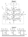
- the network 10 of coupled resonators shown in FIG. figure 1 comprises means 12 for supplying an electrical input signal Ve and means 14 for electric excitation of N coupled resonators 16 1 ,..., 16 i-1 , 16 i , 16 i + 1 , ... , 16 N using this electrical input signal Ve.
- the electrical excitation means 14 comprise, for each of these N coupled resonators 16 1 ,..., 16 i-1 , 16 i , 16 i + 1 ,..., 16 N , actuating means 18 1 , ..., 18 i-1 , 18 i , 18 i + 1 , ..., 18 N connected to the means 12 for supplying the electrical input signal for an actuation of this coupled resonator as a function of the electrical signal of input, and variable gain input amplifying means 20 1 , ..., 20 i-1 , 20 i , 20 i + 1 , ..., 20 N respectively.
- Each of these input amplification means 20 i is specific to the coupled resonator 16 i and is designed to amplify the actuation of this coupled resonator.
- the electrical excitation means 14 comprise means 22 for controlling a specific variable gain adjustment GEi of each of the input amplification means 20 i .
- gain control means are conventional and therefore will not be detailed. They are of programmable type.
- each of the input amplification means 20 i is for example a variable gain input amplifier through which each corresponding actuating means 18 i is connected to the means 12 for supplying the input electrical signal .
- the amplification means may be integrated with the actuating means.
- the actuation is differently weighted to excite differently the N coupled resonators 16 1 , ..., 16 i-1 , 16 i , 16 i + 1 , ..., 16 N of the network 10. In this way, it is possible to dynamically influence the central resonance frequency and the bandwidth of the resonator network.
- Each resonator 16 i electrically excited is for example an electromechanical resonator comprising at least one vibrating element such as a bending vibrating beam-type element, a disc-type element, vibrating plate or beam in volume or at least one nano-wire.
- electromechanical resonators type NEMS or MEMS vibrating disk In the particular example shown on the figure 1 , provided solely for illustrative and non-limiting, it is, according to the scale, electromechanical resonators type NEMS or MEMS vibrating disk.
- the electrostatic actuation means of each resonator then comprise an excitation electrode connected to the means 12 for supplying the electrical input signal Ve via an amplifier.
- the coupling of the network resonators 10 is mechanical and one-dimensional in the sense that the resonators are coupled step by step, so as to form a line of N coupled resonators excited by N electrodes 18 1 , ... , 18 i-1 , 18 i , 18 i + 1 , ..., 18 N.
- each resonator 16 i is mechanically coupled by means of mechanical structures 24, on the one hand to the resonator 16 i-1 , on the other hand to the resonator 16 i + 1 , which are its two adjacent resonators. in the network 10.
- the mechanical coupling structures 24 are for example nano / micro beams, springs, etc. In the case of a network of electric resonators of the RLC type, the coupling would be electrical and made by a component such as a capacitance or a mutual inductance.
- the resonator 16 1 can be mechanically coupled to a resonator 16 0 fixed and not excited by an electrode.
- the resonator 16 N can be mechanically coupled to a resonator 16 N + 1 fixed and not excited by an electrode. This is the recessed-recessed network configuration.
- the number N can vary from two resonators to thousands of resonators, especially in the case of NEMS resonators.
- the network 10 furthermore comprises, for each of these N coupled resonators 16 1 ,..., 16 i-1 , 16 i , 16 i + 1 ,..., 16 N , means 26 1 , ... , 26 i-1 , 26 i , 26 i + 1 , ..., 26 N detecting a reaction of each coupled resonator in response to the electrical excitation of the N coupled resonators 16 1 , ..., 16 i -1 , 16 i , 16 i + 1 , ..., 16 N by the input electrical signal Ve, and transforming this reaction into an intermediate electrical signal.
- the detection and transformation means comprise capacitive detection electrodes. Each electrode 26 i is thus placed in front of the resonator 16 i corresponding to detect the variation of the capacitance formed between it and this resonator following the mechanical vibrations of the latter. It outputs the intermediate electrical signal mentioned above.
- the capacitive detection electrodes 26 1 ,..., 26 i-1 , 26 i , 26 i + 1 ,..., 26 N are furthermore all connected at output to means for grouping the N intermediate electrical signals to form an electrical output signal Vs.
- the grouping means comprise for example a simple summator 30 to which each electrode 26 i is connected via an output amplifier 28 i variable gain specific to the coupled resonator 16 i .
- the output amplifiers 28 1 , ..., 28 i-1 , 28 i , 28 i + 1 , ..., 28 N can be connected to the control means 22 to allow a specific adjustment of their respective gains GSi.
- the output amplifiers can be replaced by amplification means integrated with the detection and transformation.
- a first possible use of this resonator network 10 relates to the bandpass filtering of a signal supplied as an input electrical signal Ve of the network. At the output, Vs then represents the filtered signal.
- a second possible application of this resonator network 10 is to provide a time base by using the network as an oscillator.
- a feedback circuit 32 connects the output of the summator 30 to the input of the network, at the means 12 for supplying the electrical input signal and instead of the signal Ve, so as to provide the electrical signal input according to the electrical output signal Vs of the resonator network 10 and thus to make the resonant network around a natural frequency.
- the figure 2 represents an equivalent mechanical model of the network of coupled resonators of the figure 1 .
- the coupling between adjacent resonators is represented by a stiffness k C.
- each modal vector corresponds to a response mode of the network having its own gain, its own bandwidth and its own resonant frequency (or pulsation).
- one of the N frequency response modes of the network 10 is activated by projecting the input signal Ve on one of the N modal vectors of the network 10; that is, by selectively adjusting the value of the N variable gains GE 1 of the amplifiers 20 1 ,..., 20 i-1 , 20 i , 20 i + 1 , ..., 20 N as a function of the components of one N modal vectors, more precisely proportionally to these components.
- This projection forces the network 10 to react as a bandpass filter on the selected mode. Consequently, only the mode corresponding to the modal vector on which the input signal Ve is projected is activated, the other modes not responding, since their modal coefficients are zero for any excitation frequency.
- the selective adjustment of the gains GEi is carried out by the control means 22.
- the central frequency and the bandwidth of the filtering produced by the resonator network 10 are adjusted by choosing one or more modes to be activated by adjusting the variable gains GEi.
- the components of these modal vectors also represent the forty-nine gain values GEi to be adjusted by the control means 22 to force the network 10 to react in the corresponding mode by projecting the operation Ve on the desired modal vector.
- the output signal Vs of the resonator network can be obtained at the output of a single resonator of the network.
- the detection electrodes 26 1 ,..., 26 i-1 , 26 i , 26 i + 1 ,..., 26 N are connected to the summator 30 via the intermediaries output amplifiers 28 1 , ..., 28 i-1 , 28 i , 28 i + 1 , ..., 28 N whose GSi gains are variable.
- the control means 22 are then designed to adjust the value of the variable gains GSi as a function of that of the gains GEi, that is to say according to the components of the modal vector selected at the input of the network of resonators. More precisely, the gain GSi of the output amplifier 28 i of the resonator 16 i is chosen equal to the gain GEi of the input amplifier 20 i of the same resonator.
- this particular setting of the gain of the output amplifiers makes it possible to amplify the overall gain at the output of the resonator array by a factor (N + 1) / 2 relative to the gain of a single resonator.
- This setting improves the signal-to-noise ratio of the resonator network compared to a single resonator and makes it more sensitive in detection.
- N 49 NEMS type resonator resonators of resonance pulse equal to 10 7 rad / s.
- the frequency response of only one of these resonators, in the case where it is not coupled to another one, is represented by the curve 40, centered around the 7 rad / s resonance pulse.
- the curve 42 represents the frequency response of the network 10 according to its first mode of operation, when the gains GEi and GSi are fixed by the control means 22 to the values of the components of the modal vector represented on FIG. figure 3a .
- the curve 44 represents the frequency response of the network 10 according to its central mode of operation, when the gains GEi and GSi are fixed by the control means 22 to the values of the components of the modal vector represented on FIG. figure 3b .
- the curve 46 represents the frequency response of the network 10 according to its last mode of operation, when the gains GEi and GSi are fixed by the control means 22 to the values of the components of the modal vector represented on FIG. figure 3c .
- the network of resonators 10 makes it possible to produce an adjustable central frequency band and bandwidth filter or oscillator by providing adjustment means that simply and precisely favor one or more or all of its modes of operation.
- the resonator array 10 described above can be used as a bandpass filter with adjustable center frequency and bandwidth.
- the input signal of the filter is the signal Ve and Vs is the filtered signal.
- the resonator array 10 may also be used as an element of an adjustable center frequency oscillator. In this application, it must be associated with a feedback circuit able to return the output signal to the input of the resonator network while ensuring a certain phase shift to fulfill the conditions of reaction necessary for the oscillation of the network.
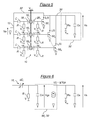
- An exemplary embodiment of an oscillator integrating a network of resonators according to an embodiment of the invention will now be detailed with reference to the figure 5 .
- the oscillator represented on the figure 5 comprises a network of resonators of the NEMS or MEMS type, for example identical to the previously described network. It then has the same reference 10.
- the resonators are excited by electrostatic actuation, using electrodes, and their displacements are measured by a capacitive detection, also using electrodes.
- each resonator 16 i is subjected to an alternating potential difference between its metal structure and the corresponding excitation electrode 18 i , which generates an oscillatory electrostatic force causing a vibration of the resonator.
- each vibration of the resonator 16 i generates a capacitance variation between its metal structure and the corresponding detection electrode 26 i .
- the input 12 of the resonator network is subjected to a sinusoidal voltage Ve modulated for each resonator 16 i by the excitation electrode 18 i whose transduction gain is variable and proportional to its bias voltage V i .
- resistors R are used for the biasing of the excitation electrodes 18 1 ,..., 18 i ,..., 18 N which are furthermore connected to the means 12 for supplying the input signal by means of FIG. intermediate of capacities C.
- each resonator 16 i is detected and modulated by the detection electrode 26 i whose transduction gain is variable and proportional to its bias voltage V i .
- This bias voltage V i is adjusted by the control means 22 to be equal to the bias voltage of the excitation electrode 18 i , so as to amplify the output of the resonator array as indicated above.
- the intermediate signal provided by the detection electrode 26 i passes through a gain stage 50 i comprising a transconductance transistor g for the supply of an intensity current i i (t) carrying the output signal.
- the oscillator represented on the figure 5 further comprises a read circuit 52.
- This read circuit comprises a load resistor Rs connected to a predetermined potential Vdd and a load capacitance Cs connected to the ground at which the output voltage Vs is measured.
- each resonator 16 i can be considered as a variable capacitance capacitor dC i oscillating at a frequency equal to that of the input signal Ve and differently polarized, the circuit connecting this resonator 16 i and its detection electrode 26 i at the load capacitance Cs and consisting of the gain stage 50 i , the adder 30 and the read circuit 52 can be modeled by an equivalent circuit shown in FIG. figure 6 .
- the assembly illustrated in FIG. figure 5 performs the function of a resonance frequency oscillator adjustable between several modes of operation.
- the presence of the capacitors C between the excitation electrodes 18 1 ,..., 18 i ,..., 18 N and the means 12 for supplying the input signal makes it possible to decouple the polarization voltages from the DC voltage excitation electrodes at the output of transistors 50 1 , ..., 50 i , ..., 50 N.
- the assembly simply performs the function of an adjustable center frequency filter.
- the above-mentioned gain stage can be realized in CMOS technology, bipolar technology or even in bi-CMOS technology.
- it is assimilated to a small field effect MOS transistor signal model. But it could just as easily be assimilated to a small bipolar transistor signal model by replacing the capacitances by resistors, the principle of calculations remaining the same.
- the central frequency of the resonator network is adjusted by selecting a particular mode by choosing a weighting of the input and output gains according to the components of a modal vector among N predefined modal vectors.
- the bandwidth of the resonator network in the selected operating mode is narrow in view of curves 42 to 46.
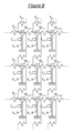
- the coupling of the resonators of the grating 10 is two-dimensional in the sense that the resonators are, on the one hand, coupled step by step by first coupling means 24 1 so as to form lines i of N coupled resonators 16 i, 1 , ..., 16 i, j , ..., 16 i, N excited by N actuating means 18 i, 1 , ..., 18 i, j , ..., 18 i, N , and, on the other hand, coupled step by step by second coupling means 24 2 so as to form columns of M coupled resonators 16 1, j , ..., 16 ⁇ , j , ..., 16 M, excited by M actuating means 18 1, j , ..., 18 i, j , ..., 18 M, j .
- the coupling 24 1 between resonators of the same line i is for example weak, so as to generate modes (which will be described as horizontal) of near central frequencies, and that (24 2 ) between resonators of the same column I am for example strong, so as to generate modes (which will be called vertical) distant central frequencies.
- the resulting resonator network 10 therefore comprises a matrix of MxN resonators 16 i, j coupled in M rows and N columns.
- these resonators are, according to the scale, electromechanical resonators type NEMS or MEMS vibrating disk.
- the actuating means 18 i, j of each resonator 16 i, j then comprise an electrostatic excitation electrode whose transmission gain GE i can be adjusted by adjusting its bias voltage using the control means 22. (not shown in this figure).
- the electrostatic excitation electrode of the actuating means 18 i, j may have the same polarization as the others and be connected to the supply means 12 of the electrical input signal via an amplification amplifier.
- variable gain input GEi, j (not shown in this figure).
- each resonator 16 i, j comprise a capacitive detection electrode for detecting the reaction of the resonator 16 i, j by measuring a variable electrical parameter (ie the capacitance between the resonator and the electrode) because of its vibrations.
- Each detection electrode 26 i, j is connected at the output to the adder 30 to form an electrical output signal Vs.
- Its transduction gain can for example be adjustable by adjusting its bias voltage using the control means 22 (FIG. not shown in this figure).
- the detection electrode 26 i, j can have the same polarization as the others and be connected to the adder 30 via a variable gain output amplifier 28 i, j (no shown in this figure) specific to the coupled resonator 16 i, j .
- the output amplifiers 28 i, j can be connected to the control means 22 to allow a specific adjustment of their respective gains GS i, j.
- each resonator 16 i, j is mechanically coupled by means of mechanical structures forming the coupling means 24 1 , on the one hand to the resonator 16 i, j-1 , on the other hand to the resonator 16 i, j + 1 , which are its two adjacent resonators in line i; each resonator 16 i, j is also mechanically coupled by means of mechanical structures forming the coupling means 24 2 , on the one hand to the resonator 16 i-1, j , on the other hand to the resonator 16 i + 1, j , which are its two adjacent resonators in column j.
- the mechanical coupling structures 24 1 and 24 2 are, for example, nano / micro beams, springs, etc. In the case of a network of RLC type electric resonators, the coupling would be electrical and made by a component such as a capacitance or a mutual inductance.
- the figure 8 represents an equivalent mechanical model of the network of coupled resonators of the figure 7 .
- the resonators are of type mass ( ⁇ ), spring (stiffness k 0 ), damping (of factor b) with two degrees of freedom.
- the coupling between adjacent resonators of the same line is represented by a stiffness k C1 and the coupling between adjacent resonators of the same column is represented by a stiffness k C2 .
- MN displacements can be defined as a matrix displacement U of the network whose components are the displacements of each of the resonator MNs.
- each modal vector corresponds to a response mode of the network having its own gain, its own bandwidth and its own resonant frequency (or pulsation).
- one of the MN frequency response modes of the network 10 by projecting the input signal Ve on one of the MN modal vectors of the network 10, that is, by selectively setting the value of the MN variable gains GE i, amplifiers 1 , 1 1 ,..., 20 i, j ,..., M, N depending on the components of one of the MN modal vectors, more precisely proportionally to these components.
- This projection forces the network 10 to react as a bandpass filter on the selected mode. Consequently, only the mode corresponding to the modal vector on which the input signal Ve is projected is activated, the other modes not responding, since their modal coefficients are zero for any excitation frequency.
- the selective adjustment of the gains GEi, j is carried out by the control means 22.
- the frequency response of only one of these resonators would be represented by the curve 40 if it were not coupled to others, this curve being centered around the 7 rad / s resonance pulse .
- this two-dimensional network it is seen that it is possible to obtain either a network of broad band filter resonators and adjustable central frequency according to M different vertical modes or a network of narrow band resonators and adjustable central frequency according to MN different modes.
- the grating as an oscillator, it is not necessary to provide a high gain in the feedback electronics to maintain the oscillations, since the output signal is already greatly amplified in the case of an oscillator. number of resonators used in the network.
- network-based resonant sensors such as those described above for designing mass, acceleration, pressure or other sensors.
- the same principle used in single-resonator sensors can be applied, but having a larger measurement signal by a factor proportional to the number of resonators, thus improving the signal-to-noise ratio and thereby facilitating the detection of very low variations.
- the resonator network is robust to the resonant resonant frequency dispersion since the standard deviation of this dispersion is also inversely proportional to the square root of the number of resonators.
- the resonator network can remain very small, too, especially of smaller size than known MEMS type resonators. It can also be achieved by a cointegration technique allowing the simultaneous realization of resonators and electrical components.
- the resonators are not necessarily made in NEMS / MEMS technology. They can also be made from quartz electromechanical resonators other than NEMS / MEMS or by circuits of passive electrical components RLC.
Abstract
Description
La présente invention concerne un réseau de résonateurs couplés comportant des moyens de fourniture d'un signal électrique d'entrée et des moyens d'excitation électrique de N résonateurs couplés du réseau à l'aide de ce signal électrique d'entrée. Elle concerne également un filtre passe-bande pouvant par exemple être utilisé en tant que filtre RF (pour Radio Fréquence) et un oscillateur comportant un tel réseau de résonateurs couplés.The present invention relates to a network of coupled resonators comprising means for supplying an electrical input signal and electrical excitation means for N resonators coupled to the network by means of this input electrical signal. It also relates to a bandpass filter that can for example be used as an RF (Radio Frequency) filter and an oscillator comprising such a network of coupled resonators.
Elle s'applique notamment au domaine des télécommunications, pour la conception de filtres sélectifs, ou plus généralement au domaine des équipements électroniques, pour la conception d'oscillateurs formant des bases de temps pour cadencer une unité de calcul ou pour assurer une démodulation de signaux.It applies in particular to the field of telecommunications, for the design of selective filters, or more generally to the field of electronic equipment, for the design of oscillators forming time bases for clocking a computing unit or for demodulating signals. .
Un résonateur excitable par un signal électrique est en effet un dispositif électrique ou électromécanique défini principalement par sa fréquence de résonance f0 et son facteur de qualité Q lié aux pertes énergétiques du résonateur. La fréquence de résonance et le facteur de qualité dépendent des paramètres géométriques et de la nature des matériaux utilisés dans le cas d'un résonateur électromécanique, ou des valeurs de ses composants de type R, L ou C dans le cas d'un résonateur électrique. Un tel résonateur peut donc être utilisé en boucle ouverte pour réaliser un filtrage passe-bande autour de sa fréquence de résonance, la bande passante étant d'autant plus étroite que le facteur de qualité est élevé. Il peut aussi être utilisé en boucle fermée, à l'aide d'un circuit électronique de rétroaction assurant son oscillation en générant, à partir du signal fourni par le résonateur, un signal capable d'exciter le résonateur sur sa fréquence de résonance f0.A resonator excitable by an electrical signal is in fact an electrical or electromechanical device defined mainly by its resonance frequency f 0 and its Q quality factor related to the energy losses of the resonator. The resonance frequency and the quality factor depend on the geometrical parameters and the nature of the materials used in the case of an electromechanical resonator, or the values of its components of R, L or C type in the case of an electric resonator . Such a resonator can therefore be used in an open loop to perform bandpass filtering around its resonant frequency, the bandwidth being all the more narrow as the quality factor is high. It can also be used in a closed loop, using a feedback electronic circuit ensuring its oscillation by generating, from the signal supplied by the resonator, a signal capable of exciting the resonator on its resonance frequency f 0 .
Un réseau de résonateurs couplés est formé de plusieurs résonateurs couplés entre eux mécaniquement (dans le cas de résonateurs électromécaniques) ou électriquement (dans le cas de résonateurs électriques) de sorte que l'excitation de l'un d'entre eux provoque la vibration mécanique ou l'oscillation électrique de l'ensemble des résonateurs couplés ayant au moins un degré de liberté dans ce réseau. Ces réseaux de résonateurs couplés permettent d'envisager des fonctions de traitement de signaux présentant une meilleure puissance et de meilleures performances que lorsque l'on utilise un résonateur seul. Par exemple, utilisés pour former des filtres, ils permettent d'obtenir une bande passante élargie.A network of coupled resonators is formed of several resonators mechanically coupled (in the case of electromechanical resonators) or electrically (in the case of electric resonators) so that the excitation of one of them causes the mechanical vibration or the electrical oscillation of the set of coupled resonators having at least one degree of freedom in this network. These coupled resonator networks make it possible to envisage signal processing functions having better power and better performance than when using a resonator alone. For example, used to form filters, they make it possible to obtain an enlarged bandwidth.
Différents types de résonateurs excitables par un signal électrique sont connus et peuvent être utilisés pour former un tel réseau. Par exemple, les résonateurs à ondes acoustiques de surface, dits résonateurs SAW (de l'Anglais « Surface Acoustic Wave »), à ondes acoustiques de volume, dits résonateurs BAW (de l'Anglais « Bulk Acoustic Wave »), ou à cristal de quartz sont des résonateurs électromécaniques dont les principaux inconvénients sont leur taille relativement importante et leur implémentation hors puce électronique entraînant des connexions qui introduisent des valeurs parasites et du bruit et qui les rendent encombrants.Different types of resonators excitable by an electrical signal are known and can be used to form such a network. For example, surface acoustic wave resonators, SAW resonators (of the English "Surface Acoustic Wave"), acoustic wave volume, so-called BAW resonators (of the English "Bulk Acoustic Wave"), or quartz crystal are electromechanical resonators whose main drawbacks are their relatively large size and their off-chip implementation resulting in connections that introduce parasitic values and noise and which make it bulky.
Pour résoudre ces problèmes d'encombrement et d'intégration, il est préférable d'utiliser des résonateurs électromécaniques de type NEMS (de l'Anglais « Nano Electro Mechanical Systems ») ou MEMS (de l'Anglais « Micro Electro Mechanical Systems »), ou des résonateurs électriques de type R, L, C offrant la possibilité de fabriquer le réseau de résonateurs collectivement par des techniques issues de la microélectronique. Les résonateurs NEMS/MEMS en particulier présentent un encombrement réduit et une faible consommation. Ils permettent en outre d'obtenir des hautes fréquences de résonance et des facteurs de qualité très élevés. Enfin, ils sont simples à réaliser et peuvent être intégrés avec des éléments électroniques de traitement de données sur une même puce ou carte électronique.To solve these problems of size and integration, it is preferable to use electromechanical resonators type NEMS (English "Nano Electro Mechanical Systems") or MEMS (English "Micro Electro Mechanical Systems") , or R, L, C type electric resonators offering the possibility of fabricating the resonator array collectively by microelectronic techniques. NEMS / MEMS resonators in particular have a small footprint and low power consumption. They also make it possible to obtain high resonance frequencies and very high quality factors. Finally, they are simple to implement and can be integrated with electronic data processing elements on the same chip or electronic card.
Concrètement, le couplage mécanique entre deux résonateurs NEMS/MEMS est réalisé à l'aide d'un pont mécanique plus ou moins rigide, tandis que le couplage électrique entre deux résonateurs électriques R, L, C peut être réalisé à l'aide d'une capacité ou d'une inductance mutuelle.Specifically, the mechanical coupling between two NEMS / MEMS resonators is achieved using a more or less rigid mechanical bridge, while the electrical coupling between two electric resonators R, L, C can be achieved using a capacity or mutual inductance.
Le document de
Ce réseau est constitué de résonateurs électromécaniques de type plaque couplés mécaniquement dont le signal de sortie est relié à un étage de gain. Le signal de sortie de cet étage de gain est lui-même rebouclé sur le système d'actionnement commun à tous les résonateurs pour former un oscillateur. Cette architecture particulière en réseau permet d'obtenir un oscillateur globalement moins bruité avec une résistance motionnelle la plus faible possible.This network consists of mechanically coupled electromechanical plate resonators whose output signal is connected to a gain stage. The output signal of this gain stage is itself looped back to the actuation system common to all the resonators to form an oscillator. This particular network architecture makes it possible to obtain a globally less noisy oscillator with the lowest possible motional resistance.
Le document de
Ce réseau disposé en matrice est constitué de résonateurs électromécaniques de type disque couplés mécaniquement par des ponts dont les longueurs s'expriment en fractions de la longueur d'onde de résonance. Comme précédemment, cette architecture permet d'obtenir une faible résistance motionnelle. Elle permet en outre de supprimer une partie des modes résonants non souhaités du réseau.This matrix array consists of electromechanical disk type resonators mechanically coupled by bridges whose lengths are expressed as fractions of the resonant wavelength. As before, this architecture makes it possible to obtain a low emotional resistance. It also makes it possible to suppress some of the undesired resonant modes of the network.
Néanmoins, ces architectures ne permettent pas d'ajuster la fréquence centrale ou la bande passante du résonateur global, la configuration de l'actionnement des résonateurs étant fixée à l'avance par l'emplacement des actionneurs pour accentuer au moins un des modes. Toutefois ceci est fait sans supprimer complètement les autres modes qui sont simplement fortement atténués. Ainsi dans une application de base de temps en présence de fortes dispersions sur les fréquences de résonance de chaque résonateur, il est impossible avec les architectures précitées de corriger efficacement ces dispersions.Nevertheless, these architectures do not make it possible to adjust the central frequency or the bandwidth of the overall resonator, the configuration of the actuation of the resonators being fixed in advance by the location of the actuators to accentuate at least one of the modes. However this is done without completely deleting the other modes which are simply strongly attenuated. Thus in a time base application in the presence of strong dispersions on the resonant frequencies of each resonator, it is impossible with the aforementioned architectures to effectively correct these dispersions.
Une architecture permettant d'ajuster la bande passante d'un filtre utilisant un réseau de résonateurs couplés est décrite dans le document de
Plus précisément, ce filtre est constitué d'un réseau de quatre résonateurs couplés en série dont seul le premier est connecté à une électrode d'excitation et seul le dernier est connecté à une électrode de détection. En commutant en outre l'un ou plusieurs des résonateurs couplés du réseau sur une tension de polarisation prédéterminée on peut sélectionner un mode de fonctionnement particulier du filtre parmi trois modes possibles dont un mode en bande large, un mode en bande basse et un mode en bande haute. Cet ajustement est cependant assez sommaire et peu souple.More precisely, this filter consists of an array of four series-coupled resonators of which only the first is connected to an excitation electrode and only the last is connected to a detection electrode. By further switching one or more of the network coupled resonators to a predetermined bias voltage a particular operating mode of the filter can be selected from among three possible modes, including a wide band mode, a low band mode and a mode. high band. This adjustment, however, is rather summary and not very flexible.
Il peut ainsi être souhaité de prévoir un réseau de résonateurs couplés qui permette de s'affranchir des problèmes et contraintes précités.It may thus be desirable to provide a network of coupled resonators that makes it possible to overcome the aforementioned problems and constraints.
L'invention a donc pour objet un réseau de résonateurs couplés comportant des moyens de fourniture d'un signal électrique d'entrée et des moyens d'excitation électrique de N résonateurs couplés du réseau à l'aide de ce signal électrique d'entrée. Dans ce réseau de résonateurs couplés, les moyens d'excitation électrique comportent :
- pour chacun de ces N résonateurs couplés :
- ■ des moyens d'actionnement raccordés aux moyens de fourniture du signal électrique d'entrée pour un actionnement de ce résonateur couplé en fonction du signal électrique d'entrée, et
- ■ des moyens d'amplification d'entrée à gain variable de l'actionnement de ce résonateur couplé propres à ce résonateur couplé,
- des moyens de commande d'un réglage spécifique du gain variable de chacun des moyens d'amplification d'entrée.
- for each of these coupled N resonators:
- Actuating means connected to the means for supplying the electrical input signal for an actuation of this coupled resonator as a function of the electrical input signal, and
- Variable-gain input amplification means for actuating this coupled resonator specific to this coupled resonator,
- means for controlling a specific adjustment of the variable gain of each of the input amplification means.
Ainsi, en pondérant différemment les excitations des différents résonateurs du réseau, il est possible de sélectionner une fréquence centrale de résonance et la bande passante du réseau de résonateurs. En disposant en outre de moyens pour régler dynamiquement cette pondération à l'aide de moyens d'amplification à gains variables commandés, on obtient un réseau de résonateurs dont la fréquence centrale de résonance et la bande passante sont réglables dynamiquement. Grâce à ce simple réglage, il est alors possible d'envisager des applications performantes de filtrage à bande passante ajustable ou d'oscillation à résonance ajustable.Thus, by weighting differently the excitations of the different resonators of the network, it is possible to select a central resonance frequency and the bandwidth of the resonator network. By additionally having means for dynamically adjusting this weighting using controlled variable gain amplification means, an array of resonators is obtained whose central resonant frequency and bandwidth are dynamically adjustable. With this simple adjustment, it is then possible to consider efficient applications of filtering adjustable bandwidth or adjustable resonance oscillation.
De façon optionnelle, chaque résonateur comporte au moins un élément vibrant choisi parmi l'un des éléments de l'ensemble constitué d'un élément de type poutre vibrant en flexion, d'un élément de type disque, plaque ou poutre vibrant en volume et d'au moins un nano fil.Optionally, each resonator comprises at least one vibrating element chosen from one of the elements of the assembly consisting of a bending vibrating beam-type element, a disk-like element, a plate or vibrating beam in volume and at least one nanowire.
De façon optionnelle également, les résonateurs couplés sont des résonateurs électromécaniques de type NEMS ou MEMS et les moyens d'actionnement et d'amplification d'entrée à gain variable de chacun desdits N résonateurs couplés comportent une électrode d'excitation électrostatique dont la tension de polarisation est réglable par les moyens de commande.Also optionally, the coupled resonators are electromechanical resonators of NEMS or MEMS type and the variable gain input actuation and amplification means of each of said N coupled resonators comprise an electrostatic excitation electrode whose voltage of polarization is adjustable by the control means.
De façon optionnelle également, ce réseau de résonateurs étant générateur de N modes de résonance différents à N fréquences modales différentes, tout signal vectoriel résultant de N signaux électriques fournis par lesdits N résonateurs couplés en réponse à une excitation à l'aide du signal électrique d'entrée pouvant être exprimé en tant que combinaison linéaire de N vecteurs modaux prédéterminés exprimant chacun la réponse desdits N résonateurs couplés dans l'un des N modes de résonance, les moyens de commande sont conçus pour régler sélectivement la valeur des N gains variables des moyens d'amplification d'entrée en fonction des composantes de l'un des N vecteurs modaux, notamment proportionnellement à ces composantes.Also optionally, this resonator network being a generator of N different resonance modes with N different modal frequencies, any vector signal resulting from N electrical signals supplied by said N resonators coupled in response to an excitation using the electrical signal of The input may be expressed as a linear combination of N predetermined modal vectors each expressing the response of said N coupled resonators in one of the N resonance modes, the control means are adapted to selectively adjust the value of the N variable gains of the means. of input amplification as a function of the components of one of the N modal vectors, especially in proportion to these components.
De façon optionnelle également, un réseau de résonateurs couplés selon l'invention peut en outre comporter :
- pour chacun de ces N résonateurs couplés, des moyens de détection d'une réaction de ce résonateur couplé, en réponse à l'excitation électrique des N résonateurs couplés par le signal électrique d'entrée, et de transformation de cette réaction en un signal électrique intermédiaire,
- des moyens de regroupement des signaux électriques intermédiaires pour former un signal électrique de sortie,
- for each of these N coupled resonators, means for detecting a reaction of this coupled resonator, in response to the electrical excitation of the N resonators coupled by the electrical input signal, and of transforming this reaction into an electrical signal intermediate,
- means for grouping the intermediate electric signals to form an electrical output signal,
De façon optionnelle également, les moyens de détection et de transformation et les moyens d'amplification de sortie à gain variable de chacun desdits N résonateurs couplés comportent une électrode de détection capacitive dont la tension de détection est réglable par les moyens de commande.Also optionally, the detection and transformation means and the variable gain output amplification means of each of said N coupled resonators comprise a capacitive detection electrode whose detection voltage is adjustable by the control means.
De façon optionnelle également, les moyens de commande sont conçus pour fixer la valeur des gains variables des moyens d'amplification de sortie de en fonction des composantes du vecteur modal sélectionné pour fixer la valeur des gains variables des moyens d'amplification d'entrée, notamment proportionnellement à ces composantes.Also optionally, the control means are adapted to set the value of the variable gains of the output amplification means according to the components of the selected modal vector to set the value of the variable gains of the input amplification means, in particular in proportion to these components.
De façon optionnelle également, un réseau de résonateurs couplés selon l'invention peut en outre comporter une charge capacitive connectée aux moyens de regroupement pour recevoir un courant transmis par ces moyens de regroupement et configurée pour que la tension à ses bornes soit représentative du signal électrique de sortie.Optionally also, a network of coupled resonators according to the invention may further comprise a capacitive load connected to the grouping means for receiving a current transmitted by these grouping means and configured so that the voltage at its terminals is representative of the electrical signal. Release.
L'invention a également pour objet un filtre passe-bande à fréquence centrale ajustable comportant un réseau de résonateurs couplés tel que défini précédemment, conçu pour recevoir un signal à filtrer en tant que signal électrique d'entrée du réseau de résonateurs.The subject of the invention is also an adjustable central frequency band-pass filter comprising an array of coupled resonators as defined above, designed to receive a signal to be filtered as an electrical input signal of the resonator network.
L'invention a également pour objet un oscillateur à fréquence d'oscillation ajustable comportant un réseau de résonateurs couplés tel que défini précédemment et un circuit de rétroaction pour la fourniture du signal électrique d'entrée en fonction du signal électrique de sortie du réseau de résonateurs.The subject of the invention is also an oscillator with an adjustable oscillation frequency comprising an array of coupled resonators as defined above and a feedback circuit for supplying the electrical input signal as a function of the electrical output signal of the resonator network. .
L'invention sera mieux comprise à l'aide de la description qui va suivre, donnée uniquement à titre d'exemple et faite en se référant aux dessins annexés dans lesquels :
- la
figure 1 représente schématiquement la structure générale d'un réseau de résonateurs couplés à une dimension selon un premier mode de réalisation de l'invention, - la
figure 2 représente un modèle mécanique équivalent du réseau de résonateurs couplés de lafigure 1 , - les
figures 3a, 3b, 3c illustrent graphiquement des valeurs de gains applicables par des moyens de commande du réseau de résonateurs couplés de lafigure 1 , - les
figures 4a et 4b illustrent graphiquement différentes réponses fréquentielles possibles du réseau de résonateurs couplés de lafigure 1 , - la
figure 5 représente schématiquement la structure générale d'un oscillateur selon un mode de réalisation de l'invention, - la
figure 6 représente schématiquement un circuit équivalent d'un circuit de lecture d'un signal de sortie fourni par l'oscillateur de lafigure 5 , - la
figure 7 représente schématiquement la structure générale d'un réseau de résonateurs couplés à deux dimensions selon un second mode de réalisation de l'invention, - la
figure 8 représente un modèle mécanique équivalent du réseau de résonateurs couplés de lafigure 7 , et - la
figure 9 illustre graphiquement différentes réponses fréquentielles possibles du réseau de résonateurs couplés de lafigure 7 .
- the
figure 1 schematically represents the general structure of a network of resonators coupled to a dimension according to a first embodiment of the invention, - the
figure 2 represents an equivalent mechanical model of the network of coupled resonators of thefigure 1 , - the
Figures 3a, 3b, 3c graphically illustrate applicable gain values by control means of the coupled resonator network of thefigure 1 , - the
Figures 4a and 4b graphically illustrate different possible frequency responses of the coupled resonator network of thefigure 1 , - the
figure 5 schematically represents the general structure of an oscillator according to one embodiment of the invention, - the
figure 6 schematically represents an equivalent circuit of a read circuit of an output signal provided by the oscillator of thefigure 5 , - the
figure 7 schematically represents the general structure of a network of two-dimensional coupled resonators according to a second embodiment of the invention, - the
figure 8 represents an equivalent mechanical model of the network of coupled resonators of thefigure 7 , and - the
figure 9 graphically illustrates different possible frequency responses of the coupled resonator network of thefigure 7 .
Le réseau 10 de résonateurs couplés représenté sur la
Les moyens d'excitation électrique 14 comportent, pour chacun de ces N résonateurs couplés 161, ..., 16i-1, 16i, 16i+1, ..., 16N, des moyens d'actionnement 181, ..., 18i-1, 18i, 18i+1, ..., 18N raccordés aux moyens 12 de fourniture du signal électrique d'entrée pour un actionnement de ce résonateur couplé en fonction du signal électrique d'entrée, et des moyens d'amplification d'entrée à gain variable 201, ..., 20i-1, 20i, 20i+1, ..., 20N respectifs. Chacun de ces moyens d'amplification d'entrée à gain variable 20i est propre au résonateur couplé 16i et est conçu pour amplifier l'actionnement de ce résonateur couplé.The electrical excitation means 14 comprise, for each of these N coupled
En outre, les moyens d'excitation électrique 14 comportent des moyens 22 de commande d'un réglage spécifique du gain variable GEi de chacun des moyens d'amplification d'entrée 20i. Ces moyens de commande de gain sont classiques et ne seront donc pas détaillés. Ils sont de type programmable.In addition, the electrical excitation means 14 comprise means 22 for controlling a specific variable gain adjustment GEi of each of the input amplification means 20 i . These gain control means are conventional and therefore will not be detailed. They are of programmable type.
Comme illustré sur la
Ainsi, en agissant sur les différentes valeurs de gains GEi, l'actionnement est différemment pondéré pour exciter différemment les N résonateurs couplés 161, ..., 16i-1, 16i, 16i+1, ..., 16N du réseau 10. De cette façon, il est possible d'influer dynamiquement sur la fréquence centrale de résonance et sur la bande passante du réseau de résonateurs.Thus, by acting on the different values of gains GEi, the actuation is differently weighted to excite differently the N coupled
Chaque résonateur 16i excité électriquement est par exemple un résonateur électromécanique comportant au moins un élément vibrant tel qu'un élément de type poutre vibrant en flexion, un élément de type disque, plaque ou poutre vibrant en volume ou au moins un nano fil.Each
Dans l'exemple particulier illustré sur la
Dans cet exemple particulier également, le couplage des résonateurs du réseau 10 est mécanique et unidimensionnel dans le sens où les résonateurs sont couplés de proche en proche, de manière à former une ligne de N résonateurs couplés excités par N électrodes 181, ..., 18i-1, 18i, 18i+1, ..., 18N. En d'autres termes, chaque résonateur 16i est couplé mécaniquement à l'aide de structures mécaniques 24, d'une part au résonateur 16i-1, d'autre part au résonateur 16i+1, qui sont ses deux résonateurs adjacents dans le réseau 10. Les structures mécaniques de couplage 24 sont par exemple des nano/micro poutres, des ressorts, etc. Dans le cas d'un réseau de résonateurs électriques de type RLC, le couplage serait électrique et réalisé par un composant tel qu'une capacité ou une inductance mutuelle.In this particular example also, the coupling of the
Aux extrémités du réseau 10, différentes conditions peuvent être envisagées, telles que celles fournissant un réseau de type encastré-encastré, encastré-libre, libre-libre, en cycle, etc. Parmi celles-ci, le résonateur 161 peut être couplé mécaniquement à un résonateur 160 fixe et non excité par une électrode. De même, le résonateur 16N peut être couplé mécaniquement à un résonateur 16N+1 fixe et non excité par une électrode. Il s'agit alors de la configuration de réseau encastré-encastré.At the ends of the
Enfin, le nombre N peut varier de deux résonateurs jusqu'à des milliers de résonateurs, notamment dans le cas de résonateurs NEMS.Finally, the number N can vary from two resonators to thousands of resonators, especially in the case of NEMS resonators.
Le réseau 10 comporte en outre respectivement, pour chacun de ces N résonateurs couplés 161, ..., 16i-1, 16i, 16i+1, ..., 16N, des moyens 261, ..., 26i-1, 26i, 26i+1, ..., 26N de détection d'une réaction de chaque résonateur couplé en réponse à l'excitation électrique des N résonateurs couplés 161, ..., 16i-1, 16i, 16i+1, ..., 16N par le signal électrique d'entrée Ve, et de transformation de cette réaction en un signal électrique intermédiaire. Dans l'exemple particulier illustré sur la
Les électrodes de détection capacitive 261, ..., 26i-1, 26i, 26i+1, ..., 26N sont en outre toutes reliées en sortie à des moyens de regroupement des N signaux électriques intermédiaires pour former un signal électrique de sortie Vs. Les moyens de regroupement comportent par exemple un simple sommateur 30 auquel chaque électrode 26i est reliée par l'intermédiaire d'un amplificateur de sortie 28i à gain variable propre au résonateur couplé 16i.The
Comme les amplificateurs d'entrée 201, ..., 20i-1, 20i, 20i+1, ..., 20N, les amplificateurs de sortie 281, ..., 28i-1, 28i, 28i+1, ..., 28N peuvent être reliés aux moyens de commande 22 pour permettre un réglage spécifique de leurs gains GSi respectifs.As the
De même, dans un autre mode de réalisation, par exemple celui qui sera détaillé en référence à la
Une seconde application possible de ce réseau de résonateurs 10 concerne la fourniture d'une base de temps par l'utilisation du réseau en tant qu'oscillateur. Pour ce faire, un circuit de rétroaction 32 relie la sortie du sommateur 30 à l'entrée du réseau, au niveau des moyens 12 de fourniture du signal électrique d'entrée et à la place du signal Ve, de manière à fournir le signal électrique d'entrée en fonction du signal électrique de sortie Vs du réseau de résonateurs 10 et à rendre ainsi le réseau résonant autour d'une fréquence propre.A second possible application of this
La
Conformément à l'invention, à l'aide d'un même signal d'entrée Ve oscillant à une fréquence ω, il est possible d'appliquer individuellement une excitation d'amplitude spécifique à chacun des N résonateurs 161, ..., 16i-1, 16i, 16i+1, ..., 16N en réglant les valeurs de gains GEi.According to the invention, using the same input signal Ve oscillating at a frequency ω, it is possible to individually apply a specific amplitude excitation to each of the N resonators 16 1 , ..., 16 i-1 , 16 i , 16 i + 1 , ..., 16 N by setting the gain values GEi.
Dans le modèle mécanique de la 
On montre, par une approche modale, que la réponse vectorielle U des N résonateurs couplés peut s'exprimer comme une combinaison linéaire de N réponses vectorielles modales Un, dits vecteurs modaux, dont les composantes ![]()

![]()
On notera que les vecteurs modaux Un ainsi définis forment une base orthogonale pour le produit scalaire suivant : 
En effet, on vérifie que selon ce produit scalaire, 〈Un |Un' 〉 = 0 ⇔ n ≠ n' et 
La composante de déplacement ui du résonateur 16i peut donc s'écrire comme une combinaison linéaire des N composantes modales correspondant au résonateur 16i : 
On montre également que chaque vecteur modal correspond à un mode de réponse du réseau ayant son propre gain, sa propre bande passante et sa propre fréquence (ou pulsation) de résonance. En projetant l'équation matricielle définie précédemment sur la base constituée de ces vecteurs modaux, il est aisé de retrouver les fonctions de transfert Gn (ω) et les pulsations de résonance ω n correspondant à chaque mode : 

Ainsi, on observe que pour un réseau unidimensionnel de N résonateurs couplés 161, ..., 16i-1, 16i, 16i+1, ..., 16N à un degré de liberté, auxquels sont ajoutés, aux deux extrémités, deux résonateurs fixes couplés respectivement aux résonateurs 161 et 16N, il y a N fréquences de résonances distinctes dans l'intervalle 
Selon le modèle représenté sur la
Par analogie, dans un mode de réalisation de l'invention, on active l'un des N modes de réponse fréquentielle du réseau 10 en projetant le signal d'entrée Ve sur l'un des N vecteurs modaux du réseau 10, c'est-à-dire en réglant sélectivement la valeur des N gains variables GEi des amplificateurs 201, ..., 20i-1, 20i, 20i+1, ..., 20N en fonction des composantes de l'un des N vecteurs modaux, plus précisément proportionnellement à ces composantes. Cette projection force le réseau 10 à réagir comme un filtre passe-bande sur le mode sélectionné. Par conséquent, seul le mode correspondant au vecteur modal sur lequel est projeté le signal d'entrée Ve est activé, les autres modes ne répondant pas, étant donné que leurs coefficients modaux sont nuls pour n'importe quelle fréquence d'excitation. Le réglage sélectif des gains GEi est réalisé par les moyens de commande 22.By analogy, in one embodiment of the invention, one of the N frequency response modes of the
Plus généralement, selon l'invention, on ajuste la fréquence centrale et la bande passante du filtrage réalisé par le réseau de résonateurs 10 en choisissant un ou plusieurs modes à activer grâce au réglage des gains variables GEi.More generally, according to the invention, the central frequency and the bandwidth of the filtering produced by the
Les
Les composantes de ces vecteurs modaux représentent également les quarante-neuf valeurs de gains GEi à régler par les moyens de commande 22 pour forcer le réseau 10 à réagir dans le mode correspondant par projection de l'actionnement Ve sur le vecteur modal souhaité.The components of these modal vectors also represent the forty-nine gain values GEi to be adjusted by the control means 22 to force the
Lorsqu'un mode particulier est sélectionné par réglage des gains d'entrée GEi en fonction des composantes du vecteur modal correspondant, le signal de sortie Vs du réseau de résonateurs peut être obtenu en sortie d'un seul résonateur du réseau. Avantageusement, il est préférable de regrouper les sorties de tous les résonateurs du réseau 10 à l'aide du sommateur 30 pour tirer profit de l'ensemble des réponses, de manière à élever l'amplitude du signal de sortie Vs et réduire l'impédance du réseau de résonateurs.When a particular mode is selected by adjusting the input gains GEi according to the components of the corresponding modal vector, the output signal Vs of the resonator network can be obtained at the output of a single resonator of the network. Advantageously, it is preferable to group the outputs of all the resonators of the
Mais si ce regroupement est réalisé directement par connexion des électrodes de détection 261, ..., 26i-1, 26i, 26i+1, ..., 26N au sommateur 30, on obtient : 
Un tel regroupement n'est pas exploitable parce que le signal de sortie Vs est nul pour les modes pairs et décroissant en fonction de n pour les modes impairs.Such a grouping is not exploitable because the output signal Vs is zero for the even and decreasing modes as a function of n for the odd modes.
Selon un mode de réalisation de l'invention, les électrodes de détection 261, ..., 26i-1, 26i, 26i+1, ..., 26N sont reliées au sommateur 30 par l'intermédiaire des amplificateurs de sortie 281, ..., 28i-1, 28i, 28i+1, ..., 28N dont les gains GSi sont variables. Les moyens de commande 22 sont alors conçus pour régler la valeur des gains variables GSi en fonction de celle des gains GEi, c'est-à-dire en fonction des composantes du vecteur modal sélectionné en entrée du réseau de résonateurs. Plus précisément, le gain GSi de l'amplificateur de sortie 28i du résonateur 16i est choisi égal au gain GEi de l'amplificateur d'entrée 20i de ce même résonateur.According to one embodiment of the invention, the
En utilisant la propriété d'orthogonalité (équation 4) du produit scalaire défini précédemment, on obtient alors en sortie : 
Ainsi, on observe que ce réglage particulier des gains des amplificateurs de sortie permet d'amplifier le gain global en sortie du réseau de résonateurs d'un facteur (N+1)/2 par rapport au gain d'un seul résonateur. Ce réglage améliore le rapport signal sur bruit du réseau de résonateurs par rapport à un seul résonateur et le rend plus sensible en détection.Thus, it is observed that this particular setting of the gain of the output amplifiers makes it possible to amplify the overall gain at the output of the resonator array by a factor (N + 1) / 2 relative to the gain of a single resonator. This setting improves the signal-to-noise ratio of the resonator network compared to a single resonator and makes it more sensitive in detection.
La
La courbe 42 représente la réponse fréquentielle du réseau 10 selon son premier mode de fonctionnement, lorsque les gains GEi et GSi sont fixés par les moyens de commande 22 aux valeurs des composantes du vecteur modal représenté sur la
La courbe 44 représente la réponse fréquentielle du réseau 10 selon son mode central de fonctionnement, lorsque les gains GEi et GSi sont fixés par les moyens de commande 22 aux valeurs des composantes du vecteur modal représenté sur la
Enfin, la courbe 46 représente la réponse fréquentielle du réseau 10 selon son dernier mode de fonctionnement, lorsque les gains GEi et GSi sont fixés par les moyens de commande 22 aux valeurs des composantes du vecteur modal représenté sur la
On remarque que le gain global du réseau de résonateur 10 dans chacun de ses modes de fonctionnement est largement supérieur à celui d'un seul résonateur, comme prévu par l'équation (10).Note that the overall gain of the
Selon un autre fonctionnement possible du réseau de résonateurs 10 illustré sur la 
Il apparaît donc clairement que le réseau de résonateurs 10 permet de réaliser un filtre ou un oscillateur à fréquence centrale et à bande passante ajustables en prévoyant des moyens de réglage favorisant simplement et précisément un ou plusieurs ou tous ses modes de fonctionnement.It therefore clearly appears that the network of
On peut d'ailleurs augmenter le nombre de modes de fonctionnement du réseau en augmentant le nombre N de ses résonateurs couplés à au moins un degré de liberté. Cela permet ainsi d'augmenter la finesse de l'ajustement possible de la fréquence centrale de ce réseau de résonateurs dans l'intervalle (8) précité.It is also possible to increase the number of operating modes of the network by increasing the number N of its resonators coupled to at least one degree of freedom. This thus makes it possible to increase the fineness of the possible adjustment of the central frequency of this network of resonators in the above-mentioned interval (8).
On peut aussi élargir cet intervalle en augmentant la force du couplage entre les résonateurs (facteur kC). Plus le couplage est fort, plus l'intervalle entre la fréquence centrale du premier mode et celle du dernier mode est grand, de même que l'intervalle entre fréquences centrales de modes adjacents.It is also possible to widen this interval by increasing the strength of the coupling between the resonators (factor k C ). The stronger the coupling, the greater the interval between the central frequency of the first mode and that of the last mode, as well as the interval between central frequencies of adjacent modes.
Enfin, lorsque l'on réalise concrètement un tel réseau de N résonateurs couplés, surtout lorsque les résonateurs sont de petite taille tels que des résonateurs NEMS ou MEMS, une dispersion des paramètres caractéristiques de ces résonateurs (fréquence de résonance propre et facteur de qualité) peut avoir un effet négatif sur les performances du réseau. On montre en fait qu'en jouant sur la valeur du couplage entre résonateurs, mais surtout qu'en augmentant le nombre de résonateurs couplés, on réduit sensiblement l'effet de cette dispersion sur le réseau. En fait, plus précisément, l'écart-type des fréquences de résonance propres des N résonateurs 161, ..., 16i-1, 16i, 16i+1, ..., 16N est inversement proportionnel à la racine carrée ce de nombre N. Ainsi, augmenter N permet non seulement d'améliorer la finesse de l'ajustement possible de la fréquence centrale du réseau de résonateurs, mais aussi de compenser une dispersion des paramètres caractéristiques des résonateurs.Finally, when such a network of N coupled resonators is concretely realized, especially when the resonators are of small size such as NEMS or MEMS resonators, a dispersion of the characteristic parameters of these resonators (resonance frequency and quality factor) may have a negative effect on network performance. It is shown in fact that by adjusting the value of the coupling between resonators, but especially by increasing the number of coupled resonators, the effect of this dispersion on the network is substantially reduced. In fact, more precisely, the standard deviation of the natural resonant frequencies of the N resonators 16 1 ,..., 16 i-1 , 16 i , 16 i + 1 ,..., 16 N is inversely proportional to the square root this number N. Thus, increasing N not only improves the fineness of the possible adjustment of the central frequency of the resonator network, but also compensates for a dispersion of the characteristic parameters of the resonators.
Comme indiqué précédemment, le réseau de résonateurs 10 décrit ci-dessus peut être utilisé comme filtre passe-bande à fréquence centrale et bande passante ajustables. Dans cette application, le signal d'entrée du filtre est le signal Ve et Vs est le signal filtré.As previously indicated, the
Le réseau de résonateurs 10 peut aussi être utilisé comme élément d'un oscillateur à fréquence centrale ajustable. Dans cette application, il doit être associé à un circuit de rétroaction apte à renvoyer le signal de sortie en entrée du réseau de résonateur tout en assurant un certain déphasage pour remplir les conditions de réaction nécessaires pour la mise en oscillation du réseau. Un exemple de réalisation d'oscillateur intégrant un réseau de résonateurs selon un mode de réalisation de l'invention va maintenant être détaillé en référence à la
L'oscillateur représenté sur la
L'entrée 12 du réseau de résonateurs est soumise à une tension sinusoïdale Ve modulée pour chaque résonateur 16i par l'électrode d'excitation 18i dont le gain de transduction est variable et proportionnel à sa tension de polarisation Vi. La valeur de cette tension de polarisation Vi est réglable par les moyens de commande 22 et propre à chaque résonateur 16i. En effet, du point de vue de l'actionnement électrostatique, si en outre chaque résonateur 16i est relié à un potentiel commun VDC, la différence de potentiel entre sa structure métallique et son électrode d'excitation est égale à (Vi-VDC )+Ve. En considérant les déplacements de faible amplitude, la force électrostatique s'exerçant sur le résonateur 16i prend la forme suivante : 
On voit bien d'après cette équation (11) qu'une amplification à gain variable (Vi -VDC ) est réalisée sur la tension Ve par commande externe de la valeur de la tension Vi. On peut donc régler chaque valeur de Vi pour que chaque valeur (Vi -VDC ) reproduise la valeur de la composante correspondante de l'un des vecteurs modaux du réseau de résonateur 10, de manière à régler ce dernier sur l'un de ses modes de résonance.It can be seen from this equation (11) that a variable gain amplification ( V i -V DC ) is performed on the voltage Ve by external control of the value of the voltage V i . We can therefore adjust each value of V i so that each value ( V i - V DC ) reproduces the value of the corresponding component of one of the modal vectors of the
De façon pratique, des résistances R sont utilisées pour la polarisation des électrodes d'excitation 181, ..., 18i, ..., 18N qui sont en outre reliées aux moyens 12 de fourniture du signal d'entrée par l'intermédiaire de capacités C.Practically, resistors R are used for the biasing of the
Du point de vue de la détection, la réaction de chaque résonateur 16i est détectée et modulée par l'électrode de détection 26i dont le gain de transduction est variable et proportionnel à sa tension de polarisation Vi. Cette tension de polarisation Vi est réglée par les moyens de commande 22 pour être égale à la tension de polarisation de l'électrode d'excitation 18i, de manière à amplifier la sortie du réseau de résonateurs comme indiqué précédemment. En outre, le signal intermédiaire fourni par l'électrode de détection 26i traverse un étage de gain 50i comprenant un transistor de transconductance g pour la fourniture d'un courant d'intensité ii(t) porteur du signal de sortie.From the point of view of the detection, the reaction of each
Le sommateur 30 est alors réalisé par un simple regroupement des étages de gain 50i. Il fournit un courant 
L'oscillateur représenté sur la
Ainsi, du point de vue de la détection, chaque résonateur 16i pouvant être considéré comme un condensateur à capacité variable dCi oscillant à une fréquence égale à celle du signal d'entrée Ve et différemment polarisée, le circuit reliant ce résonateur 16i et son électrode de détection 26i à la capacité de charge Cs et constitué de l'étage de gain 50i, du sommateur 30 et du circuit de lecture 52 peut être modélisé par un circuit équivalent représenté sur la
Selon le circuit équivalent, le transistor 50i de l'étage de gain et le sommateur 30 sont représentés par un premier circuit de charge capacitive d'entrée Cin reliée à la masse fournissant une tension Vgs et un second circuit générateur de courant sur la base de la tension Vgs et de la transconductance g du transistor 50i. On montre que, pour chaque transistor 50i, la fonction de transfert H reliant la tension de sortie Vs à la capacité variable dCi représentant les déplacements du résonateur 16i prend la forme suivante : 
Par conséquent, les conditions classiques de Barkhausen nécessaires pour la mise en oscillation de l'oscillateur sont vérifiées puisque la fonction de transfert H montre que la tension de sortie est proportionnelle à la capacité variable dCi du résonateur 16i pondérée par le gain (Vi-VDC ) et qu'en outre elle subit une intégration (1/jω).Consequently, the classical Barkhausen conditions necessary for the oscillation of the oscillator are verified since the transfer function H shows that the output voltage is proportional to the variable capacitance dC i of the
En connectant tous les résonateurs au circuit de charge 52 et en reliant ce circuit de charge commun à l'entrée 12 à l'aide du circuit de rétroaction 32, de sorte que Ve = Vs, l'ensemble illustré sur la
On notera que l'étage de gain précité peut être réalisé en technologie CMOS, bipolaire ou bien encore en technologie bi-CMOS. Dans l'exemple des
Dans le mode de réalisation décrit précédemment en référence aux
Pour obtenir une large bande passante telle que celle illustrée par la courbe 48 tout en ayant la possibilité de régler la fréquence centrale, une solution est donnée par le mode de réalisation illustré sur la
Dans ce second mode de réalisation, le couplage des résonateurs du réseau 10 est bidimensionnel dans le sens où les résonateurs sont, d'une part, couplés de proche en proche par des premiers moyens de couplage 241 de manière à former des lignes i de N résonateurs couplés 16i,1, ..., 16i,j, ..., 16i,N excités par N moyens d'actionnement 18i,1, ..., 18i,j, ..., 18i,N, et, d'autre part, couplés de proche en proche par des seconds moyens de couplage 242 de manière à former des colonnes j de M résonateurs couplés 161,j, ..., 16¡,j, ..., 16M,j excités par M moyens d'actionnement 181,j, ..., 18i,j, ..., 18M,j.In this second embodiment, the coupling of the resonators of the grating 10 is two-dimensional in the sense that the resonators are, on the one hand, coupled step by step by first coupling means 24 1 so as to form lines i of N coupled
Le couplage 241 entre résonateurs d'une même ligne i est par exemple faible, de manière à générer des modes (qu'on qualifiera d'horizontaux) de fréquences centrales proches, et celui (242) entre résonateurs d'une même colonne j est par exemple fort, de manière à générer des modes (qu'on qualifiera de verticaux) de fréquences centrales éloignées.The
Le réseau de résonateur 10 résultant comporte donc une matrice de MxN résonateurs 16i,j couplés en M lignes et N colonnes.The resulting
Dans l'exemple particulier illustré sur la
Chaque électrode de détection 26i,j est reliée en sortie au sommateur 30 pour former un signal électrique de sortie Vs. Son gain de transduction peut par exemple être réglable par réglage de sa tension de polarisation à l'aide des moyens de commande 22 (non représentés sur cette figure). En variante, l'électrode de détection 26i,j peut avoir la même polarisation que les autres et être reliée au sommateur 30 par l'intermédiaire d'un amplificateur de sortie à gain variable 28i,j (non représenté sur cette figure) propre au résonateur couplé 16i,j. Dans cette configuration, comme les amplificateurs d'entrée 20i,j, les amplificateurs de sortie 28i,j peuvent être reliés aux moyens de commande 22 pour permettre un réglage spécifique de leurs gains GSi,j respectifs.Each
Dans cet exemple particulier également, le couplage bidimensionnel des résonateurs du réseau 10 est mécanique. En d'autres termes, chaque résonateur 16i,j est couplé mécaniquement à l'aide de structures mécaniques formant les moyens de couplage 241, d'une part au résonateur 16i,j-1, d'autre part au résonateur 16i,j+1, qui sont ses deux résonateurs adjacents dans la ligne i ; chaque résonateur 16i,j est également couplé mécaniquement à l'aide de structures mécaniques formant les moyens de couplage 242, d'une part au résonateur 16i-1,j, d'autre part au résonateur 16i+1,j, qui sont ses deux résonateurs adjacents dans la colonne j. Les structures mécaniques de couplage 241 et 242 sont par exemple des nano/micro poutres, des ressorts, etc. Dans le cas d'un réseau de résonateurs électriques de type RLC, le couplage serait électrique et réalisé par un composant tel qu'une capacité ou une inductance mutuelle.In this particular example also, the two-dimensional coupling of the
La
Conformément à l'invention, à l'aide d'un même signal d'entrée Ve oscillant à une fréquence ω, il est possible d'appliquer individuellement une excitation d'amplitude spécifique à chacun des M.N résonateurs 161,1, ..., 16i,j, ..., 16M,N en réglant les valeurs de gains GEi,j.
Dans le modèle mécanique de la
In the mechanical model of the
On montre, par une approche modale et comme dans la situation d'un réseau unidimensionnel, que la réponse matricielle U des M.N résonateurs couplés peut s'exprimer comme une combinaison linéaire de M.N réponses matricielles modales Um,n, dites vecteurs modaux, dont les composantes ![]()

![]()
On notera que les vecteurs modaux Um,n ainsi définis forment une base orthogonale pour le produit scalaire suivant : 
En effet, on vérifie que selon ce produit scalaire, 
La composante de déplacement ui,j du résonateur 16¡,j peut donc s'écrire comme une combinaison linéaire des M.N composantes modales correspondant au résonateur 16i,j : 
On montre également que chaque vecteur modal correspond à un mode de réponse du réseau ayant son propre gain, sa propre bande passante et sa propre fréquence (ou pulsation) de résonance. En projetant l'équation matricielle définie précédemment sur la base constituée de ces vecteurs modaux, il est aisé de retrouver les fonctions de transfert G m,n (ω) et les pulsations de résonance ω m,n correspondant à chaque mode : 

Ainsi, on observe que pour un réseau bidimensionnel de M.N résonateurs couplés 161,1, ..., 16i,j, ..., 16M,N à deux degrés de liberté, auxquels sont ajoutés, aux deux extrémités, des résonateurs fixes, il y a M.N fréquences de résonances distinctes dans l'intervalle 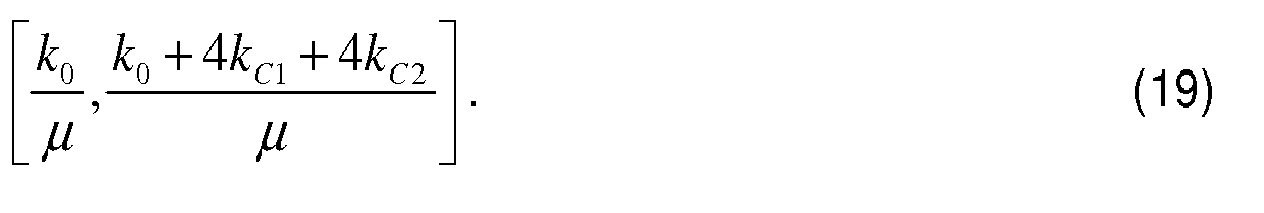
Selon le modèle représenté sur la
Par analogie, dans un mode de réalisation de l'invention, on peut activer l'un des M.N modes de réponse fréquentielle du réseau 10 en projetant le signal d'entrée Ve sur l'un des M.N vecteurs modaux du réseau 10, c'est-à-dire en fixant sélectivement la valeur des M.N gains variables GEi,j des amplificateurs 201,1, ..., 20i,j, ..., 20M,N en fonction des composantes de l'un des M.N vecteurs modaux, plus précisément proportionnellement à ces composantes. Cette projection force le réseau 10 à réagir comme un filtre passe-bande sur le mode sélectionné. Par conséquent, seul le mode correspondant au vecteur modal sur lequel est projeté le signal d'entrée Ve est activé, les autres modes ne répondant pas, étant donné que leurs coefficients modaux sont nuls pour n'importe quelle fréquence d'excitation. Le réglage sélectif des gains GEi,j est réalisé par les moyens de commande 22.By analogy, in one embodiment of the invention, it is possible to activate one of the MN frequency response modes of the
Selon un autre fonctionnement possible du réseau de résonateurs 10 illustré sur la 
La
La courbe 54 représente la réponse fréquentielle du réseau 10 selon son premier mode de fonctionnement vertical (m=1), lorsque les gains GEi,1 et GSi,1 sont fixés par les moyens de commande 22 aux valeurs de la fonction f 1,n (i).The
La courbe 56 représente la réponse fréquentielle du réseau 10 selon son deuxième mode de fonctionnement vertical (m=2), lorsque les gains GEi,2 et GSi,2 sont fixés par les moyens de commande 22 aux valeurs de la fonction f 2,n (i).The
Enfin, la courbe 58 représente la réponse fréquentielle du réseau 10 selon son dernier mode de fonctionnement vertical (m=3), lorsque les gains GEi,3 et GSi,3 sont fixés par les moyens de commande 22 aux valeurs de la fonction f 3,n (i).Finally, the
Grâce à ce réseau bidimensionnel, on voit qu'il est possible d'obtenir soit un réseau de résonateurs à filtrage large bande et à fréquence centrale ajustable selon M modes verticaux différents soit un réseau de résonateurs à bande étroite et à fréquence centrale ajustable selon M.N modes différents.Thanks to this two-dimensional network, it is seen that it is possible to obtain either a network of broad band filter resonators and adjustable central frequency according to M different vertical modes or a network of narrow band resonators and adjustable central frequency according to MN different modes.
Il apparaît clairement qu'un réseau de résonateurs tel que l'un de ceux décrits précédemment permet d'ajuster avec une bonne précision la fréquence centrale de résonance par un simple réglage de gains.It clearly appears that a network of resonators such as one of those described above makes it possible to adjust the central resonant frequency with a good accuracy by a simple gain adjustment.
En outre, en projetant l'actionnement mais aussi la détection sur un même mode de fonctionnement, on peut augmenter sensiblement l'amplitude du signal de sortie du réseau de résonateurs puisque celle-ci est alors proportionnelle au nombre de résonateurs.In addition, by projecting the operation but also the detection on the same mode of operation, it is possible to substantially increase the amplitude of the output signal of the resonator network since this is then proportional to the number of resonators.
Ainsi, dans une utilisation du réseau en tant qu'oscillateur, il n'est pas nécessaire de prévoir un gain élevé dans l'électronique de réaction pour entretenir les oscillations, puisque le signal de sortie est déjà très amplifié dans le cas d'un nombre important de résonateurs utilisés dans le réseau.Thus, in a use of the grating as an oscillator, it is not necessary to provide a high gain in the feedback electronics to maintain the oscillations, since the output signal is already greatly amplified in the case of an oscillator. number of resonators used in the network.
Dans des applications de type filtrage sélectif, il est possible d'envisager des capteurs résonants à base de réseaux tels que ceux décrits précédemment pour concevoir des capteurs de masse, d'accélération, de pression ou autre. Le même principe utilisé dans les capteurs à un seul résonateur peut être appliqué, mais en ayant un signal de mesure plus important d'un facteur proportionnel au nombre de résonateurs, améliorant ainsi le rapport signal sur bruit et facilitant par suite la détection de très faibles variations.In selective filtering type applications, it is possible to consider network-based resonant sensors such as those described above for designing mass, acceleration, pressure or other sensors. The same principle used in single-resonator sensors can be applied, but having a larger measurement signal by a factor proportional to the number of resonators, thus improving the signal-to-noise ratio and thereby facilitating the detection of very low variations.
Par ailleurs, si les bruits inhérents à chaque résonateur ne sont pas corrélés, on montre que le bruit de phase généré dans le réseau de résonateurs est réduit du fait qu'il est inversement proportionnel à la racine carrée du nombre de résonateurs.On the other hand, if the noise inherent in each resonator is not correlated, it is shown that the phase noise generated in the resonator network is reduced because it is inversely proportional to the square root of the number of resonators.
De même, le réseau de résonateurs est robuste face à la dispersion des fréquences de résonance des résonateurs puisque l'écart type de cette dispersion est lui aussi inversement proportionnel à la racine carrée du nombre de résonateurs.Similarly, the resonator network is robust to the resonant resonant frequency dispersion since the standard deviation of this dispersion is also inversely proportional to the square root of the number of resonators.
Enfin, dans le cas de résonateurs de très petite taille tels que les résonateurs de type NEMS, le réseau de résonateurs peut rester de très petite taille lui aussi, notamment de taille inférieure aux résonateurs de type MEMS connus. Il peut en outre être réalisé par une technique de co-intégration permettant la réalisation simultanée des résonateurs et des composants électriques.Finally, in the case of resonators of very small size such as NEMS type resonators, the resonator network can remain very small, too, especially of smaller size than known MEMS type resonators. It can also be achieved by a cointegration technique allowing the simultaneous realization of resonators and electrical components.
On notera par ailleurs que l'invention n'est pas limitée aux modes de réalisation décrits précédemment. Diverses modifications peuvent être apportées par l'homme de l'art aux modes de réalisation décrits ci-dessus, à la lumière de l'enseignement qui vient de lui être divulgué. Dans les revendications qui suivent, les termes utilisés ne doivent pas être interprétés comme limitant les revendications aux modes de réalisations exposés dans la présente description, mais doivent être interprétés pour y inclure tous les équivalents que les revendications visent à couvrir du fait de leur formulation et dont la prévision est à la portée de l'homme de l'art en appliquant ses connaissances générales à la mise en oeuvre de l'enseignement qui vient de lui être divulgué.Note also that the invention is not limited to the embodiments described above. Various modifications may be made by those skilled in the art to the embodiments described above, in the light of the teaching that has just been disclosed. In the following claims, the terms used are not to be interpreted as limiting the claims to the embodiments set forth in this description, but must be interpreted to include all the equivalents that the claims are intended to cover by reason of their formulation and whose prediction is within the reach of the person skilled in the art by applying his general knowledge to the implementation of the teaching which has just been disclosed to him.
Notamment, les résonateurs ne sont pas nécessairement réalisés en technologie NEMS/MEMS. Ils peuvent aussi être réalisés à base de résonateurs quartz, électromécaniques autres que NEMS/MEMS ou par des circuits de composants électriques passifs RLC.In particular, the resonators are not necessarily made in NEMS / MEMS technology. They can also be made from quartz electromechanical resonators other than NEMS / MEMS or by circuits of passive electrical components RLC.
Claims (10)
Applications Claiming Priority (1)
| Application Number | Priority Date | Filing Date | Title |
|---|---|---|---|
| FR0858383A FR2939581B1 (en) | 2008-12-09 | 2008-12-09 | NETWORK OF COUPLED RESONATORS, PASS-BAND FILTER AND OSCILLATOR. |
Publications (2)
| Publication Number | Publication Date |
|---|---|
| EP2197106A1 true EP2197106A1 (en) | 2010-06-16 |
| EP2197106B1 EP2197106B1 (en) | 2011-10-12 |
Family
ID=40810513
Family Applications (1)
| Application Number | Title | Priority Date | Filing Date |
|---|---|---|---|
| EP09177883A Active EP2197106B1 (en) | 2008-12-09 | 2009-12-03 | Array of coupled resonators, bandpass filter and oscillator |
Country Status (5)
| Country | Link |
|---|---|
| US (1) | US8253514B2 (en) |
| EP (1) | EP2197106B1 (en) |
| JP (1) | JP5585861B2 (en) |
| AT (1) | ATE528855T1 (en) |
| FR (1) | FR2939581B1 (en) |
Cited By (1)
| Publication number | Priority date | Publication date | Assignee | Title |
|---|---|---|---|---|
| FR3012805A1 (en) * | 2013-11-06 | 2015-05-08 | Commissariat Energie Atomique | MEMS / NEMS DEVICE COMPRISING AN ELECTROSTATICALLY ACTUATED RESONATOR NETWORK AND AN ADJUSTABLE FREQUENCY RESPONSE, IN PARTICULAR FOR BANDPASS FILTER |
Families Citing this family (15)
| Publication number | Priority date | Publication date | Assignee | Title |
|---|---|---|---|---|
| US7715813B2 (en) * | 2007-01-15 | 2010-05-11 | Mediatek Singapore Pte Ltd | Receiver having tunable amplifier with integrated tracking filter |
| FR2929775B1 (en) | 2008-04-08 | 2011-12-09 | Commissariat Energie Atomique | RESONANT FILTER BASED ON N / MEMS MATRIX |
| JP5414546B2 (en) | 2010-01-12 | 2014-02-12 | キヤノン株式会社 | Capacitance detection type electromechanical transducer |
| WO2011099439A1 (en) * | 2010-02-09 | 2011-08-18 | マークデバイシス株式会社 | Antiresonant frequency-varying compound resonant circuit |
| JP2012070193A (en) * | 2010-09-22 | 2012-04-05 | Nippon Dempa Kogyo Co Ltd | Oscillator |
| FR2973504B1 (en) * | 2011-03-31 | 2014-01-10 | Commissariat Energie Atomique | ELECTROMECHANICAL RESONATOR MEASURING SYSTEM, METHOD FOR MANUFACTURING SUCH A SYSTEM, AND METHOD FOR READING AT LEAST TWO ELECTROMECHANICAL RESONATORS |
| JP5990664B2 (en) | 2013-04-19 | 2016-09-14 | コチ・ウニヴェルシテシKoc Universitesi | Nanomechanical resonator array and manufacturing method thereof |
| RU2018122759A (en) | 2015-11-23 | 2019-12-26 | Анлотек Лимитед | TUNABLE FILTER |
| TWI721048B (en) * | 2016-11-28 | 2021-03-11 | 英商安諾特克有限公司 | Variable analog filter, multipole filter, and method of filtering an analog electromagnetic signal |
| TW202247602A (en) | 2017-05-24 | 2022-12-01 | 英商安諾特克有限公司 | Apparatus and method for controlling a resonator |
| US11277110B2 (en) | 2019-09-03 | 2022-03-15 | Anlotek Limited | Fast frequency switching in a resonant high-Q analog filter |
| EP4070171A1 (en) | 2019-12-05 | 2022-10-12 | Anlotek Limited | Use of stable tunable active feedback analog filters in frequency synthesis |
| US11876499B2 (en) | 2020-06-15 | 2024-01-16 | Anlotek Limited | Tunable bandpass filter with high stability and orthogonal tuning |
| EP4054076A1 (en) * | 2021-02-27 | 2022-09-07 | Anlotek Limited | Active multi-pole filter |
| TW202304153A (en) * | 2021-05-23 | 2023-01-16 | 英商安諾特克有限公司 | Multi-loop signal processing |
Citations (5)
| Publication number | Priority date | Publication date | Assignee | Title |
|---|---|---|---|---|
| US3440574A (en) * | 1966-05-05 | 1969-04-22 | Collins Radio Co | Mechanical filter having ceneral stopband characteristics |
| US6236281B1 (en) * | 1992-12-11 | 2001-05-22 | The Regents Of The University Of California | Q-controlled microresonators and tunable electronic filters using such resonators |
| US20010030489A1 (en) * | 1999-01-14 | 2001-10-18 | The Regents Of The University Of Michigan | Method and apparatus for generating a signal having at least one desired output frequency utilizing a bank of vibrating micromechanical devices |
| US20050140467A1 (en) * | 2002-08-06 | 2005-06-30 | Amy Duwel | Resonator system with a plurality of individual mechanically coupled resonators and method of making same |
| US20060125576A1 (en) * | 2004-10-18 | 2006-06-15 | Ho Gavin K | Highly tunable low-impedance capacitive micromechanical resonators, oscillators, and processes relating thereto |
Family Cites Families (11)
| Publication number | Priority date | Publication date | Assignee | Title |
|---|---|---|---|---|
| US5550516A (en) * | 1994-12-16 | 1996-08-27 | Honeywell Inc. | Integrated resonant microbeam sensor and transistor oscillator |
| CA2406518A1 (en) * | 2000-04-20 | 2001-11-01 | The Regents Of The University Of Michigan | Method and apparatus for generating a signal having at least one desired output frequency utilizing a bank of vibrating micromechanical devices |
| US6628177B2 (en) * | 2000-08-24 | 2003-09-30 | The Regents Of The University Of Michigan | Micromechanical resonator device and micromechanical device utilizing same |
| EP1573273B1 (en) * | 2002-12-10 | 2015-01-07 | Nxp B.V. | Transducer and electronic device |
| EP1432119A1 (en) * | 2002-12-17 | 2004-06-23 | Dialog Semiconductor GmbH | High quality serial resonance oscillator |
| JP2006041911A (en) * | 2004-07-27 | 2006-02-09 | Matsushita Electric Ind Co Ltd | Mems filter device and manufacturing method thereof |
| US7251466B2 (en) * | 2004-08-20 | 2007-07-31 | Xceive Corporation | Television receiver including an integrated band selection filter |
| JP4710435B2 (en) * | 2005-06-29 | 2011-06-29 | ソニー株式会社 | Microresonator, bandpass filter, semiconductor device, and communication device |
| JP4961219B2 (en) * | 2006-01-31 | 2012-06-27 | パナソニック株式会社 | Parametric resonator and filter using the same |
| JP2008103777A (en) * | 2006-10-17 | 2008-05-01 | Ritsumeikan | Micromechanical resonator |
| US7715813B2 (en) * | 2007-01-15 | 2010-05-11 | Mediatek Singapore Pte Ltd | Receiver having tunable amplifier with integrated tracking filter |
-
2008
- 2008-12-09 FR FR0858383A patent/FR2939581B1/en not_active Expired - Fee Related
-
2009
- 2009-12-03 JP JP2009275852A patent/JP5585861B2/en active Active
- 2009-12-03 EP EP09177883A patent/EP2197106B1/en active Active
- 2009-12-03 AT AT09177883T patent/ATE528855T1/en not_active IP Right Cessation
- 2009-12-07 US US12/632,239 patent/US8253514B2/en active Active
Patent Citations (5)
| Publication number | Priority date | Publication date | Assignee | Title |
|---|---|---|---|---|
| US3440574A (en) * | 1966-05-05 | 1969-04-22 | Collins Radio Co | Mechanical filter having ceneral stopband characteristics |
| US6236281B1 (en) * | 1992-12-11 | 2001-05-22 | The Regents Of The University Of California | Q-controlled microresonators and tunable electronic filters using such resonators |
| US20010030489A1 (en) * | 1999-01-14 | 2001-10-18 | The Regents Of The University Of Michigan | Method and apparatus for generating a signal having at least one desired output frequency utilizing a bank of vibrating micromechanical devices |
| US20050140467A1 (en) * | 2002-08-06 | 2005-06-30 | Amy Duwel | Resonator system with a plurality of individual mechanically coupled resonators and method of making same |
| US20060125576A1 (en) * | 2004-10-18 | 2006-06-15 | Ho Gavin K | Highly tunable low-impedance capacitive micromechanical resonators, oscillators, and processes relating thereto |
Cited By (3)
| Publication number | Priority date | Publication date | Assignee | Title |
|---|---|---|---|---|
| FR3012805A1 (en) * | 2013-11-06 | 2015-05-08 | Commissariat Energie Atomique | MEMS / NEMS DEVICE COMPRISING AN ELECTROSTATICALLY ACTUATED RESONATOR NETWORK AND AN ADJUSTABLE FREQUENCY RESPONSE, IN PARTICULAR FOR BANDPASS FILTER |
| EP2871773A1 (en) | 2013-11-06 | 2015-05-13 | Commissariat A L'energie Atomique Et Aux Energies Alternatives | MEMS/NEMS device comprising an array of electrostatic actuation resonators with adjustable frequency response, in particular for a bandpass filter |
| US9685929B2 (en) | 2013-11-06 | 2017-06-20 | Commissariat A L'energie Atomique Et Aux Energies Alternatives | MEMS/NEMS device comprising a network of electrostatically actuated resonators and having an adjustable frequency response, notably for a band-pass filter |
Also Published As
| Publication number | Publication date |
|---|---|
| FR2939581A1 (en) | 2010-06-11 |
| JP5585861B2 (en) | 2014-09-10 |
| ATE528855T1 (en) | 2011-10-15 |
| JP2010141889A (en) | 2010-06-24 |
| EP2197106B1 (en) | 2011-10-12 |
| US20100141355A1 (en) | 2010-06-10 |
| US8253514B2 (en) | 2012-08-28 |
| FR2939581B1 (en) | 2010-11-26 |
Similar Documents
| Publication | Publication Date | Title |
|---|---|---|
| EP2197106B1 (en) | Array of coupled resonators, bandpass filter and oscillator | |
| EP2796884B1 (en) | Microelectromechanical and/or nanoelectromechanical structure with ajustable quality factor | |
| EP2691742B1 (en) | Measuring system having electromechanical resonators, method for manufacturing such a system, and method for reading at least two resonators | |
| EP1660890B1 (en) | Accelerometer with reduced extraneous vibrations owing to improved electrode shape | |
| FR2917731A1 (en) | DEVICE RESONANT TO PIEZORESISTIVE DETECTION REALIZED IN SURFACE TECHNOLOGIES | |
| EP0751373B1 (en) | Apparatus for measuring angular speed | |
| CA2565289C (en) | Device for mechanical decoupling for monolithic differential vibrating sensor | |
| EP2871773B1 (en) | MEMS/NEMS device comprising an array of electrostatic actuation resonators with adjustable frequency response, in particular for a bandpass filter | |
| EP2256921B1 (en) | Micrometric or nanometric resonating device using transistors. | |
| WO2005017538A1 (en) | Accelerometer with reduced extraneous vibrations owing to improved return movement | |
| EP2509221B1 (en) | Device using a resonator based filter | |
| EP2337222B1 (en) | Compensated micro/nano-resonator with improved capacitive detection and method for producing same | |
| EP2256922B1 (en) | Resonant device with improved characteristics | |
| EP2279557B1 (en) | N/mems array based resonator filter | |
| EP2201681B1 (en) | Electromechanical component vibrating at nanometric or micrometric scale with enhanced detection level | |
| EP3398252A1 (en) | Amplification method using a mechanical resonator | |
| EP4078808A1 (en) | Clock device | |
| WO2020008157A2 (en) | Compact high-performance resonant micromechanical gyrometer | |
| EP4148432A1 (en) | Microelectromechanical resonant sensor with decoupling mass interposed betweeen resonator and proofmass |
Legal Events
| Date | Code | Title | Description |
|---|---|---|---|
| PUAI | Public reference made under article 153(3) epc to a published international application that has entered the european phase |
Free format text: ORIGINAL CODE: 0009012 |
|
| AK | Designated contracting states |
Kind code of ref document: A1 Designated state(s): AT BE BG CH CY CZ DE DK EE ES FI FR GB GR HR HU IE IS IT LI LT LU LV MC MK MT NL NO PL PT RO SE SI SK SM TR |
|
| AX | Request for extension of the european patent |
Extension state: AL BA RS |
|
| 17P | Request for examination filed |
Effective date: 20100906 |
|
| 17Q | First examination report despatched |
Effective date: 20100927 |
|
| GRAP | Despatch of communication of intention to grant a patent |
Free format text: ORIGINAL CODE: EPIDOSNIGR1 |
|
| GRAS | Grant fee paid |
Free format text: ORIGINAL CODE: EPIDOSNIGR3 |
|
| GRAA | (expected) grant |
Free format text: ORIGINAL CODE: 0009210 |
|
| AK | Designated contracting states |
Kind code of ref document: B1 Designated state(s): AT BE BG CH CY CZ DE DK EE ES FI FR GB GR HR HU IE IS IT LI LT LU LV MC MK MT NL NO PL PT RO SE SI SK SM TR |
|
| REG | Reference to a national code |
Ref country code: GB Ref legal event code: FG4D Free format text: NOT ENGLISH |
|
| REG | Reference to a national code |
Ref country code: CH Ref legal event code: EP |
|
| REG | Reference to a national code |
Ref country code: IE Ref legal event code: FG4D |
|
| REG | Reference to a national code |
Ref country code: DE Ref legal event code: R096 Ref document number: 602009003032 Country of ref document: DE Effective date: 20111208 |
|
| REG | Reference to a national code |
Ref country code: NL Ref legal event code: VDEP Effective date: 20111012 |
|
| LTIE | Lt: invalidation of european patent or patent extension |
Effective date: 20111012 |
|
| REG | Reference to a national code |
Ref country code: AT Ref legal event code: MK05 Ref document number: 528855 Country of ref document: AT Kind code of ref document: T Effective date: 20111012 |
|
| PG25 | Lapsed in a contracting state [announced via postgrant information from national office to epo] |
Ref country code: LT Free format text: LAPSE BECAUSE OF FAILURE TO SUBMIT A TRANSLATION OF THE DESCRIPTION OR TO PAY THE FEE WITHIN THE PRESCRIBED TIME-LIMIT Effective date: 20111012 Ref country code: IS Free format text: LAPSE BECAUSE OF FAILURE TO SUBMIT A TRANSLATION OF THE DESCRIPTION OR TO PAY THE FEE WITHIN THE PRESCRIBED TIME-LIMIT Effective date: 20120212 Ref country code: NO Free format text: LAPSE BECAUSE OF FAILURE TO SUBMIT A TRANSLATION OF THE DESCRIPTION OR TO PAY THE FEE WITHIN THE PRESCRIBED TIME-LIMIT Effective date: 20120112 |
|
| REG | Reference to a national code |
Ref country code: IE Ref legal event code: FD4D |
|
| PG25 | Lapsed in a contracting state [announced via postgrant information from national office to epo] |
Ref country code: SI Free format text: LAPSE BECAUSE OF FAILURE TO SUBMIT A TRANSLATION OF THE DESCRIPTION OR TO PAY THE FEE WITHIN THE PRESCRIBED TIME-LIMIT Effective date: 20111012 Ref country code: NL Free format text: LAPSE BECAUSE OF FAILURE TO SUBMIT A TRANSLATION OF THE DESCRIPTION OR TO PAY THE FEE WITHIN THE PRESCRIBED TIME-LIMIT Effective date: 20111012 Ref country code: LV Free format text: LAPSE BECAUSE OF FAILURE TO SUBMIT A TRANSLATION OF THE DESCRIPTION OR TO PAY THE FEE WITHIN THE PRESCRIBED TIME-LIMIT Effective date: 20111012 Ref country code: PT Free format text: LAPSE BECAUSE OF FAILURE TO SUBMIT A TRANSLATION OF THE DESCRIPTION OR TO PAY THE FEE WITHIN THE PRESCRIBED TIME-LIMIT Effective date: 20120213 Ref country code: HR Free format text: LAPSE BECAUSE OF FAILURE TO SUBMIT A TRANSLATION OF THE DESCRIPTION OR TO PAY THE FEE WITHIN THE PRESCRIBED TIME-LIMIT Effective date: 20111012 Ref country code: SE Free format text: LAPSE BECAUSE OF FAILURE TO SUBMIT A TRANSLATION OF THE DESCRIPTION OR TO PAY THE FEE WITHIN THE PRESCRIBED TIME-LIMIT Effective date: 20111012 Ref country code: GR Free format text: LAPSE BECAUSE OF FAILURE TO SUBMIT A TRANSLATION OF THE DESCRIPTION OR TO PAY THE FEE WITHIN THE PRESCRIBED TIME-LIMIT Effective date: 20120113 |
|
| PG25 | Lapsed in a contracting state [announced via postgrant information from national office to epo] |
Ref country code: CY Free format text: LAPSE BECAUSE OF FAILURE TO SUBMIT A TRANSLATION OF THE DESCRIPTION OR TO PAY THE FEE WITHIN THE PRESCRIBED TIME-LIMIT Effective date: 20111012 |
|
| BERE | Be: lapsed |
Owner name: COMMISSARIAT A L'ENERGIE ATOMIQUE ET AUX ENERGIES Effective date: 20111231 |
|
| PG25 | Lapsed in a contracting state [announced via postgrant information from national office to epo] |
Ref country code: EE Free format text: LAPSE BECAUSE OF FAILURE TO SUBMIT A TRANSLATION OF THE DESCRIPTION OR TO PAY THE FEE WITHIN THE PRESCRIBED TIME-LIMIT Effective date: 20111012 Ref country code: SK Free format text: LAPSE BECAUSE OF FAILURE TO SUBMIT A TRANSLATION OF THE DESCRIPTION OR TO PAY THE FEE WITHIN THE PRESCRIBED TIME-LIMIT Effective date: 20111012 Ref country code: CZ Free format text: LAPSE BECAUSE OF FAILURE TO SUBMIT A TRANSLATION OF THE DESCRIPTION OR TO PAY THE FEE WITHIN THE PRESCRIBED TIME-LIMIT Effective date: 20111012 Ref country code: IE Free format text: LAPSE BECAUSE OF FAILURE TO SUBMIT A TRANSLATION OF THE DESCRIPTION OR TO PAY THE FEE WITHIN THE PRESCRIBED TIME-LIMIT Effective date: 20111012 Ref country code: MC Free format text: LAPSE BECAUSE OF NON-PAYMENT OF DUE FEES Effective date: 20111231 Ref country code: BG Free format text: LAPSE BECAUSE OF FAILURE TO SUBMIT A TRANSLATION OF THE DESCRIPTION OR TO PAY THE FEE WITHIN THE PRESCRIBED TIME-LIMIT Effective date: 20120112 Ref country code: DK Free format text: LAPSE BECAUSE OF FAILURE TO SUBMIT A TRANSLATION OF THE DESCRIPTION OR TO PAY THE FEE WITHIN THE PRESCRIBED TIME-LIMIT Effective date: 20111012 |
|
| PLBE | No opposition filed within time limit |
Free format text: ORIGINAL CODE: 0009261 |
|
| STAA | Information on the status of an ep patent application or granted ep patent |
Free format text: STATUS: NO OPPOSITION FILED WITHIN TIME LIMIT |
|
| PG25 | Lapsed in a contracting state [announced via postgrant information from national office to epo] |
Ref country code: RO Free format text: LAPSE BECAUSE OF FAILURE TO SUBMIT A TRANSLATION OF THE DESCRIPTION OR TO PAY THE FEE WITHIN THE PRESCRIBED TIME-LIMIT Effective date: 20111012 Ref country code: PL Free format text: LAPSE BECAUSE OF FAILURE TO SUBMIT A TRANSLATION OF THE DESCRIPTION OR TO PAY THE FEE WITHIN THE PRESCRIBED TIME-LIMIT Effective date: 20111012 |
|
| 26N | No opposition filed |
Effective date: 20120713 |
|
| PG25 | Lapsed in a contracting state [announced via postgrant information from national office to epo] |
Ref country code: BE Free format text: LAPSE BECAUSE OF NON-PAYMENT OF DUE FEES Effective date: 20111231 |
|
| REG | Reference to a national code |
Ref country code: DE Ref legal event code: R097 Ref document number: 602009003032 Country of ref document: DE Effective date: 20120713 |
|
| PG25 | Lapsed in a contracting state [announced via postgrant information from national office to epo] |
Ref country code: AT Free format text: LAPSE BECAUSE OF FAILURE TO SUBMIT A TRANSLATION OF THE DESCRIPTION OR TO PAY THE FEE WITHIN THE PRESCRIBED TIME-LIMIT Effective date: 20111012 |
|
| PG25 | Lapsed in a contracting state [announced via postgrant information from national office to epo] |
Ref country code: MK Free format text: LAPSE BECAUSE OF FAILURE TO SUBMIT A TRANSLATION OF THE DESCRIPTION OR TO PAY THE FEE WITHIN THE PRESCRIBED TIME-LIMIT Effective date: 20111012 Ref country code: MT Free format text: LAPSE BECAUSE OF FAILURE TO SUBMIT A TRANSLATION OF THE DESCRIPTION OR TO PAY THE FEE WITHIN THE PRESCRIBED TIME-LIMIT Effective date: 20111012 |
|
| PG25 | Lapsed in a contracting state [announced via postgrant information from national office to epo] |
Ref country code: ES Free format text: LAPSE BECAUSE OF FAILURE TO SUBMIT A TRANSLATION OF THE DESCRIPTION OR TO PAY THE FEE WITHIN THE PRESCRIBED TIME-LIMIT Effective date: 20120123 Ref country code: SM Free format text: LAPSE BECAUSE OF FAILURE TO SUBMIT A TRANSLATION OF THE DESCRIPTION OR TO PAY THE FEE WITHIN THE PRESCRIBED TIME-LIMIT Effective date: 20111012 |
|
| PG25 | Lapsed in a contracting state [announced via postgrant information from national office to epo] |
Ref country code: LU Free format text: LAPSE BECAUSE OF NON-PAYMENT OF DUE FEES Effective date: 20111203 |
|
| PG25 | Lapsed in a contracting state [announced via postgrant information from national office to epo] |
Ref country code: FI Free format text: LAPSE BECAUSE OF FAILURE TO SUBMIT A TRANSLATION OF THE DESCRIPTION OR TO PAY THE FEE WITHIN THE PRESCRIBED TIME-LIMIT Effective date: 20111012 |
|
| PG25 | Lapsed in a contracting state [announced via postgrant information from national office to epo] |
Ref country code: TR Free format text: LAPSE BECAUSE OF FAILURE TO SUBMIT A TRANSLATION OF THE DESCRIPTION OR TO PAY THE FEE WITHIN THE PRESCRIBED TIME-LIMIT Effective date: 20111012 |
|
| PG25 | Lapsed in a contracting state [announced via postgrant information from national office to epo] |
Ref country code: HU Free format text: LAPSE BECAUSE OF FAILURE TO SUBMIT A TRANSLATION OF THE DESCRIPTION OR TO PAY THE FEE WITHIN THE PRESCRIBED TIME-LIMIT Effective date: 20111012 |
|
| REG | Reference to a national code |
Ref country code: CH Ref legal event code: PL |
|
| PG25 | Lapsed in a contracting state [announced via postgrant information from national office to epo] |
Ref country code: CH Free format text: LAPSE BECAUSE OF NON-PAYMENT OF DUE FEES Effective date: 20131231 Ref country code: LI Free format text: LAPSE BECAUSE OF NON-PAYMENT OF DUE FEES Effective date: 20131231 |
|
| REG | Reference to a national code |
Ref country code: FR Ref legal event code: PLFP Year of fee payment: 7 |
|
| REG | Reference to a national code |
Ref country code: FR Ref legal event code: PLFP Year of fee payment: 8 |
|
| REG | Reference to a national code |
Ref country code: FR Ref legal event code: PLFP Year of fee payment: 9 |
|
| PGFP | Annual fee paid to national office [announced via postgrant information from national office to epo] |
Ref country code: IT Payment date: 20221228 Year of fee payment: 14 |
|
| PGFP | Annual fee paid to national office [announced via postgrant information from national office to epo] |
Ref country code: GB Payment date: 20231220 Year of fee payment: 15 |
|
| PGFP | Annual fee paid to national office [announced via postgrant information from national office to epo] |
Ref country code: FR Payment date: 20231214 Year of fee payment: 15 Ref country code: DE Payment date: 20231214 Year of fee payment: 15 |