EP2196739A1 - Fan guard - Google Patents
Fan guard Download PDFInfo
- Publication number
- EP2196739A1 EP2196739A1 EP08835455A EP08835455A EP2196739A1 EP 2196739 A1 EP2196739 A1 EP 2196739A1 EP 08835455 A EP08835455 A EP 08835455A EP 08835455 A EP08835455 A EP 08835455A EP 2196739 A1 EP2196739 A1 EP 2196739A1
- Authority
- EP
- European Patent Office
- Prior art keywords
- fan guard
- crosspiece
- crosspieces
- fan
- vortex
- Prior art date
- Legal status (The legal status is an assumption and is not a legal conclusion. Google has not performed a legal analysis and makes no representation as to the accuracy of the status listed.)
- Withdrawn
Links
- 238000005452 bending Methods 0.000 claims abstract description 27
- 239000012530 fluid Substances 0.000 abstract description 13
- 230000000903 blocking effect Effects 0.000 abstract description 3
- 230000000694 effects Effects 0.000 description 14
- 238000010276 construction Methods 0.000 description 11
- 238000004519 manufacturing process Methods 0.000 description 5
- 238000001746 injection moulding Methods 0.000 description 1
- 239000007937 lozenge Substances 0.000 description 1
- 239000000463 material Substances 0.000 description 1
- 238000010422 painting Methods 0.000 description 1
- 230000035699 permeability Effects 0.000 description 1
- 230000001681 protective effect Effects 0.000 description 1
- 238000009751 slip forming Methods 0.000 description 1
- 230000003068 static effect Effects 0.000 description 1
- 229920003002 synthetic resin Polymers 0.000 description 1
- 239000000057 synthetic resin Substances 0.000 description 1
- 238000003466 welding Methods 0.000 description 1
- 238000004804 winding Methods 0.000 description 1
Images






Classifications
-
- F—MECHANICAL ENGINEERING; LIGHTING; HEATING; WEAPONS; BLASTING
- F24—HEATING; RANGES; VENTILATING
- F24F—AIR-CONDITIONING; AIR-HUMIDIFICATION; VENTILATION; USE OF AIR CURRENTS FOR SCREENING
- F24F13/00—Details common to, or for air-conditioning, air-humidification, ventilation or use of air currents for screening
- F24F13/08—Air-flow control members, e.g. louvres, grilles, flaps or guide plates
- F24F13/082—Grilles, registers or guards
-
- F—MECHANICAL ENGINEERING; LIGHTING; HEATING; WEAPONS; BLASTING
- F04—POSITIVE - DISPLACEMENT MACHINES FOR LIQUIDS; PUMPS FOR LIQUIDS OR ELASTIC FLUIDS
- F04D—NON-POSITIVE-DISPLACEMENT PUMPS
- F04D29/00—Details, component parts, or accessories
- F04D29/70—Suction grids; Strainers; Dust separation; Cleaning
- F04D29/701—Suction grids; Strainers; Dust separation; Cleaning especially adapted for elastic fluid pumps
- F04D29/703—Suction grids; Strainers; Dust separation; Cleaning especially adapted for elastic fluid pumps specially for fans, e.g. fan guards
-
- F—MECHANICAL ENGINEERING; LIGHTING; HEATING; WEAPONS; BLASTING
- F04—POSITIVE - DISPLACEMENT MACHINES FOR LIQUIDS; PUMPS FOR LIQUIDS OR ELASTIC FLUIDS
- F04D—NON-POSITIVE-DISPLACEMENT PUMPS
- F04D29/00—Details, component parts, or accessories
- F04D29/70—Suction grids; Strainers; Dust separation; Cleaning
- F04D29/701—Suction grids; Strainers; Dust separation; Cleaning especially adapted for elastic fluid pumps
- F04D29/705—Adding liquids
-
- F—MECHANICAL ENGINEERING; LIGHTING; HEATING; WEAPONS; BLASTING
- F24—HEATING; RANGES; VENTILATING
- F24F—AIR-CONDITIONING; AIR-HUMIDIFICATION; VENTILATION; USE OF AIR CURRENTS FOR SCREENING
- F24F1/00—Room units for air-conditioning, e.g. separate or self-contained units or units receiving primary air from a central station
- F24F1/06—Separate outdoor units, e.g. outdoor unit to be linked to a separate room comprising a compressor and a heat exchanger
- F24F1/56—Casing or covers of separate outdoor units, e.g. fan guards
-
- F—MECHANICAL ENGINEERING; LIGHTING; HEATING; WEAPONS; BLASTING
- F24—HEATING; RANGES; VENTILATING
- F24F—AIR-CONDITIONING; AIR-HUMIDIFICATION; VENTILATION; USE OF AIR CURRENTS FOR SCREENING
- F24F13/00—Details common to, or for air-conditioning, air-humidification, ventilation or use of air currents for screening
- F24F13/24—Means for preventing or suppressing noise
Definitions
- the present invention relates to a fan guard.
- blower provided in an outdoor unit of an air conditioner or the like.
- An inlet or an outlet of a fan of the blower is provided therein with a fan guard so as to block intrusion of a hand of a person or a foreign matter. Since the fan guard is required high air permeability and quietness, the fan guard is constructed by combining crosspieces.
- Fluid noise of the blower is divided into fan noise and guard noise.
- the fan noise is generated by rotation of the fan.
- the guard noise is air cutting noise generated by air passing through the fan guard.
- the volume of the guard noise is proportional to magnitude of change of pressure on the surface of the crosspiece and correlation length of a vortex generated at the crosspiece.
- the change of pressure is change of static pressure generated on the surface of the crosspiece at the time of passing of air flow through the fan guard.
- the correlation length of the vortex is length of a longitudinal vortex generated at the crosspiece.
- the Japanese Patent Laid Open Gazette 2005-351546 discloses a fan guard that a guard crosspiece of spiral shape or uneven shape is provided so as to shorten correlation length of a vortex generated at the guard crosspiece.
- the Japanese Patent Laid Open Gazette 2006-300375 discloses a fan guard that hair is added to a surface of a guard crosspiece so as to suppress a vortex generated at the guard crosspiece, thereby reducing change of pressure on the surface of the guard crosspiece.
- the fan guards disclosed by the Japanese Patent Laid Open Gazette 2005-351546 and the Japanese Patent Laid Open Gazette 2006-300375 are disadvantageous because of problems of production, such as difficulty of manufacturing the crosspiece, reduction of reliability of a welded part between the crosspieces, difficulty or durability of painting of the crosspiece, and the like.
- a blower and a product having the blower are required to be miniaturized. Simultaneously, the blower is required to reduce fluid noise.
- a heat exchanger is miniaturized so as to save space. For obtaining the same heat exchange ability with such an outdoor unit, it is necessary to increase air flow, whereby generated fluid noise is increased inevitably. Therefore, the blower is required to reduce the fluid noise less than that of the present.
- the purpose of the present invention is to provide a fan guard which reduces fluid noise while holding the conventional function for blocking intrusion of a hand of a person or a foreign matter.
- a fan guard of the present invention is constructed so that the crosspieces are formed by continuing unit shapes bending or curving relative to a reference line along which the crosspieces of the fan guard are arranged.
- each of the continuing unit shape has a wavy pattern.
- each of the continuing unit shape is triangular.
- each of the continuing unit shape is quadrangular.
- the fan guard of the present invention preferably, at least two of the crosspieces of the wavy, triangular and quadrangular continuing unit shapes are combined.
- a perpendicular which is led from a bending or curving position of the unit shape to the reference line is in parallel to flow direction of the blower.
- a bisector which divide bending or curving angle of the unit shape into two equal parts is in parallel to flow direction of the blower.
- the fan guard of the present invention by providing the crosspiece in which the bending or curving is formed, a vortex generated in the crosspiece is suppressed and the change of pressure on the surface of the crosspiece is reduced, whereby fluid noise is reduced.
- the fan guard constituted by the crosspieces formed by continuing the bent unit shapes can be manufactured easily by press work of a fan guard constituted by normal round bars or square bars, whereby manufacturing of the fan guard has no hindrance.
- the above-mentioned effect can be obtained especially in the case that flow direction of fluid is known beforehand to be slanted relatively to the fan guard, such as an outlet of a blower.
- the engine driven heat pump 1 is the outdoor unit that a heat exchange chamber 2 is constructed in its upper portion.
- the heat exchange chamber 2 is constructed which can be ventilated for heat exchange of outdoor heat exchangers 3, and is a housing constituted by four side plates 8 and a top plate 9.
- Inside the heat exchange chamber 2 two outdoor heat exchangers 3, a radiator (not shown), two fans 5 and a fan motor (not shown) are disposed.
- the two outdoor heat exchangers 3 are disposed respectively at front aid rear sides of the heat exchange chamber 2.
- a fan guard 200 is disposed in each of the outlets 6.
- the fan guard 200 is constructed by combining crosspieces 100.
- Each of the crosspieces 100 is a conventional crosspiece constituting the fan guard. Outside air is sucked by the fans 5 at the front and rear sides of the chamber, exchanged its heat by the outdoor heat exchangers 3, and then discharged upward through the outlets 6.
- the radiator (not shown) also performs the heat exchange with this airflow construction.
- the fan guard 200 which is an embodiment of the present invention referring Fig. 2 .
- the fan guard 200 is a protective net constituted by the crosspieces 100.
- the fan guard 200 has function for blocking intrusion of a hand of a person or a foreign matter into the fans 5.
- a reference line along which the crosspieces 100 are arranged is defined as a reference line S (hereinafter, shown by dashed lines in the drawings).
- flow direction is defined as airflow direction.
- each of crosspieces 110 are formed by continuing unit shapes 110a each of which has a wavy pattern relative to the reference line S.
- the length of each of the unit shapes 110a is at least smaller than each of gaps between the crosspieces 110. Bending ratio of each part of the unit shape 110a is not limited. In this embodiment, the arrangement of the crosspieces 110 relative to the flow direction is not limited.
- each of crosspieces 120 are formed by continuing unit shapes 120a each of which is triangular relative to the reference line S.
- Each of the unit shapes 120a is constituted by two sides of a triangle including a part of the reference line S, the two sides being except for the reference line S.
- the length of each of the unit shapes 120a is at least smaller than each of gaps between the crosspieces 120. Bending angle of each part of the unit shape 120a is not limited. In this embodiment, the arrangement of the crosspieces 120 relative to the flow direction is not limited.
- each of crosspieces 130 are formed by continuing unit shapes 130a each of which is quadrangular relative to the reference line S.
- Each of the unit shapes 130a is constituted by three sides of a quadrangle including a part of the reference line S, the three sides being except for the reference line S.
- the length of each of the unit shapes 130a is at least smaller than each of gaps between the crosspieces 130. Ratio of length of each sides of the quadrangle of the unit shape 130a is not limited.
- the arrangement of the crosspieces 130 relative to the flow direction is not limited.
- flow direction F (an outlined arrow in the drawing, the same shall apply hereinafter) is rightward direction on the drawing surface and is perpendicular to the reference line S.
- a vortex is cut by the bending of the crosspiece 110 so as to shorten the correlation length of the vortex (vortex P in the drawing).
- the bending of the unit shape 110a directs the cut vortex so that the vortex is directed perpendicularly to each of the unit shapes 110a of the crosspiece 110 and the axis of the vortex is in parallel to each of the unit shapes 110a of the crosspiece 110.
- the angle of the axis of the vortex is changed corresponding to the bending so that the vortex interferes with and offsets the adjacent vortex (vortex Q in the drawing), whereby the correlation length of each of the vortexes is reduced further. Accordingly, generation of vortex is suppressed so as to reduce change of pressure on the surface of the crosspiece 110.
- the flow direction F is the direction from the foreground to the background of the drawing and is perpendicular to the reference line S.
- the crosspiece 110 is indicated by a dotted line so as to make a vortex at the downstream easy to see.
- a vortex is cut by the bending of the crosspiece 110 so as to shorten the correlation length of the vortex (vortex P in the drawing).
- the angle of the axis of the vortex is changed corresponding to the bending so that the vortex interferes with and offsets the adjacent vortex (vortex Q in the drawing).
- the degree of the offset of the adjacent vortexes is smaller than that in the case of Fig. 6(a) , whereby the effect of offset is smaller. Accordingly, generation of vortex is suppressed so as to reduce change of pressure on the surface of the crosspiece 110.
- the vortex is cut so as to shorten the correlation length of the vortex. Accordingly, by providing the crosspiece 110 in which the wavy unit shapes 110a are continuously formed, the correlation length of the vortex generated in the crosspiece 110 is suppressed and the change of pressure on the surface of the crosspiece is reduced, whereby fluid noise is reduced. With regard to the crosspiece 120 or 130, similar effect can be obtained by the action similar to the crosspiece 110.
- the flow direction F is rightward direction on the drawing surface and is perpendicular to the reference line S.
- the flow direction F is the direction from the foreground to the background of the drawing and is perpendicular to the reference line S.
- the crosspiece 110 is indicated by a dotted line in Fig. 7(c) so as to make a vortex at the downstream easy to see.
- the correlation length L of the vortex generated at the downstream of the crosspiece 110 is shortened while the change of pressure on the surface of the crosspiece 110 is reduced. Namely, the fluid noise is reduced.
- the crosspiece 120 or 130 similar effect can be obtained by the action similar to the crosspiece 110. The effect can also be obtained regardless of the reference line S and the flow direction.
- Embodiment 4 is another embodiment of arrangement of the crosspiece 110, 120 or 130 relative to the flow direction F for maximizing the above-mentioned effect.
- a perpendicular T (hereinafter, a long dashed short dashed line in the drawing) is led from a bending position Z of the unit shape 110a to the reference line S, and the foot of the perpendicular is defined as H.
- the crosspiece 110 is arranged so that the perpendicular T is in parallel to the flow direction F and the reference line S is perpendicular to the flow direction F.
- the vortexes generated at the downstream of the crosspiece 110 interfere with and offset each other maximally, whereby the correlation length of the vortex is shortened maximally and the change of pressure on the surface of the crosspiece 110 is reduced maximally. Namely, the fluid noise is reduced maximally.
- action and effect similar to the crosspiece 110 can be obtained by similar arrangement relative to the flow direction F.
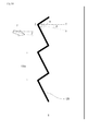
- a crosspiece 125 is formed so that a bending position Z is directed toward the flow direction F.
- the flow direction F is slanted relatively to the vertical direction of the reference line S for angle ⁇ .
- a bisector V (a long dashed double-short dashed line in the drawing) of a unit shape 125a at the bending position Z is defined.
- the bending position Z is formed so that the angle between the bisector V and the perpendicular T (see Fig. 8 ) is ⁇ .
- the angle between two tangents at suitable symmetrical positions of the unit shape 110a of the crosspiece 110 is defined as bending angle, and a bisector of the angle is defined, whereby the construction similar to the case that the crosspiece has bending shape can be realized.
- the bending position Z of the crosspiece 125 is formed to be directed along the flow direction F, whereby the fluid noise is maximally reduced similarly to the above-mentioned effect.
- action and effect similar to the crosspiece 125 can be obtained by forming a crosspiece 115 or 135 which is bent or curved relatively to the flow direction F similarly.
- a fan guard as Embodiment 6 (not shown), at least not less than 30% of the length of the crosspiece constituting the fan guard is constructed with the shape of the crosspiece 110.
- the other part is constructed with the crosspiece 100. Accordingly, even if the whole crosspiece 100 cannot be formed similarly to the crosspiece 110 because of manufacturing cost or manufacturing equipments, fixed effect can be obtained by forming a part of the crosspiece similarly to the crosspiece 110.
- the shape of the crosspiece 110 is preferably constructed only at the position corresponding to the blowoff direction.
- the fan guard may alternatively be constructed that at least not less than 30% of the length of the crosspiece constituting the fan guard is constructed with the combination of at least two of the crosspieces 110, 120 and 130.
- the straight part and circular part when viewed in plan may be constructed respectively by difference crosspieces. Accordingly, the optimum shape can be selected for each part, whereby the degree of freedom of design of the fan guard is improved.
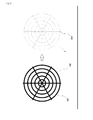
- the crosspieces 110 are constructed perpendicular lattice-like. According to this construction, the fan guard 220 has high intensity and can be manufactured cheaply.
- the crosspieces 110 are constructed lozenge lattice-like. According to this construction, the fan guard 230 has high intensity and can be manufactured cheaply.
- the crosspieces are constituted by combination of voluted portions 241 and radial portions 242.
- the pitch between windings of the voluted portions 241 is not fixed. According to this construction, the number of the crosspieces 110 per area of the fan guard 240 can be suppressed, whereby noise and pressure drop of the fan guard 240 can be reduced.
- the pitch of the voluted portions 241 the minimum, intrusion of a hand of a person or a foreign matter can be blocked certainly.
- the crosspieces 110 are constituted by combination of concentric circular portions 251 and 256 and radial portions 252 and 257.
- the number of the concentric circular portions 251 is larger than that of the radial portions 252.
- the number of the radial portions 257 is larger than that of the concentric circular portions 256.
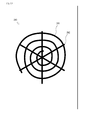
- the crosspieces 110 are constituted by combination of concentric circular portions 261 and radial portions 262. According to this construction, the number of the crosspieces 110, 115 to 135 per area of the fan guard 260 can be suppressed, whereby noise and pressure drop can be reduced. By making the pitch of the radial portions 262 the minimum, intrusion of a hand of a person or a foreign matter can be blocked certainly.
- the crosspieces 110 are constituted by combination of concentric circular portions 271 and voluted portions 272. According to this construction, the number of the crosspieces 110, 115 to 135 per area can be suppressed, whereby noise and pressure drop can be reduced. By making the pitch of the concentric circular portions 271 the minimum, intrusion of a hand of a person or a foreign matter can be blocked certainly.
- the material of the fan guards 220 to 270 of Embodiments 6 to 12 is not limited.
- the bending or curving crosspiece shape can be manufactured cheaply and easily by bending metallic lines and then connecting and fixing them by welding, or by forming synthetic resin by injection molding.
- the present invention is adoptable to a fan guard of a blower.
Landscapes
- Engineering & Computer Science (AREA)
- Mechanical Engineering (AREA)
- General Engineering & Computer Science (AREA)
- Chemical & Material Sciences (AREA)
- Combustion & Propulsion (AREA)
- Structures Of Non-Positive Displacement Pumps (AREA)
- Other Air-Conditioning Systems (AREA)
Abstract
Description
- The present invention relates to a fan guard.
- Conventionally, there is well known a blower provided in an outdoor unit of an air conditioner or the like. An inlet or an outlet of a fan of the blower is provided therein with a fan guard so as to block intrusion of a hand of a person or a foreign matter. Since the fan guard is required high air permeability and quietness, the fan guard is constructed by combining crosspieces.
- Fluid noise of the blower is divided into fan noise and guard noise. The fan noise is generated by rotation of the fan. On the other, the guard noise is air cutting noise generated by air passing through the fan guard. The volume of the guard noise is proportional to magnitude of change of pressure on the surface of the crosspiece and correlation length of a vortex generated at the crosspiece. The change of pressure is change of static pressure generated on the surface of the crosspiece at the time of passing of air flow through the fan guard. The correlation length of the vortex is length of a longitudinal vortex generated at the crosspiece.
- The Japanese Patent Laid Open Gazette
2005-351546 2006-300375 - However, the fan guards disclosed by the Japanese Patent Laid Open Gazette
2005-351546 2006-300375 - Recently, a blower and a product having the blower are required to be miniaturized. Simultaneously, the blower is required to reduce fluid noise. On the other hand, with regard to an outdoor unit of an air conditioner, a heat exchanger is miniaturized so as to save space. For obtaining the same heat exchange ability with such an outdoor unit, it is necessary to increase air flow, whereby generated fluid noise is increased inevitably. Therefore, the blower is required to reduce the fluid noise less than that of the present.
- The purpose of the present invention is to provide a fan guard which reduces fluid noise while holding the conventional function for blocking intrusion of a hand of a person or a foreign matter.
- A fan guard of the present invention is constructed so that the crosspieces are formed by continuing unit shapes bending or curving relative to a reference line along which the crosspieces of the fan guard are arranged.
- With regard to the fan guard of the present invention, preferably, each of the continuing unit shape has a wavy pattern.
- With regard to the fan guard of the present invention, preferably, each of the continuing unit shape is triangular.
- With regard to the fan guard of the present invention, preferably, each of the continuing unit shape is quadrangular.
- With regard to the fan guard of the present invention, preferably, at least two of the crosspieces of the wavy, triangular and quadrangular continuing unit shapes are combined.
- With regard to the fan guard of the present invention, preferably, a perpendicular which is led from a bending or curving position of the unit shape to the reference line is in parallel to flow direction of the blower.
- With regard to the fan guard of the present invention, preferably, a bisector which divide bending or curving angle of the unit shape into two equal parts is in parallel to flow direction of the blower.
- According to the fan guard of the present invention, by providing the crosspiece in which the bending or curving is formed, a vortex generated in the crosspiece is suppressed and the change of pressure on the surface of the crosspiece is reduced, whereby fluid noise is reduced.
The fan guard constituted by the crosspieces formed by continuing the bent unit shapes can be manufactured easily by press work of a fan guard constituted by normal round bars or square bars, whereby manufacturing of the fan guard has no hindrance. - According to the fan guard of the present invention, the above-mentioned effect can be obtained especially in the case that flow direction of fluid is known beforehand to be slanted relatively to the fan guard, such as an outlet of a blower.
-
- [
Fig. 1 ] It is a perspective view of construction of an upper surface of an engine driven heat pump having a blower according to the present invention. - [
Fig. 2 ] It is a plan view of a reference line of a crosspiece. - [
Fig. 3 ] It is a plan view of the crosspiece of Embodiment 1. - [
Fig. 4 ] It is a plan view of the crosspiece ofEmbodiment 2. - [
Fig. 5 ] It is a plan view of the crosspiece ofEmbodiment 3. - [
Fig. 6 ] It is a plan view of the effect of Embodiment 1. - [
Fig. 7 ] It is a sectional view of difference of correlation length of vortexes. - [
Fig. 8 ] It is a plan view of the crosspiece of Embodiment 4. - [
Fig. 9 ] It is a sectional view of flow direction of the blower. - [
Fig. 10 ] It is a plan view of the crosspiece ofEmbodiment 5. - [
Fig. 11 ] It is a plan view of a fan guard of Embodiment 7. - [
Fig. 12 ] It is a plan view of the fan guard of Embodiment 8. - [
Fig. 13 ] It is a plan view of the fan guard of Embodiment 9. - [
Fig. 14 ] It is a plan view of the fan guard of Embodiment 10. - [
Fig. 15 ] It is a plan view of the fan guard of Embodiment 10. - [
Fig. 16 ] It is a plan view of the fan guard of Embodiment 11. - [
Fig. 17 ] It is a plan view of the fan guard of Embodiment 12. - Explanation will be given on an engine driven heat pump 1 which is an outdoor unit having a blower with a fan guard as an embodiment of the present invention referring
Fig. 1 . The engine driven heat pump 1 is the outdoor unit that aheat exchange chamber 2 is constructed in its upper portion. Theheat exchange chamber 2 is constructed which can be ventilated for heat exchange ofoutdoor heat exchangers 3, and is a housing constituted by fourside plates 8 and atop plate 9. Inside theheat exchange chamber 2, twooutdoor heat exchangers 3, a radiator (not shown), twofans 5 and a fan motor (not shown) are disposed. The twooutdoor heat exchangers 3 are disposed respectively at front aid rear sides of theheat exchange chamber 2. - Two
outlets 6 are formed in thetop plate 9. Afan guard 200 is disposed in each of theoutlets 6. Thefan guard 200 is constructed by combiningcrosspieces 100. Each of thecrosspieces 100 is a conventional crosspiece constituting the fan guard. Outside air is sucked by thefans 5 at the front and rear sides of the chamber, exchanged its heat by theoutdoor heat exchangers 3, and then discharged upward through theoutlets 6. The radiator (not shown) also performs the heat exchange with this airflow construction. - Explanation will be given on the
fan guard 200 which is an embodiment of the present invention referringFig. 2 . Thefan guard 200 is a protective net constituted by thecrosspieces 100. Thefan guard 200 has function for blocking intrusion of a hand of a person or a foreign matter into thefans 5. On thefan guard 200, a reference line along which thecrosspieces 100 are arranged is defined as a reference line S (hereinafter, shown by dashed lines in the drawings). Hereinafter, flow direction is defined as airflow direction.
Explanation will be given on Embodiments 1 to 5 of the crosspieces constituting thefan guard 200 referringFigs. 3 to 10 . - As shown in
Fig. 3 , each ofcrosspieces 110 are formed by continuingunit shapes 110a each of which has a wavy pattern relative to the reference line S. In the case of constructing thefan guard 200, the length of each of the unit shapes 110a is at least smaller than each of gaps between thecrosspieces 110. Bending ratio of each part of theunit shape 110a is not limited. In this embodiment, the arrangement of thecrosspieces 110 relative to the flow direction is not limited. - As shown in
Fig. 4 , each ofcrosspieces 120 are formed by continuingunit shapes 120a each of which is triangular relative to the reference line S. Each of the unit shapes 120a is constituted by two sides of a triangle including a part of the reference line S, the two sides being except for the reference line S. In the case of constructing thefan guard 200, the length of each of the unit shapes 120a is at least smaller than each of gaps between thecrosspieces 120. Bending angle of each part of theunit shape 120a is not limited. In this embodiment, the arrangement of thecrosspieces 120 relative to the flow direction is not limited. - As shown in
Fig. 5 , each ofcrosspieces 130 are formed by continuingunit shapes 130a each of which is quadrangular relative to the reference line S. Each of the unit shapes 130a is constituted by three sides of a quadrangle including a part of the reference line S, the three sides being except for the reference line S. In the case of constructing thefan guard 200, the length of each of the unit shapes 130a is at least smaller than each of gaps between thecrosspieces 130. Ratio of length of each sides of the quadrangle of theunit shape 130a is not limited. In this embodiment, the arrangement of thecrosspieces 130 relative to the flow direction is not limited. - Explanation will be given on the effect of the
crosspieces 110 referringFigs. 6 and7 . InFig. 6(a) , flow direction F (an outlined arrow in the drawing, the same shall apply hereinafter) is rightward direction on the drawing surface and is perpendicular to the reference line S. A vortex is cut by the bending of thecrosspiece 110 so as to shorten the correlation length of the vortex (vortex P in the drawing). The bending of theunit shape 110a directs the cut vortex so that the vortex is directed perpendicularly to each of the unit shapes 110a of thecrosspiece 110 and the axis of the vortex is in parallel to each of the unit shapes 110a of thecrosspiece 110. The angle of the axis of the vortex is changed corresponding to the bending so that the vortex interferes with and offsets the adjacent vortex (vortex Q in the drawing), whereby the correlation length of each of the vortexes is reduced further. Accordingly, generation of vortex is suppressed so as to reduce change of pressure on the surface of thecrosspiece 110. - In
Fig. 6(b) , the flow direction F is the direction from the foreground to the background of the drawing and is perpendicular to the reference line S. Thecrosspiece 110 is indicated by a dotted line so as to make a vortex at the downstream easy to see. A vortex is cut by the bending of thecrosspiece 110 so as to shorten the correlation length of the vortex (vortex P in the drawing). The angle of the axis of the vortex is changed corresponding to the bending so that the vortex interferes with and offsets the adjacent vortex (vortex Q in the drawing). However, the degree of the offset of the adjacent vortexes is smaller than that in the case ofFig. 6(a) , whereby the effect of offset is smaller. Accordingly, generation of vortex is suppressed so as to reduce change of pressure on the surface of thecrosspiece 110. - According to the above construction, the vortex is cut so as to shorten the correlation length of the vortex.
Accordingly, by providing thecrosspiece 110 in which thewavy unit shapes 110a are continuously formed, the correlation length of the vortex generated in thecrosspiece 110 is suppressed and the change of pressure on the surface of the crosspiece is reduced, whereby fluid noise is reduced. With regard to thecrosspiece crosspiece 110. - Explanation will be given on the comparison between generation of a vortex in the
conventional crosspiece 100 and that in thecrosspiece 110 which is Embodiment 1 referringFigs. 7(a) and 7(b) . The flow direction F is rightward direction on the drawing surface and is perpendicular to the reference line S. InFig. 7(c) , the flow direction F is the direction from the foreground to the background of the drawing and is perpendicular to the reference line S. Thecrosspiece 110 is indicated by a dotted line inFig. 7(c) so as to make a vortex at the downstream easy to see. - In
Figs. 7(a) and 7(b) , it is confirmed that correlation length L of the vortex generated at the downstream of thecrosspiece 110 is smaller than correlation length L' of the vortex generated at the downstream of theconventional crosspiece 100.
InFig. 7(c) , by providing thebent crosspiece 110, the flow direction in the downstream of thecrosspiece 110 interferes and offsets mutually at the part at which the bending is remarkable, whereby it is confirmed that the vortex is suppressed and the correlation length L of the vortex is shortened. - Accordingly, by providing the
crosspiece 110 in which the bending or curving is formed, the correlation length L of the vortex generated at the downstream of thecrosspiece 110 is shortened while the change of pressure on the surface of thecrosspiece 110 is reduced. Namely, the fluid noise is reduced. With regard to thecrosspiece crosspiece 110. The effect can also be obtained regardless of the reference line S and the flow direction. - Explanation will be given on Embodiment 4 in detail referring
Fig. 8 . Embodiment 4 is another embodiment of arrangement of thecrosspiece Fig. 8 , with regard to thecrosspiece 110, a perpendicular T (hereinafter, a long dashed short dashed line in the drawing) is led from a bending position Z of theunit shape 110a to the reference line S, and the foot of the perpendicular is defined as H. In this embodiment, thecrosspiece 110 is arranged so that the perpendicular T is in parallel to the flow direction F and the reference line S is perpendicular to the flow direction F. - Accordingly, the vortexes generated at the downstream of the
crosspiece 110 interfere with and offset each other maximally, whereby the correlation length of the vortex is shortened maximally and the change of pressure on the surface of thecrosspiece 110 is reduced maximally. Namely, the fluid noise is reduced maximally. With regard to thecrosspiece crosspiece 110 can be obtained by similar arrangement relative to the flow direction F. - Explanation will be given on the flow direction F of the
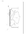
fan guard 200 of the engine driven heat pump 1 referringFig. 9 . When thefan 5 is rotated along the direction R, the flow direction F of thefan guard 200 is slanted relatively to the vertical direction of the fan 5 (a long dashed double-short dashed line inFig. 9 ). Since apropeller 7 of thefan 5 is formed so as to cut air, the flow direction F is formed substantially perpendicularly to the slant direction of thepropeller 7. The flow direction F is dispersed between products according to wind velocity or the like. Normally, the flow direction F is slanted relatively to the vertical direction of thefan 5 for 15 to 30°. - As shown in
Fig. 10 , acrosspiece 125 is formed so that a bending position Z is directed toward the flow direction F. In more detail, the flow direction F is slanted relatively to the vertical direction of the reference line S for angle β. A bisector V (a long dashed double-short dashed line in the drawing) of aunit shape 125a at the bending position Z is defined. In this embodiment, the bending position Z is formed so that the angle between the bisector V and the perpendicular T (seeFig. 8 ) is β.
When the bending shape is provided similarly to thecrosspiece 110, the angle between two tangents at suitable symmetrical positions of theunit shape 110a of thecrosspiece 110 is defined as bending angle, and a bisector of the angle is defined, whereby the construction similar to the case that the crosspiece has bending shape can be realized. - Accordingly, even if the flow direction F of the
fan 5 of the above-mentioned engine driven heat pump 1 is slanted from the vertical direction, the bending position Z of thecrosspiece 125 is formed to be directed along the flow direction F, whereby the fluid noise is maximally reduced similarly to the above-mentioned effect. With regard to thecrosspiece crosspiece 125 can be obtained by forming a crosspiece 115 or 135 which is bent or curved relatively to the flow direction F similarly. - Explanation will be given on the construction of the fan guard with the
crosspiece 110 asEmbodiments 6 to 12 referringFigs. 11 to 17 . Instead of thecrosspiece 110, thecrosspiece - With regard to a fan guard as Embodiment 6 (not shown), at least not less than 30% of the length of the crosspiece constituting the fan guard is constructed with the shape of the
crosspiece 110. The other part is constructed with thecrosspiece 100.
Accordingly, even if thewhole crosspiece 100 cannot be formed similarly to thecrosspiece 110 because of manufacturing cost or manufacturing equipments, fixed effect can be obtained by forming a part of the crosspiece similarly to thecrosspiece 110. For example, when the blowoff direction of the fan can be expected, the shape of thecrosspiece 110 is preferably constructed only at the position corresponding to the blowoff direction.
In this embodiment, it may alternatively be constructed that at least not less than 30% of the length of the crosspiece constituting the fan guard is constructed with the combination of at least two of thecrosspieces - As shown in
Fig. 11 , with regard to afan guard 220, thecrosspieces 110 are constructed perpendicular lattice-like.
According to this construction, thefan guard 220 has high intensity and can be manufactured cheaply. - As shown in
Fig. 12 , with regard to afan guard 230, thecrosspieces 110 are constructed lozenge lattice-like.
According to this construction, thefan guard 230 has high intensity and can be manufactured cheaply. - As shown in
Fig. 13 , with regard to afan guard 240, the crosspieces are constituted by combination ofvoluted portions 241 andradial portions 242. The pitch between windings of thevoluted portions 241 is not fixed.
According to this construction, the number of thecrosspieces 110 per area of thefan guard 240 can be suppressed, whereby noise and pressure drop of thefan guard 240 can be reduced. By making the pitch of thevoluted portions 241 the minimum, intrusion of a hand of a person or a foreign matter can be blocked certainly. - As shown in
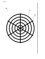
Figs. 14 and15 , with regard tofan guards crosspieces 110 are constituted by combination of concentriccircular portions radial portions Fig. 14 , with regard to thefan guard 250, the number of the concentriccircular portions 251 is larger than that of theradial portions 252. On thee other hand, as shown inFig. 15 , with regard to thefan guard 255, the number of theradial portions 257 is larger than that of the concentriccircular portions 256.
According to this construction, the number of thecrosspieces 110 per area of each of thefan guards circular portions - As shown in
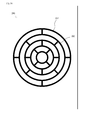
Fig. 16 , with regard to afan guard 260, thecrosspieces 110 are constituted by combination of concentriccircular portions 261 andradial portions 262.
According to this construction, the number of thecrosspieces 110, 115 to 135 per area of thefan guard 260 can be suppressed, whereby noise and pressure drop can be reduced. By making the pitch of theradial portions 262 the minimum, intrusion of a hand of a person or a foreign matter can be blocked certainly. - As shown in
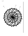
Fig. 17 , with regard to afan guard 270, thecrosspieces 110 are constituted by combination of concentriccircular portions 271 andvoluted portions 272.
According to this construction, the number of thecrosspieces 110, 115 to 135 per area can be suppressed, whereby noise and pressure drop can be reduced. By making the pitch of the concentriccircular portions 271 the minimum, intrusion of a hand of a person or a foreign matter can be blocked certainly. - In this embodiment, the material of the
fan guards 220 to 270 ofEmbodiments 6 to 12 is not limited. With regard to thefan guards 220 to 270, the bending or curving crosspiece shape can be manufactured cheaply and easily by bending metallic lines and then connecting and fixing them by welding, or by forming synthetic resin by injection molding. - The present invention is adoptable to a fan guard of a blower.
Claims (7)
- A fan guard arranged at an outlet or inlet of a blower having a fan and constituted by a plurality of crosspieces, characterized in that:the crosspieces are formed by continuing unit shapes bending or curving relative to a reference line along which the crosspieces of the fan guard are arranged.
- The fan guard as set forth in claim 1, wherein each of the continuing unit shape has a wavy pattern.
- The fan guard as set forth in claim 1, wherein each of the continuing unit shape is triangular.
- The fan guard as set forth in claim 1, wherein each of the continuing unit shape is quadrangular.
- The fan guard as set forth in claim 1, wherein at least two of the crosspieces of the wavy, triangular and quadrangular continuing unit shapes are combined.
- The fan guard as set forth in one of claims 1 to 5, wherein a perpendicular which is led from a bending or curving position of the unit shape to the reference line is in parallel to flow direction of the blower.
- The fan guard as set forth in one of claims 1 to 5, wherein a bisector which divide bending or curving angle of the unit shape into two equal parts is in parallel to flow direction of the blower.
Applications Claiming Priority (2)
| Application Number | Priority Date | Filing Date | Title |
|---|---|---|---|
| JP2007259530A JP2009085562A (en) | 2007-10-03 | 2007-10-03 | Fan guard |
| PCT/JP2008/066662 WO2009044627A1 (en) | 2007-10-03 | 2008-09-16 | Fan guard |
Publications (2)
| Publication Number | Publication Date |
|---|---|
| EP2196739A1 true EP2196739A1 (en) | 2010-06-16 |
| EP2196739A4 EP2196739A4 (en) | 2015-07-22 |
Family
ID=40526055
Family Applications (1)
| Application Number | Title | Priority Date | Filing Date |
|---|---|---|---|
| EP08835455.0A Withdrawn EP2196739A4 (en) | 2007-10-03 | 2008-09-16 | Fan guard |
Country Status (6)
| Country | Link |
|---|---|
| EP (1) | EP2196739A4 (en) |
| JP (1) | JP2009085562A (en) |
| KR (1) | KR20100043101A (en) |
| CN (1) | CN101815907B (en) |
| AU (1) | AU2008308277B2 (en) |
| WO (1) | WO2009044627A1 (en) |
Cited By (4)
| Publication number | Priority date | Publication date | Assignee | Title |
|---|---|---|---|---|
| CN102996430A (en) * | 2012-10-19 | 2013-03-27 | 无锡市普尔换热器制造有限公司 | Radiator device of stand pump |
| WO2014056467A1 (en) * | 2012-10-11 | 2014-04-17 | Uwe Stadtmüller | Protective grid for fan comprising twisted rods having a polygonal cross-section for reducing karman vortex separation noise |
| WO2015124237A1 (en) * | 2014-02-24 | 2015-08-27 | Ebm-Papst St. Georgen Gmbh & Co. Kg | Flow rectifier and fan assembly having a flow rectifier |
| US9932990B2 (en) * | 2013-01-28 | 2018-04-03 | Ebm-Papst Mulfingen Gmbh & Co. Kg | Ventilation device, in particular for heating, cooling, and/or humidifying air in residential buildings |
Families Citing this family (8)
| Publication number | Priority date | Publication date | Assignee | Title |
|---|---|---|---|---|
| JP6021141B2 (en) * | 2012-06-08 | 2016-11-09 | アルバック機工株式会社 | Pump device |
| CN102778142A (en) * | 2012-07-20 | 2012-11-14 | 无锡博利达换热器有限公司 | Oil cooler |
| JP6730671B2 (en) * | 2016-05-31 | 2020-07-29 | 株式会社富士通ゼネラル | Air conditioner outdoor unit |
| WO2018101801A1 (en) * | 2016-12-02 | 2018-06-07 | 엘지전자 주식회사 | Cookware and exhaust device |
| KR101936199B1 (en) | 2016-12-02 | 2019-01-08 | 엘지전자 주식회사 | Cooking appliance and ventilating apparatus |
| DE102017007370A1 (en) * | 2017-08-07 | 2019-02-07 | Ebm-Papst St. Georgen Gmbh & Co. Kg | Fan |
| JP6960327B2 (en) | 2017-12-20 | 2021-11-05 | 三星電子株式会社Samsung Electronics Co., Ltd. | Outdoor unit, air conditioner, fan guard, and fan guard manufacturing method |
| CN115962161A (en) * | 2022-12-29 | 2023-04-14 | 开勒环境科技(上海)股份有限公司 | Fan rectification mesh enclosure |
Family Cites Families (6)
| Publication number | Priority date | Publication date | Assignee | Title |
|---|---|---|---|---|
| JP3637705B2 (en) * | 1996-11-26 | 2005-04-13 | 三菱電機株式会社 | Air conditioner blowout structure |
| JP4380105B2 (en) * | 1999-08-09 | 2009-12-09 | ダイキン工業株式会社 | Fan guard and air conditioner for blower unit |
| JP3931624B2 (en) * | 2001-10-29 | 2007-06-20 | 三菱電機株式会社 | Blower grill and air conditioner |
| US6866474B2 (en) * | 2003-01-27 | 2005-03-15 | Lennox Industries, Inc. | Noise reduction by vortex suppression in air flow systems |
| JP4253618B2 (en) * | 2004-06-10 | 2009-04-15 | ヤンマー株式会社 | Fan guard |
| JP4764058B2 (en) | 2005-04-18 | 2011-08-31 | ヤンマー株式会社 | Blower |
-
2007
- 2007-10-03 JP JP2007259530A patent/JP2009085562A/en active Pending
-
2008
- 2008-09-16 EP EP08835455.0A patent/EP2196739A4/en not_active Withdrawn
- 2008-09-16 CN CN200880110104.0A patent/CN101815907B/en not_active Expired - Fee Related
- 2008-09-16 KR KR1020107005781A patent/KR20100043101A/en not_active Ceased
- 2008-09-16 AU AU2008308277A patent/AU2008308277B2/en not_active Ceased
- 2008-09-16 WO PCT/JP2008/066662 patent/WO2009044627A1/en not_active Ceased
Non-Patent Citations (1)
| Title |
|---|
| See references of WO2009044627A1 * |
Cited By (4)
| Publication number | Priority date | Publication date | Assignee | Title |
|---|---|---|---|---|
| WO2014056467A1 (en) * | 2012-10-11 | 2014-04-17 | Uwe Stadtmüller | Protective grid for fan comprising twisted rods having a polygonal cross-section for reducing karman vortex separation noise |
| CN102996430A (en) * | 2012-10-19 | 2013-03-27 | 无锡市普尔换热器制造有限公司 | Radiator device of stand pump |
| US9932990B2 (en) * | 2013-01-28 | 2018-04-03 | Ebm-Papst Mulfingen Gmbh & Co. Kg | Ventilation device, in particular for heating, cooling, and/or humidifying air in residential buildings |
| WO2015124237A1 (en) * | 2014-02-24 | 2015-08-27 | Ebm-Papst St. Georgen Gmbh & Co. Kg | Flow rectifier and fan assembly having a flow rectifier |
Also Published As
| Publication number | Publication date |
|---|---|
| AU2008308277A1 (en) | 2009-04-09 |
| JP2009085562A (en) | 2009-04-23 |
| WO2009044627A1 (en) | 2009-04-09 |
| EP2196739A4 (en) | 2015-07-22 |
| AU2008308277B2 (en) | 2011-04-21 |
| CN101815907A (en) | 2010-08-25 |
| CN101815907B (en) | 2014-04-02 |
| KR20100043101A (en) | 2010-04-27 |
Similar Documents
| Publication | Publication Date | Title |
|---|---|---|
| AU2008308277B2 (en) | Fan guard | |
| JP6385752B2 (en) | Outdoor unit for blower and air conditioner | |
| JP5618951B2 (en) | Multi-blade blower and air conditioner | |
| EP1780475B1 (en) | Crossflow fan | |
| US11396879B2 (en) | Cross-flow blower and indoor unit of air-conditioning device equipped with same | |
| KR20130041639A (en) | Sirocco fan and air condtioner having the same | |
| AU2014243451A1 (en) | Gearbox with a shaft | |
| US7618236B2 (en) | Fan and fan housing with toothed-type connecting elements | |
| EP3382290B1 (en) | Air conditioner | |
| CN110939607A (en) | Fan shell, fan and operation system provided with fan | |
| KR20190073342A (en) | Outdoor unit for air conditioner | |
| AU2009245176B2 (en) | Cross-flow fan and air conditioner equipped with same | |
| KR100709819B1 (en) | Crossflow fan and indoor unit of airconditioner having the same | |
| JP5293684B2 (en) | Air conditioner indoor unit | |
| US20170074525A1 (en) | Air conditioner and indoor unit of the same | |
| JP2011185273A (en) | Cross flow fan | |
| CN213514129U (en) | Air duct assembly, fan and air conditioner comprising same | |
| JP4577131B2 (en) | Blower and outdoor unit for air conditioner equipped with this blower | |
| CN210511939U (en) | Fan casing and air conditioner | |
| JPS58117393A (en) | Blower | |
| JP3079639B2 (en) | Air conditioner | |
| CN210511938U (en) | A kind of air conditioner outdoor unit fan cover and air conditioner | |
| US20250060177A1 (en) | Stone guard | |
| JP2011226409A (en) | Multi-blade fan and air conditioner equipped with the same | |
| JPWO2024232067A5 (en) |
Legal Events
| Date | Code | Title | Description |
|---|---|---|---|
| PUAI | Public reference made under article 153(3) epc to a published international application that has entered the european phase |
Free format text: ORIGINAL CODE: 0009012 |
|
| 17P | Request for examination filed |
Effective date: 20100503 |
|
| AK | Designated contracting states |
Kind code of ref document: A1 Designated state(s): AT BE BG CH CY CZ DE DK EE ES FI FR GB GR HR HU IE IS IT LI LT LU LV MC MT NL NO PL PT RO SE SI SK TR |
|
| AX | Request for extension of the european patent |
Extension state: AL BA MK RS |
|
| DAX | Request for extension of the european patent (deleted) | ||
| RA4 | Supplementary search report drawn up and despatched (corrected) |
Effective date: 20150623 |
|
| RIC1 | Information provided on ipc code assigned before grant |
Ipc: F24F 1/56 20110101ALI20150617BHEP Ipc: F24F 5/00 20060101AFI20150617BHEP Ipc: F04D 29/70 20060101ALI20150617BHEP |
|
| STAA | Information on the status of an ep patent application or granted ep patent |
Free format text: STATUS: THE APPLICATION IS DEEMED TO BE WITHDRAWN |
|
| 18D | Application deemed to be withdrawn |
Effective date: 20160121 |