EP2196643A1 - Honeycomb structured body - Google Patents
Honeycomb structured body Download PDFInfo
- Publication number
- EP2196643A1 EP2196643A1 EP10153575A EP10153575A EP2196643A1 EP 2196643 A1 EP2196643 A1 EP 2196643A1 EP 10153575 A EP10153575 A EP 10153575A EP 10153575 A EP10153575 A EP 10153575A EP 2196643 A1 EP2196643 A1 EP 2196643A1
- Authority
- EP
- European Patent Office
- Prior art keywords
- honeycomb
- honeycomb fired
- cross
- structured body
- peripheral
- Prior art date
- Legal status (The legal status is an assumption and is not a legal conclusion. Google has not performed a legal analysis and makes no representation as to the accuracy of the status listed.)
- Granted
Links
- 239000012790 adhesive layer Substances 0.000 claims abstract description 220
- 210000004027 cell Anatomy 0.000 claims abstract description 106
- 230000002093 peripheral effect Effects 0.000 claims abstract description 87
- 210000002421 cell wall Anatomy 0.000 claims abstract description 47
- 239000000919 ceramic Substances 0.000 claims description 231
- 238000000034 method Methods 0.000 abstract description 121
- 230000001172 regenerating effect Effects 0.000 abstract description 58
- 238000009826 distribution Methods 0.000 abstract description 26
- 239000010410 layer Substances 0.000 description 65
- 238000004519 manufacturing process Methods 0.000 description 59
- 239000000853 adhesive Substances 0.000 description 57
- 230000001070 adhesive effect Effects 0.000 description 57
- 230000000052 comparative effect Effects 0.000 description 44
- 239000000463 material Substances 0.000 description 42
- VZSRBBMJRBPUNF-UHFFFAOYSA-N 2-(2,3-dihydro-1H-inden-2-ylamino)-N-[3-oxo-3-(2,4,6,7-tetrahydrotriazolo[4,5-c]pyridin-5-yl)propyl]pyrimidine-5-carboxamide Chemical compound C1C(CC2=CC=CC=C12)NC1=NC=C(C=N1)C(=O)NCCC(N1CC2=C(CC1)NN=N2)=O VZSRBBMJRBPUNF-UHFFFAOYSA-N 0.000 description 37
- 239000011148 porous material Substances 0.000 description 36
- 230000005484 gravity Effects 0.000 description 34
- HBMJWWWQQXIZIP-UHFFFAOYSA-N silicon carbide Chemical compound [Si+]#[C-] HBMJWWWQQXIZIP-UHFFFAOYSA-N 0.000 description 31
- 239000000203 mixture Substances 0.000 description 28
- 229910010271 silicon carbide Inorganic materials 0.000 description 26
- 230000000694 effects Effects 0.000 description 24
- 239000011248 coating agent Substances 0.000 description 21
- 238000000576 coating method Methods 0.000 description 21
- 239000007789 gas Substances 0.000 description 15
- HMUNWXXNJPVALC-UHFFFAOYSA-N 1-[4-[2-(2,3-dihydro-1H-inden-2-ylamino)pyrimidin-5-yl]piperazin-1-yl]-2-(2,4,6,7-tetrahydrotriazolo[4,5-c]pyridin-5-yl)ethanone Chemical compound C1C(CC2=CC=CC=C12)NC1=NC=C(C=N1)N1CCN(CC1)C(CN1CC2=C(CC1)NN=N2)=O HMUNWXXNJPVALC-UHFFFAOYSA-N 0.000 description 12
- MKYBYDHXWVHEJW-UHFFFAOYSA-N N-[1-oxo-1-(2,4,6,7-tetrahydrotriazolo[4,5-c]pyridin-5-yl)propan-2-yl]-2-[[3-(trifluoromethoxy)phenyl]methylamino]pyrimidine-5-carboxamide Chemical compound O=C(C(C)NC(=O)C=1C=NC(=NC=1)NCC1=CC(=CC=C1)OC(F)(F)F)N1CC2=C(CC1)NN=N2 MKYBYDHXWVHEJW-UHFFFAOYSA-N 0.000 description 12
- 238000001035 drying Methods 0.000 description 11
- WZFUQSJFWNHZHM-UHFFFAOYSA-N 2-[4-[2-(2,3-dihydro-1H-inden-2-ylamino)pyrimidin-5-yl]piperazin-1-yl]-1-(2,4,6,7-tetrahydrotriazolo[4,5-c]pyridin-5-yl)ethanone Chemical compound C1C(CC2=CC=CC=C12)NC1=NC=C(C=N1)N1CCN(CC1)CC(=O)N1CC2=C(CC1)NN=N2 WZFUQSJFWNHZHM-UHFFFAOYSA-N 0.000 description 10
- OHVLMTFVQDZYHP-UHFFFAOYSA-N 1-(2,4,6,7-tetrahydrotriazolo[4,5-c]pyridin-5-yl)-2-[4-[2-[[3-(trifluoromethoxy)phenyl]methylamino]pyrimidin-5-yl]piperazin-1-yl]ethanone Chemical compound N1N=NC=2CN(CCC=21)C(CN1CCN(CC1)C=1C=NC(=NC=1)NCC1=CC(=CC=C1)OC(F)(F)F)=O OHVLMTFVQDZYHP-UHFFFAOYSA-N 0.000 description 9
- 239000011230 binding agent Substances 0.000 description 9
- 230000008646 thermal stress Effects 0.000 description 9
- IHCCLXNEEPMSIO-UHFFFAOYSA-N 2-[4-[2-(2,3-dihydro-1H-inden-2-ylamino)pyrimidin-5-yl]piperidin-1-yl]-1-(2,4,6,7-tetrahydrotriazolo[4,5-c]pyridin-5-yl)ethanone Chemical compound C1C(CC2=CC=CC=C12)NC1=NC=C(C=N1)C1CCN(CC1)CC(=O)N1CC2=C(CC1)NN=N2 IHCCLXNEEPMSIO-UHFFFAOYSA-N 0.000 description 8
- 239000003054 catalyst Substances 0.000 description 8
- 239000000843 powder Substances 0.000 description 8
- 230000035882 stress Effects 0.000 description 8
- 229910003460 diamond Inorganic materials 0.000 description 7
- 239000010432 diamond Substances 0.000 description 7
- 239000002245 particle Substances 0.000 description 7
- XUIMIQQOPSSXEZ-UHFFFAOYSA-N Silicon Chemical compound [Si] XUIMIQQOPSSXEZ-UHFFFAOYSA-N 0.000 description 6
- PNEYBMLMFCGWSK-UHFFFAOYSA-N aluminium oxide Inorganic materials [O-2].[O-2].[O-2].[Al+3].[Al+3] PNEYBMLMFCGWSK-UHFFFAOYSA-N 0.000 description 6
- BASFCYQUMIYNBI-UHFFFAOYSA-N platinum Chemical compound [Pt] BASFCYQUMIYNBI-UHFFFAOYSA-N 0.000 description 6
- 229910052710 silicon Inorganic materials 0.000 description 6
- 239000010703 silicon Substances 0.000 description 6
- AFCARXCZXQIEQB-UHFFFAOYSA-N N-[3-oxo-3-(2,4,6,7-tetrahydrotriazolo[4,5-c]pyridin-5-yl)propyl]-2-[[3-(trifluoromethoxy)phenyl]methylamino]pyrimidine-5-carboxamide Chemical compound O=C(CCNC(=O)C=1C=NC(=NC=1)NCC1=CC(=CC=C1)OC(F)(F)F)N1CC2=C(CC1)NN=N2 AFCARXCZXQIEQB-UHFFFAOYSA-N 0.000 description 5
- 238000005520 cutting process Methods 0.000 description 5
- 239000000314 lubricant Substances 0.000 description 5
- -1 polyoxyethylene Polymers 0.000 description 5
- LDXJRKWFNNFDSA-UHFFFAOYSA-N 2-(2,4,6,7-tetrahydrotriazolo[4,5-c]pyridin-5-yl)-1-[4-[2-[[3-(trifluoromethoxy)phenyl]methylamino]pyrimidin-5-yl]piperazin-1-yl]ethanone Chemical compound C1CN(CC2=NNN=C21)CC(=O)N3CCN(CC3)C4=CN=C(N=C4)NCC5=CC(=CC=C5)OC(F)(F)F LDXJRKWFNNFDSA-UHFFFAOYSA-N 0.000 description 4
- PEDCQBHIVMGVHV-UHFFFAOYSA-N Glycerine Chemical compound OCC(O)CO PEDCQBHIVMGVHV-UHFFFAOYSA-N 0.000 description 4
- 238000011156 evaluation Methods 0.000 description 4
- 238000010304 firing Methods 0.000 description 4
- 239000012784 inorganic fiber Substances 0.000 description 4
- 238000000465 moulding Methods 0.000 description 4
- XLYOFNOQVPJJNP-UHFFFAOYSA-N water Substances O XLYOFNOQVPJJNP-UHFFFAOYSA-N 0.000 description 4
- YLZOPXRUQYQQID-UHFFFAOYSA-N 3-(2,4,6,7-tetrahydrotriazolo[4,5-c]pyridin-5-yl)-1-[4-[2-[[3-(trifluoromethoxy)phenyl]methylamino]pyrimidin-5-yl]piperazin-1-yl]propan-1-one Chemical compound N1N=NC=2CN(CCC=21)CCC(=O)N1CCN(CC1)C=1C=NC(=NC=1)NCC1=CC(=CC=C1)OC(F)(F)F YLZOPXRUQYQQID-UHFFFAOYSA-N 0.000 description 3
- UHOVQNZJYSORNB-UHFFFAOYSA-N Benzene Chemical compound C1=CC=CC=C1 UHOVQNZJYSORNB-UHFFFAOYSA-N 0.000 description 3
- LYCAIKOWRPUZTN-UHFFFAOYSA-N Ethylene glycol Chemical compound OCCO LYCAIKOWRPUZTN-UHFFFAOYSA-N 0.000 description 3
- OKKJLVBELUTLKV-UHFFFAOYSA-N Methanol Chemical compound OC OKKJLVBELUTLKV-UHFFFAOYSA-N 0.000 description 3
- 239000012300 argon atmosphere Substances 0.000 description 3
- 238000005238 degreasing Methods 0.000 description 3
- 238000001125 extrusion Methods 0.000 description 3
- 239000010954 inorganic particle Substances 0.000 description 3
- 229920000609 methyl cellulose Polymers 0.000 description 3
- 239000001923 methylcellulose Substances 0.000 description 3
- 235000010981 methylcellulose Nutrition 0.000 description 3
- 239000004014 plasticizer Substances 0.000 description 3
- 229910052697 platinum Inorganic materials 0.000 description 3
- 229910021426 porous silicon Inorganic materials 0.000 description 3
- 238000007789 sealing Methods 0.000 description 3
- RMAQACBXLXPBSY-UHFFFAOYSA-N silicic acid Chemical compound O[Si](O)(O)O RMAQACBXLXPBSY-UHFFFAOYSA-N 0.000 description 3
- 229910052582 BN Inorganic materials 0.000 description 2
- PZNSFCLAULLKQX-UHFFFAOYSA-N Boron nitride Chemical compound N#B PZNSFCLAULLKQX-UHFFFAOYSA-N 0.000 description 2
- 229920002134 Carboxymethyl cellulose Polymers 0.000 description 2
- NIPNSKYNPDTRPC-UHFFFAOYSA-N N-[2-oxo-2-(2,4,6,7-tetrahydrotriazolo[4,5-c]pyridin-5-yl)ethyl]-2-[[3-(trifluoromethoxy)phenyl]methylamino]pyrimidine-5-carboxamide Chemical compound O=C(CNC(=O)C=1C=NC(=NC=1)NCC1=CC(=CC=C1)OC(F)(F)F)N1CC2=C(CC1)NN=N2 NIPNSKYNPDTRPC-UHFFFAOYSA-N 0.000 description 2
- KDLHZDBZIXYQEI-UHFFFAOYSA-N Palladium Chemical compound [Pd] KDLHZDBZIXYQEI-UHFFFAOYSA-N 0.000 description 2
- 229910052581 Si3N4 Inorganic materials 0.000 description 2
- VYPSYNLAJGMNEJ-UHFFFAOYSA-N Silicium dioxide Chemical compound O=[Si]=O VYPSYNLAJGMNEJ-UHFFFAOYSA-N 0.000 description 2
- 150000005215 alkyl ethers Chemical class 0.000 description 2
- 239000001768 carboxy methyl cellulose Substances 0.000 description 2
- 235000010948 carboxy methyl cellulose Nutrition 0.000 description 2
- 239000008112 carboxymethyl-cellulose Substances 0.000 description 2
- 229940105329 carboxymethylcellulose Drugs 0.000 description 2
- 238000002485 combustion reaction Methods 0.000 description 2
- 229910052878 cordierite Inorganic materials 0.000 description 2
- 235000014113 dietary fatty acids Nutrition 0.000 description 2
- JSKIRARMQDRGJZ-UHFFFAOYSA-N dimagnesium dioxido-bis[(1-oxido-3-oxo-2,4,6,8,9-pentaoxa-1,3-disila-5,7-dialuminabicyclo[3.3.1]nonan-7-yl)oxy]silane Chemical compound [Mg++].[Mg++].[O-][Si]([O-])(O[Al]1O[Al]2O[Si](=O)O[Si]([O-])(O1)O2)O[Al]1O[Al]2O[Si](=O)O[Si]([O-])(O1)O2 JSKIRARMQDRGJZ-UHFFFAOYSA-N 0.000 description 2
- KZHJGOXRZJKJNY-UHFFFAOYSA-N dioxosilane;oxo(oxoalumanyloxy)alumane Chemical compound O=[Si]=O.O=[Si]=O.O=[Al]O[Al]=O.O=[Al]O[Al]=O.O=[Al]O[Al]=O KZHJGOXRZJKJNY-UHFFFAOYSA-N 0.000 description 2
- 239000000194 fatty acid Substances 0.000 description 2
- 229930195729 fatty acid Natural products 0.000 description 2
- 150000004665 fatty acids Chemical class 0.000 description 2
- 235000011187 glycerol Nutrition 0.000 description 2
- 238000002347 injection Methods 0.000 description 2
- 239000007924 injection Substances 0.000 description 2
- 229910052863 mullite Inorganic materials 0.000 description 2
- 150000004767 nitrides Chemical class 0.000 description 2
- 229910052574 oxide ceramic Inorganic materials 0.000 description 2
- 239000011224 oxide ceramic Substances 0.000 description 2
- HQVNEWCFYHHQES-UHFFFAOYSA-N silicon nitride Chemical compound N12[Si]34N5[Si]62N3[Si]51N64 HQVNEWCFYHHQES-UHFFFAOYSA-N 0.000 description 2
- 239000004925 Acrylic resin Substances 0.000 description 1
- 229920000178 Acrylic resin Polymers 0.000 description 1
- 229910000505 Al2TiO5 Inorganic materials 0.000 description 1
- 238000007088 Archimedes method Methods 0.000 description 1
- OKTJSMMVPCPJKN-UHFFFAOYSA-N Carbon Chemical compound [C] OKTJSMMVPCPJKN-UHFFFAOYSA-N 0.000 description 1
- 239000004375 Dextrin Substances 0.000 description 1
- 229920001353 Dextrin Polymers 0.000 description 1
- LFQSCWFLJHTTHZ-UHFFFAOYSA-N Ethanol Chemical compound CCO LFQSCWFLJHTTHZ-UHFFFAOYSA-N 0.000 description 1
- 229920000663 Hydroxyethyl cellulose Polymers 0.000 description 1
- 239000004354 Hydroxyethyl cellulose Substances 0.000 description 1
- DGAQECJNVWCQMB-PUAWFVPOSA-M Ilexoside XXIX Chemical compound C[C@@H]1CC[C@@]2(CC[C@@]3(C(=CC[C@H]4[C@]3(CC[C@@H]5[C@@]4(CC[C@@H](C5(C)C)OS(=O)(=O)[O-])C)C)[C@@H]2[C@]1(C)O)C)C(=O)O[C@H]6[C@@H]([C@H]([C@@H]([C@H](O6)CO)O)O)O.[Na+] DGAQECJNVWCQMB-PUAWFVPOSA-M 0.000 description 1
- 229920003171 Poly (ethylene oxide) Polymers 0.000 description 1
- 239000002202 Polyethylene glycol Substances 0.000 description 1
- ZLMJMSJWJFRBEC-UHFFFAOYSA-N Potassium Chemical compound [K] ZLMJMSJWJFRBEC-UHFFFAOYSA-N 0.000 description 1
- NRTOMJZYCJJWKI-UHFFFAOYSA-N Titanium nitride Chemical compound [Ti]#N NRTOMJZYCJJWKI-UHFFFAOYSA-N 0.000 description 1
- 229910026551 ZrC Inorganic materials 0.000 description 1
- OTCHGXYCWNXDOA-UHFFFAOYSA-N [C].[Zr] Chemical compound [C].[Zr] OTCHGXYCWNXDOA-UHFFFAOYSA-N 0.000 description 1
- NIXOWILDQLNWCW-UHFFFAOYSA-N acrylic acid group Chemical group C(C=C)(=O)O NIXOWILDQLNWCW-UHFFFAOYSA-N 0.000 description 1
- 229910052783 alkali metal Inorganic materials 0.000 description 1
- 150000001340 alkali metals Chemical class 0.000 description 1
- 229910052784 alkaline earth metal Inorganic materials 0.000 description 1
- 229910052788 barium Inorganic materials 0.000 description 1
- DSAJWYNOEDNPEQ-UHFFFAOYSA-N barium atom Chemical compound [Ba] DSAJWYNOEDNPEQ-UHFFFAOYSA-N 0.000 description 1
- 229910010293 ceramic material Inorganic materials 0.000 description 1
- 239000003795 chemical substances by application Substances 0.000 description 1
- 150000001875 compounds Chemical class 0.000 description 1
- 238000010276 construction Methods 0.000 description 1
- 239000000356 contaminant Substances 0.000 description 1
- PMHQVHHXPFUNSP-UHFFFAOYSA-M copper(1+);methylsulfanylmethane;bromide Chemical compound Br[Cu].CSC PMHQVHHXPFUNSP-UHFFFAOYSA-M 0.000 description 1
- 235000019425 dextrin Nutrition 0.000 description 1
- 238000002276 dielectric drying Methods 0.000 description 1
- 239000002270 dispersing agent Substances 0.000 description 1
- 238000006073 displacement reaction Methods 0.000 description 1
- 239000000835 fiber Substances 0.000 description 1
- 239000010881 fly ash Substances 0.000 description 1
- 238000004108 freeze drying Methods 0.000 description 1
- 239000011521 glass Substances 0.000 description 1
- 239000010439 graphite Substances 0.000 description 1
- 229910002804 graphite Inorganic materials 0.000 description 1
- 238000007602 hot air drying Methods 0.000 description 1
- 235000019447 hydroxyethyl cellulose Nutrition 0.000 description 1
- 238000011835 investigation Methods 0.000 description 1
- 238000005259 measurement Methods 0.000 description 1
- QSHDDOUJBYECFT-UHFFFAOYSA-N mercury Chemical compound [Hg] QSHDDOUJBYECFT-UHFFFAOYSA-N 0.000 description 1
- 229910052753 mercury Inorganic materials 0.000 description 1
- 150000001247 metal acetylides Chemical class 0.000 description 1
- NFFIWVVINABMKP-UHFFFAOYSA-N methylidynetantalum Chemical compound [Ta]#C NFFIWVVINABMKP-UHFFFAOYSA-N 0.000 description 1
- 229910000510 noble metal Inorganic materials 0.000 description 1
- 229910052575 non-oxide ceramic Inorganic materials 0.000 description 1
- 239000011225 non-oxide ceramic Substances 0.000 description 1
- 239000003960 organic solvent Substances 0.000 description 1
- 230000008520 organization Effects 0.000 description 1
- 230000003647 oxidation Effects 0.000 description 1
- 238000007254 oxidation reaction Methods 0.000 description 1
- 229910052763 palladium Inorganic materials 0.000 description 1
- 239000013618 particulate matter Substances 0.000 description 1
- 229920001223 polyethylene glycol Polymers 0.000 description 1
- 229920001451 polypropylene glycol Polymers 0.000 description 1
- 238000002459 porosimetry Methods 0.000 description 1
- 229910052700 potassium Inorganic materials 0.000 description 1
- 239000011591 potassium Substances 0.000 description 1
- AABBHSMFGKYLKE-SNAWJCMRSA-N propan-2-yl (e)-but-2-enoate Chemical compound C\C=C\C(=O)OC(C)C AABBHSMFGKYLKE-SNAWJCMRSA-N 0.000 description 1
- 229910052703 rhodium Inorganic materials 0.000 description 1
- 239000010948 rhodium Substances 0.000 description 1
- MHOVAHRLVXNVSD-UHFFFAOYSA-N rhodium atom Chemical compound [Rh] MHOVAHRLVXNVSD-UHFFFAOYSA-N 0.000 description 1
- 239000003566 sealing material Substances 0.000 description 1
- 150000004760 silicates Chemical class 0.000 description 1
- 239000000377 silicon dioxide Substances 0.000 description 1
- 239000000344 soap Substances 0.000 description 1
- 229910052708 sodium Inorganic materials 0.000 description 1
- 239000011734 sodium Substances 0.000 description 1
- 239000000243 solution Substances 0.000 description 1
- 239000000126 substance Substances 0.000 description 1
- 150000005846 sugar alcohols Polymers 0.000 description 1
- 229910003468 tantalcarbide Inorganic materials 0.000 description 1
- 238000012360 testing method Methods 0.000 description 1
- 238000012546 transfer Methods 0.000 description 1
- MTPVUVINMAGMJL-UHFFFAOYSA-N trimethyl(1,1,2,2,2-pentafluoroethyl)silane Chemical compound C[Si](C)(C)C(F)(F)C(F)(F)F MTPVUVINMAGMJL-UHFFFAOYSA-N 0.000 description 1
- UONOETXJSWQNOL-UHFFFAOYSA-N tungsten carbide Chemical compound [W+]#[C-] UONOETXJSWQNOL-UHFFFAOYSA-N 0.000 description 1
- 238000001291 vacuum drying Methods 0.000 description 1
Images


Classifications
-
- B—PERFORMING OPERATIONS; TRANSPORTING
- B01—PHYSICAL OR CHEMICAL PROCESSES OR APPARATUS IN GENERAL
- B01D—SEPARATION
- B01D39/00—Filtering material for liquid or gaseous fluids
-
- F—MECHANICAL ENGINEERING; LIGHTING; HEATING; WEAPONS; BLASTING
- F01—MACHINES OR ENGINES IN GENERAL; ENGINE PLANTS IN GENERAL; STEAM ENGINES
- F01N—GAS-FLOW SILENCERS OR EXHAUST APPARATUS FOR MACHINES OR ENGINES IN GENERAL; GAS-FLOW SILENCERS OR EXHAUST APPARATUS FOR INTERNAL COMBUSTION ENGINES
- F01N3/00—Exhaust or silencing apparatus having means for purifying, rendering innocuous, or otherwise treating exhaust
- F01N3/02—Exhaust or silencing apparatus having means for purifying, rendering innocuous, or otherwise treating exhaust for cooling, or for removing solid constituents of, exhaust
- F01N3/021—Exhaust or silencing apparatus having means for purifying, rendering innocuous, or otherwise treating exhaust for cooling, or for removing solid constituents of, exhaust by means of filters
- F01N3/022—Exhaust or silencing apparatus having means for purifying, rendering innocuous, or otherwise treating exhaust for cooling, or for removing solid constituents of, exhaust by means of filters characterised by specially adapted filtering structure, e.g. honeycomb, mesh or fibrous
- F01N3/0222—Exhaust or silencing apparatus having means for purifying, rendering innocuous, or otherwise treating exhaust for cooling, or for removing solid constituents of, exhaust by means of filters characterised by specially adapted filtering structure, e.g. honeycomb, mesh or fibrous the structure being monolithic, e.g. honeycombs
-
- B—PERFORMING OPERATIONS; TRANSPORTING
- B01—PHYSICAL OR CHEMICAL PROCESSES OR APPARATUS IN GENERAL
- B01D—SEPARATION
- B01D46/00—Filters or filtering processes specially modified for separating dispersed particles from gases or vapours
- B01D46/24—Particle separators, e.g. dust precipitators, using rigid hollow filter bodies
- B01D46/2403—Particle separators, e.g. dust precipitators, using rigid hollow filter bodies characterised by the physical shape or structure of the filtering element
- B01D46/2418—Honeycomb filters
- B01D46/2451—Honeycomb filters characterized by the geometrical structure, shape, pattern or configuration or parameters related to the geometry of the structure
- B01D46/2455—Honeycomb filters characterized by the geometrical structure, shape, pattern or configuration or parameters related to the geometry of the structure of the whole honeycomb or segments
-
- B—PERFORMING OPERATIONS; TRANSPORTING
- B01—PHYSICAL OR CHEMICAL PROCESSES OR APPARATUS IN GENERAL
- B01D—SEPARATION
- B01D46/00—Filters or filtering processes specially modified for separating dispersed particles from gases or vapours
- B01D46/24—Particle separators, e.g. dust precipitators, using rigid hollow filter bodies
- B01D46/2403—Particle separators, e.g. dust precipitators, using rigid hollow filter bodies characterised by the physical shape or structure of the filtering element
- B01D46/2418—Honeycomb filters
- B01D46/2451—Honeycomb filters characterized by the geometrical structure, shape, pattern or configuration or parameters related to the geometry of the structure
- B01D46/2466—Honeycomb filters characterized by the geometrical structure, shape, pattern or configuration or parameters related to the geometry of the structure of the adhesive layers, i.e. joints between segments
-
- B—PERFORMING OPERATIONS; TRANSPORTING
- B01—PHYSICAL OR CHEMICAL PROCESSES OR APPARATUS IN GENERAL
- B01D—SEPARATION
- B01D46/00—Filters or filtering processes specially modified for separating dispersed particles from gases or vapours
- B01D46/24—Particle separators, e.g. dust precipitators, using rigid hollow filter bodies
- B01D46/2403—Particle separators, e.g. dust precipitators, using rigid hollow filter bodies characterised by the physical shape or structure of the filtering element
- B01D46/2418—Honeycomb filters
- B01D46/2451—Honeycomb filters characterized by the geometrical structure, shape, pattern or configuration or parameters related to the geometry of the structure
- B01D46/2478—Structures comprising honeycomb segments
-
- B—PERFORMING OPERATIONS; TRANSPORTING
- B01—PHYSICAL OR CHEMICAL PROCESSES OR APPARATUS IN GENERAL
- B01D—SEPARATION
- B01D46/00—Filters or filtering processes specially modified for separating dispersed particles from gases or vapours
- B01D46/24—Particle separators, e.g. dust precipitators, using rigid hollow filter bodies
- B01D46/2403—Particle separators, e.g. dust precipitators, using rigid hollow filter bodies characterised by the physical shape or structure of the filtering element
- B01D46/2418—Honeycomb filters
- B01D46/2451—Honeycomb filters characterized by the geometrical structure, shape, pattern or configuration or parameters related to the geometry of the structure
- B01D46/2482—Thickness, height, width, length or diameter
-
- B—PERFORMING OPERATIONS; TRANSPORTING
- B01—PHYSICAL OR CHEMICAL PROCESSES OR APPARATUS IN GENERAL
- B01D—SEPARATION
- B01D46/00—Filters or filtering processes specially modified for separating dispersed particles from gases or vapours
- B01D46/24—Particle separators, e.g. dust precipitators, using rigid hollow filter bodies
- B01D46/2403—Particle separators, e.g. dust precipitators, using rigid hollow filter bodies characterised by the physical shape or structure of the filtering element
- B01D46/2418—Honeycomb filters
- B01D46/2451—Honeycomb filters characterized by the geometrical structure, shape, pattern or configuration or parameters related to the geometry of the structure
- B01D46/2484—Cell density, area or aspect ratio
-
- B—PERFORMING OPERATIONS; TRANSPORTING
- B01—PHYSICAL OR CHEMICAL PROCESSES OR APPARATUS IN GENERAL
- B01D—SEPARATION
- B01D46/00—Filters or filtering processes specially modified for separating dispersed particles from gases or vapours
- B01D46/24—Particle separators, e.g. dust precipitators, using rigid hollow filter bodies
- B01D46/2403—Particle separators, e.g. dust precipitators, using rigid hollow filter bodies characterised by the physical shape or structure of the filtering element
- B01D46/2418—Honeycomb filters
- B01D46/2451—Honeycomb filters characterized by the geometrical structure, shape, pattern or configuration or parameters related to the geometry of the structure
- B01D46/2486—Honeycomb filters characterized by the geometrical structure, shape, pattern or configuration or parameters related to the geometry of the structure characterised by the shapes or configurations
- B01D46/249—Quadrangular e.g. square or diamond
-
- B—PERFORMING OPERATIONS; TRANSPORTING
- B01—PHYSICAL OR CHEMICAL PROCESSES OR APPARATUS IN GENERAL
- B01D—SEPARATION
- B01D46/00—Filters or filtering processes specially modified for separating dispersed particles from gases or vapours
- B01D46/24—Particle separators, e.g. dust precipitators, using rigid hollow filter bodies
- B01D46/2403—Particle separators, e.g. dust precipitators, using rigid hollow filter bodies characterised by the physical shape or structure of the filtering element
- B01D46/2418—Honeycomb filters
- B01D46/2498—The honeycomb filter being defined by mathematical relationships
-
- B—PERFORMING OPERATIONS; TRANSPORTING
- B01—PHYSICAL OR CHEMICAL PROCESSES OR APPARATUS IN GENERAL
- B01J—CHEMICAL OR PHYSICAL PROCESSES, e.g. CATALYSIS OR COLLOID CHEMISTRY; THEIR RELEVANT APPARATUS
- B01J35/00—Catalysts, in general, characterised by their form or physical properties
- B01J35/50—Catalysts, in general, characterised by their form or physical properties characterised by their shape or configuration
- B01J35/56—Foraminous structures having flow-through passages or channels, e.g. grids or three-dimensional monoliths
-
- F—MECHANICAL ENGINEERING; LIGHTING; HEATING; WEAPONS; BLASTING
- F01—MACHINES OR ENGINES IN GENERAL; ENGINE PLANTS IN GENERAL; STEAM ENGINES
- F01N—GAS-FLOW SILENCERS OR EXHAUST APPARATUS FOR MACHINES OR ENGINES IN GENERAL; GAS-FLOW SILENCERS OR EXHAUST APPARATUS FOR INTERNAL COMBUSTION ENGINES
- F01N3/00—Exhaust or silencing apparatus having means for purifying, rendering innocuous, or otherwise treating exhaust
- F01N3/02—Exhaust or silencing apparatus having means for purifying, rendering innocuous, or otherwise treating exhaust for cooling, or for removing solid constituents of, exhaust
- F01N3/021—Exhaust or silencing apparatus having means for purifying, rendering innocuous, or otherwise treating exhaust for cooling, or for removing solid constituents of, exhaust by means of filters
- F01N3/022—Exhaust or silencing apparatus having means for purifying, rendering innocuous, or otherwise treating exhaust for cooling, or for removing solid constituents of, exhaust by means of filters characterised by specially adapted filtering structure, e.g. honeycomb, mesh or fibrous
-
- B—PERFORMING OPERATIONS; TRANSPORTING
- B01—PHYSICAL OR CHEMICAL PROCESSES OR APPARATUS IN GENERAL
- B01D—SEPARATION
- B01D2279/00—Filters adapted for separating dispersed particles from gases or vapours specially modified for specific uses
- B01D2279/30—Filters adapted for separating dispersed particles from gases or vapours specially modified for specific uses for treatment of exhaust gases from IC Engines
-
- C—CHEMISTRY; METALLURGY
- C04—CEMENTS; CONCRETE; ARTIFICIAL STONE; CERAMICS; REFRACTORIES
- C04B—LIME, MAGNESIA; SLAG; CEMENTS; COMPOSITIONS THEREOF, e.g. MORTARS, CONCRETE OR LIKE BUILDING MATERIALS; ARTIFICIAL STONE; CERAMICS; REFRACTORIES; TREATMENT OF NATURAL STONE
- C04B2237/00—Aspects relating to ceramic laminates or to joining of ceramic articles with other articles by heating
- C04B2237/02—Aspects relating to interlayers, e.g. used to join ceramic articles with other articles by heating
- C04B2237/04—Ceramic interlayers
- C04B2237/08—Non-oxidic interlayers
- C04B2237/083—Carbide interlayers, e.g. silicon carbide interlayers
-
- C—CHEMISTRY; METALLURGY
- C04—CEMENTS; CONCRETE; ARTIFICIAL STONE; CERAMICS; REFRACTORIES
- C04B—LIME, MAGNESIA; SLAG; CEMENTS; COMPOSITIONS THEREOF, e.g. MORTARS, CONCRETE OR LIKE BUILDING MATERIALS; ARTIFICIAL STONE; CERAMICS; REFRACTORIES; TREATMENT OF NATURAL STONE
- C04B2237/00—Aspects relating to ceramic laminates or to joining of ceramic articles with other articles by heating
- C04B2237/30—Composition of layers of ceramic laminates or of ceramic or metallic articles to be joined by heating, e.g. Si substrates
- C04B2237/32—Ceramic
- C04B2237/36—Non-oxidic
- C04B2237/365—Silicon carbide
-
- F—MECHANICAL ENGINEERING; LIGHTING; HEATING; WEAPONS; BLASTING
- F01—MACHINES OR ENGINES IN GENERAL; ENGINE PLANTS IN GENERAL; STEAM ENGINES
- F01N—GAS-FLOW SILENCERS OR EXHAUST APPARATUS FOR MACHINES OR ENGINES IN GENERAL; GAS-FLOW SILENCERS OR EXHAUST APPARATUS FOR INTERNAL COMBUSTION ENGINES
- F01N2260/00—Exhaust treating devices having provisions not otherwise provided for
- F01N2260/10—Exhaust treating devices having provisions not otherwise provided for for avoiding stress caused by expansions or contractions due to temperature variations
-
- F—MECHANICAL ENGINEERING; LIGHTING; HEATING; WEAPONS; BLASTING
- F01—MACHINES OR ENGINES IN GENERAL; ENGINE PLANTS IN GENERAL; STEAM ENGINES
- F01N—GAS-FLOW SILENCERS OR EXHAUST APPARATUS FOR MACHINES OR ENGINES IN GENERAL; GAS-FLOW SILENCERS OR EXHAUST APPARATUS FOR INTERNAL COMBUSTION ENGINES
- F01N2260/00—Exhaust treating devices having provisions not otherwise provided for
- F01N2260/12—Exhaust treating devices having provisions not otherwise provided for for resisting high pressure
-
- F—MECHANICAL ENGINEERING; LIGHTING; HEATING; WEAPONS; BLASTING
- F01—MACHINES OR ENGINES IN GENERAL; ENGINE PLANTS IN GENERAL; STEAM ENGINES
- F01N—GAS-FLOW SILENCERS OR EXHAUST APPARATUS FOR MACHINES OR ENGINES IN GENERAL; GAS-FLOW SILENCERS OR EXHAUST APPARATUS FOR INTERNAL COMBUSTION ENGINES
- F01N2260/00—Exhaust treating devices having provisions not otherwise provided for
- F01N2260/18—Exhaust treating devices having provisions not otherwise provided for for improving rigidity, e.g. by wings, ribs
-
- F—MECHANICAL ENGINEERING; LIGHTING; HEATING; WEAPONS; BLASTING
- F01—MACHINES OR ENGINES IN GENERAL; ENGINE PLANTS IN GENERAL; STEAM ENGINES
- F01N—GAS-FLOW SILENCERS OR EXHAUST APPARATUS FOR MACHINES OR ENGINES IN GENERAL; GAS-FLOW SILENCERS OR EXHAUST APPARATUS FOR INTERNAL COMBUSTION ENGINES
- F01N2330/00—Structure of catalyst support or particle filter
- F01N2330/14—Sintered material
-
- F—MECHANICAL ENGINEERING; LIGHTING; HEATING; WEAPONS; BLASTING
- F01—MACHINES OR ENGINES IN GENERAL; ENGINE PLANTS IN GENERAL; STEAM ENGINES
- F01N—GAS-FLOW SILENCERS OR EXHAUST APPARATUS FOR MACHINES OR ENGINES IN GENERAL; GAS-FLOW SILENCERS OR EXHAUST APPARATUS FOR INTERNAL COMBUSTION ENGINES
- F01N2330/00—Structure of catalyst support or particle filter
- F01N2330/30—Honeycomb supports characterised by their structural details
- F01N2330/48—Honeycomb supports characterised by their structural details characterised by the number of flow passages, e.g. cell density
-
- F—MECHANICAL ENGINEERING; LIGHTING; HEATING; WEAPONS; BLASTING
- F01—MACHINES OR ENGINES IN GENERAL; ENGINE PLANTS IN GENERAL; STEAM ENGINES
- F01N—GAS-FLOW SILENCERS OR EXHAUST APPARATUS FOR MACHINES OR ENGINES IN GENERAL; GAS-FLOW SILENCERS OR EXHAUST APPARATUS FOR INTERNAL COMBUSTION ENGINES
- F01N2450/00—Methods or apparatus for fitting, inserting or repairing different elements
- F01N2450/28—Methods or apparatus for fitting, inserting or repairing different elements by using adhesive material, e.g. cement
-
- Y—GENERAL TAGGING OF NEW TECHNOLOGICAL DEVELOPMENTS; GENERAL TAGGING OF CROSS-SECTIONAL TECHNOLOGIES SPANNING OVER SEVERAL SECTIONS OF THE IPC; TECHNICAL SUBJECTS COVERED BY FORMER USPC CROSS-REFERENCE ART COLLECTIONS [XRACs] AND DIGESTS
- Y02—TECHNOLOGIES OR APPLICATIONS FOR MITIGATION OR ADAPTATION AGAINST CLIMATE CHANGE
- Y02T—CLIMATE CHANGE MITIGATION TECHNOLOGIES RELATED TO TRANSPORTATION
- Y02T10/00—Road transport of goods or passengers
- Y02T10/10—Internal combustion engine [ICE] based vehicles
- Y02T10/12—Improving ICE efficiencies
-
- Y—GENERAL TAGGING OF NEW TECHNOLOGICAL DEVELOPMENTS; GENERAL TAGGING OF CROSS-SECTIONAL TECHNOLOGIES SPANNING OVER SEVERAL SECTIONS OF THE IPC; TECHNICAL SUBJECTS COVERED BY FORMER USPC CROSS-REFERENCE ART COLLECTIONS [XRACs] AND DIGESTS
- Y10—TECHNICAL SUBJECTS COVERED BY FORMER USPC
- Y10T—TECHNICAL SUBJECTS COVERED BY FORMER US CLASSIFICATION
- Y10T428/00—Stock material or miscellaneous articles
- Y10T428/24—Structurally defined web or sheet [e.g., overall dimension, etc.]
- Y10T428/24149—Honeycomb-like
Definitions
- the present invention relates to a honeycomb structured body.
- particulate matter contained in exhaust gases discharged from internal combustion engines of vehicles such as buses and trucks, and construction machines have raised serious problems as contaminants harmful to the environment and the human body.
- various honeycomb structured bodies which are made of porous ceramics, have been proposed as filters that capture particulate in exhaust gases and purify the exhaust gases.
- a honeycomb structured body of this kind for example, a honeycomb structured body has been proposed in which, after a plurality of rectangular pillar-shaped honeycomb fired bodies have been combined with one another with an adhesive layer interposed therebetween, the combined honeycomb fired body undergoes a cutting process to be formed into a predetermined shape to manufacture the honeycomb structured body (for example, see Patent Document 1). Further, a honeycomb structured body has been also proposed in which a plurality of honeycomb fired bodies, each of which is manufactured by preliminarily being extrusion-molded into a predetermined shape, are combined with one another with an adhesive layer interposed therebetween (for example, see Patent Document 2).
- honeycomb fired body having a rectangular shape in the cross section is located in the center portion of the honeycomb structured body.
- Honeycomb fired bodies having a smaller cross-sectional area than that of the honeycomb fired bodies located in the center portion are located in the peripheral portion of the honeycomb structured body.
- a honeycomb structured body having another structure has been proposed in which, on a cross section perpendicular to a longitudinal direction thereof, a honeycomb fired body having a rectangular shape in the cross section is located in the center portion of the honeycomb structured body, and a honeycomb fired body having a cross-sectional area larger than that of a honeycomb fired body located in the center portion are located in the peripheral portion of the honeycomb structured body(for example, see Patent Document 3).
- a honeycomb structured body as an exhaust-gas purifying filter
- a high-temperature exhaust gas discharged from an internal combustion engine flows into cells of the honeycomb structured body.
- temperature of the honeycomb fired body located in the center portion tends to easily increase in comparison with that of the honeycomb fired body located in the peripheral portion.
- honeycomb structured body having a plurality of honeycomb fired bodies combined with one another with an adhesive layer interposed therebetween since normally the thermal conductivity of the adhesive layer is inferior to the thermal conductivity of the honeycomb fired bodies, the thermal conduction is intervened by the adhesive layer. Consequently, a great temperature difference tends to be caused between the center portion and the peripheral portion in the aggregated honeycomb structured body.
- the honeycomb fired bodies each having a sufficiently smaller cross-sectional area than that of the honeycomb fired bodies in the center portion, are located in the peripheral portion, and since the presence of these honeycomb fired bodies having a smaller cross-sectional area located in the peripheral portion causes an increase in the ratio of occupation of the adhesive layer, the temperature difference between the center portion and the peripheral portion tends to be greater.
- the honeycomb structured body Upon using the honeycomb structured body as an exhaust-gas purifying filter, it is required to hold the honeycomb structured body in a predetermined casing with a holding sealing material. In order to prevent displacement of the honeycomb structured body in the casing or to prevent coming off of a part of the honeycomb fired bodies from the honeycomb structured body due to the exhaust gases, it is required to surely secure the honeycomb structured body in the casing.
- the honeycomb structured body preferably has high strength for preventing damages due to compressive stress applied from the outside of the honeycomb structured body.
- the adhesive layers are formed into a grid pattern.
- the honeycomb structured body has high strength to compressive stress applied from a predetermined direction (a direction parallel to the adhesive layer), but has low strength to compressive stress applied from another direction, for example a direction which makes 45° with the adhesive layer, and the honeycomb structured body tends to be damaged due to the compressive stress from the direction.
- each of the adhesive layers crosses one another at right angles.
- the honeycomb structured body tends to fail to spread stress generated in the honeycomb structured body and the honeycomb structured body tends to be damaged.
- a honeycomb structured body according to the first invention comprises: a plurality of pillar-shaped honeycomb fired bodies that are combined with one another with an adhesive layer interposed therebetween, each of the honeycomb fired bodies having a large number of cells that are placed in parallel with one another in a longitudinal direction with a cell wall interposed therebetween, wherein
- the peripheral-portion honeycomb fired body has the area 0.9 to 1.3 times larger than the area of the center-portion honeycomb fired body in the cross section. Therefore, since no honeycomb fired body having an extremely small cross-sectional area is located in the peripheral portion of the honeycomb structured body and since the adhesive layer to be used for combining such small honeycomb fired bodies with one another is not required, the honeycomb structured body tends not to have a temperature distribution between the center portion and the peripheral portion, and unburned particulates tend not to remain upon carrying out the regenerating process.
- the area of the peripheral-portion honeycomb fired body is less than 0.9 times larger than the area of the center-portion honeycomb fired body in the cross section, a temperature distribution tends to occur between the honeycomb fired body located in the center portion and that located in the peripheral portion, and unburned particulates tend to remain upon carrying out the regenerating process.
- the area of the peripheral-portion honeycomb fired body is more than 1.3 times larger than the area of the center-portion honeycomb fired body in the cross section, cracks may occur in the honeycomb fired body due to thermal stress.
- the area of the center-portion honeycomb fired body is 900 to 2500 mm 2 in the cross section.
- the reason for this structure is described as follows. In the case that the cross-sectional area of the center-portion honeycomb fired body is less than 900 mm 2 , a large amount of adhesive tends to be required for forming the honeycomb structured body, with the result that a temperature distribution tends to occur in the honeycomb structured body and cracks tend to occur in the honeycomb fired body upon carrying out a regenerating process.
- the upper limit value of the cross-sectional area of the center-portion honeycomb fired body is preferably 2500 mm 2 . That is, the cross-sectional area of the center-portion honeycomb fired body maintained within the above range is suitable for preventing the occurrence of cracks in the honeycomb fired body upon carrying out the regenerating process.
- the shape of the peripheral-portion honeycomb fired body is preferably formed into a shape surrounded by three line segments and one arc or elliptical arc in the cross section, and two angles made by the two line segments out of the three line segments are a right angle and an obtuse angle.
- the size of the peripheral-portion honeycomb fired body in the cross section tends not to be extremely small in comparison with that of the center-portion honeycomb fired body. Therefore, the honeycomb structured body tends not to have a temperature distribution between the center portion and the peripheral portion, and unburned particulates tend not to remain upon carrying out the regenerating process.
- a honeycomb structured body according to the second invention having a round pillar-shape or cylindroid shape comprises:
- the plurality of the honeycomb fired bodies are combined with one another with the adhesive layer interposed therebetween, and the plurality of the honeycomb fired bodies include the center-portion honeycomb fired body and the peripheral-portion honeycomb fired body.
- a figure which is similar to the shape of the ceramic block in the cross section and is concentric with the shape of the ceramic block in the cross section, is drawn in the cross section with an area ratio of the figure being 49% to the area of the ceramic block in the cross section, a part of the peripheral-portion honeycomb fired body is located in the figure.
- the honeycomb structured body in the cross section perpendicular to the longitudinal direction of the honeycomb structured body comprising the center-portion honeycomb fired body and the peripheral-portion honeycomb fired body, since there is no peripheral-portion honeycomb fired body which is located only outside the figure, the honeycomb structured body tends not to have a temperature distribution between the center portion and the peripheral portion, and unburned particulates tend not to remain.
- temperature of the center-portion honeycomb fired body tends to increase more easily than that of the peripheral-portion honeycomb fired body in the honeycomb structured body.
- heat tends to be transferred to the peripheral-portion honeycomb fired bodies, and thus, unburned particulates tend not to remain.
- the honeycomb structured body tends to have a temperature distribution between the center portion and the peripheral portion, and unburned particulates tends to remain as mentioned above.
- the area of the center-portion honeycomb fired body is 900 to 2500 mm 2 in the cross section.
- the reason for this structure is described as follows. In the case that the cross-sectional area of the center-portion honeycomb fired body is less than 900 mm 2 , a large amount of adhesive tends to be required for forming the honeycomb structured body, with the result that a temperature distribution tends to occur in the honeycomb structured body and cracks tend to occur in the honeycomb fired body upon carrying out a regenerating process.
- the upper limit value of the cross-sectional area of the center-portion honeycomb fired body is preferably 2500 mm 2 . That is, the cross-sectional area of the center-portion honeycomb fired body maintained within the above range is suitable for preventing the occurrence of cracks in the honeycomb fired body upon carrying out the regenerating process.
- a honeycomb structured body according to the third invention comprises: a plurality of pillar-shaped honeycomb fired bodies that are combined with one another with an adhesive layer interposed therebetween, each of the honeycomb fired bodies having a large number of cells that are placed in parallel with one another in a longitudinal direction with a cell wall interposed therebetween, wherein
- the adhesive layer formed in a direction extending from a corner point of the center portion to the peripheral side face of the honeycomb structured body is also referred to as a "first peripheral-portion adhesive layer”
- the adhesive layer formed in a direction extending from the center portion other than the corner points thereof to the peripheral side face of the honeycomb structured body is also referred to as a "second peripheral-portion adhesive layer”, hereinafter.
- the center portion in the cross section perpendicular to the longitudinal direction of the honeycomb structured body is the area occupied by: the center-portion honeycomb fired body; the adhesive layer combining the center-portion honeycomb fired bodies with one another; and the adhesive layer combining the center-portion honeycomb fired body with the peripheral-portion honeycomb fired body.
- the peripheral portion in the cross section perpendicular to the longitudinal direction of the honeycomb structured body is the area occupied by: the peripheral-portion honeycomb fired bodies; and the adhesive layer combining the peripheral-portion honeycomb fired bodies with one another.
- the honeycomb structured body according to the third invention has the center portion and the peripheral portion, and in the peripheral portion located outside the center portion, the plurality of the peripheral-portion honeycomb fired bodies forming a part of the peripheral side face of the honeycomb structured body are combined with one another with the adhesive layer interposed therebetween.
- the angle formed by the adhesive layer extending from the corner point of the center portion to the peripheral side face of the honeycomb structured body (the first peripheral-portion adhesive layer) and at least one adhesive layer formed in a direction extending from the center portion other than the corner points thereof to the peripheral side face of the honeycomb structured body (the second peripheral-portion adhesive layer) is 40 to 50°.
- first peripheral-portion adhesive layer extends from the corner point of the center portion to the peripheral side face of the honeycomb structured body, two adhesive layers existing between the center-portion honeycomb fired body and the peripheral-portion honeycomb fired body and the first peripheral-portion adhesive layer form a Y shape in the corner point of the center portion.
- the Y-shape portion of the adhesive layer in the cross section perpendicular to the longitudinal direction of the honeycomb structured body it is possible to prevent the honeycomb structured body from being damaged.
- the angle formed by the first peripheral-portion adhesive layer and the second peripheral-portion adhesive layer means the angle formed by the straight line passing through the inside of the first peripheral-portion adhesive layer and the straight line passing through the inside of the second peripheral-portion adhesive layer.
- the center portion includes a plurality of the center-portion honeycomb fired bodies combined with one another with the adhesive layer interposed therebetween, and in the cross section perpendicular to the longitudinal direction of the honeycomb structured body, at least one adhesive layer, which is disposed between the peripheral-portion honeycomb fired bodies and formed in a direction extending from the center portion other than the corner points thereof to the peripheral side face of the honeycomb structured body, forms a straight line with at least one adhesive layer disposed between the center-portion honeycomb fired bodies.
- the adhesive layer of this kind can play a role as, so as to say, a beam for improving strength of the honeycomb structured body.
- a honeycomb structured body according to the fourth invention comprises:
- the adhesive layer on which the center of gravity exists is counted as one of adhesive layers existing on the route. Also with respect to the honeycomb structured body according to the fourth invention, upon counting the number of adhesive layers which exist on the route extending from the center of gravity of the ceramic block to the periphery of the ceramic block, the route is decided so as to pass through the smallest number of the adhesive layers.
- the honeycomb structured body according to the fourth invention comprises the ceramic block in which the plurality of the honeycomb fired bodies are combined with one another with the adhesive layer interposed therebetween, and in the honeycomb structured body, the area of the honeycomb fired body is 900 to 2500 mm 2 in the cross section, and the area of the ceramic block is 10000 to 55000 mm 2 in the cross section.
- the honeycomb structured body since the cross-sectional area of the ceramic block and the number of the adhesive layers which exist on the route extending from the center of gravity of the ceramic block to the periphery of the ceramic block in the cross section perpendicular to the longitudinal direction of the honeycomb structured body satisfy the above-mentioned relationships, the honeycomb structured body can exert the following effects:
- the ceramic block preferably has a round shape in the cross section.
- the honeycomb structured body tends not to have a temperature distribution between the center portion and the peripheral portion when the cross-sectional area of the ceramic block and the number of the adhesive layers which exist on the route extending from the center of gravity of the ceramic block to the periphery of the ceramic block in the cross section of the honeycomb structured body satisfy the above-mentioned relationships.
- the peripheral portion of the honeycomb block tends to include a honeycomb fired body having a small cross-sectional area in the case that the honeycomb block has a round cross-sectional shape, the honeycomb structured body satisfying the above relationships can avoid the tendency of this kind.
- the cross section perpendicular to the longitudinal direction of the honeycomb structured body, the cross section perpendicular to the longitudinal direction of the ceramic block, the cross section perpendicular to the longitudinal direction of the honeycomb fired body, and the cross section perpendicular to the longitudinal direction of the honeycomb molded body may be simply referred to as the cross section of a honeycomb structured body, the cross section of a ceramic block, the cross section of a honeycomb fired body, and the cross section of a honeycomb molded body.
- the cross-sectional area of a honeycomb structured body, the cross-sectional area of a ceramic block, the cross-sectional area of a honeycomb fired body, and the cross-sectional area of a honeycomb molded body may be simply referred to as the cross-sectional area perpendicular to the longitudinal direction of the honeycomb structured body, the cross-sectional area perpendicular to the longitudinal direction of the ceramic block, the cross-sectional area perpendicular to the longitudinal direction of the honeycomb fired body, and the cross-sectional area perpendicular to the longitudinal direction of the honeycomb molded body.
- the center-portion honeycomb fired body refers to a honeycomb fired body that does not form the periphery of the honeycomb structured body in the cross section perpendicular to the longitudinal direction of the honeycomb structured body
- the peripheral-portion honeycomb fired body refers to a honeycomb fired body that forms the periphery of the honeycomb structured body in the cross section perpendicular to the longitudinal direction of the honeycomb structured body.
- the peripheral-portion honeycomb fired body refers to a honeycomb fired body that forms the periphery of a ceramic block.
- honeycomb fired bodies used for forming the honeycomb structured body according to each of the first to third inventions are distinguished as the center-portion honeycomb fired bodies and the peripheral-portion honeycomb fired bodies.
- the honeycomb fired bodies are not particularly required to be distinguished, each of these is simply referred to as the honeycomb fired body.
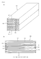
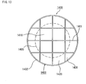
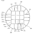
- a plurality of center-portion honeycomb fired bodies 110 having a shape shown in Figs. 2(a) and 2(b) and a plurality of peripheral-portion honeycomb fired bodies 120 having a shape shown in Fig. 3 are combined with one another, with an adhesive layer 101 interposed therebetween, to form a ceramic block 103.
- a coat layer 102 is further formed on the periphery of the ceramic block 103.
- the shape of the cross section of each of the center-portion honeycomb fired bodies 110 is a square shape.
- the shape of the cross section of each of the peripheral-portion honeycomb fired bodies 120 is formed into a shape surrounded by three line segments 120a, 120b and 120c and an arc 120d.
- the two angles made by two line segments out of these three line segments are 90° and 135°.
- the honeycomb fired bodies 110 and 120 comprise porous silicon carbide sintered bodies.
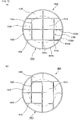
- the center-portion honeycomb fired body 110 shown in Figs. 2 (a) and 2 (b) has a structure in which a large number of cells 111 are longitudinally placed (the direction indicated by an arrow a in Fig. 2(a) ) in parallel with one another with a cell wall 113 therebetween, the cells 111 having either one of the ends sealed with a plug 112. Therefore, exhaust gas G having flown into one cell 111 with an opening on one end face (see an arrow in Fig. 2(b) ) flow out from another cell 111 with an opening on the other end face after having always passed through the cell wall 113 that separates the cells 111. Therefore, the cell wall 113 functions as a filter for capturing PM and the like.
- the peripheral-portion honeycomb fired body 120 shown in Fig. 3 has a structure in which a large number of cells 121 are longitudinally placed in parallel with one another with a cell wall 123 therebetween, and the cells 121 having either one of the ends sealed with a plug 122. Therefore, exhaust gas having flown into one cell 121 with an opening on one end face flows out from another cell 121 with an opening on the other end face after having always passed through a cell wall 123 that separates the cells 121. That is, although the outer shape of the peripheral-portion honeycomb fired body 120 is different from that of the center-portion honeycomb fired body 110, the peripheral-portion honeycomb fired body 120 has the same functions as those of the center-portion honeycomb fired body 110.
- honeycomb structured body 100 in the honeycomb structured body 100, four pieces of the center-portion honeycomb fired bodies 110 are located in the center portion of the cross section of the honeycomb structured body 100, and eight pieces of the peripheral-portion honeycomb fired bodies 120 are located on the periphery of the four pieces of the center-portion honeycomb fired bodies 110.
- honeycomb fired bodies are combined with one another with the adhesive layer 101 interposed therebetween so that the cross section of the honeycomb structured body 100 (ceramic block 103) is formed into a round shape.
- the shape of the cross section of the peripheral-portion honeycomb fired body 120 is different from that of the center-portion honeycomb fired body 110, and the cross-sectional area of the peripheral-portion honeycomb fired body 120 is 0.9 to 1.3 times larger than that of the center-portion honeycomb fired body 110. Therefore, no honeycomb fired bodies having an extremely small cross-sectional area are located in the peripheral portion of the honeycomb structured body 100, and of course, an adhesive layer to be used for combining such small honeycomb fired bodies with one another is not required. For this reason, the honeycomb structured body 100 tends not to have a temperature distribution between the center portion and the peripheral portion, and unburned particulates tend not to remain upon carrying out the regenerating process.
- the cross section of the peripheral-portion honeycomb fired body 120 is formed into the shape surrounded by the three line segments 120a, 120b and 120c and an arc 120d.
- the two angles made by two line segments out of these three line segments are 90° and 135°.
- the fact that the shape of the peripheral-portion honeycomb fired body 120 is formed into this shape is also one reason why no honeycomb fired body having an extremely small cross-sectional area is located in the peripheral portion of the honeycomb structured body 100.
- the cross-sectional area of the center-portion honeycomb fired body 110 is 900 to 2500 mm 2 .
- extrusion-molding dies corresponding to the respective shapes are used.
- the variety of cross-sectional shapes include a square cross-sectional shape and a shape surrounded by three line segments and an arc, with the two angles (made by two line segments out of these three line segments) being 90° and 135°.
- a honeycomb structured body was manufactured in the same manner as in Example 1-1, except that the sizes of a center-portion honeycomb fired body 110 and a peripheral-portion honeycomb fired body 120, each manufactured through the processes (1) to (3) of Example 1-1, were changed to the below-mentioned sizes.
- a center-portion honeycomb fired body 110 comprising a silicon carbide sintered body and having a porosity of 45%, an average pore diameter of 15 ⁇ m, a size of 36.7 mm x 36.7 mm x 150 mm, the number of cells (cell density) of 300 pcs/inch 2 and a thickness of cell walls of 0.25 mm (10 mil) was manufactured.
- the cross-sectional area of the center-portion honeycomb fired body 110 was 1347 mm 2
- the cross-sectional area of the peripheral-portion honeycomb fired body 120 was 1215 mm 2 . Therefore, the cross-sectional area of the peripheral-portion honeycomb fired body 120 was 0.90 times larger than the cross-sectional area of the center-portion honeycomb fired body 110.
- a honeycomb structured body was manufactured in the same manner as in Example 1-1, except that the sizes of a center-portion honeycomb fired body 110 and a peripheral-portion honeycomb fired body 120, each manufactured through the processes (1) to (3) of Example 1-1, were changed to the below-mentioned sizes.
- a center-portion honeycomb fired body 110 comprising a silicon carbide sintered body and having a porosity of 45%, an average pore diameter of 15 ⁇ m, a size of 32.4 mm x 32.4 mm x 150 mm, the number of cells (cell density) of 300 pcs/inch 2 and a thickness of cell walls of 0.25 mm (10 mil) was manufactured.
- the cross-sectional area of the center-portion honeycomb fired body 110 was 1050 mm 2
- the cross-sectional area of the peripheral-portion honeycomb fired body 120 was 1363 mm 2 . Therefore, the cross-sectional area of the peripheral-portion honeycomb fired body 120 was 1.30 times larger than the cross-sectional area of the center-portion honeycomb fired body 110.
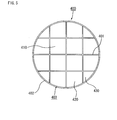
- Fig. 5 is a cross-sectional view that shows the honeycomb structured body 400 manufactured in Comparative Example 1-1
- a reference numeral 410 represents a center-portion honeycomb fired body
- reference numerals 420 and 430 represent peripheral-portion honeycomb fired bodies
- a reference numeral 401 represents an adhesive layer
- a reference numeral 402 represents a coat layer
- a reference numeral 403 represents a ceramic block.
- the cross-sectional area of the center-portion honeycomb fired body 410 is 1190.5 mm 2
- the cross-sectional area of the peripheral-portion honeycomb fired body 420 is 1095 mm 2
- the cross-sectional area of the peripheral-portion honeycomb fired body 430 is 357 mm 2 . Therefore, the cross-sectional area of the peripheral-portion honeycomb fired body 420 is 0.92 times larger than the cross-sectional area of the center-portion honeycomb fired body 410
- the cross-sectional area of the peripheral-portion honeycomb fired body 430 is 0.30 times larger than the cross-sectional area of the center-portion honeycomb fired body 410.
- a honeycomb structured body was manufactured in the same manner as in Example 1-1, except that the sizes of a center-portion honeycomb fired body 110 and a peripheral-portion honeycomb fired body 120, each manufactured through the processes (1) to (3) of Example 1-1, were changed to the below-mentioned sizes.
- a center-portion honeycomb fired body 110 comprising a silicon carbide sintered body and having a porosity of 45%, an average pore diameter of 15 ⁇ m, a size of 31.5 mm x 31.5 mm x 150 mm, the number of cells (cell density) of 300 pcs/inch 2 and a thickness of cell walls of 0.25 mm (10 mil) was manufactured.
- the cross-sectional area of the center-portion honeycomb fired body 110 was 992 mm 2
- the cross-sectional area of the peripheral-portion honeycomb fired body 120 was 1392 mm 2 . Therefore, the cross-sectional area of the peripheral-portion honeycomb fired body 120 was 1.40 times larger than the cross-sectional area of the center-portion honeycomb fired body 110.
- a regenerating process was carried out on each of the honeycomb structured bodies manufactured in Examples 1-1 to 1-3 and Comparative Examples 1-1 and 1-2 by the following method, and a regenerating rate (%) was measured by the following method based on weight differences before and after the regenerating process.
- honeycomb structured bodies according to Examples 1-1 to 1-3 and Comparative Examples 1-1 and 1-2 were placed in an exhaust passage of a 2L engine, and a commercially available catalyst supporting carrier comprising a honeycomb structured body made of cordierite (diameter: 200 mm, length: 100 mm, cell density: 400 pcs/inch 2 , amount of supported platinum: 5 g/L) was placed in the exhaust passage of the engine at a position closer to a gas-inlet side than the previously-placed honeycomb structured body as an exhaust gas purifying apparatus. Particulates were captured for 7 hours, while the engine was driven at the number of revolutions of 3000 min -1 with a torque of 50 Nm. The amount of the captured particulates was 8 g/L.
- the engine was driven at the number of revolutions of 1250 min -1 with a torque of 60 Nm, and when the temperature of the filter became constant, the state was kept for one minute. Thereafter, a post injection was performed, and then the temperature of exhaust gas was raised by utilizing the oxidation catalyst present at the front side of the exhaust gas purifying apparatus to burn particulates.
- the conditions for the post injection were set so that the temperature of the exhaust gases flowing in the honeycomb structured body became almost constant at 600°C after a lapse of one minute from the start.
- the regenerating rate of the honeycomb structured body of Example 1-1 was 85%.
- the regenerating rate of the honeycomb structured body of Example 1-2 was 80%.
- the regenerating rate of the honeycomb structured body of Example 1-3 was 88%.
- the regenerating rate of the honeycomb structured body of Comparative Example 1-1 was 70%.
- the regenerating rate of the honeycomb structured body of Comparative Example 1-2 was 90%, cracks occurred in a part of the peripheral-portion honeycomb fired body after the regenerating process.
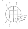
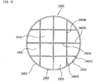
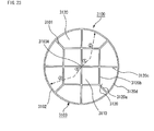
- Fig. 6 is a cross-sectional view of a honeycomb structured body according to the second embodiment of the first invention.
- the honeycomb structured body 200 of the present embodiment has a structure in which a plurality of center-portion honeycomb fired bodies 210 and pluralities of peripheral-portion honeycomb fired bodies 220 and 230 are combined with one another with an adhesive layer 201 interposed therebetween to form a ceramic block 203.
- a coat layer 202 is formed on the periphery of the ceramic block 203.
- the cross section of each of the center-portion honeycomb fired bodies 210 has a square shape.
- the cross section of each of the peripheral-portion honeycomb fired bodies 220 is formed into a shape surrounded by three line segments 220a, 220b and 220c and an arc 220d.
- the two angles made by two line segments out of these three line segments are 90°.
- the cross section of each of the peripheral-portion honeycomb fired bodies 230 is formed into a shape surrounded by three line segments 230a, 230b and 230c and an arc 230d.
- the two angles made by two line segments out of these three line segments are 90° and 135°.
- the center-portion honeycomb fired body 210 is the same as the center-portion honeycomb fired body 110 used for the honeycomb structured body of the first embodiment.
- the peripheral-portion honeycomb fired bodies 220 and 230 have the same functions as that of the center-portion honeycomb fired body 110 used for the honeycomb structured body of the first embodiment although outer shapes of those peripheral-portion honeycomb fired bodies are different from that of the center-portion honeycomb fired body 110. Moreover, the honeycomb fired bodies 210, 220 and 230 comprise porous silicon carbide sintered bodies.
- honeycomb structured body 200 As shown in Fig. 6 , in the honeycomb structured body 200, nine pieces of the center-portion honeycomb fired bodies 210 are located in the center portion of the cross section of the honeycomb structured body 200, and eight pieces of the peripheral-portion honeycomb fired bodies 220 and eight pieces of the peripheral-portion honeycomb fired bodies 230 are located on the periphery of the nine pieces of center-portion honeycomb fired bodies 210. These honeycomb fired bodies are combined with one another with the adhesive layer 201 interposed therebetween so that the cross section of the honeycomb structured body 200 (ceramic block 203) is formed into a round shape.
- each of the peripheral-portion honeycomb fired bodies 220 and 230 is different from that of the center-portion honeycomb fired body 210.
- the cross-sectional area of each of the peripheral-portion honeycomb fired bodies 220 and 230 is 0.9 to 1.3 times larger than that of the center-portion honeycomb fired body 210. Therefore, no honeycomb fired body having an extremely small cross-sectional area is located in the peripheral portion of the honeycomb structured body 200, and of course, an adhesive layer to be used for combining such small honeycomb fired bodies with one another is not required. For this reason, the honeycomb structured body 200 tends not to have a temperature distribution between the center portion and the peripheral portion, and unburned particulates tend not to remain upon carrying out the regenerating process.
- the cross section of the peripheral portion honeycomb fired body 220 is formed into the shape surrounded by the three line segments 220a, 220b and 220c and an arc 220d.
- the two angles made by two line segments out of these three line segments are 90°.
- the cross section of the peripheral portion honeycomb fired body 230 is formed into the shape surrounded by three line segments 230a, 230b and 230c and an arc 230d.
- the two angles made by two line segments out of these three line segments are 90° and 135°.
- the fact that the shape of each of the peripheral-portion honeycomb fired bodies 220 and 230 is formed into each of these shapes is also one reason why no honeycomb fired body having an extremely small cross-sectional area is located in the peripheral portion of the honeycomb structured body 200.
- the cross-sectional area of center-portion honeycomb fired body 210 is 900 to 2500 mm 2 .
- the reason for this is the same as mentioned in the first embodiment of the first invention.
- the method for manufacturing the honeycomb structured body of the present embodiment is the same as the method for manufacturing the honeycomb structured body of the first embodiment of the first invention, except for the following points. That is, the honeycomb structured body of the present embodiment can be manufactured by using the same method as the method for manufacturing the honeycomb structured body of the first embodiment of the first invention, except that the shapes of honeycomb molded bodies formed in the molding process (1) of the manufacturing method of the first embodiment of the first invention have almost the same shapes as those of the center-portion honeycomb fired body 210 and the peripheral-portion honeycomb fired bodies 220 and 230 as shown in Fig.
- the respective honeycomb fired bodies are combined with one another so that the center-portion honeycomb fired body 210 and the peripheral-portion honeycomb fired bodies 220 and 230 are located as shown in Fig. 6 .
- honeycomb structured body of the present embodiment can exert the same effects as those of the honeycomb structured body of the first embodiment of the first invention.
- Example 1-4 A regenerating process was carried out on the honeycomb structured body manufactured in Example 1-4 and a regenerating rate was measured based on weight differences, by the same method as in Example 1-1 except that a 4L engine was used instead of a 2L engine. Consequently, the regenerating rate of the honeycomb structured body of Example 1-4 was 82%.
- the honeycomb structured body is manufactured by forming the honeycomb fired body molded in the predetermined shape.
- the honeycomb structured body according to an embodiment of the first invention may be manufactured according to the method mentioned below.
- another method for manufacturing a honeycomb structured body according to an embodiment of the first invention will be described by exemplifying the case of manufacturing the honeycomb structured body according to the first embodiment.
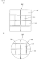
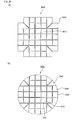
- Figs. 7(a) and 7(b) are cross-sectional views for describing one example of a method for manufacturing a honeycomb structured body according to the third embodiment of the first invention.
- the cross-sectional shape of the honeycomb structured body according to an embodiment of the first invention is not limited to a round shape.
- the cross-sectional shape may be an elliptical shape, an elongated round shape, a racetrack shape, or the like.
- Fig. 8 is a cross-sectional view of a honeycomb structured body according to another embodiment of the first invention.
- the cross-sectional shape of the honeycomb structured body illustrated in Fig. 8 is an elliptical shape.
- a honeycomb structured body 500 shown in Fig. 8 has a structure in which a plurality of center-portion honeycomb fired bodies 510 and pluralities of peripheral-portion honeycomb fired bodies 520, 530 and 540 are combined with one another with an adhesive layer 501 interposed therebetween to form a ceramic block 503. Moreover, a coat layer 502 is formed on the periphery of the ceramic block 503.
- the center-portion honeycomb fired body 510 has a square cross-sectional shape.
- the cross section of each of the peripheral-portion honeycomb fired bodies 520 is formed into a shape surrounded by three line segments 520a, 520b and 520c and an elliptical arc 520d.
- the two angles made by two line segments out of these three line segments are 90°.
- the cross section of each of the peripheral-portion honeycomb fired bodies 530 is formed into a shape surrounded by three line segments 530a, 530b and 530c and an elliptical arc 530d.
- the two angles made by two line segments out of these three line segments are 90° and 135°.
- each of the peripheral-portion honeycomb fired bodies 540 is formed into a shape surrounded by three line segments 540a, 540b and 540c and an elliptical arc 540d.
- the two angles made by two line segments out of these three line segments are 135°.
- the center-portion honeycomb fired body 510 is the same as the center-portion honeycomb fired body 110 used for the honeycomb structured body of the first embodiment.
- peripheral-portion honeycomb fired bodies 520, 530 and 540 have the same functions as that of the center-portion honeycomb fired body 110 used for the honeycomb structured body of the first embodiment although outer shapes of those peripheral-portion honeycomb fired bodies are different from that of the center-portion honeycomb fired body 110.
- the honeycomb structured body 500 includes three pieces of the center-portion honeycomb fired bodies 510 combined with one another with the adhesive layer 501 interposed therebetween, two pieces of the peripheral-portion honeycomb fired bodies 520, four pieces of the peripheral-portion honeycomb fired bodies 530 and two pieces of the peripheral-portion honeycomb fired bodies 540. These peripheral-portion honeycomb fired bodies are located on the periphery of the three pieces of the center-portion honeycomb fired bodies 510. These honeycomb fired bodies are combined with one another with the adhesive layer 501 interposed therebetween so that the cross section of the honeycomb structured body 500 (ceramic block 503) is formed into an elliptical shape.
- the cross-sectional area of each of the peripheral-portion honeycomb fired bodies 520, 530 and 540 is 0.9 to 1.3 times larger than the cross-sectional area of the center-portion honeycomb fired body 510.
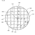
- Fig. 9 is a cross-sectional view of a honeycomb structured body according to another embodiment of the first invention.
- the cross-sectional shape of the honeycomb structured body illustrated in Fig. 9 is a racetrack shape.
- a honeycomb structured body 600 shown in Fig. 9 has a structure in which a plurality of center-portion honeycomb fired bodies 610 and pluralities of peripheral-portion honeycomb fired bodies 620, 630 and 640 are combined with one another with an adhesive layer 601 interposed therebetween to form a ceramic block 603. Moreover, a coat layer 602 is formed on the periphery of the ceramic block 603.
- the center-portion honeycomb fired body 610 has a square cross-sectional shape.
- the peripheral-portion honeycomb fired body 620 has a rectangular cross-sectional shape.
- the cross section of the peripheral-portion honeycomb fired body 630 is formed into a shape surrounded by three line segments 630a, 630b and 630c, and a curve 630d formed by one straight line and an arc.
- the two angles made by two line segments out of these three line segments are 90° and 135°.
- the cross section of the peripheral-portion honeycomb fired body 640 is formed into a shape surrounded by three line segments 640a, 640b and 640c and an arc 640d.
- the two angles made by two line segments out of these three line segments are 135°.
- the center-portion honeycomb fired body 610 is the same as the center-portion honeycomb fired body 110 used for the honeycomb structured body of the first embodiment.
- peripheral-portion honeycomb fired bodies 620, 630 and 640 have the same functions as that of the center-portion honeycomb fired body 110 used for the honeycomb structured body of the first embodiment although outer shapes of those peripheral-portion honeycomb fired bodies are different from that of the center-portion honeycomb fired body 110.
- the honeycomb structured body 600 includes three pieces of the center-portion honeycomb fired bodies 610 combined with one another with adhesive layer 601 interposed therebetween, two pieces of the peripheral-portion honeycomb fired bodies 620, four pieces of the peripheral-portion honeycomb fired bodies 630 and two pieces of the peripheral-portion honeycomb fired bodies 640. These peripheral-portion honeycomb fired bodies are located on the periphery of the three pieces of the center-portion honeycomb fired bodies 610. These honeycomb fired bodies are combined with one another with the adhesive layer 601 interposed therebetween so that the cross section of the honeycomb structured body 600 (ceramic block 603) is formed into a racetrack shape.
- the cross-sectional area of each of the peripheral-portion honeycomb fired bodies 620, 630 and 640 is 0.9 to 1.3 times larger than the cross-sectional area of the center-portion honeycomb fired body 610.
- the honeycomb structured body according to the embodiments of the first invention may have an elliptical cross-sectional shape as shown in Fig. 8 or may have a racetrack cross-sectional shape as shown in Fig. 9 .
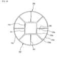
- the number of the center-portion honeycomb fired bodies is not limited to plural but may be one. More specifically, the honeycomb structured body may have a cross-sectional shape as shown in Fig. 10 .
- Fig. 10 is a cross-sectional view of a honeycomb structured body according to another embodiment of the first invention.
- the honeycomb structured body 700 as illustrated in Fig. 10 has the same structure as that of the honeycomb structured body 100 of the first embodiment, except that the number of the center-portion honeycomb fired bodies is different. That is, the honeycomb structured body 700 as illustrated in Fig. 10 comprises one center-portion honeycomb fired body 710, instead of four pieces of the honeycomb fired bodies 110 combined with one another with the adhesive layer 101 interposed therebetween in the honeycomb structured body 100 as illustrated in Fig. 1 . Compared with the center-portion honeycomb fired body 110, the center-portion honeycomb fired body 710 has a larger cross-sectional area but has the same functions.
- the cross section of the peripheral-portion honeycomb fired body 720 in the honeycomb structured body 700 is formed into a shape surrounded by three line segments 720a, 720b and 720c, and an arc 720d.
- the two angles made by two line segments out of these three line segments are 90° and 135°.
- the cross-sectional area of the peripheral-portion honeycomb fired body 720 is 0.9 to 1.3 times larger than that of the center-portion honeycomb fired body 710.
- the honeycomb structured body 700 of such an embodiment can exert the same effects as those of the honeycomb structured body of the first embodiment of the first invention.
- a reference numeral 701 represents an adhesive layer
- a reference numeral 702 represents a coat layer
- a reference numeral 703 represents a ceramic block.
- honeycomb structured body of the embodiments of the first invention having a round cross-sectional shape four or five pieces of the honeycomb fired bodies are preferably penetrated by one diameter in the cross section of the honeycomb structured body as well as another diameter that is orthogonal to the one diameter.
- the honeycomb structured bodies having such structure are suitably allowed to exert the effects of the present invention.
- one piece of honeycomb fired body located on one side adjacent to the adhesive layer is counted as one piece of honeycomb fired body penetrated by the one or another diameter.
- the honeycomb structured bodies of the embodiments of the first invention With respect to the honeycomb structured bodies of the embodiments of the first invention explained above, in the honeycomb structured body of the first embodiment, four pieces of the honeycomb fired bodies are respectively superposed on the one diameter and the another diameter (see Fig. 4 ). In the honeycomb structured body of the second embodiment, five pieces of the honeycomb fired bodies are respectively superposed on the one diameter and the another diameter (see Fig. 6 ). In the honeycomb structured body of the embodiment shown in Fig. 10 , three pieces of the honeycomb fired bodies are respectively superposed on the one diameter and the another diameter. Out of these three embodiments, the first and second embodiments are more preferable embodiments.
- Fig. 11 is a perspective view schematically showing a honeycomb structured body according to the first embodiment of the second invention.
- the honeycomb structured body 1100 shown in Fig. 11 has a structure in which a plurality of center-portion honeycomb fired bodies 1110 and a plurality of peripheral-portion honeycomb fired bodies 1120 are combined with one another with an adhesive layer 1101 interposed therebetween to form a ceramic block 1103.
- a coat layer 1102 is formed on the periphery of the ceramic block 1103.
- the center-portion honeycomb fired body 1110 has almost the same shape as that of the center-portion honeycomb fired body 110 of the honeycomb structured body 100 according to the first embodiment of the first invention, and comprises the same material as that thereof.
- the peripheral-portion honeycomb fired body 1120 has almost the same shape as that of the peripheral-portion honeycomb fired body 120 of the honeycomb structured body 100 according to the first embodiment of the first invention, and comprises the same material as that thereof.
- the center-portion honeycomb fired body 1110 and the peripheral-portion honeycomb fired body 1120 either one end of each of the cells is sealed, so that the cell wall functions as a filter for capturing PM and the like.
- honeycomb structured body 1100 in the honeycomb structured body 1100, four pieces of the center-portion honeycomb fired bodies 1110 are located in the center portion of the cross section of the honeycomb structured body 1100, and eight pieces of the peripheral-portion honeycomb fired bodies 1120 are located on the periphery of the four pieces of the center-portion honeycomb fired bodies 1110. These honeycomb fired bodies are combined with one another with the adhesive layer 1101 interposed therebetween so that the cross section of the honeycomb structured body 1100 (ceramic block 1103) is formed into a round shape.
- a part of each of the peripheral-portion honeycomb fired bodies 1120 is located in the figure 1105.
- peripheral-portion honeycomb fired bodies 1120 In the case that a part of each of the peripheral-portion honeycomb fired bodies 1120 is located in the figure 1105, there is no peripheral-portion honeycomb fired body isolated from the center of the honeycomb structured body 1100 (ceramic block 1103) by interposing the adhesive layer, so that the honeycomb structured body tends not to have a temperature distribution between the center portion and the peripheral portion.
- the cross-sectional area of the center-portion honeycomb fired body 1110 is 900 to 2500 mm 2 . This size of the cross-sectional area of the center-portion honeycomb fired body 1110 makes it possible to prevent cracks from occurring in the honeycomb structured body 1100 upon carrying out a regenerating process on the honeycomb structured body 1100.
- the honeycomb structured body according to the present embodiment can be manufactured by the same method for manufacturing the honeycomb structured body according to the first embodiment of the first invention.
- the cross-sectional shape of the honeycomb structured body 1100 manufactured in Example 2-1 is shown in Fig. 12 .
- a figure 1105 which is similar to the shape of the ceramic block 1103 in the cross section and is concentric with the shape of the ceramic block 1103 in the cross section, is drawn in the cross section with an area ratio of the figure being 49% to the area of the ceramic block 1103 in the cross section, a part of each of the peripheral-portion honeycomb fired bodies 1120 is necessarily located in the figure 1105 (see Fig. 12 ).
- a honeycomb structured body same as that in Comparative Example 1-1 was manufactured.
- Fig. 13 is a cross-sectional view that shows the honeycomb structured body 1400 manufactured in Comparative Example 2-1
- a reference numeral 1410 represents a center-portion honeycomb fired body
- reference numerals 1420 and 1430 represent peripheral-portion honeycomb fired bodies
- a reference numeral 1401 represents an adhesive layer
- a reference numeral 1402 represents a coat layer
- a reference numeral 1403 represents a ceramic block.
- the peripheral-portion honeycomb fired body 1430 is located only outside the figure 1405.
- Example 2-1 Evaluated in the same manner as in Example 1-1, the regenerating rate of the honeycomb structured body of Example 2-1 was 85%, and the regenerating rate of the honeycomb structured body of Comparative Example 2-1 was 70%. The reason of this is presumably because a large amount of unburned particulates remained upon carrying out the regenerating process in the honeycomb structured body of Comparative Example 2-1.
- Fig. 14 is a cross-sectional view of a honeycomb structured body according to the second embodiment of the second invention.
- the honeycomb structured body 1200 of the present embodiment has a structure in which a plurality of center-portion honeycomb fired bodies 1210 and pluralities of peripheral-portion honeycomb fired bodies 1220 and 1230 are combined with one another with an adhesive layer 1201 interposed therebetween to form a ceramic block 1203.
- a coat layer 1202 is formed on the periphery of the ceramic block 1203.
- the center-portion honeycomb fired body 1210 has almost the same shape as that of the center-portion honeycomb fired body 210 of the honeycomb structured body 200 according to the second embodiment of the first invention, and comprises the same material as that thereof.
- the peripheral-portion honeycomb fired bodies 1220 and 1230 have almost the same shapes as those of the peripheral-portion honeycomb fired bodies 220 and 230 of the honeycomb structured body 200 according to the second embodiment of the first invention, and comprise the same material as those thereof.
- honeycomb structured body 1200 As shown in Fig. 14 , in the honeycomb structured body 1200, nine pieces of the center-portion honeycomb fired bodies 1210 are located in the center portion of the cross section of the honeycomb structured body 1200, and eight pieces of the peripheral-portion honeycomb fired bodies 1220 and eight pieces of the peripheral-portion honeycomb fired bodies 1230 are located on the periphery of the nine pieces of center-portion honeycomb fired bodies 1210. These honeycomb fired bodies are combined with one another with the adhesive layer 1201 interposed therebetween so that the cross section of the honeycomb structured body 1200 (ceramic block 1203) is formed into a round shape.
- a part of each of the peripheral-portion honeycomb fired bodies 1220 and 1230 is located in the figure 1205.
- peripheral-portion honeycomb fired bodies 1220 and 1230 In the case that a part of each of the peripheral-portion honeycomb fired bodies 1220 and 1230 is located in the figure 1205, there is no peripheral-portion honeycomb fired body isolated from the center of the honeycomb structured body 1200 (ceramic block 1203) by interposing the adhesive layer, so that the honeycomb structured body tends not to have a temperature distribution between the center portion and the peripheral portion.
- a cross-sectional area of the center-portion honeycomb fired body 1210 is 900 to 2500 mm 2 .
- honeycomb structured body according to the present embodiment can be manufactured by the same method for manufacturing the honeycomb structured body according to the second embodiment of the first invention.
- honeycomb structured body of the present embodiment can exert the same effects as those of the honeycomb structured body of the first embodiment of the second invention.
- the cross-sectional shape of the honeycomb structured body 1200 manufactured in Example 2-2 is shown in Fig. 14 .
- a figure 1205 which is similar to the shape of the ceramic block 1203 in the cross section and is concentric with the shape of the ceramic block 1203 in the cross section, is drawn in the cross section with an area ratio of the figure being 49% to the area of the ceramic block 1203 in the cross section, a part of each of the peripheral-portion honeycomb fired bodies 1220 and 1230 is necessarily located in the figure 1205 (see Fig. 14 ).
- regenerating rate of the honeycomb structured body of Example 2-2 was 82%.
- honeycomb structured body in each of the first and second embodiments of the second invention may be manufactured in the same manner as in, for example, the third embodiment of the first invention.
- each of the peripheral-portion honeycomb fired bodies do not necessarily have the same cross-sectional shape. That is, in the embodiments of the second invention, in the case that a figure, which is similar to the shape of the ceramic block in the cross section and is concentric with the shape of the ceramic block in the cross section, is drawn in the cross section with an area ratio of the figure being 49% to the area of the ceramic block in the cross section, each of the peripheral-portion honeycomb fired bodies does not necessarily have the same cross-sectional shape as long as a part of each of the peripheral-portion honeycomb fired bodies is located in the figure. Specifically, the honeycomb structured body may have a cross-sectional shape shown in Figs. 15(a) and 15(b) . Each of Figs. 15(a) and 15(b) is a cross-sectional view of the honeycomb structured body according to another embodiment of the second invention.
- the honeycomb structured body 1500 shown in Fig. 15(a) is identical to the honeycomb structured body 1100 according to the first embodiment of the second invention except that the cross-sectional shape of the peripheral-portion honeycomb fired bodies 1520 is not the same as that of the peripheral-portion honeycomb fired bodies 1530. That is, in the honeycomb structured body 1500 shown in Fig. 15(a) , four pieces of the center-portion honeycomb fired bodies 1510 are combined with one another with the adhesive layer 1501 interposed therebetween, and four pieces of the peripheral-portion honeycomb fired bodies 1520 and four pieces of the peripheral-portion honeycomb fired bodies 1530 are located on the periphery of the four pieces of the center-portion honeycomb fired bodies 1510. These honeycomb fired bodies are combined with the adhesive layer 1501 interposed therebetween to form the ceramic block 1503.
- the coat layer 1502 is formed on the periphery of the ceramic block 1503.
- each of the peripheral-portion honeycomb fired bodies 1520 is formed into a shape surrounded by two line segments 1520a and 1520b and an arc 1520c.
- An angle made by two line segments is 90°.
- the cross section of each of the peripheral-portion honeycomb fired bodies 1530 is formed into a shape surrounded by three line segments 1530a, 1530b and 1530c and an arc 1530d.
- the two angles made by two line segments out of these three line segments are 90°.
- the honeycomb structured body 1500 provided that a figure (circle) 1505, which is similar to the shape of the ceramic block 1503 in the cross section and is concentric with the shape of the ceramic block 1503 in the cross section, is drawn in the cross section with an area ratio of the figure being 49% to the area of the ceramic block 1503 in the cross section, a part of each of the peripheral-portion honeycomb fired bodies 1520 and 1530 is located in the figure 1505.
- the honeycomb structured body 1500 according to the embodiment of this kind can also exert the same effects as those of the honeycomb structured body according to the first embodiment of the second invention.
- the peripheral-portion honeycomb fired bodies 1520 and 1530 have the same functions as that of the peripheral-portion honeycomb fired bodies 1120 of the honeycomb structured body 1100 although their cross-sectional shapes are different from that of the peripheral-portion honeycomb fired bodies 1120 of the honeycomb structured body 1100.
- the honeycomb structured body 1600 shown in Fig. 15(b) is identical to the honeycomb structured body 1500 shown in Fig. 15(a) except for the arrangement of the peripheral-portion honeycomb fired bodies 1620 and 1630. That is, in the honeycomb structured body 1600 shown in Fig. 15(b) , the peripheral-portion honeycomb fired body 1620 and the peripheral-portion honeycomb fired body 1630 are alternately placed with the adhesive layer 1601 interposed therebetween, which is different from the case in the honeycomb structured body 1500 shown in Fig. 15(a) .
- Each of the peripheral-portion honeycomb fired bodies 1620 and 1630 is identical to each of the peripheral-portion honeycomb fired bodies 1520 and 1530, respectively, except for the place in the honeycomb structured body.
- the honeycomb structured body 1600 provided that a figure (circle) 1605, which is similar to the shape of the ceramic block 1603 in the cross section and is concentric with the shape of the ceramic block 1603 in the cross section, is drawn in the cross section with an area ratio of the figure being 49% to the area of the ceramic block 1603 in the cross section, a part of each of the peripheral-portion honeycomb fired bodies 1620 and 1630 is located in the figure 1605.
- the honeycomb structured body 1600 according to the embodiment of this kind can also exert the same effects as those of the honeycomb structured body according to the first embodiment of the second invention.
- a reference numeral 1602 represents a coat layer
- a reference numeral 1610 represents a center-portion honeycomb fired body.
- Each of the honeycomb structured bodies 1500 and 1600 shown in Figs. 15(a) and 15(b) , respectively, can be manufactured in the following manner: a necessary number of two kinds of honeycomb fired bodies with each kind having a different cross-sectional shape are combined with one another with an adhesive layer interposed therebetween to manufacture an aggregated body of the honeycomb fired bodies; and the periphery thereof is cut to manufacture the honeycomb structured body. This will be described more specifically by exemplifying the case of manufacturing the honeycomb structured body 1500 referring to Figs. 16(a) and 16(b) .
- Figs. 16(a) and 16(b) are cross-sectional views for describing another example of a method for manufacturing a honeycomb structured body according to the embodiments of the second invention.
- the shape of the honeycomb structured body according to an embodiment of the second invention is not limited to a round pillar shape.
- the shape may be a cylindroid shape.
- a figure elliptical circle
- the honeycomb structured body may be a cylindroid shape having the elliptical cross-sectional shape shown in Fig. 8 .
- Fig. 17 is a perspective view schematically showing a honeycomb structured body according to the first embodiment of the third invention.
- Fig. 18 is an A-A line cross-sectional view of the honeycomb structured body shown in Fig. 17 .
- the honeycomb structured body 2100 shown in Figs. 17 and 18 has a structure in which a plurality of center-portion honeycomb fired bodies 2110 and a plurality of peripheral-portion honeycomb fired bodies 2120 are combined with one another with an adhesive layer 2101 (2101A to 2101D) interposed therebetween to form a ceramic block 2103.
- a coat layer 2102 is formed on the periphery of the ceramic block 2103.
- the center-portion honeycomb fired body 2110 has almost the same shape as that of the center-portion honeycomb fired body 110 of the honeycomb structured body 100 according to the first embodiment of the first invention, and comprises the same material as that thereof.
- the peripheral-portion honeycomb fired body 2120 has almost the same shape as that of the peripheral-portion honeycomb fired body 120 of the honeycomb structured body 100 according to the first embodiment of the first invention, and comprises the same material as that thereof.
- the center-portion honeycomb fired body 2110 and the peripheral-portion honeycomb fired body 2120 either one end of each of the cells is sealed, so that the cell wall functions as a filter for capturing PM and the like.
- honeycomb structured body 2100 in the honeycomb structured body 2100, four pieces of the center-portion honeycomb fired bodies 2110 are located in the center portion of the cross section of the honeycomb structured body 2100, and eight pieces of the peripheral-portion honeycomb fired bodies 2120 are located on the periphery of the four pieces of the center-portion honeycomb fired bodies 2110.
- These honeycomb fired bodies are combined with one another with the adhesive layers 2101 interposed therebetween so that the cross section of the honeycomb structured body 2100 (ceramic block 2103) is formed into a round shape.
- the four pieces of the center-portion honeycomb fired bodies 2110 combined with one another by interposing the adhesive layer 2101A therebetween form the center portion in the cross-section of the honeycomb structured body 2100.
- the eight pieces of the peripheral-portion honeycomb fired bodies 2120 combined with one another by interposing the adhesive layers 2101C and 2101D form the peripheral portion in the cross section of the honeycomb structured body 2100.
- the cross section of the honeycomb structured body 2100 having the above-mentioned configuration see Fig.
- the adhesive layer 2101C first peripheral-portion adhesive layer
- the adhesive layer 2101D second peripheral-portion adhesive layer
- the first peripheral-portion adhesive layer and the second peripheral-portion adhesive layer form an angle of 45° as mentioned above, it is possible to prevent damages from occurring in the honeycomb structured body.
- the first peripheral-portion adhesive layer 2101C and the adhesive layers 2101B combining the center-portion honeycomb fired body 2110 with the peripheral-portion honeycomb fired body 2120 form a Y shape.
- the adhesive layers form a Y shape in the cross-section of the honeycomb structured body as mentioned above, it is possible to prevent damages from occurring in the honeycomb structured body.
- the second peripheral-portion adhesive layer 2101D and the adhesive layers 2101A combining the center-portion honeycomb fired bodies 2110 with one another form a straight line.
- the adhesive layer of this kind can play a role as, so as to say, a beam for improving strength of the honeycomb structured body.
- the honeycomb structured body according to the present embodiment can be manufactured by the same method for manufacturing the honeycomb structured body according to the first embodiment of the first invention.
- the cross-sectional shape of the honeycomb structured body 2100 manufactured in Example 3-1 is shown in Fig. 18 .
- the first peripheral-portion adhesive layer 2101C and the second peripheral-portion adhesive layer 2101D form an angle of 45° in the cross section of the honeycomb structured body 2100.
- a honeycomb structured body same as that in Comparative Example 1-1 was manufactured.
- Fig. 19 is a cross-sectional view that shows the honeycomb structured body 2400 manufactured in Comparative Example 3-1
- a reference numeral 2410 represents a center-portion honeycomb fired body
- reference numerals 2420 and 2430 represent peripheral-portion honeycomb fired bodies
- reference numerals 2401A to 2401D represent adhesive layers
- a reference numeral 2402 represents a coat layer
- a reference numeral 2403 represents a ceramic block.
- the first peripheral-portion adhesive layer 2401C and the second peripheral-portion adhesive layer 2401D are in parallel or form an angle of 90° in the cross section. Further, in the cross section of the honeycomb structured body 2400, there is no portion where the adhesive layers form the Y shape.
- Isostatic strength of the honeycomb structured body of Example 3-1 was measured to be 9 MPa.
- isostatic strength of the honeycomb structured body of Comparative Example 3-1 was measured to be 6 MPa.
- Fig. 20 is a cross-sectional view of a honeycomb structured body according to the second embodiment of the third invention.
- the honeycomb structured body 2200 of the present embodiment has a structure in which a plurality of center-portion honeycomb fired bodies 2210 and pluralities of peripheral-portion honeycomb fired bodies 2220 and 2230 are combined with one another with adhesive layers 2201A to 2201D interposed therebetween to form a ceramic block 2203.
- a coat layer 2202 is formed on the periphery of the ceramic block 2203.
- the center-portion honeycomb fired body 2210 has almost the same shape as that of the center-portion honeycomb fired body 210 of the honeycomb structured body 200 according to the second embodiment of the first invention, and comprises the same material as that thereof.
- the peripheral-portion honeycomb fired bodies 2220 and 2230 have almost the same shape as those of the peripheral-portion honeycomb fired bodies 220 and 230 of the honeycomb structured body 200 according to the second embodiment of the first invention, and comprise the same material as those thereof.
- honeycomb structured body 2200 As shown in Fig. 20 , in the honeycomb structured body 2200, nine pieces of the center-portion honeycomb fired bodies 2210 are located in the center portion of the cross section of the honeycomb structured body 2200, and eight pieces of the peripheral-portion honeycomb fired bodies 2220 and eight pieces of the peripheral-portion honeycomb fired bodies 2230 are located on the periphery of the nine pieces of the center-portion honeycomb fired bodies 2210. These honeycomb fired bodies are combined with one another with the adhesive layers 2201A to 2201D interposed therebetween so that the cross section of the honeycomb structured body 2200 (ceramic block 2203) is formed into a round shape.
- the nine pieces of the center-portion honeycomb fired bodies 2210 combined with one another by interposing the adhesive layer 2201A therebetween form the center portion in the cross-section of the honeycomb structured body 2200.
- the total 16 pieces of the peripheral-portion honeycomb fired bodies 2220 and 2230 combined with one another by interposing the adhesive layer 2201C or 2201D form the peripheral portion in the cross section of the honeycomb structured body 2200.
- the region occupied by the nine pieces of the center-portion honeycomb fired bodies 2210, the adhesive layer 2201A combining the center-portion honeycomb fired bodies 2210 with one another, and the adhesive layer 2201B combining the center-portion honeycomb fired body 2210 with the peripheral-portion honeycomb fired bodies 2220 and 2230 corresponds to the center portion
- the region occupied by the 16 pieces of the peripheral-portion honeycomb fired bodies 2220 and 2230, and the adhesive layers 2201C and 2201D combining the peripheral-portion honeycomb fired bodies 2220 and 2230 with one another corresponds to the peripheral portion.
- the adhesive layer 2201C first peripheral-portion adhesive layer
- the adhesive layer 2201D second peripheral-portion adhesive layer
- the first peripheral-portion adhesive layer and the second peripheral-portion adhesive layer form an angle of 45° as mentioned above, it is possible to prevent damages from occurring in the honeycomb structured body.
- the first peripheral-portion adhesive layer 2201C and the adhesive layers 2201B combining the center-portion honeycomb fired body 2210 with the peripheral-portion honeycomb fired body 2220 form a Y shape.
- the adhesive layers form a Y shape in the cross-section of the honeycomb structured body as mentioned above, it is possible to prevent damages from occurring in the honeycomb structured body.
- honeycomb structured body according to the present embodiment can be manufactured by the same method for manufacturing the honeycomb structured body according to the second embodiment of the first invention.
- honeycomb structured body of the present embodiment can exert the same effects as those of the honeycomb structured body of the first embodiment of the third invention.
- the cross-sectional shape of the honeycomb structured body 2200 manufactured in Example 3-2 is shown in Fig. 20 .
- the first peripheral-portion adhesive layer 2201C and the second peripheral-portion adhesive layer 2201D form an angle of 45° in the cross section of the honeycomb structured body 2200.
- Example 3-2 Measurement of isostatic strength of the honeycomb structured body manufactured in Example 3-2 was carried out in the same manner as in Example 3-1. Isostatic strength of the honeycomb structured body manufactured in Example 3-2 was measured to be 8.5 MPa. As mentioned above, it was found that the honeycomb structured body according to the second embodiment of the third invention was suitable for preventing the honeycomb structured body from being damaged.
- honeycomb structured body according to each of the first and second embodiments of the third invention may be manufactured in the same manner as in, for example, the third embodiment of the first invention.
- the cross-sectional shape of the honeycomb structured body according to the embodiments of the third invention is not limited to a round shape.
- the cross-sectional shape may be an elliptical shape, an elongated round shape, racetrack shape or the like.
- the number of the center-portion honeycomb fired body is not limited to plural, and may be one.
- the shape of the cross section of the honeycomb structured body may be a shape shown in Fig. 21 .
- Fig. 21 is a cross-sectional view of a honeycomb structured body according to another embodiment of the third invention.
- the honeycomb structured body 2700 as illustrated in Fig. 21 has the same structure as that of the honeycomb structured body 2100 of the first embodiment of the third invention, except that the number of the center-portion honeycomb fired bodies is different. That is, the honeycomb structured body 2700 as illustrated in Fig. 21 comprises one center-portion honeycomb fired body 2710 instead of the four pieces of the center-portion honeycomb fired bodies 2110 combined with one another with the adhesive layer 2101A interposed therebetween in the honeycomb structured body 2100 as illustrated in Fig. 18 . Compared with the center-portion honeycomb fired body 2110, the center-portion honeycomb fired body 2710 has a larger cross-sectional area but has the same functions.
- the first peripheral-portion adhesive layer 2701C and the second peripheral-portion adhesive layer 2701D form an angle of 45°.
- the first peripheral-portion adhesive layer 2701C and the adhesive layers 2701B combining the center-portion honeycomb fired body 2710 with the peripheral-portion honeycomb fired body 2720 form a Y shape at a corner point of the center portion. Therefore, the honeycomb structured body 2700 can exert the same effects as the effects described in the first embodiment of the third invention.
- the reference numeral 2702 represents a coat layer
- the reference numeral 2703 represents a ceramic block.
- the angle formed by the first peripheral-portion adhesive layer and the second peripheral portion adhesive layer is not limited to 45°, and may be an angle of 40° to 50°. This is because, the angle formed by the first peripheral-portion adhesive layer and the second peripheral-portion adhesive layer within the above range is appropriate for preventing damages due to compressive stress generated in various directions on the peripheral side face of the honeycomb structured body.
- angles formed by the first peripheral-portion adhesive layer and the second peripheral-portion adhesive layer are angles of 40° to 50° in the honeycomb structured body of the embodiment mentioned above, not all of the angles should be 40° to 50° as long as at least one angle is 40° to 50° out of the angles formed by the first peripheral-portion adhesive layer and the second peripheral-portion adhesive layer in the honeycomb structured body of the present embodiment.
- the cross-sectional area of the center-portion honeycomb fired body is preferably 900 to 2500 mm 2 .
- the cross-sectional area of the center-portion honeycomb fired body is in the above range, cracks tend not to occur in the honeycomb structured body upon carrying out a regenerating process on the honeycomb structured body.
- a cross-sectional area of a ceramic block is 10000 mm 2 or more and less than 25000 mm 2 .
- Fig. 22 is a perspective view schematically showing a honeycomb structured body according to the first embodiment of the fourth invention.
- Fig. 23 is an A-A line cross-sectional view of the honeycomb structured body shown in Fig. 22 .
- the honeycomb structured body 3100 shown in Figs. 22 and 23 has a structure in which a plurality of honeycomb fired bodies 3110 and a plurality of honeycomb fired bodies 3120 are combined with one another with an adhesive layer 3101 interposed therebetween to form a ceramic block 3103.
- a coat layer 3102 is formed on the periphery of the ceramic block 3103.
- the honeycomb fired body 3110 has almost the same shape as that of the center-portion honeycomb fired body 110 of the honeycomb structured body 100 according to the first embodiment of the first invention, and comprises the same material as that thereof.
- the honeycomb fired body 3120 has almost the same shape as that of the peripheral-portion honeycomb fired body 120 of the honeycomb structured body 100 according to the first embodiment of the first invention, and comprises the same material as that thereof.
- either one end of each of the cells is sealed, so that the cell wall functions as a filter for capturing PM and the like.
- honeycomb structured body 3100 in the honeycomb structured body 3100, four pieces of the honeycomb fired bodies 3110 combined with one another with the adhesive layer 3101 interposed therebetween are located in the center portion of the cross section of the honeycomb structured body 3100, and eight pieces of the honeycomb fired bodies 3120 are located on the periphery of the four pieces of the honeycomb fired bodies 3110 so that the cross section of the honeycomb structured body 3100 (ceramic block 3103) is formed into a round shape.
- the honeycomb structured body can exert the following effects:
- the honeycomb structured body according to the present embodiment can be manufactured by the same method for manufacturing the honeycomb structured body according to the first embodiment of the first invention.
- the cross-sectional shape of the honeycomb structured body manufactured in Example 4-1 is shown in Fig. 23 .
- the cross-sectional area of the honeycomb fired body 3110 is 1190 mm 2
- the cross-sectional area of the honeycomb fired body 3120 is 1293 mm 2
- the cross-sectional area of the ceramic block 3103 is 16151 mm 2
- the number of the adhesive layers existing on a route which passes through the honeycomb fired bodies 3110 and 3120 and extends from the center of gravity 3103A of the ceramic block 3103 to the periphery of the ceramic block 3103 in the cross section is two.
- a honeycomb structured body same as that in Comparative Example 1-1 was manufactured.
- Fig. 24 is a cross-sectional view that shows the honeycomb structured body 3400 manufactured in Comparative Example 4-1, and in Fig. 24 , reference numerals 3410, 3420, and 3430 represent honeycomb fired bodies, a reference numeral 3401 represents an adhesive layer, a reference numeral 3402 represents a coat layer and a reference numeral 3403 represents a ceramic block.
- the cross-sectional area of the honeycomb fired body 3410 is 1190 mm 2
- the cross-sectional area of the honeycomb fired body 3420 is 1095 mm 2
- the cross-sectional area of the honeycomb fired body 3430 is 357 mm 2
- the cross-sectional area of the ceramic block 3403 is 16151 mm 2
- the number of the adhesive layers existing on a route which passes through the honeycomb fired bodies 3410, 3420, and 3430 and extends from the center of gravity 3403A of the ceramic block 3403 to the periphery of the ceramic block 3403 in the cross section is three
- the number of the adhesive layers existing on a route which passes through the honeycomb fired bodies 3410 and 3420 and extends from the center of gravity 3403A of the ceramic block 3403 to the periphery of the ceramic block 3403 in the cross section is two.
- Example 4-1 Evaluated in the same manner as in Example 1-1, the regenerating rate of the honeycomb structured body of Example 4-1 was 85%, and the regenerating rate of the honeycomb structured body of Comparative Example 4-1 was 70%. The reason of this is presumably because a large amount of unburned particulates remained upon carrying out the regenerating process on the honeycomb structured body of Comparative Example 4-1.
- Fig. 25 is a cross-sectional view of a honeycomb structured body according to the second embodiment of the fourth invention.
- a cross-sectional area of a ceramic block 3203 is 25000 mm 2 or more and less than 40000 mm 2 .
- the honeycomb structured body 3200 of the present embodiment has a structure in which pluralities of honeycomb fired bodies 3210, 3220 and 3230 are combined with one another with an adhesive layer 3201 interposed therebetween to form a ceramic block 3203.
- a coat layer 3202 is formed on the periphery of the ceramic block 3203.
- the honeycomb fired bodies 3210 has almost the same shape as that of the center-portion honeycomb fired bodies 210 of the honeycomb structured body 200 according to the second embodiment of the first invention, and comprises the same material as that thereof.
- the honeycomb fired bodies 3220 and 3230 have almost the same shape as those of the peripheral-portion honeycomb fired bodies 220 and 230 respectively of the honeycomb structured body 200 according to the second embodiment of the first invention, and comprise the same material as those thereof.
- a cross-sectional area of each of the honeycomb fired bodies 3210, 3220 and 3230 is 900 to 2500 mm 2 .
- the honeycomb structured body 3200 As shown in Figs. 25 , in the honeycomb structured body 3200, nine pieces of the honeycomb fired bodies 3210 combined with one another with the adhesive layer 3201 interposed therebetween are located in the center portion of the cross section of the honeycomb structured body 3200, and eight pieces of the honeycomb fired bodies 3220 and eight pieces of the honeycomb fired bodies 3230 are located on the periphery of the nine pieces of the honeycomb fired bodies 3210 so that the cross section of the honeycomb structured body 3200 (ceramic block 3203) is formed into a round shape.
- the number of the adhesive layers existing on a route which passes through the honeycomb fired bodies 3210 and 3220 and extends from the center of gravity 3203A of the ceramic block 3203 to the periphery of the ceramic block 3203 is two.
- the number of the adhesive layers existing on a route which passes through the honeycomb fired bodies 3210 and 3230 and extends from the center of gravity 3203A of the ceramic block 3203 to the periphery of the ceramic block 3203 is three.
- the honeycomb structured body can exert the following effects:
- honeycomb structured body according to the present embodiment can be manufactured by the same method for manufacturing the honeycomb structured body according to the second embodiment of the first invention.
- honeycomb structured body of the present embodiment can exert the same effects as those of the honeycomb structured body of the first embodiment of the fourth invention.
- the cross-sectional shape of the honeycomb structured body manufactured in Example 4-2 is shown in Fig. 25 .
- the cross-sectional area of the honeycomb fired body 3210 is 1190 mm 2
- the cross-sectional area of the honeycomb fired body 3220 is 1226 mm 2
- the cross-sectional area of the honeycomb fired body 3230 is 1226 mm 2
- the cross-sectional area of the ceramic block 3203 is 32302 mm 2
- the number of the adhesive layers existing on a route which passes through the honeycomb fired bodies 3210 and 3220 and extends from the center of gravity 3203A of the ceramic block 3203 to the periphery of the ceramic block 3203 in the cross section is two
- the number of the adhesive layers existing on a route which passes through the honeycomb fired bodies 3210 and 3230 and extends from the center of gravity 3203A of the ceramic block 3203 to the periphery of the ceramic block 3203 in the cross section is three.
- Fig. 26 is a cross-sectional view that shows the honeycomb structured body 4400 manufactured in Comparative Example 4-2, and in Fig. 26 , reference numerals 4410, 4420, and 4430 represent honeycomb fired bodies, a reference numeral 4401 represents an adhesive layer, a reference numeral 4402 represents a coat layer and a reference numeral 4403 represents a ceramic block.
- the cross-sectional area of the ceramic block 4403 is 32302 mm 2
- the number of the adhesive layers existing on a route which passes through the honeycomb fired bodies 4410 and 4420 and extends from the center of gravity 4403A of the ceramic block 4403 to the periphery of the ceramic block 4403 in the cross section is three
- the number of the adhesive layers existing on a route which passes through the honeycomb fired bodies 4410 and 4430 and extends from the center of gravity 4403A of the ceramic block 4403 to the periphery of the ceramic block 4403 in the cross section is four.
- Example 4-2 Evaluated in the same manner as in Example 1-4, the regenerating rate of the honeycomb structured body of Example 4-2 was 82%, and the regenerating rate of the honeycomb structured body of Comparative Example 4-2 was 65%.
- Fig. 27 is a cross-sectional view of a honeycomb structured body according to the third embodiment of the fourth invention.
- a cross-sectional area of a ceramic block 3303 is 40000 mm 2 or more and 55000 mm 2 or less.
- the honeycomb structured body 3300 of the present embodiment has a structure in which pluralities of honeycomb fired bodies 3310, 3320, 3330 and 3340 are combined with one another with an adhesive layer 3301 interposed therebetween to form a ceramic block 3303.
- a coat layer 3302 is formed on the periphery of the ceramic block 3303.
- the cross section of each of the honeycomb fired bodies 3310 and 3320 has a square shape.
- the cross section of the honeycomb fired body 3330 has a shape surrounded by four line segments 3330a, 3330b, 3330c, and 3330d and one arc 3330e, and all angles formed by two line segments of the four line segments (an angle formed by the line segments 3330a and 3330b, an angle formed by the line segments 3330b and 3330c, and an angle formed by the line segments 3330c and 3330d) are 90°.
- the cross section of the honeycomb fired body 3340 has a shape surrounded by two line segments 3340a and 3340b and one arc 3340c, and the angle formed by the two line segments (the angle formed by the line segments 3340a and 3340b) is 45°. That is, the honeycomb fired bodies 3310 and 3320 are the same as the honeycomb fired body 3110 used for the honeycomb structured body according to the first embodiment of the fourth invention.
- the honeycomb fired bodies 3330 and 3340 have the same functions as that of the honeycomb fired body 3110 of the honeycomb structured body according to the first embodiment of the fourth invention, although the outer shapes of the honeycomb fired bodies 3330 and 3340 are different from that of the honeycomb fired body 3110.
- each of the honeycomb fired bodies 3310, 3320, 3330, and 3340 is 900 to 2500 mm 2 .
- the honeycomb fired bodies 3310, 3320, 3330, and 3340 comprise a porous silicon carbide sintered body.
- honeycomb fired bodies 3310 combined with one another with the adhesive layer 3301 interposed therebetween are located near the center of the cross section of the honeycomb structured body 3300, and four pieces of the honeycomb fired bodies 3320, eight pieces of the honeycomb fired bodies 3330, and eight pieces of the honeycomb fired bodies 3340 are located on the periphery of the 21 pieces of the honeycomb fired bodies 3310.
- honeycomb fired bodies are combined with one another with the adhesive layer 3301 interposed therebetween so that the cross section of the ceramic block 3303 is formed into a round shape.
- the number of the adhesive layers existing on a route which passes through the honeycomb fired bodies 3310 and 3320 and extends from the center of gravity 3303A of the ceramic block 3303 to the periphery of the ceramic block 3303 is three.
- the number of the adhesive layers existing on a route which passes through the honeycomb fired bodies 3310 and 3330 and extends from the center of gravity 3303A of the ceramic block 3303 to the periphery of the ceramic block 3303 is four.
- the honeycomb structured body can exert the following effects:
- FIGs. 28(a) and 28(b) are cross-sectional views for describing an example of a method for manufacturing a honeycomb structured body according to the third embodiment of the fourth invention.
- honeycomb structured body of the present embodiment can exert the same effects as those of the honeycomb structured body of the first embodiment of the fourth invention.
- the cross-sectional shape of the honeycomb structured body manufactured in Example 4-3 is shown in Fig. 27 .
- the cross-sectional area of the honeycomb fired body 3310 is 1190 mm 2
- the cross-sectional area of the honeycomb fired body 3320 is 1190 mm 2
- the cross-sectional area of the honeycomb fired body 3330 is 1066 mm 2
- the cross-sectional area of the honeycomb fired body 3340 is 1093 mm 2
- the cross-sectional area of the ceramic block 3303 is 49400 mm 2
- the number of the adhesive layers existing on a route which passes through the honeycomb fired bodies 3310 and 3320 and extends from the center of gravity 3303A of the ceramic block 3303 to the periphery of the ceramic block 3303 in the cross section is three
- the number of the adhesive layers existing on a route which passes through the honeycomb fired bodies 3310 and 3330 and extends from the center of gravity 3303A of the ceramic block 3303 to the periphery of the ceramic block 3303 in the cross section
- Fig. 29 is a cross-sectional view that shows the honeycomb structured body 5400 manufactured in Comparative Example 4-3, and in Fig. 29 , reference numerals 5410, 5420, 5430, and 5440 represent honeycomb fired bodies, a reference numeral 5401 represents an adhesive layer, a reference numeral 5402 represents a coat layer and a reference numeral 5403 represents a ceramic block.
- the cross-sectional area of the honeycomb fired body 5410 is 1190 mm 2
- the cross-sectional area of the ceramic block 5403 is 50511 mm 2
- the number of the adhesive layers existing on a route which passes through the honeycomb fired bodies 5410 and 5420 and extends from the center of gravity 5403A of the ceramic block 5403 to the periphery of the ceramic block 5403 in the cross section is four
- the number of the adhesive layers existing on a route which passes through the honeycomb fired bodies 5410 and 5430 and extends from the center of gravity 5403A of the ceramic block 5403 to the periphery of the ceramic block 5403 in the cross section is five
- the number of the adhesive layers existing on a route which passes through the honeycomb fired bodies 5410 and 5440 and extends from the center of gravity 5403A of the ceramic block 5403 to the periphery of the ceramic block 5403 in the cross section is five.
- Example 4-3 Evaluated in the same manner as in Example 1-1 except that an 8L engine was used instead of the 2L engine, the regenerating rate of the honeycomb structured body of Example 4-3 was 85%. Further, the regenerating rate of the honeycomb structured body of Comparative Example 4-3 was 72%.
- honeycomb structured body according to each of the first and second embodiments of the fourth invention may be manufactured in the same manner as in, for example, the third embodiment of the first invention.
- the cross-sectional shape of the honeycomb structured body according to the embodiments of the fourth invention is not limited to a round shape.
- the cross-sectional shape may be an elliptical shape, an elongated round shape, racetrack shape, or the like.
- honeycomb structured body with either one end of each of the cells sealed was described as the honeycomb structured body according to each of the embodiments of the first to fourth inventions; however, in the honeycomb structured body according to each of the embodiments of the first to fourth inventions, each of the cells is not necessarily sealed at either one end.
- the honeycomb structured body of this kind can be used as a catalyst supporting carrier.
- each of the honeycomb fired bodies of the honeycomb structured body is not particularly limited.
- the shape is preferably a shape which makes it easy to combine the honeycomb fired bodies with one another with the adhesive layer interposed therebetween to manufacture a honeycomb structured body, and examples of the cross-sectional shape thereof include a square shape, a rectangular shape, a hexagonal shape, a sector shape, and the like.
- examples of the inorganic binder contained in the adhesive paste include silica sol, alumina sol, and the like. Each of these may be used alone, or two or more of these may be used in combination. Out of the inorganic binders, silica sol is preferably used.
- Examples of the inorganic particles contained in the adhesive paste include carbides, nitrides, and the like, and more specifically, inorganic powder made from silicon carbide, silicon nitride, boron nitride and the like. Each of these may be used alone, or two or more kinds of these may be used in combination. Out of the inorganic particles, silicon carbide is preferably used due to its superior thermal conductivity.
- Examples of at least one of the inorganic fibers and whiskers contained in the adhesive paste include at least one of inorganic fibers and whiskers made of silica-alumina, mullite, alumina, silica or the like. Each of these materials may be used alone, or two or more of these may be used in combination. Out of the inorganic fibers, alumina fibers are preferably used.
- a porosity of the honeycomb fired body of the honeycomb structured body according to each of the embodiments of the first to fourth inventions is preferably 35 to 60%.
- the porosity of less than 35% tends to cause clogging in the honeycomb structured body.
- the porosity exceeding 60% tends to cause a reduction in the strength of the honeycomb fired body, resulting in easy breakage.
- the average pore diameter of the honeycomb fired body of the honeycomb structured body according to each of the embodiments of the first to fourth inventions is preferably 5 to 30 ⁇ m.
- the average pore diameter of less than 5 ⁇ m tends to easily cause clogging of particulates.
- the average pore diameter exceeding 30 ⁇ m tends to allow particulates to easily pass through the pores.
- the honeycomb fired body may fail to capture the particulates, and thus, the honeycomb structured body may fail to function as a filter.
- the porosity and the average pore diameter can be measured by conventionally known methods such as a mercury porosimetry, Archimedes method, and a measuring method using a scanning electronic microscope (SEM).
- conventionally known methods such as a mercury porosimetry, Archimedes method, and a measuring method using a scanning electronic microscope (SEM).
- the cell density in the cross-section perpendicular to the longitudinal direction of the honeycomb fired body constituting the honeycomb structured body according to each of the embodiments of the first to fourth inventions is not particularly limited.
- a preferable lower limit thereof is 31.0 pcs/cm 2 (200 pcs/inch 2 ) and a preferable upper limit is 93.0 pcs/cm 2 (600 pcs/inch 2 ).
- a more preferable lower limit is 38.8 pcs/cm 2 (250 pcs/inch 2 ) and a more preferable upper limit is 77.5 pcs/cm 2 (500 pcs/inch 2 ).
- the thickness of the cell walls of the honeycomb fired body constituting the honeycomb structured body is not particularly limited, and preferably 0.1 to 0.4 mm.
- the main component of the honeycomb fired body constituting the honeycomb structured body according to each of the embodiments of the first to fourth inventions is not limited to silicon carbide, and may be powders of the following ceramics: nitride ceramics such as aluminum nitride, silicon nitride, boron nitride, and titanium nitride; carbide ceramics such as zirconium carbide, titanium carbide, tantalum carbide, and tungsten carbide; oxide ceramics such as cordierite, aluminum titanate; and the like.
- nitride ceramics such as aluminum nitride, silicon nitride, boron nitride, and titanium nitride
- carbide ceramics such as zirconium carbide, titanium carbide, tantalum carbide, and tungsten carbide
- oxide ceramics such as cordierite, aluminum titanate; and the like.
- non-oxide ceramics are preferable, and silicon carbide is particularly preferable. This is because they are excellent
- ceramic materials such as silicon-containing ceramics, in which the above-mentioned ceramic is blended with metallic silicon, and ceramics bonded by silicon or silicate compounds can also be used as the constitutional material.
- silicon carbide blended with metallic silicon silicon-containing silicon carbide
- ceramics of silicon-containing silicon carbide including 60% by weight or more of silicon carbide are preferable.
- the particle diameter of the ceramic powder is not particularly limited, and the silicon carbide powder that tends not to cause the case where the size of the honeycomb fired body manufactured by the following firing treatment becomes smaller than that of the honeycomb molded body after degreased is preferable.
- the organic binder to be mixed in the wet mixture is not particularly limited, and examples thereof include methyl cellulose, carboxymethyl cellulose, hydroxyethyl cellulose, polyethylene glycol, and the like. Methyl cellulose is preferable out of these.
- the binder is preferably blended at a ratio of 1 to 10 parts by weight per 100 parts by weight of the ceramic powder.
- the plasticizer to be mixed in the wet mixture is not particularly limited, and examples thereof include glycerin and the like.
- the lubricant to be mixed in the wet mixture is not particularly limited, and examples thereof include polyoxyalkylene compounds such as polyoxyethylene alkyl ether, polyoxypropylene alkyl ether, and the like. Specific examples of the lubricant include polyoxyethylene monobutyl ether, polyoxypropylene monobutyl ether, and the like. Also, in some cases, the plasticizer or lubricant may not be mixed in the wet mixture.
- a dispersant solution such as water, organic solvents such as benzene, and alcohol such as methanol.
- a forming auxiliary is not particularly limited, and examples thereof include ethylene glycol, dextrin, fatty acids, fatty acid soap, polyalcohol, and the like.
- balloons which are fine hollow spheres containing oxide ceramic as a component, and a pore-forming agent such as spherical acrylic particles or graphite to the wet mixture, if necessary.
- the balloons are not particularly limited, and examples thereof include alumina balloons, glass micro balloons, shirasu balloons, fly ash balloons (FA balloons), mullite balloons, and the like. Alumina balloons are preferable out of these.
- the plug material paste for sealing the cells is not particularly limited, and the plug, manufactured in the subsequent process, preferably has a porosity of 30 to 75%.
- the plug manufactured in the subsequent process, preferably has a porosity of 30 to 75%.
- a catalyst for converting exhaust gases may be supported on the honeycomb structured body according to the embodiments of the first to fourth inventions, and the catalyst to be supported is desirably noble metals such as platinum, palladium, and rhodium. Out of these, platinum is more desirably used. Moreover, alkali metals such as potassium and sodium, or alkali-earth metals such as barium may be used as other catalysts. Each of these catalysts may be used alone, or two or more kinds of these may be used in combination.
- a method may be used in which, with each of honeycomb fired bodies being temporarily secured in a mold frame having almost the same shape as the shape of a ceramic block (or an aggregated body of honeycomb fired bodies) to be manufactured, an adhesive paste is injected between each of the honeycomb fired bodies.
- each of the honeycomb structured body according to the embodiments of the first to fourth inventions may also have the characteristics of other inventions.
- the honeycomb structured body according to the embodiments of the first invention may have the following characteristics, that is: provided that a figure, which is similar to the shape of the ceramic block in the cross section and is concentric with the shape of the ceramic block in the cross section, is drawn in the cross section with an area ratio of the figure being 49% to the area of the ceramic block in the cross section, a part of each of the peripheral-portion honeycomb fired bodies is necessarily located in the figure; the honeycomb structured body comprises the first peripheral-portion adhesive layer and the second peripheral-portion adhesive layer, and at least one of the first peripheral-portion adhesive layers and the second peripheral-portion adhesive layer form an angle of 40 to 50°; or the cross-sectional area of the ceramic block and the number of the adhesive layers existing on a route which extends from the center of gravity of the ceramic block to the periphery of the ceramic block in the cross section satisfy the predetermined relationships.
- the honeycomb structured body according to the embodiments of the second invention may have the following characteristics, that is: the honeycomb structured body comprises the first peripheral-portion adhesive layer and the second peripheral-portion adhesive layer, and at least one of the first peripheral-portion adhesive layers and the second peripheral-portion adhesive layer forms an angle of 40 to 50°; or the cross-sectional area of the ceramic block and the number of the adhesive layers existing on a route which extends from the center of gravity of the ceramic block to the periphery of the ceramic block in the cross section satisfy the predetermined relationships.
- the honeycomb structured body according to the embodiments of the third invention may have the following characteristic, that is: the cross-sectional area of the ceramic block and the number of the adhesive layers existing on a route which extends from the center of gravity of the ceramic block to the periphery of the ceramic block in the cross section satisfy the predetermined relationships.
Landscapes
- Physics & Mathematics (AREA)
- Geometry (AREA)
- Chemical & Material Sciences (AREA)
- Chemical Kinetics & Catalysis (AREA)
- Engineering & Computer Science (AREA)
- Combustion & Propulsion (AREA)
- Mechanical Engineering (AREA)
- General Engineering & Computer Science (AREA)
- Materials Engineering (AREA)
- Organic Chemistry (AREA)
- Filtering Materials (AREA)
- Filtering Of Dispersed Particles In Gases (AREA)
Abstract
Description
- The present invention relates to a honeycomb structured body.
- In recent years, particulate matter (hereinafter, also referred to simply as particulate or PM) contained in exhaust gases discharged from internal combustion engines of vehicles such as buses and trucks, and construction machines have raised serious problems as contaminants harmful to the environment and the human body.
For this reason, various honeycomb structured bodies, which are made of porous ceramics, have been proposed as filters that capture particulate in exhaust gases and purify the exhaust gases. - As a honeycomb structured body of this kind, for example, a honeycomb structured body has been proposed in which, after a plurality of rectangular pillar-shaped honeycomb fired bodies have been combined with one another with an adhesive layer interposed therebetween, the combined honeycomb fired body undergoes a cutting process to be formed into a predetermined shape to manufacture the honeycomb structured body (for example, see Patent Document 1).
Further, a honeycomb structured body has been also proposed in which a plurality of honeycomb fired bodies, each of which is manufactured by preliminarily being extrusion-molded into a predetermined shape, are combined with one another with an adhesive layer interposed therebetween (for example, see Patent Document 2).
On a cross section perpendicular to a longitudinal direction of these honeycomb structured bodies, a honeycomb fired body having a rectangular shape in the cross section is located in the center portion of the honeycomb structured body. Honeycomb fired bodies having a smaller cross-sectional area than that of the honeycomb fired bodies located in the center portion are located in the peripheral portion of the honeycomb structured body. - Moreover, a honeycomb structured body having another structure has been proposed in which, on a cross section perpendicular to a longitudinal direction thereof, a honeycomb fired body having a rectangular shape in the cross section is located in the center portion of the honeycomb structured body, and a honeycomb fired body having a cross-sectional area larger than that of a honeycomb fired body located in the center portion are located in the peripheral portion of the honeycomb structured body(for example, see Patent Document 3).
-
- Patent Document 1:
WO 01/23069 A1 - Patent Document 2:
JP-A 2004-154718 - Patent Document 3:
WO 04/96414 A1 - Upon using a honeycomb structured body as an exhaust-gas purifying filter, a high-temperature exhaust gas discharged from an internal combustion engine flows into cells of the honeycomb structured body. At this time, since much heat is applied to a honeycomb fired body located in the center portion, temperature of the honeycomb fired body located in the center portion tends to easily increase in comparison with that of the honeycomb fired body located in the peripheral portion.
- Moreover, in the honeycomb structured body having a plurality of honeycomb fired bodies combined with one another with an adhesive layer interposed therebetween (hereinafter, also referred to as an aggregated honeycomb structured body), since normally the thermal conductivity of the adhesive layer is inferior to the thermal conductivity of the honeycomb fired bodies, the thermal conduction is intervened by the adhesive layer. Consequently, a great temperature difference tends to be caused between the center portion and the peripheral portion in the aggregated honeycomb structured body.
In particular, in the honeycomb structured bodies disclosed in Patent Documents 1 to 3, the honeycomb fired bodies, each having a sufficiently smaller cross-sectional area than that of the honeycomb fired bodies in the center portion, are located in the peripheral portion, and since the presence of these honeycomb fired bodies having a smaller cross-sectional area located in the peripheral portion causes an increase in the ratio of occupation of the adhesive layer, the temperature difference between the center portion and the peripheral portion tends to be greater. - In the case when the temperature difference between the center portion and the peripheral portion of the honeycomb structured body increases, upon carrying out a regenerating process on the honeycomb structured body for burning and removing particulates, unburned particulates tend to remain in the peripheral portion of the honeycomb structured body.
- Upon using the honeycomb structured body as an exhaust-gas purifying filter, it is required to hold the honeycomb structured body in a predetermined casing with a holding sealing material. In order to prevent displacement of the honeycomb structured body in the casing or to prevent coming off of a part of the honeycomb fired bodies from the honeycomb structured body due to the exhaust gases, it is required to surely secure the honeycomb structured body in the casing. Thus, the honeycomb structured body preferably has high strength for preventing damages due to compressive stress applied from the outside of the honeycomb structured body.
- In the honeycomb structured body disclosed in Patent Documents 1 to 3, the adhesive layers are formed into a grid pattern. Thus, the honeycomb structured body has high strength to compressive stress applied from a predetermined direction (a direction parallel to the adhesive layer), but has low strength to compressive stress applied from another direction, for example a direction which makes 45° with the adhesive layer, and the honeycomb structured body tends to be damaged due to the compressive stress from the direction.
Moreover, in the honeycomb structured body disclosed in Patent Documents 1 to 3, each of the adhesive layers crosses one another at right angles. Thus, the honeycomb structured body tends to fail to spread stress generated in the honeycomb structured body and the honeycomb structured body tends to be damaged. - The inventors of the present invention have made eager investigations to solve the above problems, and thus completed first to fourth inventions.
A honeycomb structured body according to the first invention comprises: a plurality of pillar-shaped honeycomb fired bodies that are combined with one another with an adhesive layer interposed therebetween, each of the honeycomb fired bodies having a large number of cells that are placed in parallel with one another in a longitudinal direction with a cell wall interposed therebetween,
wherein - the honeycomb fired bodies include a center-portion honeycomb fired body located in a center portion and a peripheral-portion honeycomb fired body located in a peripheral portion in a cross section perpendicular to the longitudinal direction of the honeycomb structured body,
- a shape of the center-portion honeycomb fired body is a rectangular shape in the cross section,
- an area of the center-portion honeycomb fired body is 900 to 2500 mm2 in the cross section,
- a shape of the peripheral-portion honeycomb fired body is different from the shape of the center-portion honeycomb fired body in the cross section, and
- an area of the peripheral-portion honeycomb fired body is 0.9 to 1.3 times larger than the area of the center-portion honeycomb fired body in the cross section.
- In the honeycomb structured body according to the first invention, out of the plurality of the honeycomb fired bodies combined with one another with the adhesive layer interposed therebetween, the peripheral-portion honeycomb fired body has the area 0.9 to 1.3 times larger than the area of the center-portion honeycomb fired body in the cross section. Therefore, since no honeycomb fired body having an extremely small cross-sectional area is located in the peripheral portion of the honeycomb structured body and since the adhesive layer to be used for combining such small honeycomb fired bodies with one another is not required, the honeycomb structured body tends not to have a temperature distribution between the center portion and the peripheral portion, and unburned particulates tend not to remain upon carrying out the regenerating process.
- In the case that the area of the peripheral-portion honeycomb fired body is less than 0.9 times larger than the area of the center-portion honeycomb fired body in the cross section, a temperature distribution tends to occur between the honeycomb fired body located in the center portion and that located in the peripheral portion, and unburned particulates tend to remain upon carrying out the regenerating process.
Moreover, in the case that the area of the peripheral-portion honeycomb fired body is more than 1.3 times larger than the area of the center-portion honeycomb fired body in the cross section, cracks may occur in the honeycomb fired body due to thermal stress. - Furthermore, in the honeycomb structured body according to the first invention, the area of the center-portion honeycomb fired body is 900 to 2500 mm2 in the cross section. The reason for this structure is described as follows.
In the case that the cross-sectional area of the center-portion honeycomb fired body is less than 900 mm2, a large amount of adhesive tends to be required for forming the honeycomb structured body, with the result that a temperature distribution tends to occur in the honeycomb structured body and cracks tend to occur in the honeycomb fired body upon carrying out a regenerating process.
In contrast, in the case that the cross-sectional area of the center-portion honeycomb fired body is large, since the rate of occupation by the adhesive layer becomes comparatively smaller, the effect of the adhesive layer for alleviating the thermal stress becomes insufficient, although the temperature distribution tends not to occur upon carrying out a regenerating process. Therefore, cracks tend to occur in the honeycomb fired body. For this reason, the upper limit value of the cross-sectional area of the center-portion honeycomb fired body is preferably 2500 mm2.
That is, the cross-sectional area of the center-portion honeycomb fired body maintained within the above range is suitable for preventing the occurrence of cracks in the honeycomb fired body upon carrying out the regenerating process. - In the honeycomb structured body according to the first invention, the shape of the peripheral-portion honeycomb fired body is preferably formed into a shape surrounded by three line segments and one arc or elliptical arc in the cross section, and
two angles made by the two line segments out of the three line segments are a right angle and an obtuse angle. - In the case that the peripheral-portion honeycomb fired body has the shape of this kind, the size of the peripheral-portion honeycomb fired body in the cross section tends not to be extremely small in comparison with that of the center-portion honeycomb fired body. Therefore, the honeycomb structured body tends not to have a temperature distribution between the center portion and the peripheral portion, and unburned particulates tend not to remain upon carrying out the regenerating process.
- A honeycomb structured body according to the second invention having a round pillar-shape or cylindroid shape comprises:
- a ceramic block in which
- a plurality of pillar-shaped honeycomb fired bodies are combined with one another with an adhesive layer interposed therebetween, and
- each of the honeycomb fired bodies has a large number of cells that are placed in parallel with one another in a longitudinal direction with a cell wall interposed therebetween,
- a plurality of the honeycomb fired bodies include a center-portion honeycomb fired body located in a center portion of the ceramic block and a peripheral-portion honeycomb fired body forming a part of a peripheral side face of the ceramic block,
- an area of the center-portion honeycomb fired body is 900 to 2500 mm2 in a cross section perpendicular to the longitudinal direction, and
- provided that a figure, which is similar to the shape of the ceramic block in the cross section and is concentric with the shape of the ceramic block in the cross section, is drawn in the cross section with an area ratio of the figure being 49% to the area of the ceramic block in the cross section, a part of the peripheral-portion honeycomb fired body is located in the figure.
- In the honeycomb structured body according to the second invention, the plurality of the honeycomb fired bodies are combined with one another with the adhesive layer interposed therebetween, and the plurality of the honeycomb fired bodies include the center-portion honeycomb fired body and the peripheral-portion honeycomb fired body.
In the honeycomb structured body, provided that a figure, which is similar to the shape of the ceramic block in the cross section and is concentric with the shape of the ceramic block in the cross section, is drawn in the cross section with an area ratio of the figure being 49% to the area of the ceramic block in the cross section, a part of the peripheral-portion honeycomb fired body is located in the figure. - In the structure of this kind, in the cross section perpendicular to the longitudinal direction of the honeycomb structured body comprising the center-portion honeycomb fired body and the peripheral-portion honeycomb fired body, since there is no peripheral-portion honeycomb fired body which is located only outside the figure, the honeycomb structured body tends not to have a temperature distribution between the center portion and the peripheral portion, and unburned particulates tend not to remain.
As mentioned above, temperature of the center-portion honeycomb fired body tends to increase more easily than that of the peripheral-portion honeycomb fired body in the honeycomb structured body.
When a part of each of the peripheral-portion honeycomb fired bodies is located in the figure, heat tends to be transferred to the peripheral-portion honeycomb fired bodies, and thus, unburned particulates tend not to remain.
On the other hand, when a part of each of the peripheral-portion honeycomb fired bodies is not located in the figure (each of the honeycomb fired bodies is located only outside the figure), the honeycomb structured body tends to have a temperature distribution between the center portion and the peripheral portion, and unburned particulates tends to remain as mentioned above. - Furthermore, in the honeycomb structured body according to the second invention, the area of the center-portion honeycomb fired body is 900 to 2500 mm2 in the cross section. The reason for this structure is described as follows.
In the case that the cross-sectional area of the center-portion honeycomb fired body is less than 900 mm2, a large amount of adhesive tends to be required for forming the honeycomb structured body, with the result that a temperature distribution tends to occur in the honeycomb structured body and cracks tend to occur in the honeycomb fired body upon carrying out a regenerating process.
In contrast, in the case that the cross-sectional area of the center-portion honeycomb fired body is large, since the rate of occupation by the adhesive layer becomes comparatively smaller, the effect of the adhesive layer for alleviating the thermal stress becomes insufficient, although the temperature distribution tends not to occur upon carrying out a regenerating process. Therefore, cracks tend to occur in the honeycomb fired body. For this reason, the upper limit value of the cross-sectional area of the center-portion honeycomb fired body is preferably 2500 mm2.
That is, the cross-sectional area of the center-portion honeycomb fired body maintained within the above range is suitable for preventing the occurrence of cracks in the honeycomb fired body upon carrying out the regenerating process. - A honeycomb structured body according to the third invention comprises: a plurality of pillar-shaped honeycomb fired bodies that are combined with one another with an adhesive layer interposed therebetween, each of the honeycomb fired bodies having a large number of cells that are placed in parallel with one another in a longitudinal direction with a cell wall interposed therebetween,
wherein - the honeycomb structured body includes: a peripheral portion forming a peripheral side face of the honeycomb structured body; and a center portion having a rectangular shape located at the inner side of the peripheral portion in a cross section perpendicular to the longitudinal direction of the honeycomb structured body,
- the peripheral portion includes a plurality of peripheral-portion honeycomb fired bodies combined with one another with the adhesive layer interposed therebetween,
- the center portion includes one center-portion honeycomb fired body or a plurality of center-portion honeycomb fired bodies combined with one another with the adhesive layer interposed therebetween,
- the honeycomb structured body includes at least one of the adhesive layers in the peripheral portion formed in a direction extending from a corner point of the center portion to the peripheral side face of the honeycomb structured body in the cross section, and
- the adhesive layer extending from the corner point of the center portion to the peripheral side face of the honeycomb structured body forms an angle of 40 to 50° with at least one adhesive layer formed in a direction extending from the center portion other than the corner points thereof to the peripheral side face of the honeycomb structured body.
- With respect to the honeycomb structured body according to the third invention, of the adhesive layers in the peripheral portion, the adhesive layer formed in a direction extending from a corner point of the center portion to the peripheral side face of the honeycomb structured body is also referred to as a "first peripheral-portion adhesive layer", and the adhesive layer formed in a direction extending from the center portion other than the corner points thereof to the peripheral side face of the honeycomb structured body is also referred to as a "second peripheral-portion adhesive layer", hereinafter.
- Also with respect to the honeycomb structured body according to the third invention, the center portion in the cross section perpendicular to the longitudinal direction of the honeycomb structured body is the area occupied by: the center-portion honeycomb fired body; the adhesive layer combining the center-portion honeycomb fired bodies with one another; and the adhesive layer combining the center-portion honeycomb fired body with the peripheral-portion honeycomb fired body.
Furthermore, the peripheral portion in the cross section perpendicular to the longitudinal direction of the honeycomb structured body is the area occupied by: the peripheral-portion honeycomb fired bodies; and the adhesive layer combining the peripheral-portion honeycomb fired bodies with one another. - The honeycomb structured body according to the third invention has the center portion and the peripheral portion, and in the peripheral portion located outside the center portion, the plurality of the peripheral-portion honeycomb fired bodies forming a part of the peripheral side face of the honeycomb structured body are combined with one another with the adhesive layer interposed therebetween.
Of the adhesive layers interposed between the peripheral-portion honeycomb fired bodies in the cross section perpendicular to the longitudinal direction of the honeycomb structured body, the angle formed by the adhesive layer extending from the corner point of the center portion to the peripheral side face of the honeycomb structured body (the first peripheral-portion adhesive layer) and at least one adhesive layer formed in a direction extending from the center portion other than the corner points thereof to the peripheral side face of the honeycomb structured body (the second peripheral-portion adhesive layer) is 40 to 50°.
Thus, it is possible to prevent the honeycomb structured body from being damaged due to compressive stress applied from the outside of the honeycomb structured body. - Further, since the first peripheral-portion adhesive layer extends from the corner point of the center portion to the peripheral side face of the honeycomb structured body, two adhesive layers existing between the center-portion honeycomb fired body and the peripheral-portion honeycomb fired body and the first peripheral-portion adhesive layer form a Y shape in the corner point of the center portion.
As mentioned above, in the case that there is the Y-shape portion of the adhesive layer in the cross section perpendicular to the longitudinal direction of the honeycomb structured body, it is possible to prevent the honeycomb structured body from being damaged. - In the honeycomb structured body according to the third invention, the angle formed by the first peripheral-portion adhesive layer and the second peripheral-portion adhesive layer means the angle formed by the straight line passing through the inside of the first peripheral-portion adhesive layer and the straight line passing through the inside of the second peripheral-portion adhesive layer.
- In the honeycomb structured body according to the third invention, preferably, the center portion includes a plurality of the center-portion honeycomb fired bodies combined with one another with the adhesive layer interposed therebetween, and
in the cross section perpendicular to the longitudinal direction of the honeycomb structured body, at least one adhesive layer, which is disposed between the peripheral-portion honeycomb fired bodies and formed in a direction extending from the center portion other than the corner points thereof to the peripheral side face of the honeycomb structured body, forms a straight line with at least one adhesive layer disposed between the center-portion honeycomb fired bodies.
The adhesive layer of this kind can play a role as, so as to say, a beam for improving strength of the honeycomb structured body. - A honeycomb structured body according to the fourth invention comprises:
- a ceramic block in which
- a plurality of pillar-shaped honeycomb fired bodies are combined with one another with an adhesive layer interposed therebetween, and
- each of the honeycomb fired bodies has a large number of cells that are placed in parallel with one another in a longitudinal direction with a cell wall interposed therebetween,
- an area of the honeycomb fired body is 900 to 2500 mm2 in a cross section perpendicular to the longitudinal direction,
- an area of the ceramic block is 10000 to 55000 mm2 in the cross section, and
- the number of the adhesive layers existing on a route which passes through the honeycomb fired bodies and extends from the center of gravity of the ceramic block to the periphery of the ceramic block in the cross section is:
- two or less in the case that the area of the ceramic block in the cross section is 10000 mm2 or more and less than 25000 mm2,
- three or less in the case that the area of the ceramic block in the cross section is 25000 mm2 or more and less than 40000 mm2, and
- four or less in the case that the area of the ceramic block in the cross section is 40000 mm2 or more and 55000 mm2 or less.
- With respect to the honeycomb structured body according to the fourth invention, in the case that the center of gravity is on the adhesive layer upon counting the number of adhesive layers which exist on the route extending from the center of gravity of the ceramic block to the periphery of the ceramic block, the adhesive layer on which the center of gravity exists is counted as one of adhesive layers existing on the route.
Also with respect to the honeycomb structured body according to the fourth invention, upon counting the number of adhesive layers which exist on the route extending from the center of gravity of the ceramic block to the periphery of the ceramic block, the route is decided so as to pass through the smallest number of the adhesive layers. - The honeycomb structured body according to the fourth invention comprises the ceramic block in which the plurality of the honeycomb fired bodies are combined with one another with the adhesive layer interposed therebetween, and in the honeycomb structured body, the area of the honeycomb fired body is 900 to 2500 mm2 in the cross section, and the area of the ceramic block is 10000 to 55000 mm2 in the cross section.
In the honeycomb structured body of this kind, since the cross-sectional area of the ceramic block and the number of the adhesive layers which exist on the route extending from the center of gravity of the ceramic block to the periphery of the ceramic block in the cross section perpendicular to the longitudinal direction of the honeycomb structured body satisfy the above-mentioned relationships, the honeycomb structured body can exert the following effects: - the adhesive layer can alleviate thermal stress, and thus, it is possible to prevent occurrence of cracks and damages on the honeycomb structured body; and
- the honeycomb structured body tends not to have a temperature distribution between the center portion and the peripheral portion of the honeycomb structured body, and thus, unburned particulates tend not to remain.
- In the honeycomb structured body according to the fourth invention, the ceramic block preferably has a round shape in the cross section.
- The following effect can be exerted particularly in the case that the ceramic block has a round shape in the cross section, that is, the honeycomb structured body tends not to have a temperature distribution between the center portion and the peripheral portion when the cross-sectional area of the ceramic block and the number of the adhesive layers which exist on the route extending from the center of gravity of the ceramic block to the periphery of the ceramic block in the cross section of the honeycomb structured body satisfy the above-mentioned relationships.
This is because, although the peripheral portion of the honeycomb block tends to include a honeycomb fired body having a small cross-sectional area in the case that the honeycomb block has a round cross-sectional shape, the honeycomb structured body satisfying the above relationships can avoid the tendency of this kind. - In the present description, the cross section perpendicular to the longitudinal direction of the honeycomb structured body, the cross section perpendicular to the longitudinal direction of the ceramic block, the cross section perpendicular to the longitudinal direction of the honeycomb fired body, and the cross section perpendicular to the longitudinal direction of the honeycomb molded body may be simply referred to as the cross section of a honeycomb structured body, the cross section of a ceramic block, the cross section of a honeycomb fired body, and the cross section of a honeycomb molded body.
Moreover, in the present description, the cross-sectional area of a honeycomb structured body, the cross-sectional area of a ceramic block, the cross-sectional area of a honeycomb fired body, and the cross-sectional area of a honeycomb molded body may be simply referred to as the cross-sectional area perpendicular to the longitudinal direction of the honeycomb structured body, the cross-sectional area perpendicular to the longitudinal direction of the ceramic block, the cross-sectional area perpendicular to the longitudinal direction of the honeycomb fired body, and the cross-sectional area perpendicular to the longitudinal direction of the honeycomb molded body. - In the present description, the center-portion honeycomb fired body refers to a honeycomb fired body that does not form the periphery of the honeycomb structured body in the cross section perpendicular to the longitudinal direction of the honeycomb structured body, and the peripheral-portion honeycomb fired body refers to a honeycomb fired body that forms the periphery of the honeycomb structured body in the cross section perpendicular to the longitudinal direction of the honeycomb structured body.
Here, in the case that a coat layer is formed on the honeycomb structured body as will be described later, the peripheral-portion honeycomb fired body refers to a honeycomb fired body that forms the periphery of a ceramic block. - As mentioned above, the honeycomb fired bodies used for forming the honeycomb structured body according to each of the first to third inventions are distinguished as the center-portion honeycomb fired bodies and the peripheral-portion honeycomb fired bodies.
However, in the present description, when the two kinds of honeycomb fired bodies are not particularly required to be distinguished, each of these is simply referred to as the honeycomb fired body. - Referring to the drawings, the following description will discuss an embodiment of a honeycomb structured body according to the first invention.
-
-
Fig. 1 is a perspective view schematically showing a honeycomb structured body according to the first embodiment of the first invention. -
Fig. 2 (a) is a perspective view schematically showing a center-portion honeycomb fired body in the honeycomb structured body according to the first embodiment of the first invention andFig. 2(b) is an A-A line cross-sectional view of the honeycomb fired body shown inFig. 2(a) . -
Fig. 3 is a perspective view schematically showing a peripheral-portion honeycomb fired body according to the first embodiment of the first invention. - In a honeycomb structured
body 100 shown inFig. 1 , a plurality of center-portion honeycomb firedbodies 110 having a shape shown inFigs. 2(a) and 2(b) and a plurality of peripheral-portion honeycomb firedbodies 120 having a shape shown inFig. 3 are combined with one another, with anadhesive layer 101 interposed therebetween, to form aceramic block 103. Acoat layer 102 is further formed on the periphery of theceramic block 103.
The shape of the cross section of each of the center-portion honeycomb firedbodies 110 is a square shape.
The shape of the cross section of each of the peripheral-portion honeycomb firedbodies 120 is formed into a shape surrounded by threeline segments arc 120d. The two angles made by two line segments out of these three line segments (an angle made by theline segments line segments
The honeycomb firedbodies - The center-portion honeycomb fired
body 110 shown inFigs. 2 (a) and 2 (b) has a structure in which a large number ofcells 111 are longitudinally placed (the direction indicated by an arrow a inFig. 2(a) ) in parallel with one another with acell wall 113 therebetween, thecells 111 having either one of the ends sealed with aplug 112. Therefore, exhaust gas G having flown into onecell 111 with an opening on one end face (see an arrow inFig. 2(b) ) flow out from anothercell 111 with an opening on the other end face after having always passed through thecell wall 113 that separates thecells 111.
Therefore, thecell wall 113 functions as a filter for capturing PM and the like. - In the same manner as in the center-portion honeycomb fired
body 110, the peripheral-portion honeycomb firedbody 120 shown inFig. 3 has a structure in which a large number ofcells 121 are longitudinally placed in parallel with one another with acell wall 123 therebetween, and thecells 121 having either one of the ends sealed with aplug 122. Therefore, exhaust gas having flown into onecell 121 with an opening on one end face flows out from anothercell 121 with an opening on the other end face after having always passed through acell wall 123 that separates thecells 121.
That is, although the outer shape of the peripheral-portion honeycomb firedbody 120 is different from that of the center-portion honeycomb firedbody 110, the peripheral-portion honeycomb firedbody 120 has the same functions as those of the center-portion honeycomb firedbody 110. - As shown in
Fig. 1 , in the honeycomb structuredbody 100, four pieces of the center-portion honeycomb firedbodies 110 are located in the center portion of the cross section of the honeycomb structuredbody 100, and eight pieces of the peripheral-portion honeycomb firedbodies 120 are located on the periphery of the four pieces of the center-portion honeycomb firedbodies 110. These honeycomb fired bodies are combined with one another with theadhesive layer 101 interposed therebetween so that the cross section of the honeycomb structured body 100 (ceramic block 103) is formed into a round shape. - In the honeycomb structured
body 100, the shape of the cross section of the peripheral-portion honeycomb firedbody 120 is different from that of the center-portion honeycomb firedbody 110, and the cross-sectional area of the peripheral-portion honeycomb firedbody 120 is 0.9 to 1.3 times larger than that of the center-portion honeycomb firedbody 110.
Therefore, no honeycomb fired bodies having an extremely small cross-sectional area are located in the peripheral portion of the honeycomb structuredbody 100, and of course, an adhesive layer to be used for combining such small honeycomb fired bodies with one another is not required. For this reason, the honeycomb structuredbody 100 tends not to have a temperature distribution between the center portion and the peripheral portion, and unburned particulates tend not to remain upon carrying out the regenerating process. - As mentioned above, the cross section of the peripheral-portion honeycomb fired
body 120 is formed into the shape surrounded by the threeline segments arc 120d. The two angles made by two line segments out of these three line segments (an angle made by theline segments line segments body 120 is formed into this shape is also one reason why no honeycomb fired body having an extremely small cross-sectional area is located in the peripheral portion of the honeycomb structuredbody 100. - Moreover, in the honeycomb structured
body 100, the cross-sectional area of the center-portion honeycomb firedbody 110 is 900 to 2500 mm2.
By setting the cross-sectional area of the center-portion honeycomb firedbody 110 to such a size, it becomes possible to prevent cracks from occurring in the honeycomb structuredbody 100 upon carrying out a regenerating process on the honeycomb structuredbody 100. - The following description will discuss a method for manufacturing a honeycomb structured body of the present embodiment.
- (1) A molding process is carried out in which a wet mixture containing ceramic powders and a binder is extrusion-molded to manufacture a honeycomb molded body.
- In order to manufacture a honeycomb molded body having a variety of cross-sectional shapes, extrusion-molding dies corresponding to the respective shapes are used. The variety of cross-sectional shapes include a square cross-sectional shape and a shape surrounded by three line segments and an arc, with the two angles (made by two line segments out of these three line segments) being 90° and 135°.
-
- (2) Next, the honeycomb molded body thus formed is cut into a predetermined length, and undergoes a drying process by using a drying apparatus, such as a microwave drying apparatus, a hot-air drying apparatus, a dielectric drying apparatus, a reduced-pressure drying apparatus, a vacuum drying apparatus and a freeze drying apparatus. Then, this dried honeycomb molded body undergoes a sealing process in which predetermined cells are filled with a plug material paste to be formed into plugs to seal the cells.
-
- (3) Next, the honeycomb molded body undergoes a degreasing process in which the organic substances therein are heated in a degreasing furnace, and is then transported to a firing furnace, and undergoes a firing process therein to manufacture a honeycomb fired body.
-
- (4) Next, an adhesive paste was applied to a predetermined side surface of each of the center-portion honeycomb fired body and each of the peripheral-portion honeycomb fired body, with the predetermined end portion of each of the cells sealed, to form an adhesive paste layer. After this, another honeycomb fired body is piled up onto the above-mentioned adhesive paste layer sequentially. By carrying out the above process repeatedly, the combining process is carried out to manufacture a ceramic block in which a predetermined number of the honeycomb fired bodies are combined with one another.
-
- (5) Subsequently, a coat layer forming process is further carried out in which a coating material paste is applied to the periphery of the ceramic block formed into the round pillar shape, and is dried and solidified to form a coat layer.
- The following description will summarize the effects of the honeycomb structured body of the present embodiment.
- (1) In the honeycomb structured body of the present embodiment, the cross-sectional shape of the peripheral-portion honeycomb fired
body 120 is different from the cross-sectional shape of the center-portion honeycomb firedbody 110, and the cross-sectional area of the peripheral-portion honeycomb firedbody 120 is 0.9 to 1.3 times larger than the cross-sectional area of the center-portion honeycomb fired body. Therefore, since no honeycomb fired body having an extremely small cross-sectional area is located in the peripheral portion of the honeycomb structured body and since the adhesive layer to be used for combining such small honeycomb fired bodies with one another is not required, the honeycomb structured body tends not to have a temperature distribution between the center portion and the peripheral portion, and unburned particulates tend not to remain upon carrying out the regenerating process. -
- (2) In the honeycomb structured body of the present embodiment, the cross-sectional shape of the peripheral-portion honeycomb fired body is formed into a shape that is surrounded by three line segments and an arc. The two angles made by two line segments out of these three line segments are 90° and 135°. For this reason, it is possible to avoid the cross-sectional area of the peripheral-portion honeycomb fired body from becoming extremely small in comparison with the cross-sectional area of the center-portion honeycomb fired body. Moreover, the adhesive layer used for combining the honeycomb fired bodies having a small cross-sectional area with one another is not required. Therefore, the honeycomb structured body tends not to have a temperature distribution between the center portion and the peripheral portion, and unburned particulates tend not to remain upon carrying out the regenerating process.
-
- (3) In the honeycomb structured body of the present embodiment, the cross-sectional area of the center-portion honeycomb fired body is 900 to 2500 mm2. For this reason, it becomes possible to prevent cracks from occurring in the honeycomb fired body upon carrying out a regenerating process.
-
- (4) In the honeycomb fired body of the honeycomb structured body of the present embodiment, either one end of each of the cells is sealed with a plug. Therefore, the honeycomb structured body of the present embodiment can be suitably used as a diesel particulate filter.
-
- (5) In the honeycomb structured body of the present embodiment, since the coat layer is formed on the peripheral side face of the ceramic block, it is possible to prevent leakage of particulates from the peripheral side face of the honeycomb structured body.
- The following description will discuss examples that specifically disclose the first embodiment of the first invention. Here, the first invention is not limited to these examples.
-
- (1) An amount of 52.8% by weight of a silicon carbide coarse powder having an average particle diameter of 22 µm and 22.6% by weight of a silicon carbide fine powder having an average particle diameter of 0.5 µm were mixed. To the resulting mixture, 2.1% by weight of an acrylic resin, 4.6% by weight of an organic binder (methylcellulose), 2.8% by weight of a lubricant (UNILUB, manufactured by NOF Corporation), 1.3% by weight of glycerin, and 13.8% by weight of water were added, and then kneaded to prepare a wet mixture. The obtained wet mixture was extrusion-molded.
-
- (2) Next, the raw honeycomb molded bodies were dried by using a microwave drying apparatus to obtain dried honeycomb molded bodies. A paste having the same composition as that of the wet mixture was then filled into predetermined cells, and the dried honeycomb molded bodies were again dried by using a drying apparatus.
-
- (3) The dried honeycomb molded bodies were degreased at 400°C, and then fired at 2200°C under normal pressure argon atmosphere for three hours.
-
- (4) An adhesive paste was applied to predetermined side faces of the center-portion honeycomb fired
body 110 and the peripheral-portion honeycomb firedbody 120, and four pieces of the center-portion honeycomb firedbodies 110 and eight pieces of the peripheral-portion honeycomb firedbodies 120 were bonded to one another with the adhesive paste interposed therebetween so as to be arranged as shown inFig. 4 . The adhesive paste was solidified at 180°C in 20 minutes to manufacture a round pillar-shapedceramic block 103 having the adhesive layer 1 mm in thickness. -
- (5) By using a coating material paste having the same composition as that of the adhesive paste used in the process (4), a coating material paste layer was formed on the periphery of the
ceramic block 103. Thereafter, the coating material paste layer was dried at 120°C to manufacture a round pillar-shaped honeycomb structured body having a size of 143.8 mm in diameter x 150 mm in length with acoat layer 102 formed on the periphery thereof. - A honeycomb structured body was manufactured in the same manner as in Example 1-1, except that the sizes of a center-portion honeycomb fired
body 110 and a peripheral-portion honeycomb firedbody 120, each manufactured through the processes (1) to (3) of Example 1-1, were changed to the below-mentioned sizes.
A center-portion honeycomb firedbody 110 comprising a silicon carbide sintered body and having a porosity of 45%, an average pore diameter of 15 µm, a size of 36.7 mm x 36.7 mm x 150 mm, the number of cells (cell density) of 300 pcs/inch2 and a thickness of cell walls of 0.25 mm (10 mil) was manufactured.
Also, a peripheral-portion honeycomb firedbody 120 having the same porosity, the same average pore diameter, the same number of cells (cell density) and the same thickness of cell walls as those of the center-portion honeycomb firedbody 110 and also having a cross-sectional shape surrounded by three line segments and an arc, with the two angles, made by two line segments out of these three line segments, being 90° and 135° (line segment 120a = 17.7 mm,line segment 120b = 37.2 mm andline segment 120c = 33.5 mm) was manufactured.
Here, the cross-sectional area of the center-portion honeycomb firedbody 110 was 1347 mm2, and the cross-sectional area of the peripheral-portion honeycomb firedbody 120 was 1215 mm2. Therefore, the cross-sectional area of the peripheral-portion honeycomb firedbody 120 was 0.90 times larger than the cross-sectional area of the center-portion honeycomb firedbody 110. - A honeycomb structured body was manufactured in the same manner as in Example 1-1, except that the sizes of a center-portion honeycomb fired
body 110 and a peripheral-portion honeycomb firedbody 120, each manufactured through the processes (1) to (3) of Example 1-1, were changed to the below-mentioned sizes.
A center-portion honeycomb firedbody 110 comprising a silicon carbide sintered body and having a porosity of 45%, an average pore diameter of 15 µm, a size of 32.4 mm x 32.4 mm x 150 mm, the number of cells (cell density) of 300 pcs/inch2 and a thickness of cell walls of 0.25 mm (10 mil) was manufactured.
Also, a peripheral-portion honeycomb firedbody 120 having the same porosity, the same average pore diameter, the same number of cells (cell density) and the same thickness of cell walls as those of the center-portion honeycomb firedbody 110 and also having a cross-sectional shape surrounded by three line segments and an arc, with the two angles, made by two line segments out of these three line segments, being 90° and 135° (line segment 120a = 23.8 mm,line segment 120b = 32.9 mm andline segment 120c = 37.8 mm) was manufactured.
Here, the cross-sectional area of the center-portion honeycomb firedbody 110 was 1050 mm2, and the cross-sectional area of the peripheral-portion honeycomb firedbody 120 was 1363 mm2. Therefore, the cross-sectional area of the peripheral-portion honeycomb firedbody 120 was 1.30 times larger than the cross-sectional area of the center-portion honeycomb firedbody 110. -
- (1) By carrying out the same processes as the processes (1) to (3) of Example 1-1, a honeycomb fired body comprising a silicon carbide sintered body and having a porosity of 45%, an average pore diameter of 15 µm, a size of 34.5 mm x 34.5 mm x 150 mm, the number of cells (cell density) of 300 pcs/inch2 and a thickness of cell walls of 0.25 mm (10 mil) was manufactured.
-
- (2) An adhesive paste was applied to a predetermined side face of the honeycomb fired body, and 16 pieces of honeycomb fired bodies were bonded to one another with the adhesive paste interposed therebetween. The adhesive paste was solidified at 180°C in 20 minutes to manufacture an aggregated body of the honeycomb fired bodies having a rectangular pillar-shape, with the thickness of the adhesive layer being 1 mm.
-
- (3) Next, the periphery of the aggregated body of the honeycomb fired bodies was cut by using a diamond cutter, to manufacture a round pillar-shaped ceramic block.
- The cross-sectional shape of the honeycomb structured body manufactured in Comparative Example 1-1 is shown in
Fig. 5 .
Fig. 5 is a cross-sectional view that shows the honeycomb structuredbody 400 manufactured in Comparative Example 1-1, and inFig. 5 , areference numeral 410 represents a center-portion honeycomb fired body,reference numerals reference numeral 401 represents an adhesive layer, areference numeral 402 represents a coat layer and areference numeral 403 represents a ceramic block.
In the honeycomb structuredbody 400, the cross-sectional area of the center-portion honeycomb firedbody 410 is 1190.5 mm2, the cross-sectional area of the peripheral-portion honeycomb firedbody 420 is 1095 mm2, and the cross-sectional area of the peripheral-portion honeycomb firedbody 430 is 357 mm2.
Therefore, the cross-sectional area of the peripheral-portion honeycomb firedbody 420 is 0.92 times larger than the cross-sectional area of the center-portion honeycomb firedbody 410, and the cross-sectional area of the peripheral-portion honeycomb firedbody 430 is 0.30 times larger than the cross-sectional area of the center-portion honeycomb firedbody 410. - A honeycomb structured body was manufactured in the same manner as in Example 1-1, except that the sizes of a center-portion honeycomb fired
body 110 and a peripheral-portion honeycomb firedbody 120, each manufactured through the processes (1) to (3) of Example 1-1, were changed to the below-mentioned sizes.
A center-portion honeycomb firedbody 110 comprising a silicon carbide sintered body and having a porosity of 45%, an average pore diameter of 15 µm, a size of 31.5 mm x 31.5 mm x 150 mm, the number of cells (cell density) of 300 pcs/inch2 and a thickness of cell walls of 0.25 mm (10 mil) was manufactured.
Also, a peripheral-portion honeycomb firedbody 120 having the same porosity, the same average pore diameter, the same number of cells (cell density) and the same thickness of cell walls as those of the center-portion honeycomb firedbody 110 and also having a cross-sectional shape surrounded by three line segments and an arc, with the two angles, made by two line segments out of these three line segments, being 90° and 135° (line segment 120a = 25.0 mm,line segment 120b = 32.0 mm andline segment 120c = 38.2 mm) was manufactured.
Here, the cross-sectional area of the center-portion honeycomb firedbody 110 was 992 mm2, and the cross-sectional area of the peripheral-portion honeycomb firedbody 120 was 1392 mm2. Therefore, the cross-sectional area of the peripheral-portion honeycomb firedbody 120 was 1.40 times larger than the cross-sectional area of the center-portion honeycomb firedbody 110. - A regenerating process was carried out on each of the honeycomb structured bodies manufactured in Examples 1-1 to 1-3 and Comparative Examples 1-1 and 1-2 by the following method, and a regenerating rate (%) was measured by the following method based on weight differences before and after the regenerating process.
Here, the smaller the regenerating rate is, the more the particulates remain. - Each of the honeycomb structured bodies according to Examples 1-1 to 1-3 and Comparative Examples 1-1 and 1-2 was placed in an exhaust passage of a 2L engine, and a commercially available catalyst supporting carrier comprising a honeycomb structured body made of cordierite (diameter: 200 mm, length: 100 mm, cell density: 400 pcs/inch2, amount of supported platinum: 5 g/L) was placed in the exhaust passage of the engine at a position closer to a gas-inlet side than the previously-placed honeycomb structured body as an exhaust gas purifying apparatus. Particulates were captured for 7 hours, while the engine was driven at the number of revolutions of 3000 min-1 with a torque of 50 Nm. The amount of the captured particulates was 8 g/L.
Thereafter, the engine was driven at the number of revolutions of 1250 min-1 with a torque of 60 Nm, and when the temperature of the filter became constant, the state was kept for one minute. Thereafter, a post injection was performed, and then the temperature of exhaust gas was raised by utilizing the oxidation catalyst present at the front side of the exhaust gas purifying apparatus to burn particulates.
The conditions for the post injection were set so that the temperature of the exhaust gases flowing in the honeycomb structured body became almost constant at 600°C after a lapse of one minute from the start. - Provided that the initial weight of a honeycomb structured body prior to capturing particulates is W0, that the weight of the honeycomb structured body prior to a regenerating process after capturing particulates is W1, and that the weight of the honeycomb structured body after the regenerating process is W2, the regenerating rate was calculated by using the following equation (1):

- As a result, the regenerating rate of the honeycomb structured body of Example 1-1 was 85%.
The regenerating rate of the honeycomb structured body of Example 1-2 was 80%.
The regenerating rate of the honeycomb structured body of Example 1-3 was 88%.
In contrast, the regenerating rate of the honeycomb structured body of Comparative Example 1-1 was 70%.
Moreover, although the regenerating rate of the honeycomb structured body of Comparative Example 1-2 was 90%, cracks occurred in a part of the peripheral-portion honeycomb fired body after the regenerating process.
Here, in the honeycomb structured bodies of Examples 1-1 to 1-3 and Comparative Example 1-1, no cracks occurred in the honeycomb fired bodies after the regenerating process.
The reason that the regenerating rate was low in the honeycomb structured body in Comparative Example 1-1 is presumably because a large amount of unburned particulates remained upon carrying out the regenerating process. Moreover, the reason that cracks were observed in the honeycomb structured body of Comparative Example 1-2 is presumably because the cross-sectional area of the peripheral-portion honeycomb fired body was too large relative to the cross-sectional area of the center-portion honeycomb fired body. - Referring to the drawings, the following description will discuss a second embodiment that is another embodiment of the honeycomb structured body of the first invention.
Fig. 6 is a cross-sectional view of a honeycomb structured body according to the second embodiment of the first invention. - As shown in
Fig. 6 , the honeycomb structuredbody 200 of the present embodiment has a structure in which a plurality of center-portion honeycomb firedbodies 210 and pluralities of peripheral-portion honeycomb firedbodies adhesive layer 201 interposed therebetween to form aceramic block 203. Acoat layer 202 is formed on the periphery of theceramic block 203.
The cross section of each of the center-portion honeycomb firedbodies 210 has a square shape.
The cross section of each of the peripheral-portion honeycomb firedbodies 220 is formed into a shape surrounded by threeline segments arc 220d. The two angles made by two line segments out of these three line segments (an angle made by theline segments line segments
The cross section of each of the peripheral-portion honeycomb firedbodies 230 is formed into a shape surrounded by threeline segments arc 230d. The two angles made by two line segments out of these three line segments (an angle made by theline segments line segments
The center-portion honeycomb firedbody 210 is the same as the center-portion honeycomb firedbody 110 used for the honeycomb structured body of the first embodiment. The peripheral-portion honeycomb firedbodies body 110 used for the honeycomb structured body of the first embodiment although outer shapes of those peripheral-portion honeycomb fired bodies are different from that of the center-portion honeycomb firedbody 110.
Moreover, the honeycomb firedbodies - As shown in
Fig. 6 , in the honeycomb structuredbody 200, nine pieces of the center-portion honeycomb firedbodies 210 are located in the center portion of the cross section of the honeycomb structuredbody 200, and eight pieces of the peripheral-portion honeycomb firedbodies 220 and eight pieces of the peripheral-portion honeycomb firedbodies 230 are located on the periphery of the nine pieces of center-portion honeycomb firedbodies 210. These honeycomb fired bodies are combined with one another with theadhesive layer 201 interposed therebetween so that the cross section of the honeycomb structured body 200 (ceramic block 203) is formed into a round shape. - In the honeycomb structured
body 200, the cross-sectional shape of each of the peripheral-portion honeycomb firedbodies body 210. The cross-sectional area of each of the peripheral-portion honeycomb firedbodies body 210.
Therefore, no honeycomb fired body having an extremely small cross-sectional area is located in the peripheral portion of the honeycomb structuredbody 200, and of course, an adhesive layer to be used for combining such small honeycomb fired bodies with one another is not required. For this reason, the honeycomb structuredbody 200 tends not to have a temperature distribution between the center portion and the peripheral portion, and unburned particulates tend not to remain upon carrying out the regenerating process. - As mentioned above, the cross section of the peripheral portion honeycomb fired
body 220 is formed into the shape surrounded by the threeline segments arc 220d. The two angles made by two line segments out of these three line segments (an angle made by theline segments line segments body 230 is formed into the shape surrounded by threeline segments arc 230d. The two angles made by two line segments out of these three line segments (an angle made by theline segments line segments bodies body 200. - Here, also in the honeycomb structured
body 200, the cross-sectional area of center-portion honeycomb firedbody 210 is 900 to 2500 mm2.
The reason for this is the same as mentioned in the first embodiment of the first invention. - The following description will discuss a method for manufacturing the honeycomb structured body of the present embodiment.
The method for manufacturing the honeycomb structured body of the present embodiment is the same as the method for manufacturing the honeycomb structured body of the first embodiment of the first invention, except for the following points.
That is, the honeycomb structured body of the present embodiment can be manufactured by using the same method as the method for manufacturing the honeycomb structured body of the first embodiment of the first invention, except that the shapes of honeycomb molded bodies formed in the molding process (1) of the manufacturing method of the first embodiment of the first invention have almost the same shapes as those of the center-portion honeycomb firedbody 210 and the peripheral-portion honeycomb firedbodies Fig. 6 while either one end of each of the cells is not sealed, and except that, upon carrying out the combining process (4) of the manufacturing method of the first embodiment of the first invention, the respective honeycomb fired bodies are combined with one another so that the center-portion honeycomb firedbody 210 and the peripheral-portion honeycomb firedbodies Fig. 6 . - The honeycomb structured body of the present embodiment can exert the same effects as those of the honeycomb structured body of the first embodiment of the first invention.
- The following description will discuss an example that more specifically discloses the second embodiment of the first invention. However, the first invention is not intended to be limited only by this example.
-
- (1) By carrying out the same method as the molding process (1) of Example 1-1, raw honeycomb molded bodies having almost the same shapes as those of the center-portion honeycomb fired
body 210 and peripheral-portion honeycomb firedbodies Fig. 6 , with no cells being sealed, were manufactured. -
- (2) Next, the raw honeycomb molded bodies were dried by using a microwave drying apparatus to obtain dried honeycomb molded bodies. A paste having the same composition as that of the wet mixture was then filled into predetermined cells, and the dried honeycomb molded bodies were again dried by using a drying apparatus.
-
- (3) The dried honeycomb molded bodies were degreased at 400°C, and then fired at 2200°C under normal pressure argon atmosphere for three hours.
-
- (4) An adhesive paste was applied to a predetermined side face of each of the center-portion honeycomb fired
body 210 and the peripheral-portion honeycomb firedbodies bodies 210, eight pieces of the peripheral-portion honeycomb firedbodies 220, and eight pieces of the peripheral-portion honeycomb firedbodies 230 were bonded to one another with the adhesive paste interposed therebetween so as to be arranged as shown inFig. 6 . The adhesive paste was solidified at 180°C in 20 minutes to manufacture a round pillar-shapedceramic block 203 having the adhesive layer 1 mm in thickness. -
- (5) By using a coating material paste having the same composition as the adhesive paste used in the process (4), a coating material paste layer was formed on the periphery of the
ceramic block 203. Thereafter, the coating material paste layer was dried at 120°C to manufacture a round pillar-shaped honeycomb structuredbody 200 having a size of 203.2 mm in diameter x 200 mm in length with acoat layer 202 formed on the periphery thereof. - A regenerating process was carried out on the honeycomb structured body manufactured in Example 1-4 and a regenerating rate was measured based on weight differences, by the same method as in Example 1-1 except that a 4L engine was used instead of a 2L engine.
Consequently, the regenerating rate of the honeycomb structured body of Example 1-4 was 82%. - In the methods for manufacturing the honeycomb structured body according to the first and second embodiments of the first invention, the honeycomb structured body is manufactured by forming the honeycomb fired body molded in the predetermined shape. However, the honeycomb structured body according to an embodiment of the first invention may be manufactured according to the method mentioned below.
Hereinafter, another method for manufacturing a honeycomb structured body according to an embodiment of the first invention will be described by exemplifying the case of manufacturing the honeycomb structured body according to the first embodiment. -
Figs. 7(a) and 7(b) are cross-sectional views for describing one example of a method for manufacturing a honeycomb structured body according to the third embodiment of the first invention. - (1) Honeycomb fired bodies with either one end of each of the cells sealed are manufactured by the same method as in the processes (1) to (3) of the first embodiment of the first invention.
-
- (2) Next, in the same manner as in the process (4) of the first embodiment, the center-portion honeycomb fired
bodies 310 and the peripheral-portion honeycomb fired bodies 320' are combined with one another with the adhesive paste layer interposed therebetween so as to be arranged as shown inFig. 7(a) . Moreover, the adhesive paste layer is solidified to manufacture an aggregated body of the honeycomb fired bodies 303' . -
- (3) Next, a periphery cutting process is carried out in which the side face of the aggregated body of the honeycomb fired bodies 303' is cut by using a diamond cutter or the like to form a round pillar shape so as to manufacture a
ceramic block 303 in which the center-portion honeycomb firedbodies 310 and the peripheral-portion honeycomb firedbodies 320 are combined with one another with theadhesive layer 301 interposed therebetween (seeFig. 7(b) ). - The cross-sectional shape of the honeycomb structured body according to an embodiment of the first invention is not limited to a round shape. The cross-sectional shape may be an elliptical shape, an elongated round shape, a racetrack shape, or the like.
Fig. 8 is a cross-sectional view of a honeycomb structured body according to another embodiment of the first invention.
The cross-sectional shape of the honeycomb structured body illustrated inFig. 8 is an elliptical shape. - A honeycomb structured
body 500 shown inFig. 8 has a structure in which a plurality of center-portion honeycomb firedbodies 510 and pluralities of peripheral-portion honeycomb firedbodies adhesive layer 501 interposed therebetween to form aceramic block 503. Moreover, acoat layer 502 is formed on the periphery of theceramic block 503.
The center-portion honeycomb firedbody 510 has a square cross-sectional shape.
The cross section of each of the peripheral-portion honeycomb firedbodies 520 is formed into a shape surrounded by threeline segments elliptical arc 520d. The two angles made by two line segments out of these three line segments (an angle made by theline segments line segments
The cross section of each of the peripheral-portion honeycomb firedbodies 530 is formed into a shape surrounded by threeline segments elliptical arc 530d. The two angles made by two line segments out of these three line segments (an angle made by theline segments line segments
The cross section of each of the peripheral-portion honeycomb firedbodies 540 is formed into a shape surrounded by threeline segments elliptical arc 540d. The two angles made by two line segments out of these three line segments (an angle made by theline segments line segments
The center-portion honeycomb firedbody 510 is the same as the center-portion honeycomb firedbody 110 used for the honeycomb structured body of the first embodiment.
The peripheral-portion honeycomb firedbodies body 110 used for the honeycomb structured body of the first embodiment although outer shapes of those peripheral-portion honeycomb fired bodies are different from that of the center-portion honeycomb firedbody 110. - The honeycomb structured
body 500 includes three pieces of the center-portion honeycomb firedbodies 510 combined with one another with theadhesive layer 501 interposed therebetween, two pieces of the peripheral-portion honeycomb firedbodies 520, four pieces of the peripheral-portion honeycomb firedbodies 530 and two pieces of the peripheral-portion honeycomb firedbodies 540. These peripheral-portion honeycomb fired bodies are located on the periphery of the three pieces of the center-portion honeycomb firedbodies 510. These honeycomb fired bodies are combined with one another with theadhesive layer 501 interposed therebetween so that the cross section of the honeycomb structured body 500 (ceramic block 503) is formed into an elliptical shape. - Here, in the honeycomb structured
body 500, the cross-sectional area of each of the peripheral-portion honeycomb firedbodies body 510. -
Fig. 9 is a cross-sectional view of a honeycomb structured body according to another embodiment of the first invention.
The cross-sectional shape of the honeycomb structured body illustrated inFig. 9 is a racetrack shape. - A honeycomb structured
body 600 shown inFig. 9 has a structure in which a plurality of center-portion honeycomb firedbodies 610 and pluralities of peripheral-portion honeycomb firedbodies adhesive layer 601 interposed therebetween to form aceramic block 603. Moreover, acoat layer 602 is formed on the periphery of theceramic block 603.
The center-portion honeycomb firedbody 610 has a square cross-sectional shape.
The peripheral-portion honeycomb firedbody 620 has a rectangular cross-sectional shape.
The cross section of the peripheral-portion honeycomb firedbody 630 is formed into a shape surrounded by threeline segments curve 630d formed by one straight line and an arc. The two angles made by two line segments out of these three line segments (an angle made by theline segments line segments
The cross section of the peripheral-portion honeycomb firedbody 640 is formed into a shape surrounded by threeline segments arc 640d. The two angles made by two line segments out of these three line segments (an angle made by theline segments line segments
The center-portion honeycomb firedbody 610 is the same as the center-portion honeycomb firedbody 110 used for the honeycomb structured body of the first embodiment. The peripheral-portion honeycomb firedbodies body 110 used for the honeycomb structured body of the first embodiment although outer shapes of those peripheral-portion honeycomb fired bodies are different from that of the center-portion honeycomb firedbody 110. - The honeycomb structured
body 600 includes three pieces of the center-portion honeycomb firedbodies 610 combined with one another withadhesive layer 601 interposed therebetween, two pieces of the peripheral-portion honeycomb firedbodies 620, four pieces of the peripheral-portion honeycomb firedbodies 630 and two pieces of the peripheral-portion honeycomb firedbodies 640. These peripheral-portion honeycomb fired bodies are located on the periphery of the three pieces of the center-portion honeycomb firedbodies 610. These honeycomb fired bodies are combined with one another with theadhesive layer 601 interposed therebetween so that the cross section of the honeycomb structured body 600 (ceramic block 603) is formed into a racetrack shape. - Here, in the honeycomb structured
body 600, the cross-sectional area of each of the peripheral-portion honeycomb firedbodies body 610.
As mentioned above, the honeycomb structured body according to the embodiments of the first invention may have an elliptical cross-sectional shape as shown inFig. 8 or may have a racetrack cross-sectional shape as shown inFig. 9 . - Moreover, in the honeycomb structured body according to an embodiment of the first invention, the number of the center-portion honeycomb fired bodies is not limited to plural but may be one.
More specifically, the honeycomb structured body may have a cross-sectional shape as shown inFig. 10 .
Fig. 10 is a cross-sectional view of a honeycomb structured body according to another embodiment of the first invention. - The honeycomb structured
body 700 as illustrated inFig. 10 has the same structure as that of the honeycomb structuredbody 100 of the first embodiment, except that the number of the center-portion honeycomb fired bodies is different.
That is, the honeycomb structuredbody 700 as illustrated inFig. 10 comprises one center-portion honeycomb firedbody 710, instead of four pieces of the honeycomb firedbodies 110 combined with one another with theadhesive layer 101 interposed therebetween in the honeycomb structuredbody 100 as illustrated inFig. 1 .
Compared with the center-portion honeycomb firedbody 110, the center-portion honeycomb firedbody 710 has a larger cross-sectional area but has the same functions. - The cross section of the peripheral-portion honeycomb fired
body 720 in the honeycomb structuredbody 700 is formed into a shape surrounded by threeline segments arc 720d. The two angles made by two line segments out of these three line segments (an angle made by theline segments line segments
Here, the cross-sectional area of the peripheral-portion honeycomb firedbody 720 is 0.9 to 1.3 times larger than that of the center-portion honeycomb firedbody 710.
The honeycomb structuredbody 700 of such an embodiment can exert the same effects as those of the honeycomb structured body of the first embodiment of the first invention.
Here, inFig. 10 , areference numeral 701 represents an adhesive layer; areference numeral 702 represents a coat layer; and areference numeral 703 represents a ceramic block. - In the honeycomb structured body of the embodiments of the first invention having a round cross-sectional shape, four or five pieces of the honeycomb fired bodies are preferably penetrated by one diameter in the cross section of the honeycomb structured body as well as another diameter that is orthogonal to the one diameter. The honeycomb structured bodies having such structure are suitably allowed to exert the effects of the present invention.
Upon counting the number of the honeycomb fired bodies penetrated by the one diameter or the another diameter, if at least one of the one diameter and the another diameter is entirely superposed on or partly overlaps with an adhesive layer, one piece of honeycomb fired body located on one side adjacent to the adhesive layer is counted as one piece of honeycomb fired body penetrated by the one or another diameter.
With respect to the honeycomb structured bodies of the embodiments of the first invention explained above, in the honeycomb structured body of the first embodiment, four pieces of the honeycomb fired bodies are respectively superposed on the one diameter and the another diameter (seeFig. 4 ). In the honeycomb structured body of the second embodiment, five pieces of the honeycomb fired bodies are respectively superposed on the one diameter and the another diameter (seeFig. 6 ). In the honeycomb structured body of the embodiment shown inFig. 10 , three pieces of the honeycomb fired bodies are respectively superposed on the one diameter and the another diameter. Out of these three embodiments, the first and second embodiments are more preferable embodiments. - Referring to the drawings, the following description will discuss an embodiment of a honeycomb structured body according to the second invention.
-
Fig. 11 is a perspective view schematically showing a honeycomb structured body according to the first embodiment of the second invention. - The honeycomb structured
body 1100 shown inFig. 11 has a structure in which a plurality of center-portion honeycomb firedbodies 1110 and a plurality of peripheral-portion honeycomb firedbodies 1120 are combined with one another with anadhesive layer 1101 interposed therebetween to form aceramic block 1103. Acoat layer 1102 is formed on the periphery of theceramic block 1103.
The center-portion honeycomb firedbody 1110 has almost the same shape as that of the center-portion honeycomb firedbody 110 of the honeycomb structuredbody 100 according to the first embodiment of the first invention, and comprises the same material as that thereof. The peripheral-portion honeycomb firedbody 1120 has almost the same shape as that of the peripheral-portion honeycomb firedbody 120 of the honeycomb structuredbody 100 according to the first embodiment of the first invention, and comprises the same material as that thereof.
In the center-portion honeycomb firedbody 1110 and the peripheral-portion honeycomb firedbody 1120, either one end of each of the cells is sealed, so that the cell wall functions as a filter for capturing PM and the like. - As shown in
Fig. 11 , in the honeycomb structuredbody 1100, four pieces of the center-portion honeycomb firedbodies 1110 are located in the center portion of the cross section of the honeycomb structuredbody 1100, and eight pieces of the peripheral-portion honeycomb firedbodies 1120 are located on the periphery of the four pieces of the center-portion honeycomb firedbodies 1110. These honeycomb fired bodies are combined with one another with theadhesive layer 1101 interposed therebetween so that the cross section of the honeycomb structured body 1100 (ceramic block 1103) is formed into a round shape. - In the honeycomb structured
body 1100, provided that a figure (circle) 1105, which is similar to the shape of theceramic block 1103 in the cross section and is concentric with the shape of theceramic block 1103 in the cross section, is drawn in the cross section with an area ratio of the figure being 49% to the area of theceramic block 1103 in the cross section, a part of each of the peripheral-portion honeycomb firedbodies 1120 is located in the figure 1105.
In the case that a part of each of the peripheral-portion honeycomb firedbodies 1120 is located in the figure 1105, there is no peripheral-portion honeycomb fired body isolated from the center of the honeycomb structured body 1100 (ceramic block 1103) by interposing the adhesive layer, so that the honeycomb structured body tends not to have a temperature distribution between the center portion and the peripheral portion. - Further, in the honeycomb structured
body 1100, the cross-sectional area of the center-portion honeycomb firedbody 1110 is 900 to 2500 mm2.
This size of the cross-sectional area of the center-portion honeycomb firedbody 1110 makes it possible to prevent cracks from occurring in the honeycomb structuredbody 1100 upon carrying out a regenerating process on the honeycomb structuredbody 1100. - The honeycomb structured body according to the present embodiment can be manufactured by the same method for manufacturing the honeycomb structured body according to the first embodiment of the first invention.
- The following description will summarize the effects of the honeycomb structured body of the present embodiment.
- (1) In the honeycomb structured body of the present embodiment, provided that a figure, which is similar to the shape of the ceramic block in the cross section and is concentric with the shape of the ceramic block in the cross section, is drawn in the cross section with an area ratio of the figure being 49% to the area of the ceramic block in the cross section, a part of each of the peripheral-portion honeycomb fired bodies is necessarily located in the figure.
-
- (2) In the honeycomb structured body of the present embodiment, the cross-sectional area of the center-portion honeycomb fired body is 900 to 2500 mm2. For this reason, it becomes possible to prevent cracks from occurring in the honeycomb fired body upon carrying out a regenerating process.
-
- (3) In the honeycomb fired body of the honeycomb structured body of the present embodiment, either one end of each of the cells is sealed with a plug. Therefore, the honeycomb structured body of the present embodiment can be suitably used as a diesel particulate filter.
-
- (4) In the honeycomb structured body of the present embodiment, since the coat layer is formed on the peripheral side face of the ceramic block, it is possible to prevent leakage of particulates from the peripheral side face of the honeycomb structured body.
- The following description will discuss an example that specifically discloses the first embodiment of the second invention. Here, the second invention is not limited to the example.
-
- (1) Honeycomb fired bodies were manufactured in the same manner as in the processes (1) to (3) of Example 1-1.
-
- (2) A honeycomb structured
body 1100 with acoat layer 1102 formed on the periphery thereof was manufactured in the same manner as in the processes (4) and (5) of Example 1-1. - The cross-sectional shape of the honeycomb structured
body 1100 manufactured in Example 2-1 is shown inFig. 12 .
In the honeycomb structuredbody 1100, provided that a figure 1105, which is similar to the shape of theceramic block 1103 in the cross section and is concentric with the shape of theceramic block 1103 in the cross section, is drawn in the cross section with an area ratio of the figure being 49% to the area of theceramic block 1103 in the cross section, a part of each of the peripheral-portion honeycomb firedbodies 1120 is necessarily located in the figure 1105 (seeFig. 12 ). - A honeycomb structured body same as that in Comparative Example 1-1 was manufactured.
- The cross-sectional shape of the honeycomb structured
body 1400 manufactured in Comparative Example 2-1 is shown inFig. 13 .
Fig. 13 is a cross-sectional view that shows the honeycomb structuredbody 1400 manufactured in Comparative Example 2-1, and inFig. 13 , areference numeral 1410 represents a center-portion honeycomb fired body,reference numerals reference numeral 1401 represents an adhesive layer, areference numeral 1402 represents a coat layer and areference numeral 1403 represents a ceramic block.
In the honeycomb structuredbody 1400, provided that a figure 1405, which is similar to the shape of theceramic block 1403 in the cross section and is concentric with the shape of theceramic block 1403 in the cross section, is drawn in the cross section with an area ratio of the figure being 49% to the area of theceramic block 1403 in the cross section, the peripheral-portion honeycomb firedbody 1430 is located only outside the figure 1405. - Evaluated in the same manner as in Example 1-1, the regenerating rate of the honeycomb structured body of Example 2-1 was 85%, and the regenerating rate of the honeycomb structured body of Comparative Example 2-1 was 70%.
The reason of this is presumably because a large amount of unburned particulates remained upon carrying out the regenerating process in the honeycomb structured body of Comparative Example 2-1. -
Fig. 14 is a cross-sectional view of a honeycomb structured body according to the second embodiment of the second invention. - As shown in
Fig. 14 , the honeycomb structuredbody 1200 of the present embodiment has a structure in which a plurality of center-portion honeycomb firedbodies 1210 and pluralities of peripheral-portion honeycomb firedbodies adhesive layer 1201 interposed therebetween to form aceramic block 1203. Acoat layer 1202 is formed on the periphery of theceramic block 1203.
The center-portion honeycomb firedbody 1210 has almost the same shape as that of the center-portion honeycomb firedbody 210 of the honeycomb structuredbody 200 according to the second embodiment of the first invention, and comprises the same material as that thereof. The peripheral-portion honeycomb firedbodies bodies body 200 according to the second embodiment of the first invention, and comprise the same material as those thereof. - As shown in
Fig. 14 , in the honeycomb structuredbody 1200, nine pieces of the center-portion honeycomb firedbodies 1210 are located in the center portion of the cross section of the honeycomb structuredbody 1200, and eight pieces of the peripheral-portion honeycomb firedbodies 1220 and eight pieces of the peripheral-portion honeycomb firedbodies 1230 are located on the periphery of the nine pieces of center-portion honeycomb firedbodies 1210. These honeycomb fired bodies are combined with one another with theadhesive layer 1201 interposed therebetween so that the cross section of the honeycomb structured body 1200 (ceramic block 1203) is formed into a round shape. - In the honeycomb structured
body 1200, provided that a figure (circle) 1205, which is similar to the shape of theceramic block 1203 in the cross section and is concentric with the shape of theceramic block 1203 in the cross section, is drawn in the cross section with an area ratio of the figure being 49% to the area of theceramic block 1203 in the cross section, a part of each of the peripheral-portion honeycomb firedbodies
In the case that a part of each of the peripheral-portion honeycomb firedbodies - Here, also in the honeycomb structured
body 1200, a cross-sectional area of the center-portion honeycomb firedbody 1210 is 900 to 2500 mm2. - The honeycomb structured body according to the present embodiment can be manufactured by the same method for manufacturing the honeycomb structured body according to the second embodiment of the first invention.
- The honeycomb structured body of the present embodiment can exert the same effects as those of the honeycomb structured body of the first embodiment of the second invention.
- The following description will discuss an example that specifically discloses the second embodiment of the second invention. Here, the second invention is not limited to the example.
-
- (1) Honeycomb fired bodies were manufactured in the same manner as in the processes (1) to (3) of Example 1-4.
-
- (2) A honeycomb structured
body 1200 with acoat layer 1202 formed on the periphery thereof was manufactured in the same manner as in the processes (4) and (5) of Example 1-4. - The cross-sectional shape of the honeycomb structured
body 1200 manufactured in Example 2-2 is shown inFig. 14 .
In the honeycomb structuredbody 1200, provided that a figure 1205, which is similar to the shape of theceramic block 1203 in the cross section and is concentric with the shape of theceramic block 1203 in the cross section, is drawn in the cross section with an area ratio of the figure being 49% to the area of theceramic block 1203 in the cross section, a part of each of the peripheral-portion honeycomb firedbodies Fig. 14 ).
Evaluated in the same manner as in Example 1-4, regenerating rate of the honeycomb structured body of Example 2-2 was 82%. - The honeycomb structured body in each of the first and second embodiments of the second invention may be manufactured in the same manner as in, for example, the third embodiment of the first invention.
- In the honeycomb structured body according to the embodiments of the second invention, each of the peripheral-portion honeycomb fired bodies do not necessarily have the same cross-sectional shape.
That is, in the embodiments of the second invention, in the case that a figure, which is similar to the shape of the ceramic block in the cross section and is concentric with the shape of the ceramic block in the cross section, is drawn in the cross section with an area ratio of the figure being 49% to the area of the ceramic block in the cross section, each of the peripheral-portion honeycomb fired bodies does not necessarily have the same cross-sectional shape as long as a part of each of the peripheral-portion honeycomb fired bodies is located in the figure.
Specifically, the honeycomb structured body may have a cross-sectional shape shown inFigs. 15(a) and 15(b) .
Each ofFigs. 15(a) and 15(b) is a cross-sectional view of the honeycomb structured body according to another embodiment of the second invention. - The honeycomb structured
body 1500 shown inFig. 15(a) is identical to the honeycomb structuredbody 1100 according to the first embodiment of the second invention except that the cross-sectional shape of the peripheral-portion honeycomb firedbodies 1520 is not the same as that of the peripheral-portion honeycomb firedbodies 1530.
That is, in the honeycomb structuredbody 1500 shown inFig. 15(a) , four pieces of the center-portion honeycomb firedbodies 1510 are combined with one another with theadhesive layer 1501 interposed therebetween, and four pieces of the peripheral-portion honeycomb firedbodies 1520 and four pieces of the peripheral-portion honeycomb firedbodies 1530 are located on the periphery of the four pieces of the center-portion honeycomb firedbodies 1510. These honeycomb fired bodies are combined with theadhesive layer 1501 interposed therebetween to form theceramic block 1503.
Thecoat layer 1502 is formed on the periphery of theceramic block 1503. - The cross section of each of the peripheral-portion honeycomb fired
bodies 1520 is formed into a shape surrounded by twoline segments arc 1520c. An angle made by two line segments (the angle made by theline segments
The cross section of each of the peripheral-portion honeycomb firedbodies 1530 is formed into a shape surrounded by threeline segments arc 1530d. The two angles made by two line segments out of these three line segments (an angle made by theline segments line segments - In the honeycomb structured
body 1500, provided that a figure (circle) 1505, which is similar to the shape of theceramic block 1503 in the cross section and is concentric with the shape of theceramic block 1503 in the cross section, is drawn in the cross section with an area ratio of the figure being 49% to the area of theceramic block 1503 in the cross section, a part of each of the peripheral-portion honeycomb firedbodies
Thus, the honeycomb structuredbody 1500 according to the embodiment of this kind can also exert the same effects as those of the honeycomb structured body according to the first embodiment of the second invention.
The peripheral-portion honeycomb firedbodies bodies 1120 of the honeycomb structuredbody 1100 although their cross-sectional shapes are different from that of the peripheral-portion honeycomb firedbodies 1120 of the honeycomb structuredbody 1100. - The honeycomb structured
body 1600 shown inFig. 15(b) is identical to the honeycomb structuredbody 1500 shown inFig. 15(a) except for the arrangement of the peripheral-portion honeycomb firedbodies
That is, in the honeycomb structuredbody 1600 shown inFig. 15(b) , the peripheral-portion honeycomb firedbody 1620 and the peripheral-portion honeycomb firedbody 1630 are alternately placed with theadhesive layer 1601 interposed therebetween, which is different from the case in the honeycomb structuredbody 1500 shown inFig. 15(a) .
Each of the peripheral-portion honeycomb firedbodies bodies - In the honeycomb structured
body 1600, provided that a figure (circle) 1605, which is similar to the shape of theceramic block 1603 in the cross section and is concentric with the shape of theceramic block 1603 in the cross section, is drawn in the cross section with an area ratio of the figure being 49% to the area of theceramic block 1603 in the cross section, a part of each of the peripheral-portion honeycomb firedbodies
Thus, the honeycomb structuredbody 1600 according to the embodiment of this kind can also exert the same effects as those of the honeycomb structured body according to the first embodiment of the second invention.
InFig. 15(b) , areference numeral 1602 represents a coat layer, and areference numeral 1610 represents a center-portion honeycomb fired body. - Each of the honeycomb structured
bodies Figs. 15(a) and 15(b) , respectively, can be manufactured in the following manner: a necessary number of two kinds of honeycomb fired bodies with each kind having a different cross-sectional shape are combined with one another with an adhesive layer interposed therebetween to manufacture an aggregated body of the honeycomb fired bodies; and the periphery thereof is cut to manufacture the honeycomb structured body.
This will be described more specifically by exemplifying the case of manufacturing the honeycomb structuredbody 1500 referring toFigs. 16(a) and 16(b) . -
Figs. 16(a) and 16(b) are cross-sectional views for describing another example of a method for manufacturing a honeycomb structured body according to the embodiments of the second invention. - (1) Honeycomb fired bodies with either one end of each of the cells sealed are manufactured by the same method as in the processes (1) to (3) of the first embodiment of the first invention.
-
- (2) Next, in the same manner as in the process (4) of the first embodiment of the first invention, the center-portion honeycomb fired
bodies 1510 and the peripheral-portion honeycomb fired bodies 1520' and 1530' are combined with one another with the adhesive paste layer interposed therebetween so as to be arranged as shown inFig. 16(a) . Moreover, an aggregated body of the honeycomb fired bodies 1503' is manufactured by solidifying the adhesive paste layer. -
- (3) Next, a periphery cutting process is carried out in which the side face of the aggregated body of honeycomb fired bodies 1503' is cut by using a diamond cutter or the like to form a round pillar shape so as to manufacture a
ceramic block 1503 in which the center-portion honeycomb firedbodies 1510 and the peripheral-portion honeycomb firedbodies adhesive layer 1501 interposed therebetween (seeFig. 16(b) ). - The shape of the honeycomb structured body according to an embodiment of the second invention is not limited to a round pillar shape. The shape may be a cylindroid shape.
Specifically, when a figure (elliptical circle), which is similar to the shape of the ceramic block in the cross section and is concentric with the shape of the ceramic block in the cross section, is drawn in the cross section with an area ratio of the figure being 49% to the area of the ceramic block in the cross section and a part of each of the peripheral-portion honeycomb fired bodies is located in the figure, the honeycomb structured body may be a cylindroid shape having the elliptical cross-sectional shape shown inFig. 8 .
This is because, also in the cylindroid-shaped honeycomb structured body, in the case that a part of each of the peripheral-portion honeycomb fired bodies is located in the figure, there is no peripheral-portion honeycomb fired body isolated from the center of the honeycomb structured body (ceramic block) by interposing the adhesive layer, so that the honeycomb structured body tends not to have a temperature distribution between the center portion and the peripheral portion. - Referring to the drawings, the following description will discuss an embodiment of a honeycomb structured body according to the third invention.
-
Fig. 17 is a perspective view schematically showing a honeycomb structured body according to the first embodiment of the third invention.
Fig. 18 is an A-A line cross-sectional view of the honeycomb structured body shown inFig. 17 . - The honeycomb structured
body 2100 shown inFigs. 17 and18 has a structure in which a plurality of center-portion honeycomb firedbodies 2110 and a plurality of peripheral-portion honeycomb firedbodies 2120 are combined with one another with an adhesive layer 2101 (2101A to 2101D) interposed therebetween to form aceramic block 2103. Acoat layer 2102 is formed on the periphery of theceramic block 2103.
The center-portion honeycomb firedbody 2110 has almost the same shape as that of the center-portion honeycomb firedbody 110 of the honeycomb structuredbody 100 according to the first embodiment of the first invention, and comprises the same material as that thereof. The peripheral-portion honeycomb firedbody 2120 has almost the same shape as that of the peripheral-portion honeycomb firedbody 120 of the honeycomb structuredbody 100 according to the first embodiment of the first invention, and comprises the same material as that thereof.
In the center-portion honeycomb firedbody 2110 and the peripheral-portion honeycomb firedbody 2120, either one end of each of the cells is sealed, so that the cell wall functions as a filter for capturing PM and the like. - As shown in
Figs. 17 and18 , in the honeycomb structuredbody 2100, four pieces of the center-portion honeycomb firedbodies 2110 are located in the center portion of the cross section of the honeycomb structuredbody 2100, and eight pieces of the peripheral-portion honeycomb firedbodies 2120 are located on the periphery of the four pieces of the center-portion honeycomb firedbodies 2110. These honeycomb fired bodies are combined with one another with theadhesive layers 2101 interposed therebetween so that the cross section of the honeycomb structured body 2100 (ceramic block 2103) is formed into a round shape.
The four pieces of the center-portion honeycomb firedbodies 2110 combined with one another by interposing theadhesive layer 2101A therebetween form the center portion in the cross-section of the honeycomb structuredbody 2100. The eight pieces of the peripheral-portion honeycomb firedbodies 2120 combined with one another by interposing theadhesive layers body 2100.
In the cross section of the honeycomb structuredbody 2100 having the above-mentioned configuration (seeFig. 18 ), the region occupied by the four pieces of the center-portion honeycomb firedbodies 2110, theadhesive layer 2101A combining the center-portion honeycomb firedbodies 2110 with one another, theadhesive layer 2101B combining the center-portion honeycomb firedbody 2110 with the peripheral-portion honeycomb firedbodies 2120 corresponds to the center portion, and the region occupied by the eight pieces of the peripheral-portion honeycomb firedbodies 2120, and theadhesive layers bodies 2120 with one another corresponds to the peripheral portion. - Further, in the cross section of the honeycomb structured
body 2100, theadhesive layer 2101C (first peripheral-portion adhesive layer) that is formed in a direction extending from a corner point of the center portion to the peripheral side face of the honeycomb structuredbody 2100 and theadhesive layer 2101D (second peripheral-portion adhesive layer) that is formed in a direction extending from the center portion other than the corner points thereof to the peripheral side face of the honeycomb structuredbody 2100 form an angle of 45°.
When the first peripheral-portion adhesive layer and the second peripheral-portion adhesive layer form an angle of 45° as mentioned above, it is possible to prevent damages from occurring in the honeycomb structured body. - Moreover, in the honeycomb structured
body 2100, at the corner point of the above-mentioned center-portion, the first peripheral-portion adhesive layer 2101C and theadhesive layers 2101B combining the center-portion honeycomb firedbody 2110 with the peripheral-portion honeycomb firedbody 2120 form a Y shape.
When there is a portion where the adhesive layers form a Y shape in the cross-section of the honeycomb structured body as mentioned above, it is possible to prevent damages from occurring in the honeycomb structured body. - Moreover, in the honeycomb structured
body 2100, the second peripheral-portion adhesive layer 2101D and theadhesive layers 2101A combining the center-portion honeycomb firedbodies 2110 with one another form a straight line.
The adhesive layer of this kind can play a role as, so as to say, a beam for improving strength of the honeycomb structured body. - The honeycomb structured body according to the present embodiment can be manufactured by the same method for manufacturing the honeycomb structured body according to the first embodiment of the first invention.
- The following description will summarize the effects of the honeycomb structured body of the present embodiment.
- (1) In the honeycomb structured body of the present embodiment, since the first peripheral-portion adhesive layer and the second peripheral-portion adhesive layer form an angle of 45°, it is possible to prevent the honeycomb structured body from being damaged due to compressive stress applied from the outside of the honeycomb structured body.
-
- (2) In the honeycomb structured body of the present embodiment, since there is a portion where the adhesive layer forms a Y shape in the cross section of the honeycomb structured body, it is possible to prevent the honeycomb structured body from being damaged.
-
- (3) In the honeycomb fired body of the honeycomb structured body of the present embodiment, either one end of each of the cells is sealed with a plug. Therefore, the honeycomb structured body of the present embodiment can be suitably used as a diesel particulate filter.
-
- (4) In the honeycomb structured body of the present embodiment, since the coat layer is formed on the peripheral side face of the ceramic block, it is possible to prevent leakage of particulates from the peripheral side face of the honeycomb structured body.
- The following description will discuss an example that specifically discloses the first embodiment of the third invention. Here, the third invention is not limited to the example.
-
- (1) Honeycomb fired bodies were manufactured in the same manner as in the processes (1) to (3) of Example 1-1.
-
- (2) A honeycomb structured
body 2100 with acoat layer 2102 formed on the periphery thereof was manufactured in the same manner as in the processes (4) and (5) of Example 1-1. - The cross-sectional shape of the honeycomb structured
body 2100 manufactured in Example 3-1 is shown inFig. 18 .
In the honeycomb structuredbody 2100, the first peripheral-portion adhesive layer 2101C and the second peripheral-portion adhesive layer 2101D form an angle of 45° in the cross section of the honeycomb structuredbody 2100.
Further, in the cross section of the honeycomb structuredbody 2100, there is a portion where the first peripheral-portion adhesive layer 2101C and theadhesive layers 2101B combining the center-portion honeycomb firedbody 2110 and the peripheral portion honeycomb firedbody 2120 form a Y shape. - A honeycomb structured body same as that in Comparative Example 1-1 was manufactured.
- The cross-sectional shape of the honeycomb structured
body 2400 manufactured in Comparative Example 3-1 is shown inFig. 19 .
Fig. 19 is a cross-sectional view that shows the honeycomb structuredbody 2400 manufactured in Comparative Example 3-1, and inFig. 19 , areference numeral 2410 represents a center-portion honeycomb fired body,reference numerals reference numerals 2401A to 2401D represent adhesive layers, areference numeral 2402 represents a coat layer and areference numeral 2403 represents a ceramic block.
In the honeycomb structuredbody 2400, the first peripheral-portion adhesive layer 2401C and the second peripheral-portion adhesive layer 2401D are in parallel or form an angle of 90° in the cross section.
Further, in the cross section of the honeycomb structuredbody 2400, there is no portion where the adhesive layers form the Y shape. - With respect to the honeycomb structured body manufactured in each of Example 3-1 and Comparative example 3-1, isostatic strength was measured in conformity to "JASO M 505-87; method for testing ceramic monolith supporting carrier for automobile exhaust-gas purifying catalyst" defined in Japanese Automobile Standards Organization instituted by Society of Automotive Engineers of Japan, Inc.
- Isostatic strength of the honeycomb structured body of Example 3-1 was measured to be 9 MPa.
On the other hand, isostatic strength of the honeycomb structured body of Comparative Example 3-1 was measured to be 6 MPa.
As mentioned above, it was found that the honeycomb structured body according to the first embodiment of the third invention was more suitable for preventing the honeycomb structured body from being damaged than the conventional honeycomb structured body (the honeycomb structured body of the Comparative Example 3-1). -
Fig. 20 is a cross-sectional view of a honeycomb structured body according to the second embodiment of the third invention.
As shown inFig. 20 , the honeycomb structuredbody 2200 of the present embodiment has a structure in which a plurality of center-portion honeycomb firedbodies 2210 and pluralities of peripheral-portion honeycomb firedbodies adhesive layers 2201A to 2201D interposed therebetween to form aceramic block 2203. Acoat layer 2202 is formed on the periphery of theceramic block 2203.
The center-portion honeycomb firedbody 2210 has almost the same shape as that of the center-portion honeycomb firedbody 210 of the honeycomb structuredbody 200 according to the second embodiment of the first invention, and comprises the same material as that thereof. The peripheral-portion honeycomb firedbodies bodies body 200 according to the second embodiment of the first invention, and comprise the same material as those thereof. - As shown in
Fig. 20 , in the honeycomb structuredbody 2200, nine pieces of the center-portion honeycomb firedbodies 2210 are located in the center portion of the cross section of the honeycomb structuredbody 2200, and eight pieces of the peripheral-portion honeycomb firedbodies 2220 and eight pieces of the peripheral-portion honeycomb firedbodies 2230 are located on the periphery of the nine pieces of the center-portion honeycomb firedbodies 2210. These honeycomb fired bodies are combined with one another with theadhesive layers 2201A to 2201D interposed therebetween so that the cross section of the honeycomb structured body 2200 (ceramic block 2203) is formed into a round shape.
The nine pieces of the center-portion honeycomb firedbodies 2210 combined with one another by interposing theadhesive layer 2201A therebetween form the center portion in the cross-section of the honeycomb structuredbody 2200. The total 16 pieces of the peripheral-portion honeycomb firedbodies adhesive layer body 2200. - In the cross section of the honeycomb structured
body 2200 having the above-mentioned configuration, the region occupied by the nine pieces of the center-portion honeycomb firedbodies 2210, theadhesive layer 2201A combining the center-portion honeycomb firedbodies 2210 with one another, and theadhesive layer 2201B combining the center-portion honeycomb firedbody 2210 with the peripheral-portion honeycomb firedbodies bodies adhesive layers bodies - Further, in the cross section of the honeycomb structured
body 2200, theadhesive layer 2201C (first peripheral-portion adhesive layer) that is formed in a direction extending from a corner point of the center portion to the peripheral side face of the honeycomb structuredbody 2200 and theadhesive layer 2201D (second peripheral-portion adhesive layer) that is formed in a direction extending from the center portion other than the corner points thereof to the peripheral side face of the honeycomb structuredbody 2200 form an angle of 45°.
When the first peripheral-portion adhesive layer and the second peripheral-portion adhesive layer form an angle of 45° as mentioned above, it is possible to prevent damages from occurring in the honeycomb structured body. - Moreover, in the honeycomb structured
body 2200, at the corner point of the above-mentioned center portion, the first peripheral-portion adhesive layer 2201C and theadhesive layers 2201B combining the center-portion honeycomb firedbody 2210 with the peripheral-portion honeycomb firedbody 2220 form a Y shape.
When there is a portion where the adhesive layers form a Y shape in the cross-section of the honeycomb structured body as mentioned above, it is possible to prevent damages from occurring in the honeycomb structured body. - The honeycomb structured body according to the present embodiment can be manufactured by the same method for manufacturing the honeycomb structured body according to the second embodiment of the first invention.
- The honeycomb structured body of the present embodiment can exert the same effects as those of the honeycomb structured body of the first embodiment of the third invention.
- The following description will discuss an example that specifically discloses the second embodiment of the third invention. Here, the third invention is not limited to the example.
-
- (1) Honeycomb fired bodies were manufactured in the same manner as in the processes (1) to (3) of Example 1-4.
-
- (2) A honeycomb structured
body 2200 with acoat layer 2202 formed on the periphery thereof was manufactured in the same manner as in the processes (4) and (5) of Example 1-4. - The cross-sectional shape of the honeycomb structured
body 2200 manufactured in Example 3-2 is shown inFig. 20 .
In the honeycomb structuredbody 2200, the first peripheral-portion adhesive layer 2201C and the second peripheral-portion adhesive layer 2201D form an angle of 45° in the cross section of the honeycomb structuredbody 2200.
Further, in the cross section of the honeycomb structuredbody 2200, there is a portion where the first peripheral-portion adhesive layer 2201C and the peripheral-portion adhesive layers 2201B combining the center-portion honeycomb firedbody 2210 and the peripheral-portion honeycomb firedbody 2220 form a Y shape. - Measurement of isostatic strength of the honeycomb structured body manufactured in Example 3-2 was carried out in the same manner as in Example 3-1.
Isostatic strength of the honeycomb structured body manufactured in Example 3-2 was measured to be 8.5 MPa.
As mentioned above, it was found that the honeycomb structured body according to the second embodiment of the third invention was suitable for preventing the honeycomb structured body from being damaged. - The honeycomb structured body according to each of the first and second embodiments of the third invention may be manufactured in the same manner as in, for example, the third embodiment of the first invention.
- The cross-sectional shape of the honeycomb structured body according to the embodiments of the third invention is not limited to a round shape. The cross-sectional shape may be an elliptical shape, an elongated round shape, racetrack shape or the like.
- Moreover, in the honeycomb structured body according to the embodiments of the present invention, the number of the center-portion honeycomb fired body is not limited to plural, and may be one.
Specifically, the shape of the cross section of the honeycomb structured body may be a shape shown inFig. 21 .
Fig. 21 is a cross-sectional view of a honeycomb structured body according to another embodiment of the third invention. - The honeycomb structured
body 2700 as illustrated inFig. 21 has the same structure as that of the honeycomb structuredbody 2100 of the first embodiment of the third invention, except that the number of the center-portion honeycomb fired bodies is different.
That is, the honeycomb structuredbody 2700 as illustrated inFig. 21 comprises one center-portion honeycomb firedbody 2710 instead of the four pieces of the center-portion honeycomb firedbodies 2110 combined with one another with theadhesive layer 2101A interposed therebetween in the honeycomb structuredbody 2100 as illustrated inFig. 18 .
Compared with the center-portion honeycomb firedbody 2110, the center-portion honeycomb firedbody 2710 has a larger cross-sectional area but has the same functions. - In the cross-section of the honeycomb structured
body 2700 of this kind, the first peripheral-portion adhesive layer 2701C and the second peripheral-portion adhesive layer 2701D form an angle of 45°.
Further, in the honeycomb structuredbody 2700, the first peripheral-portion adhesive layer 2701C and theadhesive layers 2701B combining the center-portion honeycomb firedbody 2710 with the peripheral-portion honeycomb firedbody 2720 form a Y shape at a corner point of the center portion.
Therefore, the honeycomb structuredbody 2700 can exert the same effects as the effects described in the first embodiment of the third invention.
Here, inFig. 21 , thereference numeral 2702 represents a coat layer, and thereference numeral 2703 represents a ceramic block. - In the cross section of the honeycomb structured body according to the embodiments of the third invention, the angle formed by the first peripheral-portion adhesive layer and the second peripheral portion adhesive layer is not limited to 45°, and may be an angle of 40° to 50°.
This is because, the angle formed by the first peripheral-portion adhesive layer and the second peripheral-portion adhesive layer within the above range is appropriate for preventing damages due to compressive stress generated in various directions on the peripheral side face of the honeycomb structured body.
Although all the angles formed by the first peripheral-portion adhesive layer and the second peripheral-portion adhesive layer are angles of 40° to 50° in the honeycomb structured body of the embodiment mentioned above, not all of the angles should be 40° to 50° as long as at least one angle is 40° to 50° out of the angles formed by the first peripheral-portion adhesive layer and the second peripheral-portion adhesive layer in the honeycomb structured body of the present embodiment. - With respect to the honeycomb structured body according to the embodiments of the third invention, the cross-sectional area of the center-portion honeycomb fired body is preferably 900 to 2500 mm2.
In the case that the cross-sectional area of the center-portion honeycomb fired body is in the above range, cracks tend not to occur in the honeycomb structured body upon carrying out a regenerating process on the honeycomb structured body. - Referring to the drawings, the following description will discuss an embodiment of a honeycomb structured body according to the fourth invention.
- In the honeycomb structured body of the present embodiment, a cross-sectional area of a ceramic block is 10000 mm2 or more and less than 25000 mm2.
Fig. 22 is a perspective view schematically showing a honeycomb structured body according to the first embodiment of the fourth invention.
Fig. 23 is an A-A line cross-sectional view of the honeycomb structured body shown inFig. 22 . - The honeycomb structured
body 3100 shown inFigs. 22 and23 has a structure in which a plurality of honeycomb firedbodies 3110 and a plurality of honeycomb firedbodies 3120 are combined with one another with anadhesive layer 3101 interposed therebetween to form aceramic block 3103. Acoat layer 3102 is formed on the periphery of theceramic block 3103.
The honeycomb firedbody 3110 has almost the same shape as that of the center-portion honeycomb firedbody 110 of the honeycomb structuredbody 100 according to the first embodiment of the first invention, and comprises the same material as that thereof. The honeycomb firedbody 3120 has almost the same shape as that of the peripheral-portion honeycomb firedbody 120 of the honeycomb structuredbody 100 according to the first embodiment of the first invention, and comprises the same material as that thereof.
In the honeycomb firedbody 3110 and the honeycomb firedbody 3120, either one end of each of the cells is sealed, so that the cell wall functions as a filter for capturing PM and the like. - As shown in
Figs. 22 and23 , in the honeycomb structuredbody 3100, four pieces of the honeycomb firedbodies 3110 combined with one another with theadhesive layer 3101 interposed therebetween are located in the center portion of the cross section of the honeycomb structuredbody 3100, and eight pieces of the honeycomb firedbodies 3120 are located on the periphery of the four pieces of the honeycomb firedbodies 3110 so that the cross section of the honeycomb structured body 3100 (ceramic block 3103) is formed into a round shape.
In the cross section of the honeycomb structuredbody 3100, the number of the adhesive layers existing on a route which passes through the honeycomb firedbodies gravity 3103A of theceramic block 3103 to the periphery of the ceramic block 3103 (see an arrow inFig. 23 ) is two or less.
As mentioned above, in the case that the cross-sectional area of the ceramic block is 10000 or more and less than 25000 mm2, and the number of the adhesive layers existing on a route which passes through the honeycomb fired bodies and extends from the center of gravity of the ceramic block to the periphery of the ceramic block in the cross section is two or less, the honeycomb structured body can exert the following effects: - the adhesive layer can alleviate thermal stress, and thus, it is possible to prevent occurrence of cracks and damages on the honeycomb structured body, and
- the honeycomb structured body tends not to have a temperature distribution between the center portion and the peripheral portion of the honeycomb structured body, and thus, unburned particulates tend not to remain upon carrying out a regenerating process.
- The honeycomb structured body according to the present embodiment can be manufactured by the same method for manufacturing the honeycomb structured body according to the first embodiment of the first invention.
- The following description will summarize the effects of the honeycomb structured body of the present embodiment.
- (1) In the honeycomb structured body of the present embodiment, the cross-sectional area of the honeycomb fired body is 900 to 2500 mm2, the cross-sectional area of the ceramic block is 10000 mm2 or more and less than 25000 mm2, and the number of the adhesive layers existing on a route which passes through the honeycomb fired bodies and extends from the center of gravity of the ceramic block to the periphery of the ceramic block in the cross section is two or less.
- the adhesive layer can alleviate thermal stress, and thus, it is possible to prevent occurrence of cracks and damages on the honeycomb structured body; and
- the honeycomb structured body tends not to have a temperature distribution between the center portion and the peripheral portion of the honeycomb structured body, and thus, unburned particulates tend not to remain upon carrying out a regenerating process.
-
- (2) In the honeycomb fired body of the honeycomb structured body of the present embodiment, either one end of each of the cells is sealed with a plug. Therefore, the honeycomb structured body of the present embodiment can be preferably used as a diesel particulate filter.
-
- (3) In the honeycomb structured body of the present embodiment, since the coat layer is formed on the peripheral side face of the ceramic block, it is possible to prevent leakage of particulates from the peripheral side face of the honeycomb structured body.
-
- (4) In the honeycomb structured body of the present embodiment, since the ceramic block has a round cross-sectional shape, in the case that the cross-sectional area and the number of the adhesive layers existing on a route which extends from the center of gravity of the ceramic block to the periphery of the ceramic block in the cross section satisfy the above relationships, the effect that the honeycomb structured body tends not to have a temperature distribution between the center portion and the peripheral portion can be easily exerted.
- The following description will discuss an example that specifically discloses the first embodiment of the fourth invention. Here, the fourth invention is not limited to the examples.
-
- (1) Honeycomb fired bodies were manufactured in the same manner as in the processes (1) to (3) of Example 1-1.
-
- (2) A honeycomb structured
body 3100 with acoat layer 3102 formed on the periphery thereof was manufactured in the same manner as in the processes (4) and (5) of Example 1-1. - The cross-sectional shape of the honeycomb structured body manufactured in Example 4-1 is shown in
Fig. 23 .
The cross-sectional area of the honeycomb firedbody 3110 is 1190 mm2, the cross-sectional area of the honeycomb firedbody 3120 is 1293 mm2, the cross-sectional area of theceramic block 3103 is 16151 mm2, and the number of the adhesive layers existing on a route which passes through the honeycomb firedbodies gravity 3103A of theceramic block 3103 to the periphery of theceramic block 3103 in the cross section is two. - A honeycomb structured body same as that in Comparative Example 1-1 was manufactured.
- The cross-sectional shape of the honeycomb structured body manufactured in Comparative Example 4-1 is shown in
Fig. 24 .
Fig. 24 is a cross-sectional view that shows the honeycomb structuredbody 3400 manufactured in Comparative Example 4-1, and inFig. 24 ,reference numerals reference numeral 3401 represents an adhesive layer, areference numeral 3402 represents a coat layer and areference numeral 3403 represents a ceramic block.
The cross-sectional area of the honeycomb firedbody 3410 is 1190 mm2, the cross-sectional area of the honeycomb firedbody 3420 is 1095 mm2, the cross-sectional area of the honeycomb firedbody 3430 is 357 mm2, the cross-sectional area of theceramic block 3403 is 16151 mm2, and the number of the adhesive layers existing on a route which passes through the honeycomb firedbodies gravity 3403A of theceramic block 3403 to the periphery of theceramic block 3403 in the cross section is three, while the number of the adhesive layers existing on a route which passes through the honeycomb firedbodies gravity 3403A of theceramic block 3403 to the periphery of theceramic block 3403 in the cross section is two. - Evaluated in the same manner as in Example 1-1, the regenerating rate of the honeycomb structured body of Example 4-1 was 85%, and the regenerating rate of the honeycomb structured body of Comparative Example 4-1 was 70%.
The reason of this is presumably because a large amount of unburned particulates remained upon carrying out the regenerating process on the honeycomb structured body of Comparative Example 4-1. -
Fig. 25 is a cross-sectional view of a honeycomb structured body according to the second embodiment of the fourth invention.
In the honeycomb structuredbody 3200 of the present embodiment, a cross-sectional area of aceramic block 3203 is 25000 mm2 or more and less than 40000 mm2. - As shown in
Fig. 25 , the honeycomb structuredbody 3200 of the present embodiment has a structure in which pluralities of honeycomb firedbodies adhesive layer 3201 interposed therebetween to form aceramic block 3203. Acoat layer 3202 is formed on the periphery of theceramic block 3203.
The honeycomb firedbodies 3210 has almost the same shape as that of the center-portion honeycomb firedbodies 210 of the honeycomb structuredbody 200 according to the second embodiment of the first invention, and comprises the same material as that thereof. The honeycomb firedbodies bodies body 200 according to the second embodiment of the first invention, and comprise the same material as those thereof.
Further, a cross-sectional area of each of the honeycomb firedbodies - As shown in
Figs. 25 , in the honeycomb structuredbody 3200, nine pieces of the honeycomb firedbodies 3210 combined with one another with theadhesive layer 3201 interposed therebetween are located in the center portion of the cross section of the honeycomb structuredbody 3200, and eight pieces of the honeycomb firedbodies 3220 and eight pieces of the honeycomb firedbodies 3230 are located on the periphery of the nine pieces of the honeycomb firedbodies 3210 so that the cross section of the honeycomb structured body 3200 (ceramic block 3203) is formed into a round shape. - In the cross section of the honeycomb structured
body 3200, the number of the adhesive layers existing on a route which passes through the honeycomb firedbodies gravity 3203A of theceramic block 3203 to the periphery of the ceramic block 3203 (see an arrow inFig. 25 ) is two.
In the cross section of the honeycomb structuredbody 3200, the number of the adhesive layers existing on a route which passes through the honeycomb firedbodies gravity 3203A of theceramic block 3203 to the periphery of the ceramic block 3203 (see an arrow inFig. 25 ) is three.
As mentioned above, in the case that the cross-sectional area of the ceramic block is 25000 mm2 or more and less than 40000 mm2, and the number of the adhesive layers existing on a route which passes through the honeycomb fired bodies and extends from the center of gravity of the ceramic block to the periphery of the ceramic block in the cross section is three or less, the honeycomb structured body can exert the following effects: - the adhesive layer can alleviate thermal stress, and thus, it is possible to prevent occurrence of cracks and damages on the honeycomb structured body; and
- the honeycomb structured body tends not to have a temperature distribution between the center portion and the peripheral portion, and thus, unburned particulates tend not to remain upon carrying out a regenerating process.
- The honeycomb structured body according to the present embodiment can be manufactured by the same method for manufacturing the honeycomb structured body according to the second embodiment of the first invention.
- The honeycomb structured body of the present embodiment can exert the same effects as those of the honeycomb structured body of the first embodiment of the fourth invention.
- The following description will discuss an example that specifically discloses the second embodiment of the fourth invention. Here, the fourth invention is not limited to the example.
-
- (1) Honeycomb fired bodies were manufactured in the same manner as in the processes (1) to (3) of Example 1-4.
-
- (2) A honeycomb structured
body 3200 with acoat layer 3202 formed on the periphery thereof was manufactured in the same manner as in the processes (4) and (5) of Example 1-4. - The cross-sectional shape of the honeycomb structured body manufactured in Example 4-2 is shown in
Fig. 25 .
The cross-sectional area of the honeycomb firedbody 3210 is 1190 mm2, the cross-sectional area of the honeycomb firedbody 3220 is 1226 mm2, the cross-sectional area of the honeycomb firedbody 3230 is 1226 mm2, the cross-sectional area of theceramic block 3203 is 32302 mm2, the number of the adhesive layers existing on a route which passes through the honeycomb firedbodies gravity 3203A of theceramic block 3203 to the periphery of theceramic block 3203 in the cross section is two, and the number of the adhesive layers existing on a route which passes through the honeycomb firedbodies gravity 3203A of theceramic block 3203 to the periphery of theceramic block 3203 in the cross section is three. -
- (1) By carrying out the same process as the process (1) of Example 4-1, a honeycomb fired body comprising a silicon carbide sintered body and having a porosity of 45%, an average pore diameter of 15 µm, a size of 34.5 mm x 34.5 mm x 200 mm, the number of cells (cell density) of 300 pcs/inch2, a thickness of cell walls of 0.25 mm (10 mil), and a cross-sectional area of 1190 mm2 was manufactured.
-
- (2) An adhesive paste was applied to a predetermined side face of the honeycomb fired body, and 32 pieces of the honeycomb fired bodies were bonded to one another with the adhesive paste interposed therebetween. The adhesive paste was solidified at 180°C in 20 minutes to manufacture an aggregated body of the honeycomb fired bodies having a rectangular pillar shape, with the thickness of the adhesive layer being 1 mm.
-
- (3) Next, the periphery of the aggregated body of the honeycomb fired bodies was cut by using a diamond cutter to manufacture a round pillar-shaped ceramic block having a cross-sectional area of 32302 mm2.
- The cross-sectional shape of the honeycomb structured body manufactured in Comparative Example 4-2 is shown in
Fig. 26 .
Fig. 26 is a cross-sectional view that shows the honeycomb structuredbody 4400 manufactured in Comparative Example 4-2, and inFig. 26 ,reference numerals reference numeral 4401 represents an adhesive layer, areference numeral 4402 represents a coat layer and areference numeral 4403 represents a ceramic block.
The cross-sectional area of theceramic block 4403 is 32302 mm2, the number of the adhesive layers existing on a route which passes through the honeycomb firedbodies gravity 4403A of theceramic block 4403 to the periphery of theceramic block 4403 in the cross section is three, and the number of the adhesive layers existing on a route which passes through the honeycomb firedbodies gravity 4403A of theceramic block 4403 to the periphery of theceramic block 4403 in the cross section is four. - Evaluated in the same manner as in Example 1-4, the regenerating rate of the honeycomb structured body of Example 4-2 was 82%, and the regenerating rate of the honeycomb structured body of Comparative Example 4-2 was 65%.
-
Fig. 27 is a cross-sectional view of a honeycomb structured body according to the third embodiment of the fourth invention.
In the honeycomb structuredbody 3300 of the present embodiment, a cross-sectional area of aceramic block 3303 is 40000 mm2 or more and 55000 mm2 or less. - As shown in
Fig. 27 , the honeycomb structuredbody 3300 of the present embodiment has a structure in which pluralities of honeycomb firedbodies adhesive layer 3301 interposed therebetween to form aceramic block 3303. Acoat layer 3302 is formed on the periphery of theceramic block 3303. - The cross section of each of the honeycomb fired
bodies
The cross section of the honeycomb firedbody 3330 has a shape surrounded by fourline segments arc 3330e, and all angles formed by two line segments of the four line segments (an angle formed by theline segments line segments line segments
The cross section of the honeycomb firedbody 3340 has a shape surrounded by twoline segments arc 3340c, and the angle formed by the two line segments (the angle formed by theline segments
That is, the honeycomb firedbodies body 3110 used for the honeycomb structured body according to the first embodiment of the fourth invention. The honeycomb firedbodies body 3110 of the honeycomb structured body according to the first embodiment of the fourth invention, although the outer shapes of the honeycomb firedbodies body 3110.
The cross-sectional area of each of the honeycomb firedbodies
Further, the honeycomb firedbodies - As shown in
Figs. 27 , in the honeycomb structuredbody 3300, 21 pieces of the honeycomb firedbodies 3310 combined with one another with theadhesive layer 3301 interposed therebetween are located near the center of the cross section of the honeycomb structuredbody 3300, and four pieces of the honeycomb firedbodies 3320, eight pieces of the honeycomb firedbodies 3330, and eight pieces of the honeycomb firedbodies 3340 are located on the periphery of the 21 pieces of the honeycomb firedbodies 3310. These honeycomb fired bodies are combined with one another with theadhesive layer 3301 interposed therebetween so that the cross section of theceramic block 3303 is formed into a round shape. - In the cross section of the honeycomb structured
body 3300, the number of the adhesive layers existing on a route which passes through the honeycomb firedbodies gravity 3303A of theceramic block 3303 to the periphery of the ceramic block 3303 (see an arrow inFig. 27 ) is three.
In the cross section of the honeycomb structuredbody 3300, the number of the adhesive layers existing on a route which passes through the honeycomb firedbodies gravity 3303A of theceramic block 3303 to the periphery of the ceramic block 3303 (see an arrow inFig. 27 ) is four.
In the cross section of the honeycomb structuredbody 3300, the number of the adhesive layers existing on a route which passes through the honeycomb firedbodies gravity 3303A of theceramic block 3303 to the periphery of the ceramic block 3303 (see an arrow inFig. 27 ) is four.
As mentioned above, in the case that the cross-sectional area of the ceramic block is 40000 mm2 or more and 55000 mm2 or less, and the number of the adhesive layers existing on a route which passes through the honeycomb fired bodies and extends from the center of gravity of the ceramic block to the periphery of the ceramic block in the cross section is four or less, the honeycomb structured body can exert the following effects: - the adhesive layer can alleviate thermal stress, and thus, it is possible to prevent occurrence of cracks and damages on the honeycomb structured body, and
- the honeycomb structured body tends not to have a temperature distribution between the center portion and the peripheral portion, and thus, unburned particulates tend not to remain upon carrying out a regenerating process.
- The following description will discuss a method for manufacturing a honeycomb structured body of the present embodiment.
Figs. 28(a) and 28(b) are cross-sectional views for describing an example of a method for manufacturing a honeycomb structured body according to the third embodiment of the fourth invention. - (1) Honeycomb fired bodies with either one end of each of the cells sealed are manufactured by the same method as in the processes (1) to (3) of the first embodiment of the first invention.
-
- (2) Next, in the same manner as in the process (4) of the first embodiment of the first invention, the honeycomb fired
bodies 3610 and the honeycomb fired bodies 3640' are combined with one another with the adhesive paste layer interposed therebetween so as to be arranged as shown inFig. 28(a) . Further, the adhesive paste layer is solidified to manufacture an aggregated body of the honeycomb fired bodies 3603'. -
- (3) Next, a periphery cutting process is carried out in which the side face of the aggregated body of the honeycomb fired bodies 3603' is cut by using a diamond cutter or the like to form a round pillar shape so as to manufacture a
ceramic block 3603 in which the honeycomb firedbodies adhesive layer 3601 interposed therebetween (seeFig. 28(b) ). - The honeycomb structured body of the present embodiment can exert the same effects as those of the honeycomb structured body of the first embodiment of the fourth invention.
- The following description will discuss an example that more specifically discloses the third embodiment of the fourth invention. However, the fourth invention is not limited to the Example.
-
- (1) By carrying out the same method as the molding process (1) of Example 1-1, raw honeycomb molded bodies having almost the same shapes as those of the honeycomb fired
body 3610 and honeycomb fired body 3640', shown inFig. 28(a) , with no cells sealed, were manufactured. -
- (2) Next, the raw honeycomb molded bodies were dried by using a microwave drying apparatus to obtain a dried honeycomb molded bodies. A paste having the same composition as that of the wet mixture was then filled into predetermined cells, and the dried honeycomb molded bodies were again dried by using a drying apparatus.
-
- (3) The dried honeycomb molded bodies were degreased at 400°C, and then fired at 2200°C under normal pressure argon atmosphere for three hours.
-
- (4) An adhesive paste was applied to a predetermined side face of each of the honeycomb fired
bodies 3610 and 3640', and 33 pieces of the honeycomb firedbodies 3610 and eight pieces of the honeycomb fired bodies 3640' were bonded to one another with the adhesive paste interposed therebetween so as to be arranged as shown inFig. 28(a) . The adhesive paste was solidified at 180°C in 20 minutes to manufacture an aggregated body of the honeycomb fired bodies 3603'. -
- (5) By using a coating material paste having the same composition as that of the adhesive paste used in the process (4), a coating material paste layer was formed on the periphery of the
ceramic block 3603. Thereafter, the coating material paste layer was dried at 120°C to manufacture a round pillar-shaped honeycomb structured body having a size of 254 mm in diameter x 250 mm in length with a coat layer formed on the periphery thereof. - The cross-sectional shape of the honeycomb structured body manufactured in Example 4-3 is shown in
Fig. 27 .
The cross-sectional area of the honeycomb firedbody 3310 is 1190 mm2, the cross-sectional area of the honeycomb firedbody 3320 is 1190 mm2, the cross-sectional area of the honeycomb firedbody 3330 is 1066 mm2, the cross-sectional area of the honeycomb firedbody 3340 is 1093 mm2, the cross-sectional area of theceramic block 3303 is 49400 mm2, the number of the adhesive layers existing on a route which passes through the honeycomb firedbodies gravity 3303A of theceramic block 3303 to the periphery of theceramic block 3303 in the cross section is three, the number of the adhesive layers existing on a route which passes through the honeycomb firedbodies gravity 3303A of theceramic block 3303 to the periphery of theceramic block 3303 in the cross section is four, and the number of the adhesive layers existing on a route which passes through the honeycomb firedbodies gravity 3303A of theceramic block 3303 to the periphery of theceramic block 3303 in the cross section is four. -
- (1) By carrying out the same process as the process (1) of Example 4-2, a honeycomb fired body comprising a silicon carbide sintered body and having a porosity of 45%, an average pore diameter of 15 µm, a size of 34.5 mm x 34.5 mm x 250 mm, the number of cells (cell density) of 300 pcs/inch2, a thickness of cell walls of 0.25 mm (10 mil), and a cross-sectional area of 1190 mm2 was manufactured.
-
- (2) An adhesive paste was applied to a predetermined side face of the honeycomb fired body, and 52 pieces of the honeycomb fired bodies were bonded to one another with the adhesive paste interposed therebetween. The adhesive paste was solidified at 180°C in 20 minutes to manufacture an aggregated body of the honeycomb fired bodies having a rectangular pillar-shape, with the thickness of the adhesive layer being 1 mm.
-
- (3) Next, the periphery of the aggregated body of the honeycomb fired bodies was cut by using a diamond cutter to manufacture a round pillar-shaped ceramic block having a cross-sectional area of 50511 mm2.
- The cross-sectional shape of the honeycomb structured body manufactured in Comparative Example 4-3 is shown in
Fig. 29 .
Fig. 29 is a cross-sectional view that shows the honeycomb structuredbody 5400 manufactured in Comparative Example 4-3, and inFig. 29 ,reference numerals reference numeral 5401 represents an adhesive layer, areference numeral 5402 represents a coat layer and areference numeral 5403 represents a ceramic block.
The cross-sectional area of the honeycomb firedbody 5410 is 1190 mm2, the cross-sectional area of theceramic block 5403 is 50511 mm2, the number of the adhesive layers existing on a route which passes through the honeycomb firedbodies gravity 5403A of theceramic block 5403 to the periphery of theceramic block 5403 in the cross section is four, the number of the adhesive layers existing on a route which passes through the honeycomb firedbodies gravity 5403A of theceramic block 5403 to the periphery of theceramic block 5403 in the cross section is five, and the number of the adhesive layers existing on a route which passes through the honeycomb firedbodies gravity 5403A of theceramic block 5403 to the periphery of theceramic block 5403 in the cross section is five. - Evaluated in the same manner as in Example 1-1 except that an 8L engine was used instead of the 2L engine, the regenerating rate of the honeycomb structured body of Example 4-3 was 85%. Further, the regenerating rate of the honeycomb structured body of Comparative Example 4-3 was 72%.
- The honeycomb structured body according to each of the first and second embodiments of the fourth invention may be manufactured in the same manner as in, for example, the third embodiment of the first invention.
- The cross-sectional shape of the honeycomb structured body according to the embodiments of the fourth invention is not limited to a round shape. The cross-sectional shape may be an elliptical shape, an elongated round shape, racetrack shape, or the like.
- As mentioned above, the honeycomb structured body with either one end of each of the cells sealed was described as the honeycomb structured body according to each of the embodiments of the first to fourth inventions; however, in the honeycomb structured body according to each of the embodiments of the first to fourth inventions, each of the cells is not necessarily sealed at either one end. The honeycomb structured body of this kind can be used as a catalyst supporting carrier.
- The shape of each of the honeycomb fired bodies of the honeycomb structured body according to each of the embodiments of the first to fourth inventions is not particularly limited. The shape is preferably a shape which makes it easy to combine the honeycomb fired bodies with one another with the adhesive layer interposed therebetween to manufacture a honeycomb structured body, and examples of the cross-sectional shape thereof include a square shape, a rectangular shape, a hexagonal shape, a sector shape, and the like.
- In the honeycomb structured body according to each of the embodiments of the first to fourth inventions, examples of the inorganic binder contained in the adhesive paste include silica sol, alumina sol, and the like. Each of these may be used alone, or two or more of these may be used in combination. Out of the inorganic binders, silica sol is preferably used.
- Examples of the inorganic particles contained in the adhesive paste include carbides, nitrides, and the like, and more specifically, inorganic powder made from silicon carbide, silicon nitride, boron nitride and the like. Each of these may be used alone, or two or more kinds of these may be used in combination. Out of the inorganic particles, silicon carbide is preferably used due to its superior thermal conductivity.
- Examples of at least one of the inorganic fibers and whiskers contained in the adhesive paste include at least one of inorganic fibers and whiskers made of silica-alumina, mullite, alumina, silica or the like. Each of these materials may be used alone, or two or more of these may be used in combination. Out of the inorganic fibers, alumina fibers are preferably used.
- Although not particularly limited, a porosity of the honeycomb fired body of the honeycomb structured body according to each of the embodiments of the first to fourth inventions is preferably 35 to 60%.
When the honeycomb structured body is used as a filter, the porosity of less than 35% tends to cause clogging in the honeycomb structured body. In contrast, the porosity exceeding 60% tends to cause a reduction in the strength of the honeycomb fired body, resulting in easy breakage. - The average pore diameter of the honeycomb fired body of the honeycomb structured body according to each of the embodiments of the first to fourth inventions is preferably 5 to 30 µm.
When the honeycomb structured body is used as a filter, the average pore diameter of less than 5 µm tends to easily cause clogging of particulates. In contrast, the average pore diameter exceeding 30 µm tends to allow particulates to easily pass through the pores. As a result, the honeycomb fired body may fail to capture the particulates, and thus, the honeycomb structured body may fail to function as a filter. - Here, the porosity and the average pore diameter can be measured by conventionally known methods such as a mercury porosimetry, Archimedes method, and a measuring method using a scanning electronic microscope (SEM).
- The cell density in the cross-section perpendicular to the longitudinal direction of the honeycomb fired body constituting the honeycomb structured body according to each of the embodiments of the first to fourth inventions is not particularly limited. However, a preferable lower limit thereof is 31.0 pcs/cm2 (200 pcs/inch2) and a preferable upper limit is 93.0 pcs/cm2 (600 pcs/inch2). A more preferable lower limit is 38.8 pcs/cm2 (250 pcs/inch2) and a more preferable upper limit is 77.5 pcs/cm2 (500 pcs/inch2).
Further, the thickness of the cell walls of the honeycomb fired body constituting the honeycomb structured body is not particularly limited, and preferably 0.1 to 0.4 mm. - The main component of the honeycomb fired body constituting the honeycomb structured body according to each of the embodiments of the first to fourth inventions is not limited to silicon carbide, and may be powders of the following ceramics: nitride ceramics such as aluminum nitride, silicon nitride, boron nitride, and titanium nitride; carbide ceramics such as zirconium carbide, titanium carbide, tantalum carbide, and tungsten carbide; oxide ceramics such as cordierite, aluminum titanate; and the like.
Out of these components, non-oxide ceramics are preferable, and silicon carbide is particularly preferable. This is because they are excellent in thermal resistance, mechanical strength, thermal conductivity and the like. Moreover, ceramic materials such as silicon-containing ceramics, in which the above-mentioned ceramic is blended with metallic silicon, and ceramics bonded by silicon or silicate compounds can also be used as the constitutional material. Out of these, silicon carbide blended with metallic silicon (silicon-containing silicon carbide) is preferable.
In particular, ceramics of silicon-containing silicon carbide including 60% by weight or more of silicon carbide are preferable. - The particle diameter of the ceramic powder is not particularly limited, and the silicon carbide powder that tends not to cause the case where the size of the honeycomb fired body manufactured by the following firing treatment becomes smaller than that of the honeycomb molded body after degreased is preferable.
- With respect to the wet mixture prepared upon manufacturing the honeycomb structured body according to each of the embodiments of the first to fourth inventions, the organic binder to be mixed in the wet mixture is not particularly limited, and examples thereof include methyl cellulose, carboxymethyl cellulose, hydroxyethyl cellulose, polyethylene glycol, and the like. Methyl cellulose is preferable out of these. The binder is preferably blended at a ratio of 1 to 10 parts by weight per 100 parts by weight of the ceramic powder.
The plasticizer to be mixed in the wet mixture is not particularly limited, and examples thereof include glycerin and the like.
Also, the lubricant to be mixed in the wet mixture is not particularly limited, and examples thereof include polyoxyalkylene compounds such as polyoxyethylene alkyl ether, polyoxypropylene alkyl ether, and the like. Specific examples of the lubricant include polyoxyethylene monobutyl ether, polyoxypropylene monobutyl ether, and the like.
Also, in some cases, the plasticizer or lubricant may not be mixed in the wet mixture. - Also, when preparing the wet mixture, it is acceptable to use a dispersant solution such as water, organic solvents such as benzene, and alcohol such as methanol.
Further, it is also acceptable to add a forming auxiliary to the wet mixture.
The forming auxiliary is not particularly limited, and examples thereof include ethylene glycol, dextrin, fatty acids, fatty acid soap, polyalcohol, and the like. - Further, it is acceptable to add balloons, which are fine hollow spheres containing oxide ceramic as a component, and a pore-forming agent such as spherical acrylic particles or graphite to the wet mixture, if necessary.
The balloons are not particularly limited, and examples thereof include alumina balloons, glass micro balloons, shirasu balloons, fly ash balloons (FA balloons), mullite balloons, and the like. Alumina balloons are preferable out of these. - The plug material paste for sealing the cells is not particularly limited, and the plug, manufactured in the subsequent process, preferably has a porosity of 30 to 75%. For example, it is possible to use a paste-like material, which is the same material as the wet mixture.
- A catalyst for converting exhaust gases may be supported on the honeycomb structured body according to the embodiments of the first to fourth inventions, and the catalyst to be supported is desirably noble metals such as platinum, palladium, and rhodium. Out of these, platinum is more desirably used. Moreover, alkali metals such as potassium and sodium, or alkali-earth metals such as barium may be used as other catalysts. Each of these catalysts may be used alone, or two or more kinds of these may be used in combination.
- In the combining process in the method for manufacturing the honeycomb structured body of each of the embodiments of the first to fourth inventions, instead of the method in which an adhesive paste is applied to a side face of each honeycomb fired body, for example, a method may be used in which, with each of honeycomb fired bodies being temporarily secured in a mold frame having almost the same shape as the shape of a ceramic block (or an aggregated body of honeycomb fired bodies) to be manufactured, an adhesive paste is injected between each of the honeycomb fired bodies.
- Each of the honeycomb structured body according to the embodiments of the first to fourth inventions may also have the characteristics of other inventions.
For example, in addition to the above characteristic, the honeycomb structured body according to the embodiments of the first invention may have the following characteristics, that is: provided that a figure, which is similar to the shape of the ceramic block in the cross section and is concentric with the shape of the ceramic block in the cross section, is drawn in the cross section with an area ratio of the figure being 49% to the area of the ceramic block in the cross section, a part of each of the peripheral-portion honeycomb fired bodies is necessarily located in the figure; the honeycomb structured body comprises the first peripheral-portion adhesive layer and the second peripheral-portion adhesive layer, and at least one of the first peripheral-portion adhesive layers and the second peripheral-portion adhesive layer form an angle of 40 to 50°; or the cross-sectional area of the ceramic block and the number of the adhesive layers existing on a route which extends from the center of gravity of the ceramic block to the periphery of the ceramic block in the cross section satisfy the predetermined relationships.
Further, for example, in addition to the above characteristic, the honeycomb structured body according to the embodiments of the second invention may have the following characteristics, that is: the honeycomb structured body comprises the first peripheral-portion adhesive layer and the second peripheral-portion adhesive layer, and at least one of the first peripheral-portion adhesive layers and the second peripheral-portion adhesive layer forms an angle of 40 to 50°; or the cross-sectional area of the ceramic block and the number of the adhesive layers existing on a route which extends from the center of gravity of the ceramic block to the periphery of the ceramic block in the cross section satisfy the predetermined relationships.
Further, for example, in addition to the above characteristic, the honeycomb structured body according to the embodiments of the third invention may have the following characteristic, that is: the cross-sectional area of the ceramic block and the number of the adhesive layers existing on a route which extends from the center of gravity of the ceramic block to the periphery of the ceramic block in the cross section satisfy the predetermined relationships. -
-
Fig. 1 is a perspective view schematically showing a honeycomb structured body according to the first embodiment of the first invention. -
Fig. 2 (a) is a perspective view schematically showing a center-portion honeycomb fired body in the honeycomb structured body according to the first embodiment of the first invention, andFig. 2(b) is an A-A line cross-sectional view of the honeycomb fired body shown inFig. 2(a) . -
Fig. 3 is a perspective view schematically showing a peripheral-portion honeycomb fired body according to the first embodiment of the first invention. -
Fig. 4 is a cross-sectional view of a honeycomb structured body manufactured in Example 1-1. -
Fig. 5 is a cross-sectional view of a honeycomb structured body manufactured in Comparative Example 1-1. -
Fig. 6 is a cross-sectional view of a honeycomb structured body according to the second embodiment of the first invention. -
Figs. 7(a) and 7(b) are cross-sectional views for describing another example of a method for manufacturing a honeycomb structured body according to the third embodiment of the first invention. -
Fig. 8 is a cross-sectional view of a honeycomb structured body according to another embodiment of the first invention. -
Fig. 9 is a cross-sectional view of a honeycomb structured body according to another embodiment of the first invention. -
Fig. 10 is a cross-sectional view of a honeycomb structured body according to another embodiment of the first invention. -
Fig. 11 is a perspective view schematically showing a honeycomb structured body according to the first embodiment of the second invention. -
Fig. 12 is a cross-sectional view of a honeycomb structured body manufactured in Example 2-1. -
Fig. 13 is a cross-sectional view of a honeycomb structured body manufactured in Comparative Example 2-1. -
Fig. 14 is a cross-sectional view of a honeycomb structured body according to the second embodiment of the second invention. -
Figs. 15(a) and 15(b) are cross-sectional views of the honeycomb structured body according to another embodiment of the second invention. -
Figs. 16(a) and 16(b) are cross-sectional views for describing another example of a method for manufacturing a honeycomb structured body according to the embodiments of the second invention. -
Fig. 17 is a perspective view schematically showing a honeycomb structured body according to the first embodiment of the third invention. -
Fig. 18 is an A-A line cross-sectional view of the honeycomb structured body shown inFig. 17 . -
Fig. 19 is a cross-sectional view of a honeycomb structured body manufactured in Comparative Example 3-1. -
Fig. 20 is a cross-sectional view of a honeycomb structured body according to the second embodiment of the third invention. -
Fig. 21 is a cross-sectional view of a honeycomb structured body according to another embodiment of the third invention. -
Fig. 22 is a perspective view schematically showing a honeycomb structured body according to the first embodiment of the fourth invention. -
Fig. 23 is an A-A line cross-sectional view of the honeycomb structured body shown inFig. 22 . -
Fig. 24 is a cross-sectional view of a honeycomb structured body manufactured in Comparative Example 4-1. -
Fig. 25 is a cross-sectional view of a honeycomb structured body according to the second embodiment of the fourth invention. -
Fig. 26 is a cross-sectional view of a honeycomb structured body manufactured in Comparative Example 4-2. -
Fig. 27 is a cross-sectional view of a honeycomb structured body according to the third embodiment of the fourth invention. -
Figs. 28(a) and 28(b) are cross-sectional views for describing another example of a method for manufacturing a honeycomb structured body according to the third embodiment of the fourth invention. -
Fig. 29 is a cross-sectional view of a honeycomb structured body manufactured in Comparative Example 4-3. -
- 100, 200, 500, 600, 700, 1100, 1200, 1500, 1600, 2100, 2200, 2700, 3100, 3200, 3300 Honeycomb structured body
- 101, 201, 301, 501, 601, 701, 1101, 1201, 1501, 1601, 2101, 2101A to 2101D, 2201A to 2201D, 2701B to 2701D, 3101, 3201, 3301, 3601 Adhesive layer
- 102, 202, 502, 602, 702, 1102, 1202, 1502, 1602, 2102, 2202, 3102, 3202, 3302 Coat layer
- 103, 203, 303, 503, 603, 703, 1103, 1203, 1503, 1603, 2103, 2203, 3103, 3203, 3303, 3603 Ceramic block
- 110, 210, 310, 510, 610, 710, 1110, 1210, 1510, 1610, 2110, 2210, 2710 Center-portion honeycomb fired body
- 120, 220, 230, 320, 520, 530, 540, 620, 630, 640, 720, 1120, 1220, 1230, 1520, 1530, 1620, 1630, 2120, 2220, 2230, 2720 Peripheral-portion honeycomb fired body
- 3110, 3120, 3210, 3220, 3230, 3310, 3320, 3330, 3340, 3610, 3620, 3630, 3640 Honeycomb fired body
- 111, 121 Cell
- 112, 122 Plug
- 113, 123 Cell wall
Successively, this wet mixture is charged into an extrusion molding apparatus. When the wet mixture is charged into the extrusion molding apparatus, the wet mixture is extrusion-molded into a honeycomb molded body having a predetermined shape.
By carrying out the above-mentioned processes, the center-portion honeycomb fired body and the peripheral-portion honeycomb fired body are manufactured.
It is not necessarily required to form the coat layer, and the coat layer may be formed, on demand.
It is possible to manufacture the honeycomb structured body of the present embodiment through the above-mentioned processes.
Also, a peripheral-portion honeycomb fired
Here, the cross-sectional area of the center-portion honeycomb fired
Also, a peripheral-portion honeycomb fired
A peripheral-portion honeycomb fired
Also, a peripheral-portion honeycomb fired
Also, a peripheral-portion honeycomb fired
Further, a peripheral-portion honeycomb fired
The center-portion honeycomb fired
Also, a peripheral-portion honeycomb fired
Also, a peripheral-portion honeycomb fired
Further, a peripheral-portion honeycomb fired
Also, a honeycomb fired
Also, a honeycomb fired
Further, a honeycomb fired
Also, a honeycomb fired body 3640' having the same porosity, the same average pore diameter, the same number of cells (cell density) and the same thickness of cell walls as those of the honeycomb fired
With respect to the adhesive paste, the adhesive paste used in Example 1-1 was used.
Further, this coating material paste layer was dried at a temperature of 120°C to manufacture a round pillar-shaped honeycomb structured body having a size of 254.2 mm in diameter x 250 mm in length.
Claims (1)
- A honeycomb structured body having a round pillar-shape or cylindroid shape comprising:a ceramic block in whicha plurality of pillar-shaped honeycomb fired bodies are combined with one another with an adhesive layer interposed therebetween, andeach of the honeycomb fired bodies has a large number of cells that are placed in parallel with one another in a longitudinal direction with a cell wall interposed therebetween,
whereina plurality of said honeycomb fired bodies include a center portion honeycomb fired body located in a center portion of said ceramic block and a peripheral-portion honeycomb fired body forming a part of a peripheral side face of said ceramic block,an area of said center-portion honeycomb fired body is 900 to 2 500 mm2 in a cross section perpendicular to said longitudinal direction, andprovided that a figure, which is similar to the shape of said ceramic block in said cross section and is concentric with the shape of said ceramic block in said cross section, is drawn in said cross section with an area ratio of the figure being 49% to the area of said ceramic block in said cross section, a part of said peripheral-portion honeycomb fired body is located in said figure.
Applications Claiming Priority (5)
| Application Number | Priority Date | Filing Date | Title |
|---|---|---|---|
| PCT/JP2008/055455 WO2009118808A1 (en) | 2008-03-24 | 2008-03-24 | Honeycomb structure |
| PCT/JP2008/055459 WO2009118812A1 (en) | 2008-03-24 | 2008-03-24 | Honeycomb structure |
| PCT/JP2008/055456 WO2009118809A1 (en) | 2008-03-24 | 2008-03-24 | Honeycomb structure |
| PCT/JP2008/055458 WO2009118811A1 (en) | 2008-03-24 | 2008-03-24 | Honeycomb structure |
| EP08291234A EP2113643B1 (en) | 2008-03-24 | 2008-12-23 | Honeycomb structured body |
Related Parent Applications (1)
| Application Number | Title | Priority Date | Filing Date |
|---|---|---|---|
| EP08291234.6 Division | 2008-12-23 |
Publications (2)
| Publication Number | Publication Date |
|---|---|
| EP2196643A1 true EP2196643A1 (en) | 2010-06-16 |
| EP2196643B1 EP2196643B1 (en) | 2011-07-20 |
Family
ID=40577681
Family Applications (4)
| Application Number | Title | Priority Date | Filing Date |
|---|---|---|---|
| EP08291234A Not-in-force EP2113643B1 (en) | 2008-03-24 | 2008-12-23 | Honeycomb structured body |
| EP10153575A Not-in-force EP2196643B1 (en) | 2008-03-24 | 2008-12-23 | Honeycomb structured body |
| EP10153599A Not-in-force EP2196644B1 (en) | 2008-03-24 | 2008-12-23 | Honeycomb structured body |
| EP10153622A Not-in-force EP2196645B1 (en) | 2008-03-24 | 2008-12-23 | Honeycomb structured body |
Family Applications Before (1)
| Application Number | Title | Priority Date | Filing Date |
|---|---|---|---|
| EP08291234A Not-in-force EP2113643B1 (en) | 2008-03-24 | 2008-12-23 | Honeycomb structured body |
Family Applications After (2)
| Application Number | Title | Priority Date | Filing Date |
|---|---|---|---|
| EP10153599A Not-in-force EP2196644B1 (en) | 2008-03-24 | 2008-12-23 | Honeycomb structured body |
| EP10153622A Not-in-force EP2196645B1 (en) | 2008-03-24 | 2008-12-23 | Honeycomb structured body |
Country Status (4)
| Country | Link |
|---|---|
| US (1) | US20090239028A1 (en) |
| EP (4) | EP2113643B1 (en) |
| KR (1) | KR101046904B1 (en) |
| AT (4) | ATE542985T1 (en) |
Families Citing this family (15)
| Publication number | Priority date | Publication date | Assignee | Title |
|---|---|---|---|---|
| KR100404719B1 (en) * | 2000-12-12 | 2003-11-07 | 주식회사 엘컴사이언스 | Composition of dibenzylbutyrolactone lignan derivatives for treatment of neurodegenerative disease |
| DE102006036498A1 (en) * | 2006-07-28 | 2008-02-07 | Fraunhofer-Gesellschaft zur Förderung der angewandten Forschung e.V. | Composite honeycomb structure, e.g. useful as a filter or catalytic converter, comprises comprises prismatic segments whose sides are bonded together over their whole length parallel to the direction of flow |
| WO2011114506A1 (en) * | 2010-03-19 | 2011-09-22 | イビデン株式会社 | Honeycomb structure |
| WO2011117963A1 (en) * | 2010-03-23 | 2011-09-29 | イビデン株式会社 | Honeycomb structure |
| WO2011117964A1 (en) * | 2010-03-23 | 2011-09-29 | イビデン株式会社 | Honeycomb structure |
| WO2011117965A1 (en) * | 2010-03-23 | 2011-09-29 | イビデン株式会社 | Honeycomb structure |
| WO2011132298A1 (en) * | 2010-04-22 | 2011-10-27 | イビデン株式会社 | Honeycomb structure |
| WO2011132297A1 (en) | 2010-04-22 | 2011-10-27 | イビデン株式会社 | Honeycomb structure |
| WO2011132295A1 (en) * | 2010-04-22 | 2011-10-27 | イビデン株式会社 | Honeycomb structure |
| US10346962B2 (en) | 2012-02-10 | 2019-07-09 | Corning Incorporated | Nondestructive method to predict isostatic strength in ceramic substrates |
| USD851229S1 (en) * | 2015-05-13 | 2019-06-11 | Ngk Insulators, Ltd. | Filter segment for removing particle matter |
| USD897518S1 (en) * | 2018-02-20 | 2020-09-29 | Ngk Insulators, Ltd. | Catalyst carrier for exhaust gas purification |
| USD1004622S1 (en) * | 2018-02-20 | 2023-11-14 | Ngk Insulators, Ltd. | Catalyst carrier for exhaust gas purification |
| US20190270044A1 (en) * | 2018-03-01 | 2019-09-05 | Stephen Hoke | Information-equipped Filter and Method of Making the Same |
| JP7057691B2 (en) * | 2018-03-19 | 2022-04-20 | 日本碍子株式会社 | Honeycomb structure |
Citations (5)
| Publication number | Priority date | Publication date | Assignee | Title |
|---|---|---|---|---|
| EP1142619A1 (en) * | 1999-09-29 | 2001-10-10 | Ibiden Co., Ltd. | Honeycomb filter and ceramic filter assembly |
| EP1486243A1 (en) * | 2002-03-19 | 2004-12-15 | Ngk Insulators, Ltd. | Honeycomb filter |
| EP1508354A1 (en) * | 2002-05-30 | 2005-02-23 | Ngk Insulators, Ltd. | Honeycomb structural body |
| US20050247038A1 (en) * | 2004-05-06 | 2005-11-10 | Ibiden Co., Ltd. | Honeycomb structural body and manufacturing method thereof |
| EP1618941A1 (en) * | 2003-03-19 | 2006-01-25 | Ngk Insulators, Ltd. | Honeycomb structure body |
Family Cites Families (23)
| Publication number | Priority date | Publication date | Assignee | Title |
|---|---|---|---|---|
| JP3889194B2 (en) * | 2000-01-13 | 2007-03-07 | 日本碍子株式会社 | Honeycomb structure |
| JP4049501B2 (en) * | 2000-01-24 | 2008-02-20 | 日本碍子株式会社 | Ceramic structure |
| JP4511065B2 (en) * | 2000-06-05 | 2010-07-28 | 日本碍子株式会社 | Honeycomb structure, honeycomb filter, and manufacturing method thereof |
| DE20016803U1 (en) * | 2000-09-29 | 2000-12-28 | Thomas Josef Heimbach GmbH, 52353 Düren | Filter device |
| JP3983117B2 (en) * | 2001-07-31 | 2007-09-26 | 日本碍子株式会社 | Honeycomb structure and manufacturing method thereof |
| JP4246425B2 (en) * | 2001-10-15 | 2009-04-02 | 日本碍子株式会社 | Honeycomb filter |
| JP3893049B2 (en) * | 2001-11-20 | 2007-03-14 | 日本碍子株式会社 | Honeycomb structure and manufacturing method thereof |
| FR2833857B1 (en) * | 2001-12-20 | 2004-10-15 | Saint Gobain Ct Recherches | FILTER BODY COMPRISING A PLURALITY OF FILTER BLOCKS, IN PARTICULAR FOR A PARTICLE FILTER |
| JP4868688B2 (en) | 2002-11-07 | 2012-02-01 | イビデン株式会社 | Honeycomb filter manufacturing method and honeycomb filter |
| FR2857695B1 (en) * | 2003-07-15 | 2007-04-20 | Saint Gobain Ct Recherches | BLOCK FOR FILTRATION OF PARTICLES CONTAINED IN THE EXHAUST GASES OF AN INTERNAL COMBUSTION ENGINE |
| DE10337680A1 (en) * | 2003-08-16 | 2005-03-17 | Hilti Ag | Hollow profile for attaching objects |
| CN100386150C (en) * | 2005-08-17 | 2008-05-07 | 云南菲尔特环保科技有限公司 | Carrier of ceramics catalyst, and microparticles collection device of constituting the carrier and their preparation method |
| CN100540111C (en) * | 2005-08-26 | 2009-09-16 | 揖斐电株式会社 | Honeycomb structured body and manufacture method thereof |
| JP2007252993A (en) * | 2006-03-20 | 2007-10-04 | Ngk Insulators Ltd | Honeycomb structure |
| DE102006036498A1 (en) * | 2006-07-28 | 2008-02-07 | Fraunhofer-Gesellschaft zur Förderung der angewandten Forschung e.V. | Composite honeycomb structure, e.g. useful as a filter or catalytic converter, comprises comprises prismatic segments whose sides are bonded together over their whole length parallel to the direction of flow |
| WO2008105082A1 (en) * | 2007-02-28 | 2008-09-04 | Ibiden Co., Ltd. | Honeycomb structure |
| WO2008105081A1 (en) * | 2007-02-28 | 2008-09-04 | Ibiden Co., Ltd. | Honeycomb filter |
| WO2008120291A1 (en) * | 2007-02-28 | 2008-10-09 | Ibiden Co., Ltd. | Process for manufacturing honeycomb structure |
| WO2008126334A1 (en) * | 2007-03-30 | 2008-10-23 | Ibiden Co., Ltd. | Process for producing honeycomb structure |
| JPWO2008126335A1 (en) * | 2007-03-30 | 2010-07-22 | イビデン株式会社 | Honeycomb structure and method for manufacturing honeycomb structure |
| WO2008126333A1 (en) * | 2007-03-30 | 2008-10-23 | Ibiden Co., Ltd. | Honeycomb structure |
| WO2008139608A1 (en) * | 2007-05-14 | 2008-11-20 | Ibiden Co., Ltd. | Honeycomb structure and process for producing the honeycomb structure |
| USD609319S1 (en) * | 2008-06-19 | 2010-02-02 | Ibiden Co., Ltd. | Particulate filter for diesel engine |
-
2008
- 2008-12-23 EP EP08291234A patent/EP2113643B1/en not_active Not-in-force
- 2008-12-23 EP EP10153575A patent/EP2196643B1/en not_active Not-in-force
- 2008-12-23 AT AT08291234T patent/ATE542985T1/en active
- 2008-12-23 EP EP10153599A patent/EP2196644B1/en not_active Not-in-force
- 2008-12-23 EP EP10153622A patent/EP2196645B1/en not_active Not-in-force
- 2008-12-23 AT AT10153599T patent/ATE517237T1/en not_active IP Right Cessation
- 2008-12-23 AT AT10153622T patent/ATE523667T1/en not_active IP Right Cessation
- 2008-12-23 AT AT10153575T patent/ATE517236T1/en not_active IP Right Cessation
-
2009
- 2009-02-06 KR KR1020090009609A patent/KR101046904B1/en active IP Right Grant
- 2009-03-02 US US12/395,939 patent/US20090239028A1/en not_active Abandoned
Patent Citations (5)
| Publication number | Priority date | Publication date | Assignee | Title |
|---|---|---|---|---|
| EP1142619A1 (en) * | 1999-09-29 | 2001-10-10 | Ibiden Co., Ltd. | Honeycomb filter and ceramic filter assembly |
| EP1486243A1 (en) * | 2002-03-19 | 2004-12-15 | Ngk Insulators, Ltd. | Honeycomb filter |
| EP1508354A1 (en) * | 2002-05-30 | 2005-02-23 | Ngk Insulators, Ltd. | Honeycomb structural body |
| EP1618941A1 (en) * | 2003-03-19 | 2006-01-25 | Ngk Insulators, Ltd. | Honeycomb structure body |
| US20050247038A1 (en) * | 2004-05-06 | 2005-11-10 | Ibiden Co., Ltd. | Honeycomb structural body and manufacturing method thereof |
Also Published As
| Publication number | Publication date |
|---|---|
| EP2113643A3 (en) | 2009-12-30 |
| EP2196645A1 (en) | 2010-06-16 |
| EP2113643B1 (en) | 2012-01-25 |
| US20090239028A1 (en) | 2009-09-24 |
| ATE523667T1 (en) | 2011-09-15 |
| ATE542985T1 (en) | 2012-02-15 |
| KR101046904B1 (en) | 2011-07-06 |
| EP2196645B1 (en) | 2011-09-07 |
| EP2196643B1 (en) | 2011-07-20 |
| ATE517237T1 (en) | 2011-08-15 |
| EP2196644A1 (en) | 2010-06-16 |
| ATE517236T1 (en) | 2011-08-15 |
| KR20090101818A (en) | 2009-09-29 |
| EP2196644B1 (en) | 2011-07-20 |
| EP2113643A2 (en) | 2009-11-04 |
Similar Documents
| Publication | Publication Date | Title |
|---|---|---|
| EP2196644B1 (en) | Honeycomb structured body | |
| EP1775008B1 (en) | Method for manufacturing a honeycomb unit and a honeycomb structured body | |
| EP1787969B1 (en) | Honeycomb structured body | |
| US7540898B2 (en) | Honeycomb structured body | |
| EP1795262B1 (en) | Honeycomb structure | |
| EP2090351B1 (en) | Honeycomb structured body, exhaust-gas-purifying apparatus and method for manufacturing honeycomb structured body | |
| US20070130897A1 (en) | Honeycomb structured body, method for manufacturing honeycomb structured body, and exhaust gas purifying device | |
| EP1965047B1 (en) | Honeycomb structured body | |
| US20070212517A1 (en) | Honeycomb structured body | |
| EP1626037A1 (en) | Honeycomb structure and method for producing the same | |
| EP1867374A1 (en) | Honeycomb structure body | |
| EP2105183B1 (en) | Honeycomb filter | |
| JP2009255046A (en) | Honeycomb structure | |
| EP2105181B1 (en) | Honeycomb structured body | |
| EP2090559B1 (en) | Honeycomb structured body | |
| WO2009118808A1 (en) | Honeycomb structure | |
| EP1787702B1 (en) | Honeycomb structured body |
Legal Events
| Date | Code | Title | Description |
|---|---|---|---|
| PUAI | Public reference made under article 153(3) epc to a published international application that has entered the european phase |
Free format text: ORIGINAL CODE: 0009012 |
|
| 17P | Request for examination filed |
Effective date: 20100218 |
|
| AC | Divisional application: reference to earlier application |
Ref document number: 2113643 Country of ref document: EP Kind code of ref document: P |
|
| AK | Designated contracting states |
Kind code of ref document: A1 Designated state(s): AT BE BG CH CY CZ DE DK EE ES FI FR GB GR HR HU IE IS IT LI LT LU LV MC MT NL NO PL PT RO SE SI SK TR |
|
| AX | Request for extension of the european patent |
Extension state: AL BA MK RS |
|
| GRAP | Despatch of communication of intention to grant a patent |
Free format text: ORIGINAL CODE: EPIDOSNIGR1 |
|
| RIC1 | Information provided on ipc code assigned before grant |
Ipc: B01D 46/24 20060101ALI20110105BHEP Ipc: F01N 3/022 20060101AFI20110105BHEP |
|
| GRAS | Grant fee paid |
Free format text: ORIGINAL CODE: EPIDOSNIGR3 |
|
| GRAA | (expected) grant |
Free format text: ORIGINAL CODE: 0009210 |
|
| AC | Divisional application: reference to earlier application |
Ref document number: 2113643 Country of ref document: EP Kind code of ref document: P |
|
| AK | Designated contracting states |
Kind code of ref document: B1 Designated state(s): AT BE BG CH CY CZ DE DK EE ES FI FR GB GR HR HU IE IS IT LI LT LU LV MC MT NL NO PL PT RO SE SI SK TR |
|
| REG | Reference to a national code |
Ref country code: GB Ref legal event code: FG4D |
|
| REG | Reference to a national code |
Ref country code: CH Ref legal event code: EP |
|
| REG | Reference to a national code |
Ref country code: DE Ref legal event code: R096 Ref document number: 602008008448 Country of ref document: DE Effective date: 20110915 |
|
| REG | Reference to a national code |
Ref country code: NL Ref legal event code: VDEP Effective date: 20110720 |
|
| REG | Reference to a national code |
Ref country code: AT Ref legal event code: MK05 Ref document number: 517236 Country of ref document: AT Kind code of ref document: T Effective date: 20110720 |
|
| PG25 | Lapsed in a contracting state [announced via postgrant information from national office to epo] |
Ref country code: SE Free format text: LAPSE BECAUSE OF FAILURE TO SUBMIT A TRANSLATION OF THE DESCRIPTION OR TO PAY THE FEE WITHIN THE PRESCRIBED TIME-LIMIT Effective date: 20110720 Ref country code: NO Free format text: LAPSE BECAUSE OF FAILURE TO SUBMIT A TRANSLATION OF THE DESCRIPTION OR TO PAY THE FEE WITHIN THE PRESCRIBED TIME-LIMIT Effective date: 20111020 Ref country code: NL Free format text: LAPSE BECAUSE OF FAILURE TO SUBMIT A TRANSLATION OF THE DESCRIPTION OR TO PAY THE FEE WITHIN THE PRESCRIBED TIME-LIMIT Effective date: 20110720 Ref country code: LT Free format text: LAPSE BECAUSE OF FAILURE TO SUBMIT A TRANSLATION OF THE DESCRIPTION OR TO PAY THE FEE WITHIN THE PRESCRIBED TIME-LIMIT Effective date: 20110720 Ref country code: PT Free format text: LAPSE BECAUSE OF FAILURE TO SUBMIT A TRANSLATION OF THE DESCRIPTION OR TO PAY THE FEE WITHIN THE PRESCRIBED TIME-LIMIT Effective date: 20111121 Ref country code: FI Free format text: LAPSE BECAUSE OF FAILURE TO SUBMIT A TRANSLATION OF THE DESCRIPTION OR TO PAY THE FEE WITHIN THE PRESCRIBED TIME-LIMIT Effective date: 20110720 Ref country code: IS Free format text: LAPSE BECAUSE OF FAILURE TO SUBMIT A TRANSLATION OF THE DESCRIPTION OR TO PAY THE FEE WITHIN THE PRESCRIBED TIME-LIMIT Effective date: 20111120 Ref country code: BE Free format text: LAPSE BECAUSE OF FAILURE TO SUBMIT A TRANSLATION OF THE DESCRIPTION OR TO PAY THE FEE WITHIN THE PRESCRIBED TIME-LIMIT Effective date: 20110720 Ref country code: HR Free format text: LAPSE BECAUSE OF FAILURE TO SUBMIT A TRANSLATION OF THE DESCRIPTION OR TO PAY THE FEE WITHIN THE PRESCRIBED TIME-LIMIT Effective date: 20110720 |
|
| PG25 | Lapsed in a contracting state [announced via postgrant information from national office to epo] |
Ref country code: PL Free format text: LAPSE BECAUSE OF FAILURE TO SUBMIT A TRANSLATION OF THE DESCRIPTION OR TO PAY THE FEE WITHIN THE PRESCRIBED TIME-LIMIT Effective date: 20110720 Ref country code: GR Free format text: LAPSE BECAUSE OF FAILURE TO SUBMIT A TRANSLATION OF THE DESCRIPTION OR TO PAY THE FEE WITHIN THE PRESCRIBED TIME-LIMIT Effective date: 20111021 Ref country code: AT Free format text: LAPSE BECAUSE OF FAILURE TO SUBMIT A TRANSLATION OF THE DESCRIPTION OR TO PAY THE FEE WITHIN THE PRESCRIBED TIME-LIMIT Effective date: 20110720 Ref country code: LV Free format text: LAPSE BECAUSE OF FAILURE TO SUBMIT A TRANSLATION OF THE DESCRIPTION OR TO PAY THE FEE WITHIN THE PRESCRIBED TIME-LIMIT Effective date: 20110720 Ref country code: CY Free format text: LAPSE BECAUSE OF FAILURE TO SUBMIT A TRANSLATION OF THE DESCRIPTION OR TO PAY THE FEE WITHIN THE PRESCRIBED TIME-LIMIT Effective date: 20110720 Ref country code: SI Free format text: LAPSE BECAUSE OF FAILURE TO SUBMIT A TRANSLATION OF THE DESCRIPTION OR TO PAY THE FEE WITHIN THE PRESCRIBED TIME-LIMIT Effective date: 20110720 |
|
| PG25 | Lapsed in a contracting state [announced via postgrant information from national office to epo] |
Ref country code: SK Free format text: LAPSE BECAUSE OF FAILURE TO SUBMIT A TRANSLATION OF THE DESCRIPTION OR TO PAY THE FEE WITHIN THE PRESCRIBED TIME-LIMIT Effective date: 20110720 Ref country code: CZ Free format text: LAPSE BECAUSE OF FAILURE TO SUBMIT A TRANSLATION OF THE DESCRIPTION OR TO PAY THE FEE WITHIN THE PRESCRIBED TIME-LIMIT Effective date: 20110720 |
|
| PLBE | No opposition filed within time limit |
Free format text: ORIGINAL CODE: 0009261 |
|
| STAA | Information on the status of an ep patent application or granted ep patent |
Free format text: STATUS: NO OPPOSITION FILED WITHIN TIME LIMIT |
|
| PG25 | Lapsed in a contracting state [announced via postgrant information from national office to epo] |
Ref country code: EE Free format text: LAPSE BECAUSE OF FAILURE TO SUBMIT A TRANSLATION OF THE DESCRIPTION OR TO PAY THE FEE WITHIN THE PRESCRIBED TIME-LIMIT Effective date: 20110720 Ref country code: IT Free format text: LAPSE BECAUSE OF FAILURE TO SUBMIT A TRANSLATION OF THE DESCRIPTION OR TO PAY THE FEE WITHIN THE PRESCRIBED TIME-LIMIT Effective date: 20110720 Ref country code: RO Free format text: LAPSE BECAUSE OF FAILURE TO SUBMIT A TRANSLATION OF THE DESCRIPTION OR TO PAY THE FEE WITHIN THE PRESCRIBED TIME-LIMIT Effective date: 20110720 |
|
| 26N | No opposition filed |
Effective date: 20120423 |
|
| PG25 | Lapsed in a contracting state [announced via postgrant information from national office to epo] |
Ref country code: DK Free format text: LAPSE BECAUSE OF FAILURE TO SUBMIT A TRANSLATION OF THE DESCRIPTION OR TO PAY THE FEE WITHIN THE PRESCRIBED TIME-LIMIT Effective date: 20110720 |
|
| PG25 | Lapsed in a contracting state [announced via postgrant information from national office to epo] |
Ref country code: MC Free format text: LAPSE BECAUSE OF NON-PAYMENT OF DUE FEES Effective date: 20111231 |
|
| REG | Reference to a national code |
Ref country code: DE Ref legal event code: R097 Ref document number: 602008008448 Country of ref document: DE Effective date: 20120423 |
|
| REG | Reference to a national code |
Ref country code: IE Ref legal event code: MM4A |
|
| PG25 | Lapsed in a contracting state [announced via postgrant information from national office to epo] |
Ref country code: IE Free format text: LAPSE BECAUSE OF NON-PAYMENT OF DUE FEES Effective date: 20111223 |
|
| PG25 | Lapsed in a contracting state [announced via postgrant information from national office to epo] |
Ref country code: MT Free format text: LAPSE BECAUSE OF FAILURE TO SUBMIT A TRANSLATION OF THE DESCRIPTION OR TO PAY THE FEE WITHIN THE PRESCRIBED TIME-LIMIT Effective date: 20110720 |
|
| PG25 | Lapsed in a contracting state [announced via postgrant information from national office to epo] |
Ref country code: ES Free format text: LAPSE BECAUSE OF FAILURE TO SUBMIT A TRANSLATION OF THE DESCRIPTION OR TO PAY THE FEE WITHIN THE PRESCRIBED TIME-LIMIT Effective date: 20111031 |
|
| PG25 | Lapsed in a contracting state [announced via postgrant information from national office to epo] |
Ref country code: LU Free format text: LAPSE BECAUSE OF NON-PAYMENT OF DUE FEES Effective date: 20111223 |
|
| PG25 | Lapsed in a contracting state [announced via postgrant information from national office to epo] |
Ref country code: BG Free format text: LAPSE BECAUSE OF FAILURE TO SUBMIT A TRANSLATION OF THE DESCRIPTION OR TO PAY THE FEE WITHIN THE PRESCRIBED TIME-LIMIT Effective date: 20111020 |
|
| REG | Reference to a national code |
Ref country code: CH Ref legal event code: PL |
|
| GBPC | Gb: european patent ceased through non-payment of renewal fee |
Effective date: 20121223 |
|
| PG25 | Lapsed in a contracting state [announced via postgrant information from national office to epo] |
Ref country code: TR Free format text: LAPSE BECAUSE OF FAILURE TO SUBMIT A TRANSLATION OF THE DESCRIPTION OR TO PAY THE FEE WITHIN THE PRESCRIBED TIME-LIMIT Effective date: 20110720 |
|
| PG25 | Lapsed in a contracting state [announced via postgrant information from national office to epo] |
Ref country code: CH Free format text: LAPSE BECAUSE OF NON-PAYMENT OF DUE FEES Effective date: 20121231 Ref country code: LI Free format text: LAPSE BECAUSE OF NON-PAYMENT OF DUE FEES Effective date: 20121231 Ref country code: HU Free format text: LAPSE BECAUSE OF FAILURE TO SUBMIT A TRANSLATION OF THE DESCRIPTION OR TO PAY THE FEE WITHIN THE PRESCRIBED TIME-LIMIT Effective date: 20110720 |
|
| PG25 | Lapsed in a contracting state [announced via postgrant information from national office to epo] |
Ref country code: GB Free format text: LAPSE BECAUSE OF NON-PAYMENT OF DUE FEES Effective date: 20121223 |
|
| REG | Reference to a national code |
Ref country code: FR Ref legal event code: PLFP Year of fee payment: 8 |
|
| REG | Reference to a national code |
Ref country code: FR Ref legal event code: PLFP Year of fee payment: 9 |
|
| REG | Reference to a national code |
Ref country code: FR Ref legal event code: PLFP Year of fee payment: 10 |
|
| PGFP | Annual fee paid to national office [announced via postgrant information from national office to epo] |
Ref country code: DE Payment date: 20191210 Year of fee payment: 12 |
|
| PGFP | Annual fee paid to national office [announced via postgrant information from national office to epo] |
Ref country code: FR Payment date: 20191115 Year of fee payment: 12 |
|
| REG | Reference to a national code |
Ref country code: DE Ref legal event code: R119 Ref document number: 602008008448 Country of ref document: DE |
|
| PG25 | Lapsed in a contracting state [announced via postgrant information from national office to epo] |
Ref country code: FR Free format text: LAPSE BECAUSE OF NON-PAYMENT OF DUE FEES Effective date: 20201231 |
|
| PG25 | Lapsed in a contracting state [announced via postgrant information from national office to epo] |
Ref country code: DE Free format text: LAPSE BECAUSE OF NON-PAYMENT OF DUE FEES Effective date: 20210701 |