EP2196627A2 - Apparatus and method for preventing cracking of turbine engine cases - Google Patents
Apparatus and method for preventing cracking of turbine engine cases Download PDFInfo
- Publication number
- EP2196627A2 EP2196627A2 EP09252774A EP09252774A EP2196627A2 EP 2196627 A2 EP2196627 A2 EP 2196627A2 EP 09252774 A EP09252774 A EP 09252774A EP 09252774 A EP09252774 A EP 09252774A EP 2196627 A2 EP2196627 A2 EP 2196627A2
- Authority
- EP
- European Patent Office
- Prior art keywords
- rail
- turbine engine
- attaching
- exit guide
- guide vane
- Prior art date
- Legal status (The legal status is an assumption and is not a legal conclusion. Google has not performed a legal analysis and makes no representation as to the accuracy of the status listed.)
- Withdrawn
Links
Images

Classifications
-
- F—MECHANICAL ENGINEERING; LIGHTING; HEATING; WEAPONS; BLASTING
- F01—MACHINES OR ENGINES IN GENERAL; ENGINE PLANTS IN GENERAL; STEAM ENGINES
- F01D—NON-POSITIVE DISPLACEMENT MACHINES OR ENGINES, e.g. STEAM TURBINES
- F01D9/00—Stators
- F01D9/02—Nozzles; Nozzle boxes; Stator blades; Guide conduits, e.g. individual nozzles
- F01D9/04—Nozzles; Nozzle boxes; Stator blades; Guide conduits, e.g. individual nozzles forming ring or sector
- F01D9/042—Nozzles; Nozzle boxes; Stator blades; Guide conduits, e.g. individual nozzles forming ring or sector fixing blades to stators
-
- F—MECHANICAL ENGINEERING; LIGHTING; HEATING; WEAPONS; BLASTING
- F01—MACHINES OR ENGINES IN GENERAL; ENGINE PLANTS IN GENERAL; STEAM ENGINES
- F01D—NON-POSITIVE DISPLACEMENT MACHINES OR ENGINES, e.g. STEAM TURBINES
- F01D25/00—Component parts, details, or accessories, not provided for in, or of interest apart from, other groups
- F01D25/24—Casings; Casing parts, e.g. diaphragms, casing fastenings
- F01D25/246—Fastening of diaphragms or stator-rings
-
- Y—GENERAL TAGGING OF NEW TECHNOLOGICAL DEVELOPMENTS; GENERAL TAGGING OF CROSS-SECTIONAL TECHNOLOGIES SPANNING OVER SEVERAL SECTIONS OF THE IPC; TECHNICAL SUBJECTS COVERED BY FORMER USPC CROSS-REFERENCE ART COLLECTIONS [XRACs] AND DIGESTS
- Y10—TECHNICAL SUBJECTS COVERED BY FORMER USPC
- Y10T—TECHNICAL SUBJECTS COVERED BY FORMER US CLASSIFICATION
- Y10T29/00—Metal working
- Y10T29/49—Method of mechanical manufacture
- Y10T29/49229—Prime mover or fluid pump making
Definitions
- the disclosure relates to turbine engines cases and, more particularly, relates to an apparatus and method for preventing cracking of turbine engine cases.
- Stationary airfoils disposed aft of a rotor section within a gas turbine engine help direct the gas displaced by the rotor section in a direction chosen to optimize the work done by the rotor section.
- These airfoils commonly referred to as “guide vanes”, are radially disposed between an inner casing and an outer casing, spaced around the circumference of the rotor section.
- guide vanes are fabricated from conventional aluminum as solid airfoils. The solid cross-section provides the guide vane with the stiffness required to accommodate the loading caused by the impinging gas and the ability to withstand an impact from a foreign object.
- “Gas path loading” is a term of art used to describe the forces applied to the airfoils by the gas flow impinging on the guide vanes.
- the magnitudes and the frequencies of the loading forces vary depending upon the application and the thrust produced by the engine. If the frequencies of the forces coincide with one or more natural frequencies of the guide vane (i.e., a frequency of a bending mode of deformation and/or a frequency of a torsional mode of deformation), the forces could excite the guide vane into an undesirable vibratory response.
- the guide vanes are secured between the inner and outer cases of a turbine engine case by a series of bolts.
- a method for preventing cracking of a turbine engine case broadly comprises disposing at least two rails upon an exterior surface of a turbine engine case; and securing a first rail to a first means for attaching at least one fan exit guide vane to the turbine engine case and securing a second rail to a second means for attaching the at least one fan exit guide vane to the turbine engine case.
- a method for remanufacturing a turbine engine broadly comprises replacing at least one means for attaching at least one fan exit guide vane to a turbine engine case with at least one rail; and securing a first rail to a first means for attaching the at least one fan exit guide vane to the turbine engine case and securing a second rail to a second means for attaching the at least one fan exit guide vane to the turbine engine case.
- a turbine engine broadly comprises a fan section; a low pressure compressor; an engine case disposed about the fan section and the low pressure compressor; and, wherein the engine case comprises at least one rail disposed upon an exterior surface and in connection with a first means for attaching a fan exit guide vane to the engine case for reinforcing the engine case.
- a gas turbine engine 10 includes a fan section 12, a low pressure compressor 14, a high pressure compressor 16, a combustor 18, a low pressure turbine 20, and a high pressure turbine 22.
- the fan section 12 and the low pressure compressor 14 are directly connected to one another and are driven by the low pressure turbine 20. In some configurations, the fan section 12 is driven separately through a gearbox at a lower speed than the low pressure turbine 20.
- the high pressure compressor 16 is directly driven by the high pressure turbine 22. Air compressed by the fan section 12 will either enter the low pressure compressor 14 as "core gas flow" or will enter a bypass passage 23 outside the engine core as "bypass air".
- Bypass air exiting the fan section 12 travels toward and impinges against a plurality of fan exit guide vanes 24, or "FEGV's", disposed about the circumference of the engine 10.
- the FEGV's 24 straighten and guide the bypass air into ducting (not shown) disposed outside the engine 10.
- the FEGV's 24 extend between fan inner case 26 and outer case 28.
- the inner case 26 is disposed radially between the low pressure compressor 14 and the FEGV's 24 and the outer case 26 is disposed radially outside of the FEGV's 24.
- Each FEGV 24 includes an airfoil 30 and means for attaching the airfoil 30 between the inner and outer cases 26, 28.
- each FEGV 24 may be attached to the outer case 26 by at least one rail, for example, a first rail 32 and a second rail 34, disposed about an exterior surface 36 of the outer case 28.
- rail is meant an element which is elongate in a circumferential direction.
- the first rail 32 and second rail 34 may be aligned approximately parallel to one another and secured to the outer case 28 by a first means for attaching 38 and a second means for attaching 40, respectively.
- Each means for attaching 38, 40 secure each FEGV 24 to the outer case 28 and also secure each rail 32, 34 to the outer case 28.
- the means for attaching 38, 40 may include at least one of the following: bolts, rivets, screws, and the like, as known to one of ordinary skill in the art.
- at least two circumferentially spaced apart means e.g., nut, washer, and screw/bolt combinations
- each rail 32,34 e.g., a front pair and a rear pair.
- each rail 32, 34 may be installed where each FEGV 24 is mounted.
- Each rail may be circumferentially-shaped, or at least substantially circumferentially-shaped, to complement the shape of the exterior surface of the outer case 28.
- each rail 32,34 has an L-shaped cross section with a first portion 50 which extends along the case 28 (and has holes for accommodating the associated means for attaching) and a second portion 52 protruding radially outward. This second portion forms a stiffening flange for the rail 32,34.
- the rails 32, 34 may distribute the load experienced by the FEGV during operation and help support the outer case 28. As the FEGV vibrates, the rails 32, 34 may prevent the FEGV 24 from pulling the means for attaching through the outer case 28 as well as also prevent the case from cracking.
- a typical gas turbine engine contains approximately eighty (80) FEGV's, and thus approximately one hundred sixty (160) rails may be installed to stiffen the outer case and either mitigate existing cracking or cracks and/or prevent cracking from occurring. By stiffening the outer case, the entire turbine engine casing may be reinforced to withstand torsional modes of vibration experienced during operation of the turbine engine.
- a pair of rails each having the following dimensions axial length L of 0.5 inches (12.7 millimeters) x radial height of 0.5 inches (12.7 millimeters) x width or length along the case circumference W of 3.0 inches (76.2 millimeters) and composed of 0.0625 inches (1.5875 millimeters) thick sheet metal were bolted to a piece of an outer case and an FEGV.
- the structure was mounted to a hydraulic cylinder and a simulated air load was applied.
- One cycle constituted one stroke actuated by the hydraulic cylinder upon the structure.
Landscapes
- Engineering & Computer Science (AREA)
- Mechanical Engineering (AREA)
- General Engineering & Computer Science (AREA)
- Structures Of Non-Positive Displacement Pumps (AREA)
Abstract
Description
- The disclosure relates to turbine engines cases and, more particularly, relates to an apparatus and method for preventing cracking of turbine engine cases.
- Stationary airfoils disposed aft of a rotor section within a gas turbine engine help direct the gas displaced by the rotor section in a direction chosen to optimize the work done by the rotor section. These airfoils, commonly referred to as "guide vanes", are radially disposed between an inner casing and an outer casing, spaced around the circumference of the rotor section. Typically, guide vanes are fabricated from conventional aluminum as solid airfoils. The solid cross-section provides the guide vane with the stiffness required to accommodate the loading caused by the impinging gas and the ability to withstand an impact from a foreign object.
- "Gas path loading" is a term of art used to describe the forces applied to the airfoils by the gas flow impinging on the guide vanes. The magnitudes and the frequencies of the loading forces vary depending upon the application and the thrust produced by the engine. If the frequencies of the forces coincide with one or more natural frequencies of the guide vane (i.e., a frequency of a bending mode of deformation and/or a frequency of a torsional mode of deformation), the forces could excite the guide vane into an undesirable vibratory response. The guide vanes are secured between the inner and outer cases of a turbine engine case by a series of bolts.
- Historically, the undesirable vibratory response at times excites the guide vane so much that the guide vane pulls the bolts through the outer case and cracks the case. As a result, the aircraft must be taken out of service in order to repair and/or replace the case and other necessary components.
- Therefore, there exists a need to secure the guide vane to the outer case in order to prevent cracking or mitigate existing cracking or cracks.
- In accordance with one aspect of the present disclosure, a method for preventing cracking of a turbine engine case broadly comprises disposing at least two rails upon an exterior surface of a turbine engine case; and securing a first rail to a first means for attaching at least one fan exit guide vane to the turbine engine case and securing a second rail to a second means for attaching the at least one fan exit guide vane to the turbine engine case.
- In accordance with another aspect of the present disclosure, a method for remanufacturing a turbine engine broadly comprises replacing at least one means for attaching at least one fan exit guide vane to a turbine engine case with at least one rail; and securing a first rail to a first means for attaching the at least one fan exit guide vane to the turbine engine case and securing a second rail to a second means for attaching the at least one fan exit guide vane to the turbine engine case.
- In accordance with yet another aspect of the present disclosure, a turbine engine broadly comprises a fan section; a low pressure compressor; an engine case disposed about the fan section and the low pressure compressor; and, wherein the engine case comprises at least one rail disposed upon an exterior surface and in connection with a first means for attaching a fan exit guide vane to the engine case for reinforcing the engine case.
- The details of one or more embodiments of the disclosure are set forth in the accompanying drawings and the description below. Other features, objects, and advantages of the disclosure will be apparent from the description and drawings, and from the claims.
-
-
FIG. 1 is a simplified representation of a cross-sectional view of a turbine engine; and -
FIG. 2 is a partial representation of a fan exit guide vane and attachment of the present disclosure. -
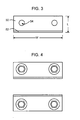
FIG. 3 is a simplified outer diameter (OD) view of a rail of the attachment ofFIG. 2 . -
FIG. 4 is a simplified outer diameter (OD) view of the attachment ofFIG. 2 . - Like reference numbers and designations in the various drawings indicate like elements.
- Referring to
FIG. 1 , agas turbine engine 10 includes a fan section 12, a low pressure compressor 14, ahigh pressure compressor 16, acombustor 18, alow pressure turbine 20, and ahigh pressure turbine 22. The fan section 12 and the low pressure compressor 14 are directly connected to one another and are driven by thelow pressure turbine 20. In some configurations, the fan section 12 is driven separately through a gearbox at a lower speed than thelow pressure turbine 20. Thehigh pressure compressor 16 is directly driven by thehigh pressure turbine 22. Air compressed by the fan section 12 will either enter the low pressure compressor 14 as "core gas flow" or will enter abypass passage 23 outside the engine core as "bypass air". Bypass air exiting the fan section 12 travels toward and impinges against a plurality of fanexit guide vanes 24, or "FEGV's", disposed about the circumference of theengine 10. The FEGV's 24 straighten and guide the bypass air into ducting (not shown) disposed outside theengine 10. - Now referring to
FIGS. 1 and 2 , the FEGV's 24 extend between faninner case 26 andouter case 28. Theinner case 26 is disposed radially between the low pressure compressor 14 and the FEGV's 24 and theouter case 26 is disposed radially outside of the FEGV's 24. Each FEGV 24 includes anairfoil 30 and means for attaching theairfoil 30 between the inner andouter cases - Referring specifically now to
FIG. 2 , each FEGV 24 may be attached to theouter case 26 by at least one rail, for example, afirst rail 32 and asecond rail 34, disposed about anexterior surface 36 of theouter case 28. By rail is meant an element which is elongate in a circumferential direction. Thefirst rail 32 andsecond rail 34 may be aligned approximately parallel to one another and secured to theouter case 28 by a first means for attaching 38 and a second means for attaching 40, respectively. Each means for attaching 38, 40 secure eachFEGV 24 to theouter case 28 and also secure eachrail outer case 28. The means for attaching 38, 40 may include at least one of the following: bolts, rivets, screws, and the like, as known to one of ordinary skill in the art. Preferably at least two circumferentially spaced apart means (e.g., nut, washer, and screw/bolt combinations) for attaching 38,40 are provided for eachrail 32,34 (e.g., a front pair and a rear pair). - The
rails outer case 28. As can be seen, eachrail first portion 50 which extends along the case 28 (and has holes for accommodating the associated means for attaching) and asecond portion 52 protruding radially outward. This second portion forms a stiffening flange for therail - The
rails outer case 28. As the FEGV vibrates, therails FEGV 24 from pulling the means for attaching through theouter case 28 as well as also prevent the case from cracking. A typical gas turbine engine contains approximately eighty (80) FEGV's, and thus approximately one hundred sixty (160) rails may be installed to stiffen the outer case and either mitigate existing cracking or cracks and/or prevent cracking from occurring. By stiffening the outer case, the entire turbine engine casing may be reinforced to withstand torsional modes of vibration experienced during operation of the turbine engine. - A pair of rails each having the following dimensions axial length L of 0.5 inches (12.7 millimeters) x radial height of 0.5 inches (12.7 millimeters) x width or length along the case circumference W of 3.0 inches (76.2 millimeters) and composed of 0.0625 inches (1.5875 millimeters) thick sheet metal were bolted to a piece of an outer case and an FEGV. The structure was mounted to a hydraulic cylinder and a simulated air load was applied. One cycle constituted one stroke actuated by the hydraulic cylinder upon the structure. After subjecting the structure to ten-thousand (10,000) cycles, no crack growth was observed in the outer case and the outer case maintained an overall stiffness of between approximately eighty percent (80%) to approximately one hundred percent (100%) of the original stiffness. Exemplary ranges for axial height and length are each 10-30, mm, more narrowly 12-20mm and for end-to-end width W 2.5-10cm, more narrowly 6-9cm.
- One or more embodiments of the present disclosure have been described. Nevertheless, it will be understood that various modifications may be made without departing from the scope of the disclosure. Accordingly, other embodiments are within the scope of the following claims.
Claims (15)
- A method for preventing cracking of a turbine engine case (28), comprising:disposing at least two rails (32,34) upon an exterior surface of a turbine engine case (28); andsecuring a first said rail (32) to a first means (38) for attaching at least one fan exit guide vane (24) to said turbine engine case (28) and securing a said second rail (34) to a second means (40) for attaching said at least one fan exit guide vane (24) to said turbine engine case (28).
- The method of claim 1, wherein disposing comprises the steps of:placing said first rail (32) in connection with said first means (38) for attaching;placing said second rail (34) in connection with said second means (40) for attaching; andaligning said first rail (32) approximately parallel to said second rail (34).
- The method of claim 1 or 2, wherein disposing further comprises disposing at least two circumferentially-shaped rails (32,34).
- The method of claim 1, 2 or 3, wherein:the at least one fan exit guide vane (24) comprises a plurality of fan exit guide vanes (24) and wherein the at least two rails (32,34) comprises a plurality of said first rails (32) and a plurality of said second rails (34); andthe securing comprises securing respective said first rails (32) to the first means of respective said fan exit guide vanes (24) and respective said second rails (34) to the second means of respective fan exit guide vanes (24).
- The method of any preceding claim, wherein each said rails (32,34) is formed of sheet metal and has an L-shaped cross-section with a first portion along the case (28) and a second portion protruding radially.
- A method for remanufacturing a turbine engine, comprising:replacing at least one means (38,40) for attaching at least one fan exit guide vane (30) to a turbine engine case (28) with at least one rail (32,34); andsecuring a first rail (32) to a first means (38) for attaching said at least one fan exit guide vane (24) to said turbine engine case (28) and securing a second rail (34) to a second means (40) for attaching said at least one fan exit guide vane (24) to said turbine engine case (28).
- The method of claim 6, wherein replacing comprises the steps of:placing said first rail (32) in connection with said first means (38) for attaching;placing said second rail (34) in connection with said second means (40) for attaching; andaligning said first rail (32) parallel to said second rail (34).
- A turbine engine, comprising:a fan section (12);a low pressure compressor (14); andan engine case (28) disposed about said fan section (12) and said low pressure compressor (14),wherein said engine case (28) comprises at least one rail (32,34) disposed upon an exterior surface and in connection with a first means (38.40) for attaching a fan exit guide vane (24) to said engine case (28) for reinforcing said engine case (28).
- The turbine engine of claim 8, wherein said at least one rail (32,34) further comprises a first rail (32) connected to said exterior surface and said first means (38) for attaching, and a second rail (34) connected to said exterior surface and a second means (40) for attaching.
- The turbine engine of claim 8 or 9, wherein said at least one rail comprises at least one circumferentially-shaped rail (32,34).
- The turbine engine of claim 10, wherein said at least one circumferentially-shaped rail (32,34) comprises a substantially circumferential shape that is complementary to said exterior surface of said engine case (28).
- The turbine engine of any of claims 8 to 11, wherein said at least one rail (32,34) has an L-shaped cross-section having a first portion along the case (28) and a second portion protruding radially outward.
- The turbine engine of any of claims 8 to 11 wherein said rail (32,34) comprises a radially protruding stiffening flange.
- The turbine engine of any of claims 8 to 12, wherein said at least one rail comprises a plurality of first rails (32) each respectively connected to the first means (38) of an associated said fan exit guide vane (24), and, optionally a plurality of second rails (34) each respectively connected to a second means (40) for attaching of the associated fan exit guide vane (30).
- The turbine of any of claims 8 to 14 wherein the or each rail (32,34) is attached to said engine case (28) and the fan exit guide vane (24) by at least two circumferentially spaced attachment means (38,40).
Applications Claiming Priority (2)
| Application Number | Priority Date | Filing Date | Title |
|---|---|---|---|
| US12/333,613 US20100150711A1 (en) | 2008-12-12 | 2008-12-12 | Apparatus and method for preventing cracking of turbine engine cases |
| US12/635,131 US8662819B2 (en) | 2008-12-12 | 2009-12-10 | Apparatus and method for preventing cracking of turbine engine cases |
Publications (2)
| Publication Number | Publication Date |
|---|---|
| EP2196627A2 true EP2196627A2 (en) | 2010-06-16 |
| EP2196627A3 EP2196627A3 (en) | 2013-12-04 |
Family
ID=42077894
Family Applications (1)
| Application Number | Title | Priority Date | Filing Date |
|---|---|---|---|
| EP09252774.6A Withdrawn EP2196627A3 (en) | 2008-12-12 | 2009-12-14 | Apparatus and method for preventing cracking of turbine engine cases |
Country Status (2)
| Country | Link |
|---|---|
| US (1) | US8662819B2 (en) |
| EP (1) | EP2196627A3 (en) |
Families Citing this family (7)
| Publication number | Priority date | Publication date | Assignee | Title |
|---|---|---|---|---|
| US8662819B2 (en) | 2008-12-12 | 2014-03-04 | United Technologies Corporation | Apparatus and method for preventing cracking of turbine engine cases |
| US20100150711A1 (en) * | 2008-12-12 | 2010-06-17 | United Technologies Corporation | Apparatus and method for preventing cracking of turbine engine cases |
| FR2958980B1 (en) * | 2010-04-14 | 2013-03-15 | Snecma | RECTIFIER DEVICE FOR TURBOMACHINE |
| US9470243B2 (en) * | 2011-03-09 | 2016-10-18 | Ihi Corporation | Guide vane attachment structure and fan |
| EP3068981B1 (en) | 2013-11-14 | 2022-08-17 | Raytheon Technologies Corporation | Flange relief for split casing |
| US10519863B2 (en) | 2014-12-04 | 2019-12-31 | United Technologies Corporation | Turbine engine case attachment and a method of using the same |
| US12158076B1 (en) * | 2023-07-07 | 2024-12-03 | Pratt & Whitney Canada Corp. | Local stiffening for gas turbine engine casing |
Family Cites Families (25)
| Publication number | Priority date | Publication date | Assignee | Title |
|---|---|---|---|---|
| CH270334A (en) * | 1945-01-16 | 1950-08-31 | Power Jets Res & Dev Ltd | Blade carrier in axial centrifugal machines. |
| GB695724A (en) * | 1950-08-01 | 1953-08-19 | Rolls Royce | Improvements in or relating to structural elements for axial-flow turbo-machines such as compressors or turbines of gas-turbine engines |
| US4815940A (en) | 1986-08-04 | 1989-03-28 | United Technologies Corporation | Fatigue strengthened composite article |
| US5354174A (en) * | 1990-09-12 | 1994-10-11 | United Technologies Corporation | Backbone support structure for compressor |
| US5127797A (en) * | 1990-09-12 | 1992-07-07 | United Technologies Corporation | Compressor case attachment means |
| US5118253A (en) * | 1990-09-12 | 1992-06-02 | United Technologies Corporation | Compressor case construction with backbone |
| US5224824A (en) * | 1990-09-12 | 1993-07-06 | United Technologies Corporation | Compressor case construction |
| US5131811A (en) * | 1990-09-12 | 1992-07-21 | United Technologies Corporation | Fastener mounting for multi-stage compressor |
| US5236303A (en) * | 1991-09-27 | 1993-08-17 | General Electric Company | Gas turbine engine structural frame with multi-clevis ring attachment of struts to outer casing |
| CA2200053C (en) | 1994-10-13 | 2005-02-22 | The Boeing Company | Jet engine fan noise reduction system utilizing electro-pneumatic transducers |
| US5873699A (en) | 1996-06-27 | 1999-02-23 | United Technologies Corporation | Discontinuously reinforced aluminum gas turbine guide vane |
| EP1018524B1 (en) | 1998-12-29 | 2011-08-17 | United Technologies Corporation | Use of a mixable room temperature castable polyurethane system |
| US6619917B2 (en) | 2000-12-19 | 2003-09-16 | United Technologies Corporation | Machined fan exit guide vane attachment pockets for use in a gas turbine |
| RU2272151C2 (en) * | 2000-12-28 | 2006-03-20 | Альстом Текнолоджи Лтд | Axial-flow turbine stator blade |
| US6554564B1 (en) | 2001-11-14 | 2003-04-29 | United Technologies Corporation | Reduced noise fan exit guide vane configuration for turbofan engines |
| US7334998B2 (en) | 2003-12-08 | 2008-02-26 | The United States Of America As Represented By The Administrator Of The National Aeronautics And Space Administration | Low-noise fan exit guide vanes |
| EP1548233B1 (en) * | 2003-12-18 | 2006-08-02 | Techspace Aero S.A. | Fastening device for stator blades and compressor stator stage comprising such a fastening device |
| US7192245B2 (en) * | 2004-12-03 | 2007-03-20 | Pratt & Whitney Canada Corp. | Rotor assembly with cooling air deflectors and method |
| US20070122274A1 (en) * | 2005-11-29 | 2007-05-31 | General Electric Company | Tip shroud attachment for stator vane |
| US7614848B2 (en) | 2006-10-10 | 2009-11-10 | United Technologies Corporation | Fan exit guide vane repair method and apparatus |
| SE0700823L (en) * | 2007-03-30 | 2008-10-01 | Volvo Aero Corp | Component for a gas turbine engine, a jet engine equipped with such a component, and an airplane equipped with such a jet engine |
| US8347633B2 (en) | 2007-07-27 | 2013-01-08 | United Technologies Corporation | Gas turbine engine with variable geometry fan exit guide vane system |
| US7854583B2 (en) * | 2007-08-08 | 2010-12-21 | Genral Electric Company | Stator joining strip and method of linking adjacent stators |
| FR2923530B1 (en) * | 2007-11-09 | 2014-04-04 | Snecma | CONNECTION OF RADIAL ARMS TO A CIRCULAR VIROLE BY AXES AND SPACERS |
| US8662819B2 (en) | 2008-12-12 | 2014-03-04 | United Technologies Corporation | Apparatus and method for preventing cracking of turbine engine cases |
-
2009
- 2009-12-10 US US12/635,131 patent/US8662819B2/en not_active Expired - Fee Related
- 2009-12-14 EP EP09252774.6A patent/EP2196627A3/en not_active Withdrawn
Non-Patent Citations (1)
| Title |
|---|
| None |
Also Published As
| Publication number | Publication date |
|---|---|
| EP2196627A3 (en) | 2013-12-04 |
| US8662819B2 (en) | 2014-03-04 |
| US20100196149A1 (en) | 2010-08-05 |
Similar Documents
| Publication | Publication Date | Title |
|---|---|---|
| US8662819B2 (en) | Apparatus and method for preventing cracking of turbine engine cases | |
| JP5591944B2 (en) | Installation of AGB in the intermediate casing for the turbojet fan compartment | |
| CA2600818C (en) | Exhaust duct and tail cone attachment of aircraft engines | |
| US11008887B2 (en) | Fan containment assembly having a nesting cavity | |
| EP1911931A2 (en) | Fan exit guide vane and method of repairing therof | |
| US20110138769A1 (en) | Fan containment case | |
| US7871243B2 (en) | Augmented vaneless diffuser containment | |
| US20090321178A1 (en) | Method and system for damped acoustic panels | |
| JP2007500298A (en) | Turbofan case and manufacturing method | |
| JPH05248265A (en) | Damper assembly for strut for gas turbine engine | |
| EP3153680A1 (en) | Gas turbine gearbox input shaft | |
| EP3379056B1 (en) | Two-shaft tower shaft support and mounting method | |
| US20100150711A1 (en) | Apparatus and method for preventing cracking of turbine engine cases | |
| US9151181B2 (en) | Metallic rails on composite fan case | |
| US20160201482A1 (en) | Aluminum airfoil with titanium coating | |
| US20080159854A1 (en) | Methods and apparatus for fabricating a fan assembly for use with turbine engines | |
| EP2855898B1 (en) | Stator vane bumper ring | |
| US10724390B2 (en) | Collar support assembly for airfoils | |
| US6881032B2 (en) | Exit stator mounting | |
| US20200063564A1 (en) | Turbulent air reducer for a gas turbine engine | |
| EP1536101A2 (en) | Turbine drum rotor for a turbine engine and method of installation | |
| US9045984B2 (en) | Stator vane mistake proofing | |
| US10533449B2 (en) | Containment for a continuous flow machine | |
| KR20010101722A (en) | Repair of turbine exhaust case | |
| GB2375798A (en) | A gas turbine engine fan blade containment assembly |
Legal Events
| Date | Code | Title | Description |
|---|---|---|---|
| PUAI | Public reference made under article 153(3) epc to a published international application that has entered the european phase |
Free format text: ORIGINAL CODE: 0009012 |
|
| AK | Designated contracting states |
Kind code of ref document: A2 Designated state(s): AT BE BG CH CY CZ DE DK EE ES FI FR GB GR HR HU IE IS IT LI LT LU LV MC MK MT NL NO PL PT RO SE SI SK SM TR |
|
| AX | Request for extension of the european patent |
Extension state: AL BA RS |
|
| PUAL | Search report despatched |
Free format text: ORIGINAL CODE: 0009013 |
|
| AK | Designated contracting states |
Kind code of ref document: A3 Designated state(s): AT BE BG CH CY CZ DE DK EE ES FI FR GB GR HR HU IE IS IT LI LT LU LV MC MK MT NL NO PL PT RO SE SI SK SM TR |
|
| AX | Request for extension of the european patent |
Extension state: AL BA RS |
|
| RIC1 | Information provided on ipc code assigned before grant |
Ipc: F01D 9/04 20060101AFI20131030BHEP Ipc: F01D 25/24 20060101ALI20131030BHEP |
|
| STAA | Information on the status of an ep patent application or granted ep patent |
Free format text: STATUS: THE APPLICATION IS DEEMED TO BE WITHDRAWN |
|
| 18D | Application deemed to be withdrawn |
Effective date: 20140605 |