EP2196572B1 - Lower thread tension control device - Google Patents
Lower thread tension control device Download PDFInfo
- Publication number
- EP2196572B1 EP2196572B1 EP09176975A EP09176975A EP2196572B1 EP 2196572 B1 EP2196572 B1 EP 2196572B1 EP 09176975 A EP09176975 A EP 09176975A EP 09176975 A EP09176975 A EP 09176975A EP 2196572 B1 EP2196572 B1 EP 2196572B1
- Authority
- EP
- European Patent Office
- Prior art keywords
- thread
- bobbin case
- tensioning spring
- lower thread
- support member
- Prior art date
- Legal status (The legal status is an assumption and is not a legal conclusion. Google has not performed a legal analysis and makes no representation as to the accuracy of the status listed.)
- Active
Links
- 239000000696 magnetic material Substances 0.000 claims abstract description 10
- 230000008859 change Effects 0.000 claims abstract description 8
- 230000005291 magnetic effect Effects 0.000 claims description 35
- 238000009958 sewing Methods 0.000 description 41
- 230000036316 preload Effects 0.000 description 11
- 230000006870 function Effects 0.000 description 5
- XEEYBQQBJWHFJM-UHFFFAOYSA-N Iron Chemical group [Fe] XEEYBQQBJWHFJM-UHFFFAOYSA-N 0.000 description 4
- 230000007246 mechanism Effects 0.000 description 4
- 239000000463 material Substances 0.000 description 3
- 229910001566 austenite Inorganic materials 0.000 description 2
- 230000015572 biosynthetic process Effects 0.000 description 2
- 230000004907 flux Effects 0.000 description 2
- 229910001220 stainless steel Inorganic materials 0.000 description 2
- 239000010935 stainless steel Substances 0.000 description 2
- 238000004804 winding Methods 0.000 description 2
- 229910052782 aluminium Inorganic materials 0.000 description 1
- XAGFODPZIPBFFR-UHFFFAOYSA-N aluminium Chemical compound [Al] XAGFODPZIPBFFR-UHFFFAOYSA-N 0.000 description 1
- 239000000919 ceramic Substances 0.000 description 1
- 238000010586 diagram Methods 0.000 description 1
- 239000013013 elastic material Substances 0.000 description 1
- 239000004744 fabric Substances 0.000 description 1
- 239000003302 ferromagnetic material Substances 0.000 description 1
- 238000010438 heat treatment Methods 0.000 description 1
- 229910052742 iron Inorganic materials 0.000 description 1
- 229910052751 metal Inorganic materials 0.000 description 1
- 239000002184 metal Substances 0.000 description 1
- 230000004048 modification Effects 0.000 description 1
- 238000012986 modification Methods 0.000 description 1
- 238000012856 packing Methods 0.000 description 1
- 230000009467 reduction Effects 0.000 description 1
- 239000011347 resin Substances 0.000 description 1
- 229920005989 resin Polymers 0.000 description 1
Images


Classifications
-
- D—TEXTILES; PAPER
- D05—SEWING; EMBROIDERING; TUFTING
- D05B—SEWING
- D05B57/00—Loop takers, e.g. loopers
- D05B57/26—Bobbin holders or casings; Bobbin holder or case guards; Bobbin discharge devices
Definitions
- the present invention relates to a lower thread tension control device adapted to control a tension of a lower thread to be drawn out from a bobbin case of a sewing machine, (see JP-A-2009 261 551 and JP- A- 2009 261 550 ).
- a needle drive mechanism which causes a sewing needle to reciprocate in the up-down direction
- a shuttle mechanism including a shuttle for forming stitches in cooperation with the sewing needle inside a bed of a sewing machine frame
- the shuttle includes an outer shuttle which is driven to rotate, an inner shuttle which is held inside the outer shuttle so as not to rotate, and a bobbin case which is removably fitted to the inner shuttle, and the bobbin case houses a bobbin around which a lower thread is wound.
- the lower thread to be drawn out from the bobbin is supplied by an appropriate amount depending on sewing conditions.
- the bobbin case is provided with, for example, as shown in Fig. 10 , a member which adjusts the tension of the lower thread.
- a thread tensioning spring (leaf spring) 102 is attached by a fixation screw 103, a lower thread T (see Fig. 13 ) is disposed between the thread tensioning spring 102 and the bobbin case 101, and by pressing the lower thread by the thread tensioning spring 102, a tension is applied to the lower thread.
- a thread pressing portion 102a of the thread tensioning spring 102 is separated from the outer circumferential surface 101a of the bobbin case 101 at a distance greater than the distance at which the thread pressing portion 102a holds the lower thread onto the outer circumferential surface 101a of the bobbin case 101.
- the lower thread is not held between the thread pressing portion 102a of the thread tensioning spring 102 and the outer circumferential surface 101a of the bobbin case 101.
- the thread pressing portion 102a of the thread tensioning spring 102 contacts the outer circumferential surface 101a of the bobbin case 101 (a preload from the adjust screw exists). Accordingly, the lower thread is pinched, and a frictional force is generated when the lower thread is drawn out, and the lower thread is tensioned.
- the tension of the lower thread in the bobbin case 101 is adjusted after removing the bobbin case 101 from the shuttle, by turning the adjust screw 104 with a screwdriver.
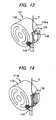
- a thread tensioning spring (a leaf spring) 113 made of a magnetic material is provided on the outer circumferential surface 112a of the bobbin case 112, an electromagnet 114 is provided on the outer side surface of a shuttle (not shown) outside the bobbin case 112 in the vicinity of the thread tensioning spring 113, and this electromagnet 114 is supplied with a current in accordance with a sewing speed.
- the thread tensioning spring 113 of a magnetic material is attracted toward the electromagnet 114. Accordingly, as shown by two-dotted chain lines in Figs. 13 and 14 , the thread tensioning spring 113 is moved in a direction of separating from or approaching the outer circumferential surface 112a of the bobbin case 112. That is, the tension of the lower thread T can be adjusted in real time in the range of an initial tension, so that the tension of the lower thread T to be pulled out from the bobbin can be adjusted even while sewing.
- a thread inserting slit 115 which guides the lower thread T to a thread hole (not shown) so as to pull the lower thread T out from the inside to the outside of the bobbin case 112 is provided, whereas on the outer circumferential surface 112a of the bobbin case 112 of the lower thread tension control device 111 A shown in Fig. 14 , the thread inserting slit 115 is not formed.
- the tension of the lower thread cannot be varied during operation of the sewing machine, so that, for example, the tension of the lower thread cannot be adjusted to be proper when the thickness of cloth changes while sewing.
- the sewing stitch type cannot be changed between whip stitches and purl stitches, for example.
- the conventional lower thread tension control devices 111 and 111A shown in Figs. 13 and 14 which can automatically adjust the tension do not have an adjusting function of adjusting the initial tension of the lower thread T like the thread tensioning spring 102 of the bobbin case 101, and thus cannot adjust the initial tension of the lower thread T.
- the conventional lower thread tension control devices 111 and 111A are configured such that the thread tensioning spring 113 is attracted by the electromagnet 114 provided on the outer side surface of the shuttle, and the distance that separates the electromagnet 114 and the thread tensioning spring 113 is great, and the magnetic force, generation direction is not toward the thread tensioning spring 113. Therefore, the generation efficiency of the magnetic attractive force is low, that is, the magnetic resistance is high, and the magnetic fluxes cannot be concentrated, and a sufficient magnetic attractive force is not generated, so that the variable range of the tension of the lower thread T is narrow.
- the electromagnet 114 is increased in size to increase the magnetic attractive force, when replacing the bobbin, the electromagnet 114 obstructs the replacement and deteriorates the operability, and the magnetic attractive force to be applied to the shuttle, the bobbin, and the bobbin case 112, etc., is also increased, and the thread pull-up resistance when the upper thread comes out from the inner shuttle increases and the upper thread cannot be sufficiently pulled up, and the sewing quality is deteriorated.
- the thread tensioning spring 113 is directly fixed to the bobbin case 112, so that depending on individual differences of the fixed position of the thread tensioning spring 113 and the curvature of the thread tensioning spring 113, the tension widely varies. To reduce the tension variation, a tension controllable range must be individually measured, and the tension adjustment takes time.
- a first aspect of the present invention provides a lower thread tension control device including:
- the force of pressing the lower thread by the thread pressing portion of the thread tensioning spring can be controlled, so that the tension to be applied to the lower thread can easily and reliably be controlled even during operation of the sewing machine.
- the force of pressing the lower thread by the thread pressing portion of the thread tensioning spring can also be adjusted by the screwing amount of the adjust screw, so that the initial tension to be applied to the lower thread can easily and reliably be controlled.
- the initial tension to be applied to the lower thread and the tension to be applied to the lower thread during the operation of the sewing machine can easily and reliably be changed individually.
- the tension of the lower thread can reliably and easily be changed when needed.
- the electromagnet is disposed to face the bottom wall substitute portion.
- a lower thread tension control device is used in a sewing machine with a horizontal full rotary shuttle such as a lockstitch sewing machine.
- a sewing machine M to which the lower thread tension control device 1 of the embodiment is attached includes a sewing machine arm MA including a known needle drive mechanism (not shown), and a sewing machine bed MB including a known shuttle drive mechanism (not shown).
- a horizontal shuttle 2 which is a horizontal full rotary shuttle as a shuttle is disposed on the left side in Fig. 1 of the sewing machine bed MB, and an outer shuttle 3 ( Fig. 2 ) of the horizontal shuttle 2 is driven to rotate in synchronization with up-down movements of the sewing needle N.
- the lower thread pension control device 1 of the embodiment is disposed in the horizontal shuttle 2.
- this horizontal shuttle 2 includes an outer shuttle 3 to be driven to rotate around a rotation axis center RL extending horizontally, and an inner shuttle 4 held while being stopped from rotating inside the outer shuttle 3.
- the inner shuttle 4 is prevented by an inner shuttle stopper as an inner shuttle rotation stopper attached to the sewing machine frame (both are not shown) from following the rotation of the outer shuttle 3 when the outer shuttle 3 rotates.
- a bobbin case 11 to be fitted to the inner shuttle 4 has a bottomed cylindrical shape as a whole, and inside this, a bobbin around which a lower thread T is wound is housed rotatably and removably from the opening end.
- the bobbin case 11 may be made of a magnetic material or a nonmagnetic material, but for efficiently driving a support member 17 by a magnetic force, the bobbin case 11 is preferably made of a nonmagnetic material such as a resin, nonferrous metal, austenite-based stainless steel, aluminum, and ceramics.
- the bobbin case 11 is fitted so that its opening end is opposed to the shuttle bottom surface exposed to the outside of the inner shuttle 4, and is disposed so that the outer surface of the bottom portion of the bobbin case 11 is exposed to the outside.
- a thread hole 12 and a thread inserting slit 13 communicating with the thread hole 12 are formed, and by sliding one end of the lower thread T into a slit entrance 13a of the thread inserting slit 13 provided on the opening end side of the bobbin case 11, the lower thread T is led to the outside from the inside of the bobbin case 11 via the thread hole 12, specifically, led to the outer circumferential surface 11b of the bobbin case 11.
- a thread tensioning spring 14 provided on a support member 17 is disposed on the outer circumferential surface 11b of the bobbin case 11.
- the thread tensioning spring 14 is for applying tension to the lower thread T by pressing the lower thread T to be pulled outside of the bobbin case 11 from the bobbin via the thread hole 12, and includes a thread pressing portion 14a disposed so as to cover the thread hole 12 and a fixing portion 14b disposed away (downwardly away in Fig. 2 ) from the thread pressing portion 14a.
- the thread tensioning spring 14 is removably attached to the bobbin case 11 by a fixation screw 15 screwed to the support member 17 described later via the fixing portion 14b.
- an opening 16 (a hatched region in Fig. 6 ) which makes the inside of the bobbin case 11 communicate with the outside is formed.
- This opening 16 is formed at a position which is near the formation portion of the thread hole 12 of the bobbin case 11 so as not to interfere with the thread inserting slit 13 ( Fig. 4 , Fig. 6 ).
- the support member 17 made of a magnetic material, preferably, a ferromagnetic material is disposed to form a part of the bobbin case 11.
- This support member 17 includes an arc-shaped circumferential wall substitute portion 17a forming (substituting for) a part of the circumferential wall 11a of the bobbin case 11, and a flat-shaped bottom wall substitute portion 17b forming (substituting for) a part of the bottom wall 11c of the bobbin case 11, and has a substantially L-shaped section as a whole.
- a support shaft 18 is inserted in the bent portion between the circumferential wall substitute portion 17a and the bottom wall substitute portion 17b of the support member 17. As shown in Fig. 4 , this support shaft 18 is disposed on an axis line orthogonal to the axial direction of the bobbin case 11 and the orthogonal line A-A passing through the axis, and both ends of the support shaft 18 are fitted in and attached to the vicinity of the opening 16 of the bobbin case 11.
- the support member 17 is supported so as to be rotatable around the support shaft 18.
- an adjust screw 19 is screwed via the intermediate portion 14c between the thread pressing portion 14a and the fixing portion 14b of the thread tensioning spring 14. Further, to the circumferential wall substitute portion 17a of the support member 17, the fixation screw 15 is screwed via the fixing portion 14b disposed away from the thread pressing portion 14a of the thread tensioning spring 14. That is, as described above, the thread tensioning spring 14 is removably attached to the bobbin case 11 by the fixation screw 15 screwed to the support member 17 via the fixing portion 14b.
- the thread tensioning spring 14, the fixed screw 15, the support shaft 18, and the adjust screw 19 may be made of a magnetic material or a nonmagnetic material such as austenite-based stainless steeL
- the thread tensioning spring means 70 turnable for pressing the thread pressing portion 14a of the thread tensioning spring 14 to the outer circumferential surface 11b of the bobbin case 11 of the embodiment consists of the thread tensioning spring 14, the fixation screw 15, the support member 17, the support shaft 18, and the adjust screw 19.
- an elastic member which functions as a loosening stopper for the adjust screw 19 may be disposed between the thread tensioning spring 14 and the portion opposed to the thread tensioning spring 14 of the support member 17, an elastic member which functions as a loosening stopper for the adjust screw 19 may be disposed.
- a washer such as a conical spring washer or a spring washer, or an annular packing made of an elastic material such as rubber may be used.
- a stopper 21 for limiting a turning range of the support member 17 when turning around the support shaft 18 is formed.
- the bobbin case 11 is provided with a stopper 21 for limiting a movable range of the thread tensioning spring means 20.
- This stopper 21 includes a first stopper 21a formed on the outer surface of the bottom wall 11c of the bobbin case 11, and a second stopper 21b formed by an opening end of the circumferential wall 11a of the bobbin case 11.
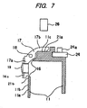
- the first stopper 21 a restricts a maximum position of clockwise rotation in Fig. 7 of the support member 17 around the support shaft 18.
- the second stopper 21b restricts a maximum position of counterclockwise rotation in Fig. 7 of the support member 17 around the support shaft 18.
- the support member 17 is formed so as to normally hold a state in which the bottom wall substitute portion 17b is in contact with the first stopper 21a by a spring force of the thread tensioning spring 14.
- a known latch 24 for holding the bobbin case 11 so as to prevent the bobbin case 11 from coming off the inner shuttle 4 is provided, and this latch 24 is provided with a latch lever 24a for releasing the state held by the latch 24 of the bobbin case 11 when removing the bobbin case 11 fitted to the inner shuttle 4.
- an electromagnet 26 is disposed to face the bottom wall substitute portion 17b of the support member 17.
- This electromagnet 26 includes an iron core 26a made of a magnetic material such as soft iron, and a coil 26b around which an insulated electric wire is closely wound ( Fig. 2 ).
- the electromagnet 26 is supported on the sewing machine frame or a support stay attached to the sewing machine frame not shown so that the longitudinal direction of the iron core 26a extends horizontally.
- a side view of the electromagnet 26 is shown in Fig. 1 .
- the electromagnet 26 is electrically connected to a control section 31 including a CPU 32 which functions as an arithmetic section and a memory 33 which functions as a storage section, etc., and based on control commands sent out from the control section 31, a timing of switching between an energized state and an non-energized state of the electromagnet 26, that is, the coil 26b, the energization time, and a current value during energization, etc., are controlled ( Fig. 2 ).
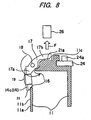
- a magnetic attractive force F is generated between the electromagnet 26 and the bottom wall substitute portion 17b of the support member 17, and this magnetic attractive force F rotates the support member 17 counterclockwise in Fig. 7 around the support shaft 18.
- a maximum position of the rotation of the support member 17 by the magnetic attractive force F is restricted by contact of the circumferential wall substitute portion 17a with the second stopper 21b.
- a state in which the circumferential wall substitute portion 17a of the support member 17 comes into contact with the second stopper 21b by energizing the electromagnet 26 is shown in Fig. 8 along with the application direction of the magnetic attractive force F.
- the support member 17 restores to the original state where the bottom wall substitute portion 17b is in contact with the first stopper 21a.
- the remaining configuration of the bobbin case 11 is the same as conventionally known, so that detailed description thereof is omitted.
- the lower thread tension control device 1 of the embodiment has two modes of a non-energized state where the coil 26b of the electromagnet 26 is not energized and an energized state.
- a spring force of the thread tensioning spring 14 is applied to the support member 17 and holds a state in which the bottom wall substitute portion 17b is in contact with the first stopper 21a.
- the thread tensioning spring 14 presses a portion including the thread hole 12 of the bobbin case 11 by the thread pressing portion 14a, and applies a fixed initial tension to the lower thread T to be pulled out from the bobbin via the thread hole 12.
- the warp amount of the thread tensioning spring 14 is adjusted by a tightening amount of the adjust screw 19.
- the adjust screw 19 is preloaded by a reactive force depending on the warp amount of the thread tensioning spring 14. When this preload is not applied or small, the adjust screw 19 is loosened by vibrations during operation of the sewing machine, and the tension to be applied to the lower thread T is reduced and the adjust screw 19 comes off.
- the adjust screw 19 needs to be tightened until it is sufficiently preload by the reactive force of the thread tensioning spring 14.
- the thread tensioning spring 102 is sufficiently separated from the outer circumferential surface 101a of the bobbin case 101 at a distance greater than the distance at which the thread tensioning spring 102 holds the lower thread onto the outer circumferential surface 101a of the bobbin case 101, so that the lower thread T is not tensioned.
- the thread tensioning spring 102 comes closer to the outer circumferential surface 101a of the bobbin case 101 and comes into contact with this, and accordingly, the thread tensioning spring 104 pinches the lower thread T, and a frictional force with the lower thread T is generated, and the lower thread is tensioned.
- the lower thread tension is not generated until the force applied to the portion of the thread tensioning spring 102, at which the adjust screw 104 is attached, reaches the force 1, and when the applied force exceeds the force 1, the thread tensioning spring 102 can hold the lower thread T onto the outer circumferential surface 101a of the bobbin case 101, so that the lower thread tension increases as the applied force is further increased.
- the fixation screw 15 and the adjust screw 19 are attached to the support member 17, so that the preload of the adjust screw 19 due to the reactive force of the thread tensioning spring 14 is canceled out by the intermediate portion 14c provided on the support member 17, so that the preload does not affect the force applied to the thread tensioning spring 14. Therefore, as shown in the tension characteristic 2 of Fig. 9 (tension characteristic according to embodiment of the present invention), the lower thread tension is already generated when the applied force is zero, and the force to be applied in order to obtain the required lower thread tension variable range is the force 2 at a maximum. That is, the force to be applied in order to obtain a certain lower thread tension variable range can be reduced by an amount corresponding to a difference between the force 1A and the force 2, and the efficiency of lower thread tension generation is improved.
- the initial tension to be applied to the lower thread T can be adjusted by turning the adjust screw 19 by a screwdriver by removing the bobbin case 11 from the sewing machine after stopping the sewing machine in the same manner as in the case of the conventional bobbin case 101.
- the configuration of the bobbin case 11 is similar to the conventional bobbin case 101 except that the bobbin case 11 is provided with the support member 17, and the fixation screw 15 and the adjust screw 19 are screwed to the support member 17, and therefore, for setting the tightening amount of the adjust screw 19, the adjustment experiences of the tension of the lower thread T in the bobbin-case 101 including the thread tensioning spring 102 can be utilized.
- a magnetic attractive force F shown by a thick arrow in Fig. 8 is generated between the electromagnet 26 and the bottom wall substitute portion 17b of the support member 17. Then, when the magnetic attractive force F exceeds the spring force of the initial tension of the thread tensioning spring 14, an angle of counterclockwise rotation shown by the arrow in Fig. 8 of the support member 17 around the support shaft 18 is determined based on the magnetic attractive force F and a spring constant of the thread tensioning spring 14, and the support member 17 pushes the intermediate portion 14c of the thread tensioning spring 14 toward the center of the bobbin case 11 as much as the angle.
- the thread tensioning spring 14 warps and the force of pressing the lower thread T by the thread pressing portion 14a increases, and the frictional force of the lower thread T pinched between the thread pressing portion 14a of the thread tensioning spring 14 and the outer circumferential surface 11b of the bobbin case 11 increases, and the tension of the lower thread T also increases.
- the magnetic force of the electromagnet 26 that is, the strength and weakness of the magnetic force of the electromagnet 26 can be changed. Therefore, by changing the current value to be supplied to the coil 26b, the force of pressing the lower thread T by the thread pressing portion 14a of the thread tensioning spring 14 changes, so that the tension of the lower thread T also changes.
- the tension of the lower thread T can be increased or reduced. This increase and reduction of the tension of the lower thread T are possible even while sewing.
- the support member 17 is configured so as to form a part of the bobbin case 11, so that the outer diameter size of the bobbin case 11 does not become larger and the inner diameter size of the bobbin case 11 does not become smaller.
- the ordinary bobbin can be used, so that the thread winding amount of the lower thread T around the bobbin does not change from the ordinary amount, and the frequency of replacement of the bobbin does not change from the ordinary frequency.
- the lower thread tension control device 1 of the embodiment can be used in an existing sewing machine.
- the lower thread tension control device 1 of the embodiment includes a thread tensioning spring means which presses the thread pressing portion 14a of the thread tensioning spring 14 to the outer circumferential surface 11a of the bobbin case 11.
- the thread tensioning spring means includes a support member 17 made of a magnetic material so as to have an L-shaped section by the circumferential wall substitute portion 17a forming a part of the circumferential wall of the bobbin case 11 and the bottom wall substitute portion 17b forming a part of the bottom wall continued to the circumferential wall of the bobbin case 11, the fixation screw 15 to be screwed to the support member 17 via a fixing portion 14b disposed away from the thread pressing portion 14a of the thread tensioning spring 14, the adjust screw 19 to be screwed to the support member 17 via the intermediate portion 14c between the thread pressing portion 14a and the fixing portion 14b of the thread tensioning spring 14, and the support shaft 18 which has ends attached to the bobbin case 11, and is inserted in the bent portion of the support member 17.
- the support member 17 is rotatable around the support shaft 18.
- the force of pressing the lower thread T by the thread pressing portion 14a of the thread tensioning spring 14 can be controlled by a screwing amount of the adjust screw 19, so that the initial tension to be applied to the lower thread T can easily and reliably be controlled.
- the lower thread tension control device 1 of the embodiment described above by changing the current to be supplied to the electromagnet 26, the force of pressing the lower thread T by the thread pressing portion 14a of the thread tensioning spring 14 can be controlled, so that the tension to be applied to the lower thread T can easily and reliably be controlled even during operation of the sewing machine.
- the initial tension to be applied to the lower thread T and the tension to be applied to the lower thread T during operation of the sewing machine can be easily and reliably varied individually.
- the tension of the lower thread T can be reliably and easily changed when needed.
- the lower thread tension control device 1 of the embodiment is configured such that the distance between the electromagnet 26 and the support member 17, to which the magnetic attractive force F is applied, is short, and the magnetic force generation direction is in the application direction of the magnetic attractive force F, and therefore, the magnetic force generation efficiency is very high, and the thrust of the preload from the adjust screw 19, which adjusts the initial tension, is not to be influenced by the tension control, so that a high tension can be variably controlled with a very small magnetic attractive force.
- the magnetic attractive force F necessary for varying the lower thread tension can be small, and the magnetic flux influence range is limited, so that the magnetic attractive force F to be applied to the bobbin case 11 and the inner shuttle 4 can be small, and the influence on the sewing quality is small.
- the current to be supplied to the electromagnet 26 can be small, so that the heating and power consumption of the electromagnet 26 can be reduced, and an energy-saving configuration can be realized.
- the bobbin case 11 is provided with the stopper 21 which limits the movable range of the thread tensioning spring means, so that the thread tensioning spring means can be reliably prevented from coming into contact with the bobbin housed inside the bobbin case 11 and the lower thread T.
- the initial tension to be applied to the lower thread T can be controlled by a screwing amount of the adjust screw 19, so that the operation of adjusting the initial tension to be applied to the lower thread T is possible as in the bobbin case 101, conventional adjustment information can also be utilized, and parts such as magnets whose characteristics are very different individually are not used, so that the initial tension scattering can be easily reduced by adjustment.
- the bobbin case 11 is provided with a thread inserting slit 13, so that it is convenient for an operator who performs a threading operation.
Landscapes
- Engineering & Computer Science (AREA)
- Textile Engineering (AREA)
- Sewing Machines And Sewing (AREA)
- Tension Adjustment In Filamentary Materials (AREA)
Abstract
Description
- The present invention relates to a lower thread tension control device adapted to control a tension of a lower thread to be drawn out from a bobbin case of a sewing machine, (see
JP-A-2009 261 551 JP- A- 2009 261 550 - Conventionally, in a so-called lockstitch sewing machine, a needle drive mechanism which causes a sewing needle to reciprocate in the up-down direction, and a shuttle mechanism including a shuttle for forming stitches in cooperation with the sewing needle inside a bed of a sewing machine frame, are provided. The shuttle includes an outer shuttle which is driven to rotate, an inner shuttle which is held inside the outer shuttle so as not to rotate, and a bobbin case which is removably fitted to the inner shuttle, and the bobbin case houses a bobbin around which a lower thread is wound.
- As compared with an upper thread (a needle thread), it is desirable that the lower thread to be drawn out from the bobbin is supplied by an appropriate amount depending on sewing conditions.
- Therefore, the bobbin case is provided with, for example, as shown in
Fig. 10 , a member which adjusts the tension of the lower thread. - In
Fig. 10 , to the outercircumferential surface 101a of thebobbin case 101, a thread tensioning spring (leaf spring) 102 is attached by afixation screw 103, a lower thread T (seeFig. 13 ) is disposed between thethread tensioning spring 102 and thebobbin case 101, and by pressing the lower thread by thethread tensioning spring 102, a tension is applied to the lower thread. In thisbobbin case 101, by adjusting the level of tightening anadjust screw 104 which tightens thethread tensioning spring 102, the warp of thethread tensioning spring 102 is adjusted, and the frictional force of the lower thread pinched between thethread tensioning spring 102 and the outercircumferential surface 101a of thebobbin case 101 is varied to adjust the tension applied to the lower thread. - Specifically, in the
bobbin case 101, as shown inFig. 11 , in a case in which a preload is not applied from the adjust screw 104 (no preload from the adjust screw), a thread pressing portion 102a of thethread tensioning spring 102 is separated from the outercircumferential surface 101a of thebobbin case 101 at a distance greater than the distance at which the thread pressing portion 102a holds the lower thread onto the outercircumferential surface 101a of thebobbin case 101. In other words, the lower thread is not held between the thread pressing portion 102a of thethread tensioning spring 102 and the outercircumferential surface 101a of thebobbin case 101. When the pushing-in amount of theadjust screw 104 is increased from this state, as shown inFig. 12 , the thread pressing portion 102a of thethread tensioning spring 102 contacts the outercircumferential surface 101a of the bobbin case 101 (a preload from the adjust screw exists). Accordingly, the lower thread is pinched, and a frictional force is generated when the lower thread is drawn out, and the lower thread is tensioned. - The tension of the lower thread in the
bobbin case 101 is adjusted after removing thebobbin case 101 from the shuttle, by turning theadjust screw 104 with a screwdriver. - There is also proposed a lower thread tension control device which can automatically adjust the tension to be applied to the lower thread (see, e.g.,
Figs. 5 and8 ofJP 2008-023047 A - An example of the lower thread tension control device which can automatically adjust the tension will be described with reference to
Figs. 13 and 14 . In the lower thread tension control devices 111 and 111A, a thread tensioning spring (a leaf spring) 113 made of a magnetic material is provided on the outer circumferential surface 112a of thebobbin case 112, anelectromagnet 114 is provided on the outer side surface of a shuttle (not shown) outside thebobbin case 112 in the vicinity of thethread tensioning spring 113, and thiselectromagnet 114 is supplied with a current in accordance with a sewing speed. When a current flows through theelectromagnet 114, by a magnetic force generated by theelectromagnet 114, thethread tensioning spring 113 of a magnetic material is attracted toward theelectromagnet 114. Accordingly, as shown by two-dotted chain lines inFigs. 13 and 14 , the thread tensioningspring 113 is moved in a direction of separating from or approaching the outer circumferential surface 112a of thebobbin case 112. That is, the tension of the lower thread T can be adjusted in real time in the range of an initial tension, so that the tension of the lower thread T to be pulled out from the bobbin can be adjusted even while sewing. - On the outer circumferential surface 112a of the
bobbin case 112 of the lower thread tension control device 111 shown inFig. 13 , athread inserting slit 115 which guides the lower thread T to a thread hole (not shown) so as to pull the lower thread T out from the inside to the outside of thebobbin case 112 is provided, whereas on the outer circumferential surface 112a of thebobbin case 112 of the lower thread tension control device 111 A shown inFig. 14 , thethread inserting slit 115 is not formed. - However, in the bobbin case shown in
Fig. 10 , the tension of the lower thread cannot be varied during operation of the sewing machine, so that, for example, the tension of the lower thread cannot be adjusted to be proper when the thickness of cloth changes while sewing. Moreover, there have been some drawbacks in that it cannot address a tension variation caused by a change of a thread winding amount around the bobbin due to stitch formation, or while sewing, the sewing stitch type cannot be changed between whip stitches and purl stitches, for example. - The conventional lower thread tension control devices 111 and 111A shown in
Figs. 13 and 14 which can automatically adjust the tension do not have an adjusting function of adjusting the initial tension of the lower thread T like thethread tensioning spring 102 of thebobbin case 101, and thus cannot adjust the initial tension of the lower thread T. - Therefore, a lower thread tension control device which can individually change the initial tension to be applied to the lower thread and the tension to be applied to the lower thread during operation of the sewing machine, has been demanded.
- The conventional lower thread tension control devices 111 and 111A are configured such that the
thread tensioning spring 113 is attracted by theelectromagnet 114 provided on the outer side surface of the shuttle, and the distance that separates theelectromagnet 114 and thethread tensioning spring 113 is great, and the magnetic force, generation direction is not toward thethread tensioning spring 113. Therefore, the generation efficiency of the magnetic attractive force is low, that is, the magnetic resistance is high, and the magnetic fluxes cannot be concentrated, and a sufficient magnetic attractive force is not generated, so that the variable range of the tension of the lower thread T is narrow. - To solve this problem, if the
electromagnet 114 is increased in size to increase the magnetic attractive force, when replacing the bobbin, theelectromagnet 114 obstructs the replacement and deteriorates the operability, and the magnetic attractive force to be applied to the shuttle, the bobbin, and thebobbin case 112, etc., is also increased, and the thread pull-up resistance when the upper thread comes out from the inner shuttle increases and the upper thread cannot be sufficiently pulled up, and the sewing quality is deteriorated. - Further, the
thread tensioning spring 113 is directly fixed to thebobbin case 112, so that depending on individual differences of the fixed position of thethread tensioning spring 113 and the curvature of thethread tensioning spring 113, the tension widely varies. To reduce the tension variation, a tension controllable range must be individually measured, and the tension adjustment takes time. - Still further, as in the conventional lower thread tension control device 111A shown in
Fig. 14 , when thethread inserting slit 115 is not provided in thebobbin case 112, the convenience for an operator who performs a threading operation is remarkably deteriorated in comparison with thebobbin case 101. - It is an object of the present invention to solve the various problems described above, and to provide a lower thread tension control device which can individually change an initial tension to be applied to a lower thread and a tension to be applied to the lower thread during operation of a sewing machine.
- A first aspect of the present invention provides a lower thread tension control device including:
- a bobbin case which is configured in a cylindrical shape having a bottom, wherein a bobbin around which a lower thread is wound is attachable to and removable from the bobbin case front an opening end of the bobbin case;
- a thread tensioning spring means including a thread tensioning spring which presses the lower thread to give tension to the lower thread, wherein the lower thread is drawn out from the bobbin case via a thread hole which is formed in an outer circumferential surface of the bobbin case, and wherein a thread pressing portion of the thread tensioning spring is pressed toward the outer circumferential surface of the bobbin case; and
- an electromagnet disposed outside the bobbin case to face the thread tensioning spring means.
- a support member including a circumferential wall substitute portion which forms a part of a circumferential wall of the bobbin case, and a bottom wall substitute portion which forms a part of a bottom wall continuing from the circumferential wall of the bobbin case, wherein the support member has an L-shaped section and is made of a magnetic material, and wherein the support member securely supports a fixing portion of the thread tensioning spring which is disposed away from the thread pressing portion;
- an adjust screw which is screwed to the support member through an intermediate portion of the thread tensioning spring between the thread pressing portion and the fixing portion; and
- a support shaft which rotatably supports a bent portion of the support member onto the bobbin case.
- With this configuration, by changing the current to be supplied to the electromagnet, the force of pressing the lower thread by the thread pressing portion of the thread tensioning spring can be controlled, so that the tension to be applied to the lower thread can easily and reliably be controlled even during operation of the sewing machine. Further, the force of pressing the lower thread by the thread pressing portion of the thread tensioning spring can also be adjusted by the screwing amount of the adjust screw, so that the initial tension to be applied to the lower thread can easily and reliably be controlled.
- As a result, the initial tension to be applied to the lower thread and the tension to be applied to the lower thread during the operation of the sewing machine can easily and reliably be changed individually. In other words, the tension of the lower thread can reliably and easily be changed when needed.
- According to a second aspect of the present invention, the electromagnet is disposed to face the bottom wall substitute portion. With this configuration, the distance between the electromagnet and the support member, in which the magnetic attractive force is exerted, is short, and the magnetic force generation direction is in the magnetic attractive force exerting direction, so that the generation efficiency of the magnetic attractive force is high, and a sufficient magnetic attractive force is generated, whereby the thread tensioning spring means can easily and reliably be moved. Further, the variable range of the tension of the lower thread can be made wider.
- Other aspects and advantages of the present invention will be apparent from the following description, the drawings and the claims.
- The following description of a preferred embodiment of the invention serves to explain the invention in greater detail in conjunction with the drawings. These show:
- Fig. 1:
- a partially cut-away external view of a sewing machine in which a lower thread tension control device according to an embodiment of the present invention is installed;
- Fig. 2:
- a sectional view of the lower thread tension control device of the embodiment;
- Fig. 3:
- a front view of the lower thread tension control device of the embodiment;
- Fig. 4:
- an enlarged view of a bobbin case of the lower thread tension control device of the embodiment;
- Fig. 5:
- an enlarged perspective view of the bobbin case of the embodiment;
- Fig. 6:
- an exploded perspective view of the bobbin case of the embodiment;
- Fig. 7:
- a partial sectional view of the bobbin case taken along the line A-A of
Fig. 4 , shown in a state in which an electromagnet is not energized; - Fig. 8:
- another partial sectional view of the bobbin case taken along the line A-A of
Fig. 4 , showing a state in which the electromagnet energized; - Fig. 9:
- an explanatory diagram showing a relationship between a lower thread tension and an applied force for pressing the thread tension spring by the adjust screw;
- Fig. 10:
- a perspective view of a conventional bobbin case;
- Fig. 11:
- an explanatory view illustrating a state where there is no preload from an adjust screw in the conventional bobbin case;
- Fig. 12:
- an explanatory view illustrating a state where there is a preload from the adjust screw in the conventional bobbin case;
- Fig. 13:
- an external perspective view of an example of a conventional lower thread tension control device; and
- Fig. 14:
- an external perspective view of another example of a conventional lower thread tension control device in which a thread inserting slit is not provided.
- A lower thread tension control device according to the following exemplary embodiment is used in a sewing machine with a horizontal full rotary shuttle such as a lockstitch sewing machine.
- As shown in
Fig. 1 , a sewing machine M to which the lower threadtension control device 1 of the embodiment is attached includes a sewing machine arm MA including a known needle drive mechanism (not shown), and a sewing machine bed MB including a known shuttle drive mechanism (not shown). Below a sewing needle N of the sewing machine arm MA, ahorizontal shuttle 2 which is a horizontal full rotary shuttle as a shuttle is disposed on the left side inFig. 1 of the sewing machine bed MB, and an outer shuttle 3 (Fig. 2 ) of thehorizontal shuttle 2 is driven to rotate in synchronization with up-down movements of the sewing needle N. - The lower thread
pension control device 1 of the embodiment is disposed in thehorizontal shuttle 2. As shown inFig. 2 , thishorizontal shuttle 2 includes anouter shuttle 3 to be driven to rotate around a rotation axis center RL extending horizontally, and an inner shuttle 4 held while being stopped from rotating inside theouter shuttle 3. The inner shuttle 4 is prevented by an inner shuttle stopper as an inner shuttle rotation stopper attached to the sewing machine frame (both are not shown) from following the rotation of theouter shuttle 3 when theouter shuttle 3 rotates. - A bobbin case 11 to be fitted to the inner shuttle 4 has a bottomed cylindrical shape as a whole, and inside this, a bobbin around which a lower thread T is wound is housed rotatably and removably from the opening end. The bobbin case 11 may be made of a magnetic material or a nonmagnetic material, but for efficiently driving a
support member 17 by a magnetic force, the bobbin case 11 is preferably made of a nonmagnetic material such as a resin, nonferrous metal, austenite-based stainless steel, aluminum, and ceramics. - As shown in
Figs. 4 to 6 , the bobbin case 11 is fitted so that its opening end is opposed to the shuttle bottom surface exposed to the outside of the inner shuttle 4, and is disposed so that the outer surface of the bottom portion of the bobbin case 11 is exposed to the outside. In the circumferential wall 11a of the bobbin case 11, athread hole 12 and athread inserting slit 13 communicating with thethread hole 12 are formed, and by sliding one end of the lower thread T into aslit entrance 13a of thethread inserting slit 13 provided on the opening end side of the bobbin case 11, the lower thread T is led to the outside from the inside of the bobbin case 11 via thethread hole 12, specifically, led to the outer circumferential surface 11b of the bobbin case 11. - On the outer circumferential surface 11b of the bobbin case 11, a
thread tensioning spring 14 provided on asupport member 17 is disposed. Thethread tensioning spring 14 is for applying tension to the lower thread T by pressing the lower thread T to be pulled outside of the bobbin case 11 from the bobbin via thethread hole 12, and includes athread pressing portion 14a disposed so as to cover thethread hole 12 and a fixingportion 14b disposed away (downwardly away inFig. 2 ) from thethread pressing portion 14a. Thethread tensioning spring 14 is removably attached to the bobbin case 11 by afixation screw 15 screwed to thesupport member 17 described later via the fixingportion 14b. - In a part of a portion connecting the circumferential wall 11a and the
bottom wall 11c continuing from the circumferential wall 11a of the bobbin case 11, an opening 16 (a hatched region inFig. 6 ) which makes the inside of the bobbin case 11 communicate with the outside is formed. Thisopening 16 is formed at a position which is near the formation portion of thethread hole 12 of the bobbin case 11 so as not to interfere with the thread inserting slit 13 (Fig. 4 ,Fig. 6 ). - In the
opening 16, thesupport member 17 made of a magnetic material, preferably, a ferromagnetic material is disposed to form a part of the bobbin case 11. Thissupport member 17 includes an arc-shaped circumferentialwall substitute portion 17a forming (substituting for) a part of the circumferential wall 11a of the bobbin case 11, and a flat-shaped bottomwall substitute portion 17b forming (substituting for) a part of thebottom wall 11c of the bobbin case 11, and has a substantially L-shaped section as a whole. - In the bent portion between the circumferential
wall substitute portion 17a and the bottomwall substitute portion 17b of thesupport member 17, asupport shaft 18 is inserted. As shown inFig. 4 , thissupport shaft 18 is disposed on an axis line orthogonal to the axial direction of the bobbin case 11 and the orthogonal line A-A passing through the axis, and both ends of thesupport shaft 18 are fitted in and attached to the vicinity of theopening 16 of the bobbin case 11. Thesupport member 17 is supported so as to be rotatable around thesupport shaft 18. - To the circumferential
wall substitute portion 17a of thesupport member 17, an adjustscrew 19 is screwed via theintermediate portion 14c between thethread pressing portion 14a and the fixingportion 14b of thethread tensioning spring 14. Further, to the circumferentialwall substitute portion 17a of thesupport member 17, thefixation screw 15 is screwed via the fixingportion 14b disposed away from thethread pressing portion 14a of thethread tensioning spring 14. That is, as described above, thethread tensioning spring 14 is removably attached to the bobbin case 11 by thefixation screw 15 screwed to thesupport member 17 via the fixingportion 14b. Thethread tensioning spring 14, the fixedscrew 15, thesupport shaft 18, and the adjustscrew 19 may be made of a magnetic material or a nonmagnetic material such as austenite-based stainless steeL - The thread tensioning spring means 70 turnable for pressing the
thread pressing portion 14a of thethread tensioning spring 14 to the outer circumferential surface 11b of the bobbin case 11 of the embodiment consists of thethread tensioning spring 14, thefixation screw 15, thesupport member 17, thesupport shaft 18, and the adjustscrew 19. - Between the
thread tensioning spring 14 and the portion opposed to thethread tensioning spring 14 of thesupport member 17, an elastic member which functions as a loosening stopper for the adjustscrew 19 may be disposed. As this elastic member, a washer such as a conical spring washer or a spring washer, or an annular packing made of an elastic material such as rubber may be used. - At the
opening 16, astopper 21 for limiting a turning range of thesupport member 17 when turning around thesupport shaft 18 is formed. Specifically, the bobbin case 11 is provided with astopper 21 for limiting a movable range of the thread tensioning spring means 20. Thisstopper 21 includes afirst stopper 21a formed on the outer surface of thebottom wall 11c of the bobbin case 11, and a second stopper 21b formed by an opening end of the circumferential wall 11a of the bobbin case 11. Thefirst stopper 21 a restricts a maximum position of clockwise rotation inFig. 7 of thesupport member 17 around thesupport shaft 18. The second stopper 21b restricts a maximum position of counterclockwise rotation inFig. 7 of thesupport member 17 around thesupport shaft 18. As shown inFig. 7 , thesupport member 17 is formed so as to normally hold a state in which the bottomwall substitute portion 17b is in contact with thefirst stopper 21a by a spring force of thethread tensioning spring 14. - On the bottom portion of the bobbin case 11, a known
latch 24 for holding the bobbin case 11 so as to prevent the bobbin case 11 from coming off the inner shuttle 4 is provided, and thislatch 24 is provided with alatch lever 24a for releasing the state held by thelatch 24 of the bobbin case 11 when removing the bobbin case 11 fitted to the inner shuttle 4. - Outside the bobbin case 11, an
electromagnet 26 is disposed to face the bottomwall substitute portion 17b of thesupport member 17. Thiselectromagnet 26 includes an iron core 26a made of a magnetic material such as soft iron, and acoil 26b around which an insulated electric wire is closely wound (Fig. 2 ). Theelectromagnet 26 is supported on the sewing machine frame or a support stay attached to the sewing machine frame not shown so that the longitudinal direction of the iron core 26a extends horizontally. A side view of theelectromagnet 26 is shown inFig. 1 . - The
electromagnet 26 is electrically connected to acontrol section 31 including aCPU 32 which functions as an arithmetic section and amemory 33 which functions as a storage section, etc., and based on control commands sent out from thecontrol section 31, a timing of switching between an energized state and an non-energized state of theelectromagnet 26, that is, thecoil 26b, the energization time, and a current value during energization, etc., are controlled (Fig. 2 ). By energizing theelectromagnet 26, a magnetic attractive force F is generated between theelectromagnet 26 and the bottomwall substitute portion 17b of thesupport member 17, and this magnetic attractive force F rotates thesupport member 17 counterclockwise inFig. 7 around thesupport shaft 18. A maximum position of the rotation of thesupport member 17 by the magnetic attractive force F is restricted by contact of the circumferentialwall substitute portion 17a with the second stopper 21b. A state in which the circumferentialwall substitute portion 17a of thesupport member 17 comes into contact with the second stopper 21b by energizing theelectromagnet 26 is shown inFig. 8 along with the application direction of the magnetic attractive force F. When the energization of theelectromagnet 26 is stopped, due to the spring force of thethread tensioning spring 14, thesupport member 17 restores to the original state where the bottomwall substitute portion 17b is in contact with thefirst stopper 21a. - The remaining configuration of the bobbin case 11 is the same as conventionally known, so that detailed description thereof is omitted.
- Next, the actions of the embodiment configured as described above will be described with reference to
Figs. 7 and8 . - The lower thread
tension control device 1 of the embodiment has two modes of a non-energized state where thecoil 26b of theelectromagnet 26 is not energized and an energized state. - First, the non-energized state in the lower thread
tension control device 1 of the embodiment will be described with reference toFig. 7 . - In the non-energized state of the lower thread
tension control device 1 of the embodiment, as shown inFig. 7 , a spring force of thethread tensioning spring 14 is applied to thesupport member 17 and holds a state in which the bottomwall substitute portion 17b is in contact with thefirst stopper 21a. At this time, thethread tensioning spring 14 presses a portion including thethread hole 12 of the bobbin case 11 by thethread pressing portion 14a, and applies a fixed initial tension to the lower thread T to be pulled out from the bobbin via thethread hole 12. - For lower thread tension adjustment, the warp amount of the
thread tensioning spring 14 is adjusted by a tightening amount of the adjustscrew 19. The adjustscrew 19 is preloaded by a reactive force depending on the warp amount of thethread tensioning spring 14. When this preload is not applied or small, the adjustscrew 19 is loosened by vibrations during operation of the sewing machine, and the tension to be applied to the lower thread T is reduced and the adjustscrew 19 comes off. - Therefore, the adjust
screw 19 needs to be tightened until it is sufficiently preload by the reactive force of thethread tensioning spring 14. In anbobbin case 101, when there is no preload from the adjustscrew 104 as shown inFig. 11 , thethread tensioning spring 102 is sufficiently separated from the outercircumferential surface 101a of thebobbin case 101 at a distance greater than the distance at which thethread tensioning spring 102 holds the lower thread onto the outercircumferential surface 101a of thebobbin case 101, so that the lower thread T is not tensioned. - By increasing the pushing-in amount of the adjust
screw 104 from the state ofFig. 11 , as shown inFig. 12 , thethread tensioning spring 102 comes closer to the outercircumferential surface 101a of thebobbin case 101 and comes into contact with this, and accordingly, thethread tensioning spring 104 pinches the lower thread T, and a frictional force with the lower thread T is generated, and the lower thread is tensioned. - Therefore, like the tension characteristic 1 shown in
Fig. 9 (tension characteristic according to the conventional type ofFig. 10 ), the lower thread tension is not generated until the force applied to the portion of thethread tensioning spring 102, at which the adjustscrew 104 is attached, reaches theforce 1, and when the applied force exceeds theforce 1, thethread tensioning spring 102 can hold the lower thread T onto the outercircumferential surface 101a of thebobbin case 101, so that the lower thread tension increases as the applied force is further increased. - Here, in the lower thread
tension control device 1 of the embodiment of the present invention, thefixation screw 15 and the adjustscrew 19 are attached to thesupport member 17, so that the preload of the adjustscrew 19 due to the reactive force of thethread tensioning spring 14 is canceled out by theintermediate portion 14c provided on thesupport member 17, so that the preload does not affect the force applied to thethread tensioning spring 14. Therefore, as shown in thetension characteristic 2 ofFig. 9 (tension characteristic according to embodiment of the present invention), the lower thread tension is already generated when the applied force is zero, and the force to be applied in order to obtain the required lower thread tension variable range is theforce 2 at a maximum. That is, the force to be applied in order to obtain a certain lower thread tension variable range can be reduced by an amount corresponding to a difference between theforce 1A and theforce 2, and the efficiency of lower thread tension generation is improved. - The initial tension to be applied to the lower thread T can be adjusted by turning the adjust
screw 19 by a screwdriver by removing the bobbin case 11 from the sewing machine after stopping the sewing machine in the same manner as in the case of theconventional bobbin case 101. - Further, the configuration of the bobbin case 11 is similar to the
conventional bobbin case 101 except that the bobbin case 11 is provided with thesupport member 17, and thefixation screw 15 and the adjustscrew 19 are screwed to thesupport member 17, and therefore, for setting the tightening amount of the adjustscrew 19, the adjustment experiences of the tension of the lower thread T in the bobbin-case 101 including thethread tensioning spring 102 can be utilized. - Next, an energized state in the lower thread
tension control device 1 of the embodiment will be described with reference toFig. 8 . - In the energized state of the lower thread
tension control device 1 of the embodiment, a magnetic attractive force F shown by a thick arrow inFig. 8 is generated between theelectromagnet 26 and the bottomwall substitute portion 17b of thesupport member 17. Then, when the magnetic attractive force F exceeds the spring force of the initial tension of thethread tensioning spring 14, an angle of counterclockwise rotation shown by the arrow inFig. 8 of thesupport member 17 around thesupport shaft 18 is determined based on the magnetic attractive force F and a spring constant of thethread tensioning spring 14, and thesupport member 17 pushes theintermediate portion 14c of thethread tensioning spring 14 toward the center of the bobbin case 11 as much as the angle. Accordingly, thethread tensioning spring 14 warps and the force of pressing the lower thread T by thethread pressing portion 14a increases, and the frictional force of the lower thread T pinched between thethread pressing portion 14a of thethread tensioning spring 14 and the outer circumferential surface 11b of the bobbin case 11 increases, and the tension of the lower thread T also increases. - Here, by changing the current value to be supplied to the
coil 26b, the magnetic force of theelectromagnet 26, that is, the strength and weakness of the magnetic force of theelectromagnet 26 can be changed. Therefore, by changing the current value to be supplied to thecoil 26b, the force of pressing the lower thread T by thethread pressing portion 14a of thethread tensioning spring 14 changes, so that the tension of the lower thread T also changes. - When the current value to be supplied to the
coil 26b is reduced, the magnetic attractive force F to be generated between theelectromagnet 26 and the bottomwall substitute portion 17b of thesupport member 17 is reduced, and the tension of the lower thread T is also quickly reduced by the spring force of thethread tensioning spring 14. - Therefore, even during operation of the sewing machine, that is, even while sewing, by increasing or reducing the current value to be supplied to the
coil 26b of theelectromagnet 26, the tension of the lower thread T can be increased or reduced. This increase and reduction of the tension of the lower thread T are possible even while sewing. - When the current value to be supplied to the
coil 26b of theelectromagnet 26 becomes excessively high, the circumferentialwall substitute portion 17a comes into contact with the second stopper 21b and the counterclockwise rotation of thesupport member 17 is blocked. As a result, the circumferentialwall substitute portion 17a of thesupport member 17 can be prevented from coming into contact with the bobbin disposed inside the bobbin case 11. - Further, the
support member 17 is configured so as to form a part of the bobbin case 11, so that the outer diameter size of the bobbin case 11 does not become larger and the inner diameter size of the bobbin case 11 does not become smaller. As a result, the ordinary bobbin can be used, so that the thread winding amount of the lower thread T around the bobbin does not change from the ordinary amount, and the frequency of replacement of the bobbin does not change from the ordinary frequency. With the simple configuration in which theelectromagnet 26 is attached to the sewing machine frame, the lower threadtension control device 1 of the embodiment can be used in an existing sewing machine. - When making the current to be supplied to the
coil 26b of theelectromagnet 26 smaller or zero, by using an alternating current with a gradually reduced amplitude of current supply to thecoil 26b of theelectromagnet 26, it can be prevented that the bobbin case 11 and thesupport member 17 are magnetized and an extra magnetic attractive force F is generated. - As described above, the lower thread
tension control device 1 of the embodiment includes a thread tensioning spring means which presses thethread pressing portion 14a of thethread tensioning spring 14 to the outer circumferential surface 11a of the bobbin case 11. The thread tensioning spring means includes asupport member 17 made of a magnetic material so as to have an L-shaped section by the circumferentialwall substitute portion 17a forming a part of the circumferential wall of the bobbin case 11 and the bottomwall substitute portion 17b forming a part of the bottom wall continued to the circumferential wall of the bobbin case 11, thefixation screw 15 to be screwed to thesupport member 17 via a fixingportion 14b disposed away from thethread pressing portion 14a of thethread tensioning spring 14, the adjustscrew 19 to be screwed to thesupport member 17 via theintermediate portion 14c between thethread pressing portion 14a and the fixingportion 14b of thethread tensioning spring 14, and thesupport shaft 18 which has ends attached to the bobbin case 11, and is inserted in the bent portion of thesupport member 17. Thesupport member 17 is rotatable around thesupport shaft 18. The force of pressing the lower thread T by thethread pressing portion 14a of thethread tensioning spring 14 can be controlled by a screwing amount of the adjustscrew 19, so that the initial tension to be applied to the lower thread T can easily and reliably be controlled. - According to the lower thread
tension control device 1 of the embodiment described above, by changing the current to be supplied to theelectromagnet 26, the force of pressing the lower thread T by thethread pressing portion 14a of thethread tensioning spring 14 can be controlled, so that the tension to be applied to the lower thread T can easily and reliably be controlled even during operation of the sewing machine. - According to the lower thread
tension control device 1 of the embodiment, therefore, the initial tension to be applied to the lower thread T and the tension to be applied to the lower thread T during operation of the sewing machine can be easily and reliably varied individually. In other words, the tension of the lower thread T can be reliably and easily changed when needed. - Further, the lower thread
tension control device 1 of the embodiment is configured such that the distance between theelectromagnet 26 and thesupport member 17, to which the magnetic attractive force F is applied, is short, and the magnetic force generation direction is in the application direction of the magnetic attractive force F, and therefore, the magnetic force generation efficiency is very high, and the thrust of the preload from the adjustscrew 19, which adjusts the initial tension, is not to be influenced by the tension control, so that a high tension can be variably controlled with a very small magnetic attractive force. As a result, the magnetic attractive force F necessary for varying the lower thread tension can be small, and the magnetic flux influence range is limited, so that the magnetic attractive force F to be applied to the bobbin case 11 and the inner shuttle 4 can be small, and the influence on the sewing quality is small. The current to be supplied to theelectromagnet 26 can be small, so that the heating and power consumption of theelectromagnet 26 can be reduced, and an energy-saving configuration can be realized. - Further, according to the lower thread
tension control device 1 of the embodiment, the bobbin case 11 is provided with thestopper 21 which limits the movable range of the thread tensioning spring means, so that the thread tensioning spring means can be reliably prevented from coming into contact with the bobbin housed inside the bobbin case 11 and the lower thread T. - Further, according to the lower thread
tension control device 1 of the embodiment, the initial tension to be applied to the lower thread T can be controlled by a screwing amount of the adjustscrew 19, so that the operation of adjusting the initial tension to be applied to the lower thread T is possible as in thebobbin case 101, conventional adjustment information can also be utilized, and parts such as magnets whose characteristics are very different individually are not used, so that the initial tension scattering can be easily reduced by adjustment. - Still further, according to the lower thread
tension control device 1 of the embodiment, similar to the bobbin case having the conventional lower thread tension adjustment function, the bobbin case 11 is provided with athread inserting slit 13, so that it is convenient for an operator who performs a threading operation. - While the present invention has been described with reference to a certain exemplary embodiment thereof, it will be understood by those skilled in the art that various changes and modifications may be made therein without departing from the spirit and scope of the present invention as defined by the appended claims.
an initial tension that the thread pressing portion of the thread tensioning spring gives to the lower thread by pressing the lower thread is controlled in accordance with a screwing amount of the adjust screw.
Claims (2)
- A lower thread tension control device (1) comprising:a bobbin case (11) which is configured in a cylindrical shape having a bottom, wherein a bobbin around which a lower thread is wound is attachable to and removable from the bobbin case (11) from an opening end of the bobbin case (11);a thread tensioning spring means (20) comprising a thread tensioning spring (14) which presses the lower thread to give tension to the lower thread, wherein the lower thread is drawn out from the bobbin case (11) via a thread hole (12) which is formed in an outer circumferential surface (11b) of the bobbin case (11), and wherein a thread pressing portion (14a) of the thread tensioning spring (14) is pressed toward the outer circumferential surface (11b) of the bobbin case (11); andan electromagnet (26) disposed outside the bobbin case (11) to face the thread tensioning spring means (20),characterized in that the thread tensioning spring means (20) comprises:a support member (17) comprising a circumferential surface substitute portion (17a) which forms a part of a circumferential surface (11a) of the bobbin case (11), and a bottom wall substitute portion (17b) which forms a part of a bottom wall (11c) continuing from the circumferential surface (11a) of the bobbin case (11), wherein the support member (17) has an L-shaped section and is made of a magnetic material, and wherein the support member (17) securely supports a fixing portion (14b) of the thread tensioning spring (14) which is disposed away from the thread pressing portion (14a);an adjust screw (19) which is screwed to the support member (17) through an intermediate portion (14c) of the thread tensioning spring (14) between the thread pressing portion (14a) and the fixing portion (14b); anda support shaft (18) which rotatably supports a bent portion of the support member (17) onto the bobbin case (11),wherein a magnetic force (F) of the electromagnet (26) rotates the support member (17) around the support shaft (18) to press the thread pressing portion (14a) of the thread tensioning spring (14) toward the outer circumferential surface (11b) of the bobbin case (11), and a pressing force of the thread pressing portion (14a) of the thread tensioning spring (14) against the lower thread is controlled in accordance with a change in a current to be supplied to the electromagnet (26), and
wherein an initial tension that the thread pressing portion (14a) of the thread tensioning spring (14) gives to the lower thread by pressing the lower thread is controlled, in accordance with a screwing amount of the adjust screw (19). - The lower thread tension control device (1) according to claim 1, wherein the electromagnet (26) is disposed to face the bottom wall substitute portion (17b).
Applications Claiming Priority (1)
| Application Number | Priority Date | Filing Date | Title |
|---|---|---|---|
| JP2008299413A JP5253980B2 (en) | 2008-11-25 | 2008-11-25 | Lower thread tension control device |
Publications (2)
| Publication Number | Publication Date |
|---|---|
| EP2196572A1 EP2196572A1 (en) | 2010-06-16 |
| EP2196572B1 true EP2196572B1 (en) | 2011-08-24 |
Family
ID=42034543
Family Applications (1)
| Application Number | Title | Priority Date | Filing Date |
|---|---|---|---|
| EP09176975A Active EP2196572B1 (en) | 2008-11-25 | 2009-11-25 | Lower thread tension control device |
Country Status (4)
| Country | Link |
|---|---|
| EP (1) | EP2196572B1 (en) |
| JP (1) | JP5253980B2 (en) |
| CN (1) | CN101736537B (en) |
| AT (1) | ATE521745T1 (en) |
Families Citing this family (5)
| Publication number | Priority date | Publication date | Assignee | Title |
|---|---|---|---|---|
| JP6692573B2 (en) * | 2016-01-15 | 2020-05-13 | Juki株式会社 | Sewing machine bobbin case |
| EP3523469B1 (en) * | 2016-10-08 | 2020-10-07 | Oerlikon Textile GmbH & Co. KG | Device for cooling a warm yarn |
| CN106637731A (en) * | 2017-02-16 | 2017-05-10 | 吴江市震宇缝制设备有限公司 | Thread disorder prevention cop latch of sewing machine |
| WO2019244342A1 (en) | 2018-06-22 | 2019-12-26 | 株式会社テクニカ | Double-needle lockstitch sewing machine |
| CN115262112B (en) * | 2022-08-25 | 2023-12-12 | 中山市伊诺特智能科技有限公司 | General shuttle sleeve for computerized embroidery machine and sewing machine |
Family Cites Families (10)
| Publication number | Priority date | Publication date | Assignee | Title |
|---|---|---|---|---|
| US3051108A (en) * | 1961-08-24 | 1962-08-28 | Singer Mfg Co | Tension release mechanism for sewing machines |
| JPS6117736Y2 (en) * | 1980-09-26 | 1986-05-30 | ||
| JPS58216090A (en) * | 1982-06-10 | 1983-12-15 | 蛇の目ミシン工業株式会社 | Apparatus for controlling tension of lower yarn of sewing machine |
| JPS61228895A (en) * | 1985-04-03 | 1986-10-13 | 株式会社廣瀬製作所 | Inner hook safety apparatus of sewing machine using full rotation hook |
| JPS61268292A (en) * | 1985-05-23 | 1986-11-27 | 蛇の目ミシン工業株式会社 | Needle and bobbin thread regulator of sewing machine |
| JPH0568764A (en) * | 1991-09-13 | 1993-03-23 | Juki Corp | Bobbin thread controlling device for sewing machine |
| JP2008023047A (en) * | 2006-07-20 | 2008-02-07 | Juki Corp | Bobbin thread tension control device |
| JP2008119078A (en) * | 2006-11-09 | 2008-05-29 | Juki Corp | Bobbin thread tension control device of sewing machine |
| JP5197129B2 (en) * | 2008-04-24 | 2013-05-15 | Juki株式会社 | Lower thread tension control device |
| JP5147518B2 (en) * | 2008-04-24 | 2013-02-20 | Juki株式会社 | Lower thread tension control device |
-
2008
- 2008-11-25 JP JP2008299413A patent/JP5253980B2/en active Active
-
2009
- 2009-11-25 EP EP09176975A patent/EP2196572B1/en active Active
- 2009-11-25 CN CN200910178386.4A patent/CN101736537B/en active Active
- 2009-11-25 AT AT09176975T patent/ATE521745T1/en not_active IP Right Cessation
Also Published As
| Publication number | Publication date |
|---|---|
| EP2196572A1 (en) | 2010-06-16 |
| JP2010124863A (en) | 2010-06-10 |
| CN101736537A (en) | 2010-06-16 |
| CN101736537B (en) | 2013-05-29 |
| JP5253980B2 (en) | 2013-07-31 |
| ATE521745T1 (en) | 2011-09-15 |
Similar Documents
| Publication | Publication Date | Title |
|---|---|---|
| EP2196572B1 (en) | Lower thread tension control device | |
| US4526329A (en) | Magnetic tensioning device | |
| WO2010147023A1 (en) | Lower-thread tension control device for sewing machine, and sewing machine | |
| KR102393164B1 (en) | Yarn tension adjusting device | |
| US4632048A (en) | Method of controlling upper thread in sewing machine | |
| US20030209626A1 (en) | Magnetorheological fluid actively controlled bobbin tensioning apparatus | |
| CN113089199B (en) | Intelligent thread tension balancing device for sewing machine and sewing machine | |
| JP2008023047A (en) | Bobbin thread tension control device | |
| US5152236A (en) | Bobbin holding structure | |
| JP7301564B2 (en) | Sewing machine bobbin thread feeder | |
| JP5197129B2 (en) | Lower thread tension control device | |
| JP2010179013A (en) | Bobbin thread tension control equipment of sewing machine | |
| JP2007020791A (en) | Stitch balancing thread tension device for sewing machine | |
| CN113089200B (en) | Intelligent thread tension balancing device and sewing machine | |
| JPS58216090A (en) | Apparatus for controlling tension of lower yarn of sewing machine | |
| US3927631A (en) | Thread tensioner with improved yawn mechanism | |
| JP5147518B2 (en) | Lower thread tension control device | |
| JP5042687B2 (en) | Lower thread tension control device of sewing machine | |
| JP2008119078A (en) | Bobbin thread tension control device of sewing machine | |
| JPS63270089A (en) | Yarn passage controllable sewing machine | |
| JP5059389B2 (en) | Lower thread tension control device of sewing machine | |
| JP7224129B2 (en) | rotary thread tension device | |
| JP2647768B2 (en) | Sewing machine thread tensioner | |
| US4232618A (en) | Bobbin winder arrangement for sewing machine looptaker | |
| JP2024066006A (en) | Thread tension control device for sewing machine and thread tension application device for sewing machine |
Legal Events
| Date | Code | Title | Description |
|---|---|---|---|
| PUAI | Public reference made under article 153(3) epc to a published international application that has entered the european phase |
Free format text: ORIGINAL CODE: 0009012 |
|
| AK | Designated contracting states |
Kind code of ref document: A1 Designated state(s): AT BE BG CH CY CZ DE DK EE ES FI FR GB GR HR HU IE IS IT LI LT LU LV MC MK MT NL NO PL PT RO SE SI SK SM TR |
|
| 17P | Request for examination filed |
Effective date: 20101013 |
|
| RIC1 | Information provided on ipc code assigned before grant |
Ipc: D05B 57/26 20060101AFI20101125BHEP |
|
| GRAP | Despatch of communication of intention to grant a patent |
Free format text: ORIGINAL CODE: EPIDOSNIGR1 |
|
| GRAS | Grant fee paid |
Free format text: ORIGINAL CODE: EPIDOSNIGR3 |
|
| GRAA | (expected) grant |
Free format text: ORIGINAL CODE: 0009210 |
|
| AK | Designated contracting states |
Kind code of ref document: B1 Designated state(s): AT BE BG CH CY CZ DE DK EE ES FI FR GB GR HR HU IE IS IT LI LT LU LV MC MK MT NL NO PL PT RO SE SI SK SM TR |
|
| REG | Reference to a national code |
Ref country code: GB Ref legal event code: FG4D |
|
| REG | Reference to a national code |
Ref country code: CH Ref legal event code: EP |
|
| REG | Reference to a national code |
Ref country code: IE Ref legal event code: FG4D |
|
| REG | Reference to a national code |
Ref country code: DE Ref legal event code: R096 Ref document number: 602009002259 Country of ref document: DE Effective date: 20111027 |
|
| REG | Reference to a national code |
Ref country code: NL Ref legal event code: VDEP Effective date: 20110824 |
|
| LTIE | Lt: invalidation of european patent or patent extension |
Effective date: 20110824 |
|
| PG25 | Lapsed in a contracting state [announced via postgrant information from national office to epo] |
Ref country code: PT Free format text: LAPSE BECAUSE OF FAILURE TO SUBMIT A TRANSLATION OF THE DESCRIPTION OR TO PAY THE FEE WITHIN THE PRESCRIBED TIME-LIMIT Effective date: 20111226 Ref country code: NO Free format text: LAPSE BECAUSE OF FAILURE TO SUBMIT A TRANSLATION OF THE DESCRIPTION OR TO PAY THE FEE WITHIN THE PRESCRIBED TIME-LIMIT Effective date: 20111124 Ref country code: LT Free format text: LAPSE BECAUSE OF FAILURE TO SUBMIT A TRANSLATION OF THE DESCRIPTION OR TO PAY THE FEE WITHIN THE PRESCRIBED TIME-LIMIT Effective date: 20110824 Ref country code: HR Free format text: LAPSE BECAUSE OF FAILURE TO SUBMIT A TRANSLATION OF THE DESCRIPTION OR TO PAY THE FEE WITHIN THE PRESCRIBED TIME-LIMIT Effective date: 20110824 Ref country code: IS Free format text: LAPSE BECAUSE OF FAILURE TO SUBMIT A TRANSLATION OF THE DESCRIPTION OR TO PAY THE FEE WITHIN THE PRESCRIBED TIME-LIMIT Effective date: 20111224 Ref country code: NL Free format text: LAPSE BECAUSE OF FAILURE TO SUBMIT A TRANSLATION OF THE DESCRIPTION OR TO PAY THE FEE WITHIN THE PRESCRIBED TIME-LIMIT Effective date: 20110824 Ref country code: FI Free format text: LAPSE BECAUSE OF FAILURE TO SUBMIT A TRANSLATION OF THE DESCRIPTION OR TO PAY THE FEE WITHIN THE PRESCRIBED TIME-LIMIT Effective date: 20110824 Ref country code: SE Free format text: LAPSE BECAUSE OF FAILURE TO SUBMIT A TRANSLATION OF THE DESCRIPTION OR TO PAY THE FEE WITHIN THE PRESCRIBED TIME-LIMIT Effective date: 20110824 |
|
| REG | Reference to a national code |
Ref country code: AT Ref legal event code: MK05 Ref document number: 521745 Country of ref document: AT Kind code of ref document: T Effective date: 20110824 |
|
| PG25 | Lapsed in a contracting state [announced via postgrant information from national office to epo] |
Ref country code: SI Free format text: LAPSE BECAUSE OF FAILURE TO SUBMIT A TRANSLATION OF THE DESCRIPTION OR TO PAY THE FEE WITHIN THE PRESCRIBED TIME-LIMIT Effective date: 20110824 Ref country code: CY Free format text: LAPSE BECAUSE OF FAILURE TO SUBMIT A TRANSLATION OF THE DESCRIPTION OR TO PAY THE FEE WITHIN THE PRESCRIBED TIME-LIMIT Effective date: 20110824 Ref country code: AT Free format text: LAPSE BECAUSE OF FAILURE TO SUBMIT A TRANSLATION OF THE DESCRIPTION OR TO PAY THE FEE WITHIN THE PRESCRIBED TIME-LIMIT Effective date: 20110824 Ref country code: LV Free format text: LAPSE BECAUSE OF FAILURE TO SUBMIT A TRANSLATION OF THE DESCRIPTION OR TO PAY THE FEE WITHIN THE PRESCRIBED TIME-LIMIT Effective date: 20110824 Ref country code: PL Free format text: LAPSE BECAUSE OF FAILURE TO SUBMIT A TRANSLATION OF THE DESCRIPTION OR TO PAY THE FEE WITHIN THE PRESCRIBED TIME-LIMIT Effective date: 20110824 Ref country code: GR Free format text: LAPSE BECAUSE OF FAILURE TO SUBMIT A TRANSLATION OF THE DESCRIPTION OR TO PAY THE FEE WITHIN THE PRESCRIBED TIME-LIMIT Effective date: 20111125 |
|
| PG25 | Lapsed in a contracting state [announced via postgrant information from national office to epo] |
Ref country code: BE Free format text: LAPSE BECAUSE OF FAILURE TO SUBMIT A TRANSLATION OF THE DESCRIPTION OR TO PAY THE FEE WITHIN THE PRESCRIBED TIME-LIMIT Effective date: 20110824 |
|
| PG25 | Lapsed in a contracting state [announced via postgrant information from national office to epo] |
Ref country code: CZ Free format text: LAPSE BECAUSE OF FAILURE TO SUBMIT A TRANSLATION OF THE DESCRIPTION OR TO PAY THE FEE WITHIN THE PRESCRIBED TIME-LIMIT Effective date: 20110824 Ref country code: SK Free format text: LAPSE BECAUSE OF FAILURE TO SUBMIT A TRANSLATION OF THE DESCRIPTION OR TO PAY THE FEE WITHIN THE PRESCRIBED TIME-LIMIT Effective date: 20110824 |
|
| PG25 | Lapsed in a contracting state [announced via postgrant information from national office to epo] |
Ref country code: IT Free format text: LAPSE BECAUSE OF FAILURE TO SUBMIT A TRANSLATION OF THE DESCRIPTION OR TO PAY THE FEE WITHIN THE PRESCRIBED TIME-LIMIT Effective date: 20110824 Ref country code: EE Free format text: LAPSE BECAUSE OF FAILURE TO SUBMIT A TRANSLATION OF THE DESCRIPTION OR TO PAY THE FEE WITHIN THE PRESCRIBED TIME-LIMIT Effective date: 20110824 Ref country code: RO Free format text: LAPSE BECAUSE OF FAILURE TO SUBMIT A TRANSLATION OF THE DESCRIPTION OR TO PAY THE FEE WITHIN THE PRESCRIBED TIME-LIMIT Effective date: 20110824 |
|
| PG25 | Lapsed in a contracting state [announced via postgrant information from national office to epo] |
Ref country code: DK Free format text: LAPSE BECAUSE OF FAILURE TO SUBMIT A TRANSLATION OF THE DESCRIPTION OR TO PAY THE FEE WITHIN THE PRESCRIBED TIME-LIMIT Effective date: 20110824 Ref country code: MC Free format text: LAPSE BECAUSE OF NON-PAYMENT OF DUE FEES Effective date: 20111130 |
|
| PLBE | No opposition filed within time limit |
Free format text: ORIGINAL CODE: 0009261 |
|
| STAA | Information on the status of an ep patent application or granted ep patent |
Free format text: STATUS: NO OPPOSITION FILED WITHIN TIME LIMIT |
|
| 26N | No opposition filed |
Effective date: 20120525 |
|
| REG | Reference to a national code |
Ref country code: FR Ref legal event code: ST Effective date: 20120731 |
|
| REG | Reference to a national code |
Ref country code: IE Ref legal event code: MM4A |
|
| REG | Reference to a national code |
Ref country code: DE Ref legal event code: R097 Ref document number: 602009002259 Country of ref document: DE Effective date: 20120525 |
|
| PG25 | Lapsed in a contracting state [announced via postgrant information from national office to epo] |
Ref country code: IE Free format text: LAPSE BECAUSE OF NON-PAYMENT OF DUE FEES Effective date: 20111125 |
|
| PG25 | Lapsed in a contracting state [announced via postgrant information from national office to epo] |
Ref country code: FR Free format text: LAPSE BECAUSE OF NON-PAYMENT OF DUE FEES Effective date: 20111130 |
|
| PG25 | Lapsed in a contracting state [announced via postgrant information from national office to epo] |
Ref country code: MK Free format text: LAPSE BECAUSE OF FAILURE TO SUBMIT A TRANSLATION OF THE DESCRIPTION OR TO PAY THE FEE WITHIN THE PRESCRIBED TIME-LIMIT Effective date: 20110824 Ref country code: MT Free format text: LAPSE BECAUSE OF FAILURE TO SUBMIT A TRANSLATION OF THE DESCRIPTION OR TO PAY THE FEE WITHIN THE PRESCRIBED TIME-LIMIT Effective date: 20110824 |
|
| PG25 | Lapsed in a contracting state [announced via postgrant information from national office to epo] |
Ref country code: ES Free format text: LAPSE BECAUSE OF FAILURE TO SUBMIT A TRANSLATION OF THE DESCRIPTION OR TO PAY THE FEE WITHIN THE PRESCRIBED TIME-LIMIT Effective date: 20111205 Ref country code: SM Free format text: LAPSE BECAUSE OF FAILURE TO SUBMIT A TRANSLATION OF THE DESCRIPTION OR TO PAY THE FEE WITHIN THE PRESCRIBED TIME-LIMIT Effective date: 20110824 |
|
| PG25 | Lapsed in a contracting state [announced via postgrant information from national office to epo] |
Ref country code: LU Free format text: LAPSE BECAUSE OF NON-PAYMENT OF DUE FEES Effective date: 20111125 |
|
| PG25 | Lapsed in a contracting state [announced via postgrant information from national office to epo] |
Ref country code: BG Free format text: LAPSE BECAUSE OF FAILURE TO SUBMIT A TRANSLATION OF THE DESCRIPTION OR TO PAY THE FEE WITHIN THE PRESCRIBED TIME-LIMIT Effective date: 20111124 |
|
| PG25 | Lapsed in a contracting state [announced via postgrant information from national office to epo] |
Ref country code: TR Free format text: LAPSE BECAUSE OF FAILURE TO SUBMIT A TRANSLATION OF THE DESCRIPTION OR TO PAY THE FEE WITHIN THE PRESCRIBED TIME-LIMIT Effective date: 20110824 |
|
| PG25 | Lapsed in a contracting state [announced via postgrant information from national office to epo] |
Ref country code: HU Free format text: LAPSE BECAUSE OF FAILURE TO SUBMIT A TRANSLATION OF THE DESCRIPTION OR TO PAY THE FEE WITHIN THE PRESCRIBED TIME-LIMIT Effective date: 20110824 |
|
| REG | Reference to a national code |
Ref country code: CH Ref legal event code: PL |
|
| GBPC | Gb: european patent ceased through non-payment of renewal fee |
Effective date: 20131125 |
|
| PG25 | Lapsed in a contracting state [announced via postgrant information from national office to epo] |
Ref country code: CH Free format text: LAPSE BECAUSE OF NON-PAYMENT OF DUE FEES Effective date: 20131130 Ref country code: LI Free format text: LAPSE BECAUSE OF NON-PAYMENT OF DUE FEES Effective date: 20131130 |
|
| PG25 | Lapsed in a contracting state [announced via postgrant information from national office to epo] |
Ref country code: GB Free format text: LAPSE BECAUSE OF NON-PAYMENT OF DUE FEES Effective date: 20131125 |
|
| REG | Reference to a national code |
Ref country code: DE Ref legal event code: R082 Ref document number: 602009002259 Country of ref document: DE Representative=s name: HOEGER, STELLRECHT & PARTNER PATENTANWAELTE MB, DE |
|
| REG | Reference to a national code |
Ref country code: DE Ref legal event code: R082 Ref document number: 602009002259 Country of ref document: DE Representative=s name: HOEGER, STELLRECHT & PARTNER PATENTANWAELTE MB, DE Ref country code: DE Ref legal event code: R081 Ref document number: 602009002259 Country of ref document: DE Owner name: JUKI CORP., TAMA-SHI, JP Free format text: FORMER OWNER: JUKI CORPORATION, CHOFU-SHI, TOKYO, JP |
|
| REG | Reference to a national code |
Ref country code: DE Ref legal event code: R082 Ref document number: 602009002259 Country of ref document: DE Representative=s name: HOEGER, STELLRECHT & PARTNER PATENTANWAELTE MB, DE |
|
| PGFP | Annual fee paid to national office [announced via postgrant information from national office to epo] |
Ref country code: DE Payment date: 20230929 Year of fee payment: 15 |