EP2196336A2 - Drucksteuerungssystem zum Reifenaufpumpen - Google Patents
Drucksteuerungssystem zum Reifenaufpumpen Download PDFInfo
- Publication number
- EP2196336A2 EP2196336A2 EP09178383A EP09178383A EP2196336A2 EP 2196336 A2 EP2196336 A2 EP 2196336A2 EP 09178383 A EP09178383 A EP 09178383A EP 09178383 A EP09178383 A EP 09178383A EP 2196336 A2 EP2196336 A2 EP 2196336A2
- Authority
- EP
- European Patent Office
- Prior art keywords
- valve
- reservoir
- tyre
- air
- control system
- Prior art date
- Legal status (The legal status is an assumption and is not a legal conclusion. Google has not performed a legal analysis and makes no representation as to the accuracy of the status listed.)
- Granted
Links
Images


Classifications
-
- B—PERFORMING OPERATIONS; TRANSPORTING
- B60—VEHICLES IN GENERAL
- B60C—VEHICLE TYRES; TYRE INFLATION; TYRE CHANGING; CONNECTING VALVES TO INFLATABLE ELASTIC BODIES IN GENERAL; DEVICES OR ARRANGEMENTS RELATED TO TYRES
- B60C23/00—Devices for measuring, signalling, controlling, or distributing tyre pressure or temperature, specially adapted for mounting on vehicles; Arrangement of tyre inflating devices on vehicles, e.g. of pumps or of tanks; Tyre cooling arrangements
- B60C23/001—Devices for manually or automatically controlling or distributing tyre pressure whilst the vehicle is moving
- B60C23/004—Devices for manually or automatically controlling or distributing tyre pressure whilst the vehicle is moving the control being done on the wheel, e.g. using a wheel-mounted reservoir
-
- B—PERFORMING OPERATIONS; TRANSPORTING
- B60—VEHICLES IN GENERAL
- B60C—VEHICLE TYRES; TYRE INFLATION; TYRE CHANGING; CONNECTING VALVES TO INFLATABLE ELASTIC BODIES IN GENERAL; DEVICES OR ARRANGEMENTS RELATED TO TYRES
- B60C23/00—Devices for measuring, signalling, controlling, or distributing tyre pressure or temperature, specially adapted for mounting on vehicles; Arrangement of tyre inflating devices on vehicles, e.g. of pumps or of tanks; Tyre cooling arrangements
-
- B—PERFORMING OPERATIONS; TRANSPORTING
- B60—VEHICLES IN GENERAL
- B60C—VEHICLE TYRES; TYRE INFLATION; TYRE CHANGING; CONNECTING VALVES TO INFLATABLE ELASTIC BODIES IN GENERAL; DEVICES OR ARRANGEMENTS RELATED TO TYRES
- B60C23/00—Devices for measuring, signalling, controlling, or distributing tyre pressure or temperature, specially adapted for mounting on vehicles; Arrangement of tyre inflating devices on vehicles, e.g. of pumps or of tanks; Tyre cooling arrangements
- B60C23/001—Devices for manually or automatically controlling or distributing tyre pressure whilst the vehicle is moving
- B60C23/003—Devices for manually or automatically controlling or distributing tyre pressure whilst the vehicle is moving comprising rotational joints between vehicle-mounted pressure sources and the tyres
- B60C23/00372—Devices for manually or automatically controlling or distributing tyre pressure whilst the vehicle is moving comprising rotational joints between vehicle-mounted pressure sources and the tyres characterised by fluid diagrams
-
- B—PERFORMING OPERATIONS; TRANSPORTING
- B60—VEHICLES IN GENERAL
- B60C—VEHICLE TYRES; TYRE INFLATION; TYRE CHANGING; CONNECTING VALVES TO INFLATABLE ELASTIC BODIES IN GENERAL; DEVICES OR ARRANGEMENTS RELATED TO TYRES
- B60C23/00—Devices for measuring, signalling, controlling, or distributing tyre pressure or temperature, specially adapted for mounting on vehicles; Arrangement of tyre inflating devices on vehicles, e.g. of pumps or of tanks; Tyre cooling arrangements
- B60C23/001—Devices for manually or automatically controlling or distributing tyre pressure whilst the vehicle is moving
-
- B—PERFORMING OPERATIONS; TRANSPORTING
- B60—VEHICLES IN GENERAL
- B60C—VEHICLE TYRES; TYRE INFLATION; TYRE CHANGING; CONNECTING VALVES TO INFLATABLE ELASTIC BODIES IN GENERAL; DEVICES OR ARRANGEMENTS RELATED TO TYRES
- B60C23/00—Devices for measuring, signalling, controlling, or distributing tyre pressure or temperature, specially adapted for mounting on vehicles; Arrangement of tyre inflating devices on vehicles, e.g. of pumps or of tanks; Tyre cooling arrangements
- B60C23/001—Devices for manually or automatically controlling or distributing tyre pressure whilst the vehicle is moving
- B60C23/003—Devices for manually or automatically controlling or distributing tyre pressure whilst the vehicle is moving comprising rotational joints between vehicle-mounted pressure sources and the tyres
- B60C23/00309—Devices for manually or automatically controlling or distributing tyre pressure whilst the vehicle is moving comprising rotational joints between vehicle-mounted pressure sources and the tyres characterised by the location of the components, e.g. valves, sealings, conduits or sensors
- B60C23/00318—Devices for manually or automatically controlling or distributing tyre pressure whilst the vehicle is moving comprising rotational joints between vehicle-mounted pressure sources and the tyres characterised by the location of the components, e.g. valves, sealings, conduits or sensors on the wheels or the hubs
-
- B—PERFORMING OPERATIONS; TRANSPORTING
- B60—VEHICLES IN GENERAL
- B60C—VEHICLE TYRES; TYRE INFLATION; TYRE CHANGING; CONNECTING VALVES TO INFLATABLE ELASTIC BODIES IN GENERAL; DEVICES OR ARRANGEMENTS RELATED TO TYRES
- B60C23/00—Devices for measuring, signalling, controlling, or distributing tyre pressure or temperature, specially adapted for mounting on vehicles; Arrangement of tyre inflating devices on vehicles, e.g. of pumps or of tanks; Tyre cooling arrangements
- B60C23/001—Devices for manually or automatically controlling or distributing tyre pressure whilst the vehicle is moving
- B60C23/003—Devices for manually or automatically controlling or distributing tyre pressure whilst the vehicle is moving comprising rotational joints between vehicle-mounted pressure sources and the tyres
- B60C23/00354—Details of valves
-
- B—PERFORMING OPERATIONS; TRANSPORTING
- B60—VEHICLES IN GENERAL
- B60C—VEHICLE TYRES; TYRE INFLATION; TYRE CHANGING; CONNECTING VALVES TO INFLATABLE ELASTIC BODIES IN GENERAL; DEVICES OR ARRANGEMENTS RELATED TO TYRES
- B60C23/00—Devices for measuring, signalling, controlling, or distributing tyre pressure or temperature, specially adapted for mounting on vehicles; Arrangement of tyre inflating devices on vehicles, e.g. of pumps or of tanks; Tyre cooling arrangements
- B60C23/02—Signalling devices actuated by tyre pressure
- B60C23/04—Signalling devices actuated by tyre pressure mounted on the wheel or tyre
- B60C23/0408—Signalling devices actuated by tyre pressure mounted on the wheel or tyre transmitting the signals by non-mechanical means from the wheel or tyre to a vehicle body mounted receiver
Definitions
- the invention relates to a tyre inflation pressure control system
- a tyre inflation pressure control system comprising a vehicle wheel having a rim with a tyre mounted thereon and an air reservoir, the system further comprising a decant valve for allowing air to transfer from the reservoir into the tyre, a deflate valve for deflating the tyre, a valve control unit fixed relative to the wheel and a controller fixed relative to the vehicle and which can communicate with the valve control unit.
- the inflation pressure of vehicle tyres is known to be a contributory factor in the tyre wear, the grip provided by the tyre and the fuel consumption of the vehicle.
- the contact surface with the ground is increased thereby improving the grip and which allows a greater power to be transmitted between the vehicle and the ground.
- This is particularly advantageous in slippery conditions caused by ice or mud for example.
- utility vehicles such as tractors operate in wet fields, the power which can be transmitted to the ground is limited and this can be increased by reducing the tyre pressure.
- German Utility Model DE 29718420 U1 describes a tyre pressure control system wherein a wheel comprises an integrated compressed air reservoir located on the rim and surrounded by the tyre. Air is transferred from the reservoir to the tyre by means of a valve so as to inflate the tyre when required. The tyre is deflated via the same valve by transferring air to the environment. A control device is also located between the rim and the tyre and serves to control the valve means thereby inflating and deflating the tyre. The tyre pressure is maintained at a set point by the control device automatically activating the valve means in response to a measured distance between the rim and the tyre. The disclosed system does not allow active control of the tyre pressure and serves merely to maintain the pressure at a predetermined value.
- United States patent application published as US-2005/0081973 describes a wheel assembly having a tyre mounted upon a rim.
- a reservoir disposed on the wheel stores gas under pressure for inflating the tyre.
- a solenoid valve provides a connection between the reservoir and the closed space of the tyre for inflating the tyre.
- a further solenoid valve provides a connection between the closed space and the atmosphere for deflating the tyre.
- a data processor which does not rotate with the rim communicates with a controller which does rotate with the rim. The controller feeds electrical signals to the solenoid valves to make them switch.
- a tyre inflation pressure control system comprising a vehicle wheel having a rim with a tyre mounted thereon and an air reservoir, the system further comprising a decant valve for allowing air to transfer from the reservoir into the tyre, a deflate valve for deflating the tyre, a valve control unit fixed relative to the wheel and a controller fixed relative to the vehicle and which can communicate with the valve control unit, characterised in that the decant and/or the deflate valve is a check valve which is opened by a pilot pressure sourced from the reservoir and wherein the pilot pressure is applied to the decant and/or deflate valve via a respective piezoelectric controlled valve which are in communication with the valve control unit.
- the energy consumption is reduced because the valve required to regulate a pilot pressure is smaller than the directional control valve employed in DE29718420 or the solenoid valves employed in the system of US-2005/0081973 for example.
- the controller can communicate wirelessly with the valve control unit.
- the tyre inflation pressure can be actively controlled by a driver or automatically by the vehicle control system. Therefore control of the tyre inflation pressure can be integrated with other controls of the vehicle.
- the inclusion of the air reservoir on the vehicle wheel allows any adjustment in the tyre pressure to be swift wherein the pressure in the air reservoir is significantly greater than the tyre pressure.
- the air reservoir is located within the tyre volume and is preferably toroidal in shape and mounted to the rim thereby remaining within the conventional profile of the wheel.
- the air reservoir is preferably of a substantially fixed volume which may be provided by forming the reservoir of rubber material which is preferably reinforced. By fixing the volume of the air reservoir and forming it within the volume of the tyre the effective inflatable volume of the tyre is reduced thereby decreasing the time taken to adjust the inflation pressure.
- the system preferably further comprises a pressure sensor in each of the tyre volume and the reservoir volume wherein each pressure sensor is in communication with the valve control unit by a wired link for example.
- a pressure sensor in each of the tyre volume and the reservoir volume wherein each pressure sensor is in communication with the valve control unit by a wired link for example. This allows continuous monitoring of the two chambers comprising pressurised air.
- the pressure information can be fed wirelessly to the controller to facilitate active management of the tyre inflation pressure.
- the system may further comprise an air pressure source associated with the vehicle and from which air is transferred to the reservoir via a valve which is in communication with the controller.
- the reservoir can be maintained at an operating pressure by pumping air from a pressure source located on the vehicle chassis for example.
- a pressure source located on the vehicle chassis for example.
- the air is transferred to the reservoir via a rotary transfer arrangement which is associated with a wheel mounting hub.
- the air pressure source may be provided by an air pump located on the vehicle which may also supply air to a brake system for example. Due to the presence of the reservoir on the wheel, advantageously only a single pipe is required between the vehicle and the wheel via the rotary transfer arrangement.
- the valve control unit associated with the wheel is preferably powered by a battery which is fixed relative to the wheel, for example in the volume defined by the tyre.
- a battery which is fixed relative to the wheel, for example in the volume defined by the tyre.
- the battery is preferably recharged by a generator module which exploits the kinetic energy available within the apparatus.
- the generator module may comprise an air turbine which is also fixed relative to the wheel. In a first arrangement the turbine may be driven by air exiting the tyre during deflation via the deflate valve. Advantageously this exploits the kinetic energy of air which would otherwise be expelled unimpeded to the environment.
- the turbine is driven by air exiting the reservoir.
- the system preferably further comprises a recharge valve which allows air to transfer from the reservoir to the environment via the turbine, the recharge valve being a check valve which is opened by a pilot pressure sourced from the reservoir and applied via a piezoelectric valve which is in communication with the valve control unit.
- this arrangement exploits the potential energy within the pressurised reservoir and can be employed to recharge the battery upon demand and does not rely on deflation of the tyre.
- the stored energy in the battery is monitored and the recharge valve is operated automatically in response to the energy falling below a predetermined threshold.
- the turbine is driven by air being transferred to the reservoir.
- the turbine may be connected between the source and the reservoir so as to charge the battery whenever air is transferred across the interface between the vehicle and the wheel.
- This composition advantageously requires no additional recharge valve.
- the charging of the battery can be provided independent from decant/inflate process.
- the generator module may comprise a dynamo which is driven by the rotation of the wheel and is arranged to recharge the battery.
- the invention is particularly beneficial when applied to a tractor which operates in conditions which vary widely and frequently.
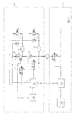
- a tractor comprises a chassis designated generally at 10 and a wheel designated generally at 12. It should be understood that Figure 1 is highly schematic and features located within dashed box 10 are located anywhere on the tractor whereas those features within dashed box 12 are integrated with the wheel and rotate therewith. Furthermore the tractor comprises at least four wheels wherein two or maybe four have the same construction as described below with reference to wheel 12.
- the wheel 12 comprises a generally cylindrical rim (not shown) upon which a tubeless tyre is mounted.
- a toroidal air reservoir 14 formed of reinforced rubber is disposed on the wheel rim within the volume defined by the tyre. Therefore the air reservoir forms an inner chamber 14 of pressurised air and the tyre forms an outer chamber 16.
- the volume of the air reservoir 14 is substantially fixed due to the reinforcement of the rubber material. Therefore deformation of the material between the air reservoir and the tyre volume does not occur when significant pressure differences arise between the chambers 14,16.
- the volume of air reservoir 14 is in the region of 320 litres and the inflatable volume of tyre 16 is in the region of 490 litres.
- the maximum operating pressure of the air reservoir is around 6 bar whereas the operating pressure of the tyre 16 typically varies between 0.8 and 2 bar.
- the system comprises a decant valve 18 and a deflate valve 20 each of which is a pilot controlled check valve.
- Decant valve 18 is located in a fluid transfer line between the air reservoir 14 and tyre 16.
- Deflate valve 20 is located in a fluid transfer line between the tyre 16 and the environment.
- Each check valve 18, 20 has associated therewith a piezoelectric control valve.
- a first piezoelectric valve 22 controls the delivery of a pilot pressure taken from air reservoir 14 to decant valve 18 via pilot line 24.
- a second piezoelectric control valve 26 controls the delivery of a pilot pressure also from air reservoir 14 to the deflate valve 20 via pilot line 28.
- Each piezoelectric valve 22, 26 is activated by a valve control unit 30 employing electrical signals sent via respective lines 31,32.
- decant valve 18 in a closed position in normal operation.
- piezoelectric valve 22 By activation of piezoelectric valve 22 a pilot pressure opens decant valve 18 and allows air to transfer into tyre volume 16 thus increasing the pressure therein.
- Each chamber 14,16 comprises a respective pressure relief valve 34a,34b which can be preset to relieve the pressure within the respective chamber when it exceeds a predetermined value.
- each chamber 14,16 has associated therewith a pressure sensor 35a,35b each with a respective wired link to valve control unit 30.
- Each pressure sensor 35a,35b senses the pressure in the associated volume and transmits this information to the valve control unit 30.
- a rechargeable battery 36 is arranged within the wheel assembly 12 so as to power the valve control unit 30.
- the battery may be replaced with a capacitor which can deliver a high current and be charged over a short period. Apparatus to charge the battery 36 will be described in more detail below.
- the pressure control system further comprises a controller 40 located on the tractor chassis 10.
- the controller 40 is in wireless and bidirectional communication with valve control unit 30 in accordance with the invention by a wireless link.
- the controller 40 is also in communication with a tractor management system 50 which serves to monitor and control various operating parameters of the tractor such as speed, wheel slip and transmission ratio for example.
- An air pressure source 52 is provided by an air pump which is located on the tractor.
- the air source 52 can supply pressurised air via an electric valve 54 and a rotary transfer arrangement 56 and check valve 58 to the reservoir 14.
- the valve 54 is controlled via a wired link by the controller 40.
- the rotary transfer arrangement 56 is of a known construction such as that disclosed in US-6,439,044 by way of example only. This allows pressurised air to be transferred from the chassis 10 to the rotating wheel assembly 12.
- controller 40 which then passes the command to valve control unit 30 via wireless link 42.
- the target pressure is stored locally on the wheel by the valve control unit 30. This value is updated by the controller 40 via the wireless link periodically and/or when a change demand occurs.
- valve control unit 30 activates piezoelectric valve 26 by an electric signal sent by line 32. Piezoelectric valve 26 is activated for a predetermined duration of say 5 seconds which causes deflate valve 20 to open thereby reducing the pressure in tyre 16. The pressure sensed in tyre 16 is then compared to the commanded pressure and, if further deflation is required, piezoelectric valve 26 is activated for another period.
- the duration at which the piezoelectric valves 22,26 are activated may be determined by an algorithm which takes into account the existing pressure in chambers 14,16 and the target pressure of tyre 16.
- real time adjustment may be employed to set the inflation pressure at the desired value by constant measuring of the pressure in combination with control of the decant process.
- valve control unit 30 continually monitors the pressure within tyre 16 and compares it to the target pressure and activate the piezoelectric valves 22,26 accordingly.
- the above described control and monitoring of the inflation pressure is executed on a local basis at the wheel by the valve control unit 30.
- the target pressure By only updating the target pressure when a change is required (either demanded manually by the driver or automatically via the management system 50) the number of messages passing over the wireless link 42 is minimised.
- this reduces the energy consumption of the battery 36 and avoids unreliable control caused by discontinuities in the wireless connection 42.
- control and monitoring of the inflation pressure may be done instead by the controller 40 via wireless link 42 wherein valve control unit 30 simply serves to pass on the sensed parameters and control the valves 22, 26 as demanded.
- the target inflation pressure in this case is stored by the controller 40 or management system 50.
- valve control unit 30 commands a top-up action to controller 40 via wireless link 42. Such a command triggers activation of piezoelectric valve 54 which transfers air under pressure from air source 52 to air reservoir 14 until the target pressure is obtained.
- a generator module is provided to recharge the battery 36 by exploiting the available energy of the pressurised air in the fluid system.
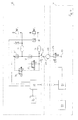
- a turbine 60 is disposed in the air stream of the air which is expelled upon deflation from tyre 16. The turbine 60 powers generator G which serves to recharge battery 36 thereby increasing the lifetime thereof.
- a turbine 62 is located in a dedicate air stream between the reservoir 14 and the environment.
- a check valve 64 regulates the expulsion of air through the turbine 62 and is opened by a pilot pressure sourced from the reservoir 14 and applied via a piezoelectric valve 66 which is in communication with the valve control unit 30.
- the valve control unit 30 can activate valve 66 when the electrical energy in the battery 36 is sensed to be below a predetermined threshold. Therefore generator G can be activated upon demand and does not rely on a deflation step as per the embodiment of Figure 2 .
- a turbine 68 is connected in the air stream between the rotary transfer arrangement 56 and the reservoir 14.
- the turbine 68 powers a generator G which serves to recharge battery 36.
- the turbine 68 is driven each occasion air is transferred from the vehicle air supply 52 to the reservoir 14.
- the charging of the battery can be provided independent from decant/inflate process.
- the presence of the pressure relief valve 34a associated with reservoir 14, allows air to be transferred from the vehicle 10 to the reservoir 14 whenever a charging of the battery 36 is required and without affecting the other parts of the system.
- the turbine may be replaced by a dynamo which is driven by the mechanical rotation of wheel 12.
- a tyre inflation pressure control system comprising a vehicle wheel having a rim with a tyre mounted thereon and an air reservoir.
- the system further comprises a decant valve for allowing air to transfer from the reservoir into the tyre and a deflate valve for deflating the tyre.
- a valve control unit fixed relative to the wheel is in communication with a controller which is fixed relative to the vehicle.
Landscapes
- Engineering & Computer Science (AREA)
- Mechanical Engineering (AREA)
- Vehicle Cleaning, Maintenance, Repair, Refitting, And Outriggers (AREA)
- Measuring Fluid Pressure (AREA)
Applications Claiming Priority (1)
| Application Number | Priority Date | Filing Date | Title |
|---|---|---|---|
| GB0822561A GB2466203A (en) | 2008-12-11 | 2008-12-11 | Tyre inflation pressure control system |
Publications (3)
| Publication Number | Publication Date |
|---|---|
| EP2196336A2 true EP2196336A2 (de) | 2010-06-16 |
| EP2196336A3 EP2196336A3 (de) | 2010-12-29 |
| EP2196336B1 EP2196336B1 (de) | 2012-10-03 |
Family
ID=40289837
Family Applications (1)
| Application Number | Title | Priority Date | Filing Date |
|---|---|---|---|
| EP09178383A Not-in-force EP2196336B1 (de) | 2008-12-11 | 2009-12-08 | Drucksteuerungssystem zum Aufpumpen von Reifen |
Country Status (2)
| Country | Link |
|---|---|
| EP (1) | EP2196336B1 (de) |
| GB (1) | GB2466203A (de) |
Cited By (6)
| Publication number | Priority date | Publication date | Assignee | Title |
|---|---|---|---|---|
| EP3127721A1 (de) | 2015-08-03 | 2017-02-08 | AGCO International GmbH | Regenerierung eines lufttrockners an einem fahrzeug |
| WO2019147766A1 (en) * | 2018-01-25 | 2019-08-01 | Parker Hannifin Corporation | Inflation/deflation system |
| CN110509727A (zh) * | 2018-05-22 | 2019-11-29 | 烟台汽车工程职业学院 | 一种自动调节附着系数的轮胎控制系统 |
| US10953706B2 (en) | 2015-12-29 | 2021-03-23 | Bridgestone Americas Tire Operations, Llc | Air storage system for rapid tire inflation |
| US10953707B2 (en) | 2015-12-29 | 2021-03-23 | Bridgestone Americas Tire Operations, Llc | Air distribution system for rapid tire inflation |
| US11021023B2 (en) | 2015-12-29 | 2021-06-01 | Bridgestone Americas Tire Operations, Llc | Rapid tire inflation system with air compressor |
Families Citing this family (5)
| Publication number | Priority date | Publication date | Assignee | Title |
|---|---|---|---|---|
| DE102014109358A1 (de) | 2014-07-04 | 2016-01-07 | Dr. Ing. H.C. F. Porsche Aktiengesellschaft | Kraftfahrzeug mit einer Reifenmess- und befüllvorrichtung |
| ES2568153B1 (es) * | 2014-10-27 | 2017-02-07 | Jan Georges Annie FRAMMONT MUYLLE | Sistema automático de regulación de presión con control remoto |
| GB201720747D0 (en) | 2017-12-13 | 2018-01-24 | Agco Int Gmbh | Tyre inflation pressure control system |
| GB201720751D0 (en) | 2017-12-13 | 2018-01-24 | Agco Int Gmbh | Dual wheel tyre inflation pressure control system |
| IL313435B2 (en) * | 2024-06-06 | 2025-01-01 | Peri Idan | Tire valve with secondary air release mechanism |
Family Cites Families (7)
| Publication number | Priority date | Publication date | Assignee | Title |
|---|---|---|---|---|
| US3934223A (en) * | 1973-12-04 | 1976-01-20 | Safety Research & Engineering Corporation | Tire pressure warning system |
| US4582108A (en) * | 1984-07-26 | 1986-04-15 | Grumman Aerospace Corporation | Tire inflation/deflation system |
| US5452753A (en) * | 1993-04-22 | 1995-09-26 | Hughes Aircraft Company | Vehicle tire management system including wheel with self-contained tire inflation/deflation apparatus |
| US6601625B2 (en) * | 2000-11-22 | 2003-08-05 | Richard M. Rheinhardt | Wheel with integral compressed air tank apparatus |
| EP1417106B1 (de) * | 2001-08-14 | 2005-03-02 | Steyr-Daimler-Puch Spezialfahrzeug AG & Co. KG | Verfahren und vorrichtung zum betreiben einer einrichtung zum überwachen und drahtlosen signalisieren einer druckänderung und zur automatischen druckregelung in luftreifen an fahrzeugen |
| FR2834671B1 (fr) * | 2002-01-11 | 2005-03-25 | Labinal | Ensemble a roue gonflable |
| US20060201598A1 (en) * | 2005-03-08 | 2006-09-14 | Rheinhardt Richard D | Tire inflation maintenance apparatus |
-
2008
- 2008-12-11 GB GB0822561A patent/GB2466203A/en not_active Withdrawn
-
2009
- 2009-12-08 EP EP09178383A patent/EP2196336B1/de not_active Not-in-force
Cited By (8)
| Publication number | Priority date | Publication date | Assignee | Title |
|---|---|---|---|---|
| EP3127721A1 (de) | 2015-08-03 | 2017-02-08 | AGCO International GmbH | Regenerierung eines lufttrockners an einem fahrzeug |
| US10953706B2 (en) | 2015-12-29 | 2021-03-23 | Bridgestone Americas Tire Operations, Llc | Air storage system for rapid tire inflation |
| US10953707B2 (en) | 2015-12-29 | 2021-03-23 | Bridgestone Americas Tire Operations, Llc | Air distribution system for rapid tire inflation |
| US11021023B2 (en) | 2015-12-29 | 2021-06-01 | Bridgestone Americas Tire Operations, Llc | Rapid tire inflation system with air compressor |
| WO2019147766A1 (en) * | 2018-01-25 | 2019-08-01 | Parker Hannifin Corporation | Inflation/deflation system |
| US11787239B2 (en) | 2018-01-25 | 2023-10-17 | Parker-Hannifin Corporation | Inflation/deflation system |
| CN110509727A (zh) * | 2018-05-22 | 2019-11-29 | 烟台汽车工程职业学院 | 一种自动调节附着系数的轮胎控制系统 |
| CN110509727B (zh) * | 2018-05-22 | 2024-02-13 | 烟台汽车工程职业学院 | 一种自动调节附着系数的轮胎控制系统 |
Also Published As
| Publication number | Publication date |
|---|---|
| GB0822561D0 (en) | 2009-01-14 |
| EP2196336A3 (de) | 2010-12-29 |
| EP2196336B1 (de) | 2012-10-03 |
| GB2466203A (en) | 2010-06-16 |
Similar Documents
| Publication | Publication Date | Title |
|---|---|---|
| EP2196336B1 (de) | Drucksteuerungssystem zum Aufpumpen von Reifen | |
| US6744356B2 (en) | Tire pressure maintenance and monitoring system | |
| US6994136B2 (en) | Wheel end tire air pump | |
| CN105939873B (zh) | 轮胎装置 | |
| CN105270108B (zh) | 用于提供与胎压有关的信息的胎压传感器模块、胎压监测系统、车轮、方法和计算机程序 | |
| US8562023B2 (en) | Vehicle with pneumatic tire and method for cooling tire in the vehicle | |
| JP6896648B2 (ja) | 車両の負荷を見積もる方法 | |
| US6212464B1 (en) | Slip control using an automatic central tire inflation system | |
| CN110831786A (zh) | 用于重型车辆的基于负荷的轮胎充气系统 | |
| US20200130437A1 (en) | Apparatus and method for automatic tire inflation system | |
| KR20190118951A (ko) | 타이어 압력 제어 시스템 및 구성요소들 | |
| JPH05238216A (ja) | 中央タイヤ空気圧制御装置およびその空気圧を制御する方法 | |
| US20220144016A1 (en) | Fuel efficiency system for a vehicle | |
| US6976391B2 (en) | System for regulating tire inflation pressure | |
| EP2994323A2 (de) | Umfassendes reifendruckwartungssystem | |
| EP3397532A1 (de) | Schnelles reifenaufblassystem mit luftkompressor | |
| WO1998001310A1 (en) | Device for automatic maintenance of correct tyre pressure | |
| EP3743297B1 (de) | Inflations-/deflationssystem | |
| CN106687307A (zh) | 尤其用于商用车挂车的机械式驱动的轮胎压力调节设备 | |
| JP7337814B2 (ja) | 制御圧力及び/又は作動圧力をホイールハブ又はホイールハブに支持された車両用ホイールに伝達する回転型伝達装置 | |
| KR101879118B1 (ko) | 공기입 타이어의 공기압제어 장치 | |
| WO2011007006A1 (en) | Vehicle battery charging apparatus | |
| KR100423040B1 (ko) | 차량 타이어 공기압 보충장치 | |
| TR2025023422A2 (tr) | Yol koşullarina göre uyarlanabi̇li̇r akilli lasti̇k si̇stem | |
| MX2007009951A (es) | Rueda neumatica con capacidad de dos fases de presion de aire. |
Legal Events
| Date | Code | Title | Description |
|---|---|---|---|
| PUAI | Public reference made under article 153(3) epc to a published international application that has entered the european phase |
Free format text: ORIGINAL CODE: 0009012 |
|
| AK | Designated contracting states |
Kind code of ref document: A2 Designated state(s): AT BE BG CH CY CZ DE DK EE ES FI FR GB GR HR HU IE IS IT LI LT LU LV MC MK MT NL NO PL PT RO SE SI SK SM TR |
|
| AX | Request for extension of the european patent |
Extension state: AL BA RS |
|
| PUAL | Search report despatched |
Free format text: ORIGINAL CODE: 0009013 |
|
| AK | Designated contracting states |
Kind code of ref document: A3 Designated state(s): AT BE BG CH CY CZ DE DK EE ES FI FR GB GR HR HU IE IS IT LI LT LU LV MC MK MT NL NO PL PT RO SE SI SK SM TR |
|
| AX | Request for extension of the european patent |
Extension state: AL BA RS |
|
| 17P | Request for examination filed |
Effective date: 20110914 |
|
| GRAP | Despatch of communication of intention to grant a patent |
Free format text: ORIGINAL CODE: EPIDOSNIGR1 |
|
| GRAS | Grant fee paid |
Free format text: ORIGINAL CODE: EPIDOSNIGR3 |
|
| GRAA | (expected) grant |
Free format text: ORIGINAL CODE: 0009210 |
|
| AK | Designated contracting states |
Kind code of ref document: B1 Designated state(s): AT BE BG CH CY CZ DE DK EE ES FI FR GB GR HR HU IE IS IT LI LT LU LV MC MK MT NL NO PL PT RO SE SI SK SM TR |
|
| REG | Reference to a national code |
Ref country code: GB Ref legal event code: FG4D |
|
| REG | Reference to a national code |
Ref country code: AT Ref legal event code: REF Ref document number: 577801 Country of ref document: AT Kind code of ref document: T Effective date: 20121015 Ref country code: CH Ref legal event code: EP |
|
| REG | Reference to a national code |
Ref country code: IE Ref legal event code: FG4D |
|
| REG | Reference to a national code |
Ref country code: DE Ref legal event code: R096 Ref document number: 602009010145 Country of ref document: DE Effective date: 20121129 |
|
| REG | Reference to a national code |
Ref country code: AT Ref legal event code: MK05 Ref document number: 577801 Country of ref document: AT Kind code of ref document: T Effective date: 20121003 |
|
| PG25 | Lapsed in a contracting state [announced via postgrant information from national office to epo] |
Ref country code: SI Free format text: LAPSE BECAUSE OF FAILURE TO SUBMIT A TRANSLATION OF THE DESCRIPTION OR TO PAY THE FEE WITHIN THE PRESCRIBED TIME-LIMIT Effective date: 20121003 |
|
| REG | Reference to a national code |
Ref country code: NL Ref legal event code: VDEP Effective date: 20121003 |
|
| REG | Reference to a national code |
Ref country code: LT Ref legal event code: MG4D |
|
| PG25 | Lapsed in a contracting state [announced via postgrant information from national office to epo] |
Ref country code: NO Free format text: LAPSE BECAUSE OF FAILURE TO SUBMIT A TRANSLATION OF THE DESCRIPTION OR TO PAY THE FEE WITHIN THE PRESCRIBED TIME-LIMIT Effective date: 20130103 Ref country code: IS Free format text: LAPSE BECAUSE OF FAILURE TO SUBMIT A TRANSLATION OF THE DESCRIPTION OR TO PAY THE FEE WITHIN THE PRESCRIBED TIME-LIMIT Effective date: 20130203 Ref country code: HR Free format text: LAPSE BECAUSE OF FAILURE TO SUBMIT A TRANSLATION OF THE DESCRIPTION OR TO PAY THE FEE WITHIN THE PRESCRIBED TIME-LIMIT Effective date: 20121003 Ref country code: NL Free format text: LAPSE BECAUSE OF FAILURE TO SUBMIT A TRANSLATION OF THE DESCRIPTION OR TO PAY THE FEE WITHIN THE PRESCRIBED TIME-LIMIT Effective date: 20121003 Ref country code: SE Free format text: LAPSE BECAUSE OF FAILURE TO SUBMIT A TRANSLATION OF THE DESCRIPTION OR TO PAY THE FEE WITHIN THE PRESCRIBED TIME-LIMIT Effective date: 20121003 Ref country code: ES Free format text: LAPSE BECAUSE OF FAILURE TO SUBMIT A TRANSLATION OF THE DESCRIPTION OR TO PAY THE FEE WITHIN THE PRESCRIBED TIME-LIMIT Effective date: 20130114 Ref country code: LT Free format text: LAPSE BECAUSE OF FAILURE TO SUBMIT A TRANSLATION OF THE DESCRIPTION OR TO PAY THE FEE WITHIN THE PRESCRIBED TIME-LIMIT Effective date: 20121003 Ref country code: FI Free format text: LAPSE BECAUSE OF FAILURE TO SUBMIT A TRANSLATION OF THE DESCRIPTION OR TO PAY THE FEE WITHIN THE PRESCRIBED TIME-LIMIT Effective date: 20121003 |
|
| PG25 | Lapsed in a contracting state [announced via postgrant information from national office to epo] |
Ref country code: GR Free format text: LAPSE BECAUSE OF FAILURE TO SUBMIT A TRANSLATION OF THE DESCRIPTION OR TO PAY THE FEE WITHIN THE PRESCRIBED TIME-LIMIT Effective date: 20130104 Ref country code: LV Free format text: LAPSE BECAUSE OF FAILURE TO SUBMIT A TRANSLATION OF THE DESCRIPTION OR TO PAY THE FEE WITHIN THE PRESCRIBED TIME-LIMIT Effective date: 20121003 Ref country code: BE Free format text: LAPSE BECAUSE OF FAILURE TO SUBMIT A TRANSLATION OF THE DESCRIPTION OR TO PAY THE FEE WITHIN THE PRESCRIBED TIME-LIMIT Effective date: 20121003 Ref country code: PL Free format text: LAPSE BECAUSE OF FAILURE TO SUBMIT A TRANSLATION OF THE DESCRIPTION OR TO PAY THE FEE WITHIN THE PRESCRIBED TIME-LIMIT Effective date: 20121003 Ref country code: PT Free format text: LAPSE BECAUSE OF FAILURE TO SUBMIT A TRANSLATION OF THE DESCRIPTION OR TO PAY THE FEE WITHIN THE PRESCRIBED TIME-LIMIT Effective date: 20130204 |
|
| PG25 | Lapsed in a contracting state [announced via postgrant information from national office to epo] |
Ref country code: AT Free format text: LAPSE BECAUSE OF FAILURE TO SUBMIT A TRANSLATION OF THE DESCRIPTION OR TO PAY THE FEE WITHIN THE PRESCRIBED TIME-LIMIT Effective date: 20121003 |
|
| PG25 | Lapsed in a contracting state [announced via postgrant information from national office to epo] |
Ref country code: MC Free format text: LAPSE BECAUSE OF NON-PAYMENT OF DUE FEES Effective date: 20121231 Ref country code: CZ Free format text: LAPSE BECAUSE OF FAILURE TO SUBMIT A TRANSLATION OF THE DESCRIPTION OR TO PAY THE FEE WITHIN THE PRESCRIBED TIME-LIMIT Effective date: 20121003 Ref country code: SK Free format text: LAPSE BECAUSE OF FAILURE TO SUBMIT A TRANSLATION OF THE DESCRIPTION OR TO PAY THE FEE WITHIN THE PRESCRIBED TIME-LIMIT Effective date: 20121003 Ref country code: BG Free format text: LAPSE BECAUSE OF FAILURE TO SUBMIT A TRANSLATION OF THE DESCRIPTION OR TO PAY THE FEE WITHIN THE PRESCRIBED TIME-LIMIT Effective date: 20130103 Ref country code: DK Free format text: LAPSE BECAUSE OF FAILURE TO SUBMIT A TRANSLATION OF THE DESCRIPTION OR TO PAY THE FEE WITHIN THE PRESCRIBED TIME-LIMIT Effective date: 20121003 Ref country code: EE Free format text: LAPSE BECAUSE OF FAILURE TO SUBMIT A TRANSLATION OF THE DESCRIPTION OR TO PAY THE FEE WITHIN THE PRESCRIBED TIME-LIMIT Effective date: 20121003 |
|
| PLBE | No opposition filed within time limit |
Free format text: ORIGINAL CODE: 0009261 |
|
| STAA | Information on the status of an ep patent application or granted ep patent |
Free format text: STATUS: NO OPPOSITION FILED WITHIN TIME LIMIT |
|
| PG25 | Lapsed in a contracting state [announced via postgrant information from national office to epo] |
Ref country code: RO Free format text: LAPSE BECAUSE OF FAILURE TO SUBMIT A TRANSLATION OF THE DESCRIPTION OR TO PAY THE FEE WITHIN THE PRESCRIBED TIME-LIMIT Effective date: 20121003 |
|
| 26N | No opposition filed |
Effective date: 20130704 |
|
| REG | Reference to a national code |
Ref country code: IE Ref legal event code: MM4A |
|
| PG25 | Lapsed in a contracting state [announced via postgrant information from national office to epo] |
Ref country code: IE Free format text: LAPSE BECAUSE OF NON-PAYMENT OF DUE FEES Effective date: 20121208 |
|
| REG | Reference to a national code |
Ref country code: DE Ref legal event code: R097 Ref document number: 602009010145 Country of ref document: DE Effective date: 20130704 |
|
| PG25 | Lapsed in a contracting state [announced via postgrant information from national office to epo] |
Ref country code: CY Free format text: LAPSE BECAUSE OF FAILURE TO SUBMIT A TRANSLATION OF THE DESCRIPTION OR TO PAY THE FEE WITHIN THE PRESCRIBED TIME-LIMIT Effective date: 20121003 Ref country code: MT Free format text: LAPSE BECAUSE OF FAILURE TO SUBMIT A TRANSLATION OF THE DESCRIPTION OR TO PAY THE FEE WITHIN THE PRESCRIBED TIME-LIMIT Effective date: 20121003 |
|
| PG25 | Lapsed in a contracting state [announced via postgrant information from national office to epo] |
Ref country code: TR Free format text: LAPSE BECAUSE OF FAILURE TO SUBMIT A TRANSLATION OF THE DESCRIPTION OR TO PAY THE FEE WITHIN THE PRESCRIBED TIME-LIMIT Effective date: 20121003 |
|
| PG25 | Lapsed in a contracting state [announced via postgrant information from national office to epo] |
Ref country code: LU Free format text: LAPSE BECAUSE OF NON-PAYMENT OF DUE FEES Effective date: 20121208 Ref country code: SM Free format text: LAPSE BECAUSE OF FAILURE TO SUBMIT A TRANSLATION OF THE DESCRIPTION OR TO PAY THE FEE WITHIN THE PRESCRIBED TIME-LIMIT Effective date: 20121003 |
|
| PG25 | Lapsed in a contracting state [announced via postgrant information from national office to epo] |
Ref country code: HU Free format text: LAPSE BECAUSE OF FAILURE TO SUBMIT A TRANSLATION OF THE DESCRIPTION OR TO PAY THE FEE WITHIN THE PRESCRIBED TIME-LIMIT Effective date: 20091208 |
|
| REG | Reference to a national code |
Ref country code: CH Ref legal event code: PL |
|
| PG25 | Lapsed in a contracting state [announced via postgrant information from national office to epo] |
Ref country code: CH Free format text: LAPSE BECAUSE OF NON-PAYMENT OF DUE FEES Effective date: 20131231 Ref country code: LI Free format text: LAPSE BECAUSE OF NON-PAYMENT OF DUE FEES Effective date: 20131231 |
|
| PG25 | Lapsed in a contracting state [announced via postgrant information from national office to epo] |
Ref country code: MK Free format text: LAPSE BECAUSE OF FAILURE TO SUBMIT A TRANSLATION OF THE DESCRIPTION OR TO PAY THE FEE WITHIN THE PRESCRIBED TIME-LIMIT Effective date: 20121003 |
|
| REG | Reference to a national code |
Ref country code: FR Ref legal event code: PLFP Year of fee payment: 7 |
|
| REG | Reference to a national code |
Ref country code: FR Ref legal event code: PLFP Year of fee payment: 8 |
|
| REG | Reference to a national code |
Ref country code: FR Ref legal event code: PLFP Year of fee payment: 9 |
|
| PGFP | Annual fee paid to national office [announced via postgrant information from national office to epo] |
Ref country code: GB Payment date: 20221223 Year of fee payment: 14 Ref country code: FR Payment date: 20221222 Year of fee payment: 14 Ref country code: DE Payment date: 20220620 Year of fee payment: 14 |
|
| PGFP | Annual fee paid to national office [announced via postgrant information from national office to epo] |
Ref country code: IT Payment date: 20221227 Year of fee payment: 14 |
|
| P01 | Opt-out of the competence of the unified patent court (upc) registered |
Effective date: 20230518 |
|
| REG | Reference to a national code |
Ref country code: DE Ref legal event code: R119 Ref document number: 602009010145 Country of ref document: DE |
|
| GBPC | Gb: european patent ceased through non-payment of renewal fee |
Effective date: 20231208 |
|
| PG25 | Lapsed in a contracting state [announced via postgrant information from national office to epo] |
Ref country code: DE Free format text: LAPSE BECAUSE OF NON-PAYMENT OF DUE FEES Effective date: 20240702 |
|
| PG25 | Lapsed in a contracting state [announced via postgrant information from national office to epo] |
Ref country code: GB Free format text: LAPSE BECAUSE OF NON-PAYMENT OF DUE FEES Effective date: 20231208 |
|
| PG25 | Lapsed in a contracting state [announced via postgrant information from national office to epo] |
Ref country code: FR Free format text: LAPSE BECAUSE OF NON-PAYMENT OF DUE FEES Effective date: 20231231 |
|
| PG25 | Lapsed in a contracting state [announced via postgrant information from national office to epo] |
Ref country code: GB Free format text: LAPSE BECAUSE OF NON-PAYMENT OF DUE FEES Effective date: 20231208 Ref country code: FR Free format text: LAPSE BECAUSE OF NON-PAYMENT OF DUE FEES Effective date: 20231231 Ref country code: DE Free format text: LAPSE BECAUSE OF NON-PAYMENT OF DUE FEES Effective date: 20240702 |
|
| PG25 | Lapsed in a contracting state [announced via postgrant information from national office to epo] |
Ref country code: IT Free format text: LAPSE BECAUSE OF NON-PAYMENT OF DUE FEES Effective date: 20231208 |