EP2196309B1 - Leading edge for aircraft wings and empennages - Google Patents
Leading edge for aircraft wings and empennages Download PDFInfo
- Publication number
- EP2196309B1 EP2196309B1 EP09177579A EP09177579A EP2196309B1 EP 2196309 B1 EP2196309 B1 EP 2196309B1 EP 09177579 A EP09177579 A EP 09177579A EP 09177579 A EP09177579 A EP 09177579A EP 2196309 B1 EP2196309 B1 EP 2196309B1
- Authority
- EP
- European Patent Office
- Prior art keywords
- layer
- leading edge
- edge structure
- structure according
- panel
- Prior art date
- Legal status (The legal status is an assumption and is not a legal conclusion. Google has not performed a legal analysis and makes no representation as to the accuracy of the status listed.)
- Active
Links
- 229910052751 metal Inorganic materials 0.000 claims abstract description 22
- 239000002184 metal Substances 0.000 claims abstract description 22
- 239000011152 fibreglass Substances 0.000 claims abstract description 12
- 239000011888 foil Substances 0.000 claims abstract description 11
- 239000000853 adhesive Substances 0.000 claims description 8
- 229910052782 aluminium Inorganic materials 0.000 claims description 8
- XAGFODPZIPBFFR-UHFFFAOYSA-N aluminium Chemical compound [Al] XAGFODPZIPBFFR-UHFFFAOYSA-N 0.000 claims description 8
- 230000001070 adhesive effect Effects 0.000 claims description 7
- 239000004411 aluminium Substances 0.000 claims description 6
- 239000000956 alloy Substances 0.000 claims description 4
- 229910045601 alloy Inorganic materials 0.000 claims description 4
- 241000264877 Hippospongia communis Species 0.000 claims 6
- 230000001419 dependent effect Effects 0.000 claims 2
- 239000010410 layer Substances 0.000 description 26
- 239000005030 aluminium foil Substances 0.000 description 7
- 230000000694 effects Effects 0.000 description 2
- 230000004313 glare Effects 0.000 description 2
- 239000000463 material Substances 0.000 description 2
- 239000004033 plastic Substances 0.000 description 2
- 229910000838 Al alloy Inorganic materials 0.000 description 1
- RTAQQCXQSZGOHL-UHFFFAOYSA-N Titanium Chemical compound [Ti] RTAQQCXQSZGOHL-UHFFFAOYSA-N 0.000 description 1
- 239000002313 adhesive film Substances 0.000 description 1
- 238000010276 construction Methods 0.000 description 1
- 230000008878 coupling Effects 0.000 description 1
- 238000010168 coupling process Methods 0.000 description 1
- 238000005859 coupling reaction Methods 0.000 description 1
- 238000005516 engineering process Methods 0.000 description 1
- 150000002739 metals Chemical class 0.000 description 1
- 238000012986 modification Methods 0.000 description 1
- 230000004048 modification Effects 0.000 description 1
- 230000002093 peripheral effect Effects 0.000 description 1
- 230000001105 regulatory effect Effects 0.000 description 1
- 238000007789 sealing Methods 0.000 description 1
- 239000002356 single layer Substances 0.000 description 1
- 239000010936 titanium Substances 0.000 description 1
- 229910052719 titanium Inorganic materials 0.000 description 1
Images

Classifications
-
- B—PERFORMING OPERATIONS; TRANSPORTING
- B64—AIRCRAFT; AVIATION; COSMONAUTICS
- B64C—AEROPLANES; HELICOPTERS
- B64C3/00—Wings
- B64C3/28—Leading or trailing edges attached to primary structures, e.g. forming fixed slots
-
- B—PERFORMING OPERATIONS; TRANSPORTING
- B32—LAYERED PRODUCTS
- B32B—LAYERED PRODUCTS, i.e. PRODUCTS BUILT-UP OF STRATA OF FLAT OR NON-FLAT, e.g. CELLULAR OR HONEYCOMB, FORM
- B32B15/00—Layered products comprising a layer of metal
- B32B15/14—Layered products comprising a layer of metal next to a fibrous or filamentary layer
-
- B—PERFORMING OPERATIONS; TRANSPORTING
- B32—LAYERED PRODUCTS
- B32B—LAYERED PRODUCTS, i.e. PRODUCTS BUILT-UP OF STRATA OF FLAT OR NON-FLAT, e.g. CELLULAR OR HONEYCOMB, FORM
- B32B15/00—Layered products comprising a layer of metal
- B32B15/20—Layered products comprising a layer of metal comprising aluminium or copper
-
- B—PERFORMING OPERATIONS; TRANSPORTING
- B32—LAYERED PRODUCTS
- B32B—LAYERED PRODUCTS, i.e. PRODUCTS BUILT-UP OF STRATA OF FLAT OR NON-FLAT, e.g. CELLULAR OR HONEYCOMB, FORM
- B32B3/00—Layered products comprising a layer with external or internal discontinuities or unevennesses, or a layer of non-planar shape; Layered products comprising a layer having particular features of form
- B32B3/02—Layered products comprising a layer with external or internal discontinuities or unevennesses, or a layer of non-planar shape; Layered products comprising a layer having particular features of form characterised by features of form at particular places, e.g. in edge regions
-
- B—PERFORMING OPERATIONS; TRANSPORTING
- B32—LAYERED PRODUCTS
- B32B—LAYERED PRODUCTS, i.e. PRODUCTS BUILT-UP OF STRATA OF FLAT OR NON-FLAT, e.g. CELLULAR OR HONEYCOMB, FORM
- B32B3/00—Layered products comprising a layer with external or internal discontinuities or unevennesses, or a layer of non-planar shape; Layered products comprising a layer having particular features of form
- B32B3/10—Layered products comprising a layer with external or internal discontinuities or unevennesses, or a layer of non-planar shape; Layered products comprising a layer having particular features of form characterised by a discontinuous layer, i.e. formed of separate pieces of material
- B32B3/12—Layered products comprising a layer with external or internal discontinuities or unevennesses, or a layer of non-planar shape; Layered products comprising a layer having particular features of form characterised by a discontinuous layer, i.e. formed of separate pieces of material characterised by a layer of regularly- arranged cells, e.g. a honeycomb structure
-
- B—PERFORMING OPERATIONS; TRANSPORTING
- B32—LAYERED PRODUCTS
- B32B—LAYERED PRODUCTS, i.e. PRODUCTS BUILT-UP OF STRATA OF FLAT OR NON-FLAT, e.g. CELLULAR OR HONEYCOMB, FORM
- B32B7/00—Layered products characterised by the relation between layers; Layered products characterised by the relative orientation of features between layers, or by the relative values of a measurable parameter between layers, i.e. products comprising layers having different physical, chemical or physicochemical properties; Layered products characterised by the interconnection of layers
- B32B7/04—Interconnection of layers
- B32B7/12—Interconnection of layers using interposed adhesives or interposed materials with bonding properties
-
- B—PERFORMING OPERATIONS; TRANSPORTING
- B32—LAYERED PRODUCTS
- B32B—LAYERED PRODUCTS, i.e. PRODUCTS BUILT-UP OF STRATA OF FLAT OR NON-FLAT, e.g. CELLULAR OR HONEYCOMB, FORM
- B32B2250/00—Layers arrangement
- B32B2250/04—4 layers
-
- B—PERFORMING OPERATIONS; TRANSPORTING
- B32—LAYERED PRODUCTS
- B32B—LAYERED PRODUCTS, i.e. PRODUCTS BUILT-UP OF STRATA OF FLAT OR NON-FLAT, e.g. CELLULAR OR HONEYCOMB, FORM
- B32B2262/00—Composition or structural features of fibres which form a fibrous or filamentary layer or are present as additives
- B32B2262/10—Inorganic fibres
- B32B2262/101—Glass fibres
-
- B—PERFORMING OPERATIONS; TRANSPORTING
- B32—LAYERED PRODUCTS
- B32B—LAYERED PRODUCTS, i.e. PRODUCTS BUILT-UP OF STRATA OF FLAT OR NON-FLAT, e.g. CELLULAR OR HONEYCOMB, FORM
- B32B2605/00—Vehicles
- B32B2605/18—Aircraft
-
- Y—GENERAL TAGGING OF NEW TECHNOLOGICAL DEVELOPMENTS; GENERAL TAGGING OF CROSS-SECTIONAL TECHNOLOGIES SPANNING OVER SEVERAL SECTIONS OF THE IPC; TECHNICAL SUBJECTS COVERED BY FORMER USPC CROSS-REFERENCE ART COLLECTIONS [XRACs] AND DIGESTS
- Y10—TECHNICAL SUBJECTS COVERED BY FORMER USPC
- Y10T—TECHNICAL SUBJECTS COVERED BY FORMER US CLASSIFICATION
- Y10T428/00—Stock material or miscellaneous articles
- Y10T428/24—Structurally defined web or sheet [e.g., overall dimension, etc.]
- Y10T428/24149—Honeycomb-like
Definitions
- the present invention refers to a leading edge structure for aircraft wings and empennages.
- Wings and empennages are primary structures sized in a way such as to have a rigidity and robustness suitable for the aerodynamic loads to which it can be subjected during flight, landing and takeoff.
- the leading edge structure of a wing and of an empennage must also be sized so as to withstand the impact with a flying object.
- the so called "bird strike” test is regulated by FAR 25.631 which states that: if an aircraft suffers an impact with a bird, having a defined weight and at a predetermined speed, after such condition there must be no damage on the primary structures that could prevent the aircraft from safely landing at the nearest available airport. Since whilst flying in cruise conditions the first structural element which can potentially undergo such types of impact is the leading edge, this structure must fully comply with the aforementioned standard. In addition to the aforementioned requirement, it is necessary for the leading edge to be suitably sized so as to withstand aerodynamic loads applied to it.
- the aforementioned structures are commonly designed and manufactured in a manner such as to prevent the leading edge from being pierced, and thus to avoid possible damage to the structure behind it, or, in the case in which piercing is foreseen, they are designed so that the damage is locally limited.
- wing structures are made from aluminium (shell thicknesses generally of only a few millimetres) reinforced by transverse elements which have the main task of giving the profile its shape.
- the task of absorbing energy is carried out, apart from by the - generally curved - shape of the leading edge, it is especially carried out by its thickness. The greater the thickness, the higher the amount of energy absorbed.
- wing structures use hybrid material such as Glare@ (fibreglass and aluminium laminate) also for the leading edge.
- the energy is absorbed as well as by the curved shape of the leading edge, particularly by the coupling between fibre-glass and aluminium.
- Fibre-glass contributes in an important way to absorbing a substantial fraction of the elasto-plastic deformation energy due to impact; this effect is called "bridging" in the field of the materials applied to aircrafts.
- the present invention has the purpose of making an improved structure for the leading edge of a wing or of an empennage, mainly tackling the problem of optimizing the rigidity of the structure, minimizing the damage caused by impact with flying objects and at the same time reducing the overall weight of the wing or of the empennage.
- a leading edge structure of a wing or of an empennage is wholly indicated with reference numeral 10.
- the term “front” refers to the forward direction of the aircraft, whereas the terms “outer” and “inner” generally refer to a condition in which the leading edge structure is assembled to the rest of the wing or of the empennage, so that the "inner” elements are enclosed in the inner wing or empennage structure.
- the leading edge structure 10 constitutes the front portion of a wing profile.
- the structure 10 is formed by an overlapping of a plurality of multilayer panels 20 suitably curved with concavities facing towards a direction defined as "rear" with respect to the forward direction of an aircraft.
- Each multilayer panel has at least the following layers:
- the intermediate layer of fibreglass 22 is connected to the adjacent layers through respective structural adhesive film layers 25.
- a self-adhesive fibreglass can be chosen.
- each multilayer panel 20 comprises a fourth layer 24 consisting of a last aluminium foil which is fixed to the third layer 23 of the same panel by means of adhesives. The two panels are then fixed to one another through an adhesive 25 applied between the fourth aluminium foil layer 24 of a panel and the first aluminium foil layer of an adjacent panel.
- Z-shaped fibreglass closing cross pieces are indicated with reference numeral 12, said cross pieces being suitable for sealing the peripheral edges of the multilayer panels 20. It is preferable to choose multilayer panels of the type having a further aluminium foil 24 for the innermost panels, so as to uninterruptedly cover the honeycomb layers 23 of the panels located in this position.
- the aluminium foils are fundamentally used as elements for fastening the fibreglass layers.
- the structural characteristics of high mechanical resistance and resilience of fibreglass, intimately and securely fixed together with the metal honeycomb and with the aluminium foil, provide a bridging effect which contributes to absorbing a substantial fraction of the elasto-plastic energy of deformation caused by impact.
- the invention exploits the ability of the metal honeycomb layer for absorbing another large amount of energy caused by impact. Indeed, the honeycomb layer crushes only in the area in which the impact occurs. Therefore, the damage does not propagate to other parts of the wing or of the empennage.
- the honeycomb layer mainly has a structural function, since it determines the overall rigidity of the leading edge with the advantage of significantly reducing the overall weight of the wing with respect to conventional structures.
- the honeycomb layers illustrated, as an example, in figures 5 and 6 having slightly undulated walls and available on the market under the names Flex-Core® and Double-Flex®, are ideally meant for following single curvature profiles, double slight curvature profiles ( figure 6 ) or double high curvature profiles ( figure 5 ).
- a wing structure constructed according to the present invention allows weight to be saved, having equal overall deformation of the leading edge at the impact zone, of the order of 30% with respect to a structure having comparable rigidity constructed with Glare® technology.
- the invention is not limited to the embodiments described and illustrated hereby, said embodiments should be considered example embodiments of the leading edge; the invention can, however, undergo modifications relative to its shape, size, and the arrangement of its constructive details, as defined by the appended claims.
- the order of the single layers forming the panels can be inverted with respect to what has been illustrated in the present examples, by arranging the first metal foil layer 21 further inside, and the third honeycomb layer (or the fourth metal foil layer 24, if it is foreseen) further outside with respect to the wing or empennage structure.
Landscapes
- Engineering & Computer Science (AREA)
- Mechanical Engineering (AREA)
- Aviation & Aerospace Engineering (AREA)
- Laminated Bodies (AREA)
- Transition And Organic Metals Composition Catalysts For Addition Polymerization (AREA)
- Window Of Vehicle (AREA)
- Confectionery (AREA)
- Vibration Dampers (AREA)
Abstract
Description
- The present invention refers to a leading edge structure for aircraft wings and empennages.
- Wings and empennages (vertical and horizontal) are primary structures sized in a way such as to have a rigidity and robustness suitable for the aerodynamic loads to which it can be subjected during flight, landing and takeoff. The leading edge structure of a wing and of an empennage must also be sized so as to withstand the impact with a flying object.
- The so called "bird strike" test is regulated by FAR 25.631 which states that: if an aircraft suffers an impact with a bird, having a defined weight and at a predetermined speed, after such condition there must be no damage on the primary structures that could prevent the aircraft from safely landing at the nearest available airport. Since whilst flying in cruise conditions the first structural element which can potentially undergo such types of impact is the leading edge, this structure must fully comply with the aforementioned standard. In addition to the aforementioned requirement, it is necessary for the leading edge to be suitably sized so as to withstand aerodynamic loads applied to it.
- The aforementioned structures are commonly designed and manufactured in a manner such as to prevent the leading edge from being pierced, and thus to avoid possible damage to the structure behind it, or, in the case in which piercing is foreseen, they are designed so that the damage is locally limited.
- Conventionally, wing structures are made from aluminium (shell thicknesses generally of only a few millimetres) reinforced by transverse elements which have the main task of giving the profile its shape. In these types of structures the task of absorbing energy is carried out, apart from by the - generally curved - shape of the leading edge, it is especially carried out by its thickness. The greater the thickness, the higher the amount of energy absorbed.
- Other wing structures use hybrid material such as Glare@ (fibreglass and aluminium laminate) also for the leading edge. In these other structures, the energy is absorbed as well as by the curved shape of the leading edge, particularly by the coupling between fibre-glass and aluminium. Fibre-glass contributes in an important way to absorbing a substantial fraction of the elasto-plastic deformation energy due to impact; this effect is called "bridging" in the field of the materials applied to aircrafts.
- Examples of prior art are provided by US 5445861 or US 5106668 -
- The present invention has the purpose of making an improved structure for the leading edge of a wing or of an empennage, mainly tackling the problem of optimizing the rigidity of the structure, minimizing the damage caused by impact with flying objects and at the same time reducing the overall weight of the wing or of the empennage.
- This as well as other purposes and advantages, which shall become clearer hereafter, are reached according to the invention by a leading edge having the characteristics defined in the attached claims.
- Now we shall describe some preferred embodiments which should not be taken to limit the invention; we refer to the attached drawings, in which:
-
figure 1 is a schematic cross section view which represents a first embodiment of a leading edge structure according to the invention; -
figure 2 illustrates a detail of a multi-layered structure given by the overlapping of multilayer panels of the type offigure 1 , with an enlarged scale; -
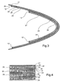
figure 3 is a schematic cross section view of a second embodiment of a leading edge structure according to the invention; -
figure 4 illustrates a multi-layered structure given by the overlapping of multilayer panels of the type offigure 3 , with an enlarged scale; and -
figures 5 and 6 are perspective views which illustrate two examples of honeycomb layers suitable for being included in the multilayer panels offigures 1-3 . - Firstly, referring to
figure 1 , a leading edge structure of a wing or of an empennage is wholly indicated withreference numeral 10. In the following description we shall use the terms "front", "outer" and "inner". The term "front" refers to the forward direction of the aircraft, whereas the terms "outer" and "inner" generally refer to a condition in which the leading edge structure is assembled to the rest of the wing or of the empennage, so that the "inner" elements are enclosed in the inner wing or empennage structure. - The leading
edge structure 10 constitutes the front portion of a wing profile. Thestructure 10 is formed by an overlapping of a plurality ofmultilayer panels 20 suitably curved with concavities facing towards a direction defined as "rear" with respect to the forward direction of an aircraft. - Each multilayer panel has at least the following layers:
- a first
outermost metal layer 21, consisting of a foil preferably of aluminium or aluminium alloy, and preferably having a thickness of between 0.2 mm and 0.5 mm; - a second
intermediate layer 22 of fibreglass having a thickness preferably between 0.1 mm and 0.5 mm, but possibly also up to 1 mm; - a third
honeycomb metal layer 23 having a thickness of between about 0.6 cm and about 2.5 cm, comprising walls locally perpendicular to the surface on which the layer lies. - The intermediate layer of
fibreglass 22 is connected to the adjacent layers through respective structuraladhesive film layers 25. Alternatively, a self-adhesive fibreglass can be chosen. - The succession of the
layers modular panel 20 can be repeated many times depending on the design requirements. Indeed, the third honeycomb layer is securely fixed, by means of adhesives, to a subsequent aluminium foil which, in the embodiment illustrated infigure 1 , constitutes the first outermost layer of asubsequent panel 20 having a convex profile oriented in the same direction as the profile of the outermost panel. In the embodiment offigures 3 and 4 , however, eachmultilayer panel 20 comprises afourth layer 24 consisting of a last aluminium foil which is fixed to thethird layer 23 of the same panel by means of adhesives. The two panels are then fixed to one another through an adhesive 25 applied between the fourthaluminium foil layer 24 of a panel and the first aluminium foil layer of an adjacent panel. - Z-shaped fibreglass closing cross pieces are indicated with
reference numeral 12, said cross pieces being suitable for sealing the peripheral edges of themultilayer panels 20. It is preferable to choose multilayer panels of the type having afurther aluminium foil 24 for the innermost panels, so as to uninterruptedly cover thehoneycomb layers 23 of the panels located in this position. - Men skilled in the art should understand that the number of overlapping
curved panels 20, and thus the overall thickness of the leading edge, is variable according to the structural requirements of the wing or of the empennage to be constructed. - The aluminium foils are fundamentally used as elements for fastening the fibreglass layers. The structural characteristics of high mechanical resistance and resilience of fibreglass, intimately and securely fixed together with the metal honeycomb and with the aluminium foil, provide a bridging effect which contributes to absorbing a substantial fraction of the elasto-plastic energy of deformation caused by impact. At the same time, the invention exploits the ability of the metal honeycomb layer for absorbing another large amount of energy caused by impact. Indeed, the honeycomb layer crushes only in the area in which the impact occurs. Therefore, the damage does not propagate to other parts of the wing or of the empennage. The honeycomb layer mainly has a structural function, since it determines the overall rigidity of the leading edge with the advantage of significantly reducing the overall weight of the wing with respect to conventional structures. The honeycomb layers illustrated, as an example, in
figures 5 and 6 , having slightly undulated walls and available on the market under the names Flex-Core® and Double-Flex®, are ideally meant for following single curvature profiles, double slight curvature profiles (figure 6 ) or double high curvature profiles (figure 5 ). - Experiments carried out by the Applicants have demonstrated that a wing structure constructed according to the present invention allows weight to be saved, having equal overall deformation of the leading edge at the impact zone, of the order of 30% with respect to a structure having comparable rigidity constructed with Glare® technology.
- It should be understood that the invention is not limited to the embodiments described and illustrated hereby, said embodiments should be considered example embodiments of the leading edge; the invention can, however, undergo modifications relative to its shape, size, and the arrangement of its constructive details, as defined by the appended claims. For example, the order of the single layers forming the panels can be inverted with respect to what has been illustrated in the present examples, by arranging the first
metal foil layer 21 further inside, and the third honeycomb layer (or the fourthmetal foil layer 24, if it is foreseen) further outside with respect to the wing or empennage structure. Furthermore, although the foregoing specification refers to aluminum and its alloys for the construction of themetal layers
Claims (15)
- A leading edge structure (10) for aircraft wings and empennages, comprising two or more multilayer panels (20) at least partially overlapping and suitably curved with at least partially congruent concavities, characterized in that each multilayer panel includes at least the following three layers:- a first layer (21) consisting of a metal foil,- a second intermediate layer (22) of fibre-glass, fixedly secured to the first layer (21), and- a third honeycomb metal layer (23) securely fixed to the second layer (22).
- A leading edge structure according to claim 1, characterised in that at least one of the panels comprises a fourth layer (24) consisting of a further metal foil.
- A leading edge structure according to claim 1 or 2, characterised in that, in each panel (20) layers are fixed to one another by means of adhesives.
- A leading edge structure according to claim 1, 2 or 3, characterised in that two adjacent and at least partially overlapping panels (20) are fixed to one another by means of adhesives.
- A leading edge structure according to claim 4 when dependent on claim 1, characterised in that the third metal honeycomb layer (23) of a given panel is fixed by means of adhesives to the first metal foil layer (21) of another panel at least partially overlapping said given panel.
- A leading edge structure according to claim 4 when dependent on claim 2, characterised in that the fourth metal foil layer (24) of a given panel is fixed by means of adhesive to the first metal foil layer (21) of another panel at least partially overlapping said given panel.
- A leading edge structure according to any one of the preceding claims, characterised in that said metal foil layers (21, 24) are made of aluminium or alloys thereof.
- A leading edge structure according to any one of the preceding claims, characterised in that said metal foil layers (21, 24) have a thickness ranging between about 0.2 mm and about 0.5 mm.
- A leading edge structure according to any one of the preceding claims, characterised in that the second fibreglass layer (22) has a thickness ranging between about 0.1 and about 1 mm, preferably between 0.2 and 0.5 mm.
- A leading edge structure according to any one of the preceding claims, characterised in that the third metal honeycomb layer (23) is made of aluminium or alloys thereof.
- A leading edge structure according to any one of the preceding claims, characterised in that the third honeycomb metal layer (23) has a thickness ranging between about 0.6 cm and about 2.5 cm.
- A leading edge structure according to any one of the preceding claims, characterised in that the third honeycomb metal layer (23) includes walls locally perpendicular to the surface on which that layer lies.
- A leading edge structure according to claim 12, characterised in that the walls of the honey-comb layer (23) have an undulating shape.
- A leading edge structure according to any one of the preceding claims, characterised in that in each panel (20) the first layer (21) is the outer-most.
- A leading edge structure according to any one of claims 1 to 13, characterised in that in each panel (20) the first layer (21) is the innermost.
Applications Claiming Priority (1)
| Application Number | Priority Date | Filing Date | Title |
|---|---|---|---|
| ITTO2008A000912A IT1392320B1 (en) | 2008-12-09 | 2008-12-09 | ATTACK EDGE FOR WINGS AND AIRCRAFT MAKES |
Publications (2)
| Publication Number | Publication Date |
|---|---|
| EP2196309A1 EP2196309A1 (en) | 2010-06-16 |
| EP2196309B1 true EP2196309B1 (en) | 2011-11-09 |
Family
ID=40908394
Family Applications (1)
| Application Number | Title | Priority Date | Filing Date |
|---|---|---|---|
| EP09177579A Active EP2196309B1 (en) | 2008-12-09 | 2009-12-01 | Leading edge for aircraft wings and empennages |
Country Status (6)
| Country | Link |
|---|---|
| US (1) | US8245972B2 (en) |
| EP (1) | EP2196309B1 (en) |
| JP (1) | JP5424830B2 (en) |
| AT (1) | ATE532626T1 (en) |
| ES (1) | ES2376089T3 (en) |
| IT (1) | IT1392320B1 (en) |
Cited By (1)
| Publication number | Priority date | Publication date | Assignee | Title |
|---|---|---|---|---|
| WO2025229479A1 (en) | 2024-04-29 | 2025-11-06 | Leonardo S.P.A. | Leading edge system for an aircraft, provided with an assembly for absorbing impacts |
Families Citing this family (20)
| Publication number | Priority date | Publication date | Assignee | Title |
|---|---|---|---|---|
| CN101269553B (en) * | 2008-05-09 | 2010-12-08 | 大连交通大学 | Magnesium Alloy Honeycomb Panel and Its Production Process |
| ITMI20080886A1 (en) * | 2008-05-15 | 2009-11-16 | Alenia Aermacchi Spa | JOINT TO INDUCE HIGH TEMPERATURE FALLS BETWEEN CONNECTED PARTS ON A AIRCRAFT |
| CN102030102B (en) * | 2010-11-18 | 2013-05-08 | 西北工业大学 | Horizontal tail front edge for bird strike-resisting airplane |
| KR101347369B1 (en) * | 2011-09-02 | 2014-01-07 | 삼성중공업 주식회사 | Blade for wind turbine, and wind turbine having the same |
| EP2785587A4 (en) * | 2011-11-30 | 2015-08-19 | Airbus Sas | Component having a box structure for an airplane airfoil |
| GB201120707D0 (en) | 2011-12-01 | 2012-01-11 | Airbus Operations Ltd | Leading edge structure |
| US9708030B1 (en) * | 2011-12-08 | 2017-07-18 | The Boeing Company | Impact-energy tolerant method and structures |
| US8968437B2 (en) * | 2012-05-02 | 2015-03-03 | Michael J Kline | Jet engine with deflector |
| FR2993857B1 (en) * | 2012-07-26 | 2015-03-27 | Airbus Operations Sas | DEVICE FOR PROTECTING A LONGERON STRUCTURE BEFORE A CENTRAL AIRCRAFT WING BOX AND AT LEAST ONE EQUIPMENT LOCATED IN THE SAME |
| CN103057690A (en) * | 2012-12-21 | 2013-04-24 | 中国商用飞机有限责任公司 | Aircraft airfoil leading edge structure |
| CN104002977B (en) * | 2014-05-06 | 2017-01-18 | 嘉兴美盾航空材料有限公司 | Bird-striking-preventing blocking plate and preparing technology thereof |
| US9896190B1 (en) * | 2014-05-07 | 2018-02-20 | The Boeing Company | Wing leading edge architecture suitable for laminar flow |
| US9592898B1 (en) | 2014-10-22 | 2017-03-14 | Allen L. Davies, Jr. | Airframe |
| CN105048102B (en) * | 2015-06-10 | 2018-01-19 | 湖北三江航天江北机械工程有限公司 | Bore barrel-shaped heat shield inwall bonding wave absorbing patch and the method for aluminium foil |
| ES2991889T3 (en) * | 2016-09-27 | 2024-12-05 | Siemens Gamesa Renewable Energy As | Protective cover system |
| EP3318481B1 (en) * | 2016-11-04 | 2020-07-08 | Airbus Operations, S.L. | Panel structure for an aircraft and manufacturing method thereof |
| US10556701B2 (en) * | 2017-04-14 | 2020-02-11 | Rohr, Inc. | Bird-strike energy absorbing net |
| FR3070369B1 (en) * | 2017-08-30 | 2019-08-23 | Airbus Operations | METHOD FOR MANUFACTURING AN AIRCRAFT ATTACK EDGE PANEL FOR OBTAINING EXTENDED LAMINAR FLOW, ATTACHING EDGE COMPRISING AT LEAST ONE PANEL OBTAINED FROM SAID METHOD |
| DE102017128497A1 (en) | 2017-11-30 | 2019-06-06 | Airbus Operations Gmbh | Leading edge arrangement for a flow body of a vehicle |
| CN119460137A (en) * | 2024-12-17 | 2025-02-18 | 中国航空工业集团公司西安飞机设计研究所 | A bird-strike-resistant aircraft leading edge ply structure |
Family Cites Families (28)
| Publication number | Priority date | Publication date | Assignee | Title |
|---|---|---|---|---|
| NL89352C (en) * | 1957-02-20 | 1900-01-01 | ||
| US3097982A (en) * | 1960-06-06 | 1963-07-16 | Eugene M Stoner | Method of fabricating airfoils |
| GB1120381A (en) * | 1964-07-07 | 1968-07-17 | Handley Page Ltd | Improvements in or relating to the manufacture of aerodynamic structures |
| US3490983A (en) * | 1965-05-17 | 1970-01-20 | Hitco | Fiber reinforced structures and methods of making the same |
| US4411380A (en) * | 1981-06-30 | 1983-10-25 | The United States Of America As Represented By The Administrator Of The National Aeronautics And Space Administration | Metal matrix composite structural panel construction |
| US4599255A (en) * | 1981-12-28 | 1986-07-08 | The Boeing Company | Composite structures having conductive surfaces |
| US4542056A (en) * | 1983-08-26 | 1985-09-17 | The Boeing Company | Composite structure having conductive surfaces |
| WO1985001489A1 (en) * | 1983-09-29 | 1985-04-11 | The Boeing Company | High strength to weight horizontal and vertical aircraft stabilizer |
| FR2616409B1 (en) * | 1987-06-09 | 1989-09-15 | Aerospatiale | BLADE OF COMPOSITE MATERIALS AND MANUFACTURING METHOD THEREOF |
| DE3816582A1 (en) * | 1988-05-15 | 1989-11-23 | Messerschmitt Boelkow Blohm | METHOD FOR PRODUCING A INSTALLATION ELEMENT AND INSTALLATION ELEMENT |
| US4879152A (en) * | 1989-02-15 | 1989-11-07 | Green Patrick H | Composite panel structure |
| US5106668A (en) * | 1989-06-07 | 1992-04-21 | Hexcel Corporation | Multi-layer honeycomb structure |
| US5123814A (en) * | 1990-07-27 | 1992-06-23 | The Marley Cooling Tower Company | Industrial cooling tower fan blade having abrasion resistant leading edge |
| US5567500A (en) * | 1991-08-07 | 1996-10-22 | Speciality Cellular Products Company | Composite honeycomb core structure comprising cell walls constructed of at least three unidirectional fiber layers or at least two unidirectional fiber layers and a random fiber layer |
| US5445861A (en) * | 1992-09-04 | 1995-08-29 | The Boeing Company | Lightweight honeycomb panel structure |
| US5344280A (en) * | 1993-05-05 | 1994-09-06 | General Electric Company | Impact resistant fan case liner |
| JPH07165197A (en) * | 1993-12-14 | 1995-06-27 | Nec Corp | Honeycomb panel for satelite |
| US5604010A (en) * | 1996-01-11 | 1997-02-18 | Hartz; Dale E. | Composite honeycomb sandwich structure |
| US5685940A (en) * | 1996-03-20 | 1997-11-11 | The Boeing Company | Adhering tiedown plies in composite construction |
| US5789060A (en) * | 1996-07-29 | 1998-08-04 | Specialty Cellular Products Company | Heat conduction honeycomb core |
| US6180206B1 (en) * | 1997-09-19 | 2001-01-30 | The Boeing Company | Composite honeycomb sandwich panel for fixed leading edges |
| US6612217B1 (en) * | 1998-06-02 | 2003-09-02 | Sri International | Penetration resistant fabric structures and materials |
| US6568310B2 (en) * | 2001-10-25 | 2003-05-27 | Timothy W. Morgan | Lightweight armored panels and doors |
| US20050175813A1 (en) * | 2004-02-10 | 2005-08-11 | Wingert A. L. | Aluminum-fiber laminate |
| US7988809B2 (en) * | 2004-09-01 | 2011-08-02 | Hexcel Corporation | Aircraft floor and interior panels using edge coated honeycomb |
| JP2007170328A (en) * | 2005-12-26 | 2007-07-05 | Toray Ind Inc | Wind turbine blade for wind power generation and method for manufacturing the same |
| US7628358B2 (en) * | 2006-10-26 | 2009-12-08 | The Boeing Company | Wing panel structure |
| US7866605B2 (en) * | 2007-04-24 | 2011-01-11 | The Boeing Company | Energy absorbing impact band and method |
-
2008
- 2008-12-09 IT ITTO2008A000912A patent/IT1392320B1/en active
-
2009
- 2009-11-19 JP JP2009263592A patent/JP5424830B2/en not_active Expired - Fee Related
- 2009-12-01 ES ES09177579T patent/ES2376089T3/en active Active
- 2009-12-01 EP EP09177579A patent/EP2196309B1/en active Active
- 2009-12-01 AT AT09177579T patent/ATE532626T1/en active
- 2009-12-09 US US12/634,402 patent/US8245972B2/en not_active Expired - Fee Related
Cited By (1)
| Publication number | Priority date | Publication date | Assignee | Title |
|---|---|---|---|---|
| WO2025229479A1 (en) | 2024-04-29 | 2025-11-06 | Leonardo S.P.A. | Leading edge system for an aircraft, provided with an assembly for absorbing impacts |
Also Published As
| Publication number | Publication date |
|---|---|
| JP5424830B2 (en) | 2014-02-26 |
| ITTO20080912A1 (en) | 2010-06-10 |
| IT1392320B1 (en) | 2012-02-24 |
| ATE532626T1 (en) | 2011-11-15 |
| US8245972B2 (en) | 2012-08-21 |
| ES2376089T3 (en) | 2012-03-08 |
| US20100140405A1 (en) | 2010-06-10 |
| JP2010137850A (en) | 2010-06-24 |
| EP2196309A1 (en) | 2010-06-16 |
Similar Documents
| Publication | Publication Date | Title |
|---|---|---|
| US8245972B2 (en) | Leading edge for aircraft wings and empennages | |
| US8434716B2 (en) | Compliant crown panel for an aircraft | |
| EP2117922B1 (en) | Compliant panel for aircraft | |
| EP2070816B1 (en) | Methods and apparatus for an integrated aerodynamic panel | |
| US6729576B2 (en) | Composite tail cone assembly | |
| CN108016600B (en) | Panel structure for an aircraft and method for the production thereof | |
| EP2259965B1 (en) | Pressure bulkhead for aircraft | |
| US7285326B2 (en) | Lightweight structure particularly for an aircraft | |
| EP2727824A2 (en) | Reinforced aircraft fuselage | |
| EP4140877B1 (en) | Slat for an aircraft wing, method for manufacturing such a slat | |
| US10604226B2 (en) | Shielded structure for aircraft | |
| EP2257466B1 (en) | Burn through resistant aircraft fuselage | |
| EP1701881B1 (en) | Aircraft fuselage | |
| WO2014094549A1 (en) | Aeroplane airfoil leading edge structure | |
| US20230031989A1 (en) | Reinforced leading edge section for an aircraft | |
| EP3498591A1 (en) | A composite truss beam with a sandwich web |
Legal Events
| Date | Code | Title | Description |
|---|---|---|---|
| PUAI | Public reference made under article 153(3) epc to a published international application that has entered the european phase |
Free format text: ORIGINAL CODE: 0009012 |
|
| AK | Designated contracting states |
Kind code of ref document: A1 Designated state(s): AT BE BG CH CY CZ DE DK EE ES FI FR GB GR HR HU IE IS IT LI LT LU LV MC MK MT NL NO PL PT RO SE SI SK SM TR |
|
| AX | Request for extension of the european patent |
Extension state: AL BA RS |
|
| 17P | Request for examination filed |
Effective date: 20101215 |
|
| GRAP | Despatch of communication of intention to grant a patent |
Free format text: ORIGINAL CODE: EPIDOSNIGR1 |
|
| RIC1 | Information provided on ipc code assigned before grant |
Ipc: B32B 15/14 20060101ALI20110415BHEP Ipc: B32B 3/12 20060101AFI20110415BHEP |
|
| GRAS | Grant fee paid |
Free format text: ORIGINAL CODE: EPIDOSNIGR3 |
|
| GRAA | (expected) grant |
Free format text: ORIGINAL CODE: 0009210 |
|
| AK | Designated contracting states |
Kind code of ref document: B1 Designated state(s): AT BE BG CH CY CZ DE DK EE ES FI FR GB GR HR HU IE IS IT LI LT LU LV MC MK MT NL NO PL PT RO SE SI SK SM TR |
|
| REG | Reference to a national code |
Ref country code: GB Ref legal event code: FG4D |
|
| REG | Reference to a national code |
Ref country code: CH Ref legal event code: EP |
|
| REG | Reference to a national code |
Ref country code: IE Ref legal event code: FG4D |
|
| REG | Reference to a national code |
Ref country code: DE Ref legal event code: R096 Ref document number: 602009003581 Country of ref document: DE Effective date: 20120119 |
|
| REG | Reference to a national code |
Ref country code: NL Ref legal event code: VDEP Effective date: 20111109 |
|
| REG | Reference to a national code |
Ref country code: ES Ref legal event code: FG2A Ref document number: 2376089 Country of ref document: ES Kind code of ref document: T3 Effective date: 20120308 |
|
| LTIE | Lt: invalidation of european patent or patent extension |
Effective date: 20111109 |
|
| PG25 | Lapsed in a contracting state [announced via postgrant information from national office to epo] |
Ref country code: NO Free format text: LAPSE BECAUSE OF FAILURE TO SUBMIT A TRANSLATION OF THE DESCRIPTION OR TO PAY THE FEE WITHIN THE PRESCRIBED TIME-LIMIT Effective date: 20120209 Ref country code: LT Free format text: LAPSE BECAUSE OF FAILURE TO SUBMIT A TRANSLATION OF THE DESCRIPTION OR TO PAY THE FEE WITHIN THE PRESCRIBED TIME-LIMIT Effective date: 20111109 Ref country code: IS Free format text: LAPSE BECAUSE OF FAILURE TO SUBMIT A TRANSLATION OF THE DESCRIPTION OR TO PAY THE FEE WITHIN THE PRESCRIBED TIME-LIMIT Effective date: 20120309 |
|
| PG25 | Lapsed in a contracting state [announced via postgrant information from national office to epo] |
Ref country code: BE Free format text: LAPSE BECAUSE OF FAILURE TO SUBMIT A TRANSLATION OF THE DESCRIPTION OR TO PAY THE FEE WITHIN THE PRESCRIBED TIME-LIMIT Effective date: 20111109 Ref country code: PL Free format text: LAPSE BECAUSE OF FAILURE TO SUBMIT A TRANSLATION OF THE DESCRIPTION OR TO PAY THE FEE WITHIN THE PRESCRIBED TIME-LIMIT Effective date: 20111109 Ref country code: PT Free format text: LAPSE BECAUSE OF FAILURE TO SUBMIT A TRANSLATION OF THE DESCRIPTION OR TO PAY THE FEE WITHIN THE PRESCRIBED TIME-LIMIT Effective date: 20120309 Ref country code: SI Free format text: LAPSE BECAUSE OF FAILURE TO SUBMIT A TRANSLATION OF THE DESCRIPTION OR TO PAY THE FEE WITHIN THE PRESCRIBED TIME-LIMIT Effective date: 20111109 Ref country code: SE Free format text: LAPSE BECAUSE OF FAILURE TO SUBMIT A TRANSLATION OF THE DESCRIPTION OR TO PAY THE FEE WITHIN THE PRESCRIBED TIME-LIMIT Effective date: 20111109 Ref country code: LV Free format text: LAPSE BECAUSE OF FAILURE TO SUBMIT A TRANSLATION OF THE DESCRIPTION OR TO PAY THE FEE WITHIN THE PRESCRIBED TIME-LIMIT Effective date: 20111109 Ref country code: NL Free format text: LAPSE BECAUSE OF FAILURE TO SUBMIT A TRANSLATION OF THE DESCRIPTION OR TO PAY THE FEE WITHIN THE PRESCRIBED TIME-LIMIT Effective date: 20111109 Ref country code: GR Free format text: LAPSE BECAUSE OF FAILURE TO SUBMIT A TRANSLATION OF THE DESCRIPTION OR TO PAY THE FEE WITHIN THE PRESCRIBED TIME-LIMIT Effective date: 20120210 Ref country code: HR Free format text: LAPSE BECAUSE OF FAILURE TO SUBMIT A TRANSLATION OF THE DESCRIPTION OR TO PAY THE FEE WITHIN THE PRESCRIBED TIME-LIMIT Effective date: 20111109 |
|
| RAP2 | Party data changed (patent owner data changed or rights of a patent transferred) |
Owner name: ALENIA AERMACCHI S.P.A. |
|
| REG | Reference to a national code |
Ref country code: DE Ref legal event code: R082 Ref document number: 602009003581 Country of ref document: DE Representative=s name: MITSCHERLICH & PARTNER PATENT- UND RECHTSANWAE, DE |
|
| PG25 | Lapsed in a contracting state [announced via postgrant information from national office to epo] |
Ref country code: CY Free format text: LAPSE BECAUSE OF FAILURE TO SUBMIT A TRANSLATION OF THE DESCRIPTION OR TO PAY THE FEE WITHIN THE PRESCRIBED TIME-LIMIT Effective date: 20111109 |
|
| REG | Reference to a national code |
Ref country code: FR Ref legal event code: CA Effective date: 20120625 Ref country code: FR Ref legal event code: CD Owner name: ALENIA AERMACCHI S.P.A., IT Effective date: 20120625 |
|
| PG25 | Lapsed in a contracting state [announced via postgrant information from national office to epo] |
Ref country code: BG Free format text: LAPSE BECAUSE OF FAILURE TO SUBMIT A TRANSLATION OF THE DESCRIPTION OR TO PAY THE FEE WITHIN THE PRESCRIBED TIME-LIMIT Effective date: 20120209 Ref country code: EE Free format text: LAPSE BECAUSE OF FAILURE TO SUBMIT A TRANSLATION OF THE DESCRIPTION OR TO PAY THE FEE WITHIN THE PRESCRIBED TIME-LIMIT Effective date: 20111109 Ref country code: SK Free format text: LAPSE BECAUSE OF FAILURE TO SUBMIT A TRANSLATION OF THE DESCRIPTION OR TO PAY THE FEE WITHIN THE PRESCRIBED TIME-LIMIT Effective date: 20111109 Ref country code: MC Free format text: LAPSE BECAUSE OF NON-PAYMENT OF DUE FEES Effective date: 20111231 Ref country code: DK Free format text: LAPSE BECAUSE OF FAILURE TO SUBMIT A TRANSLATION OF THE DESCRIPTION OR TO PAY THE FEE WITHIN THE PRESCRIBED TIME-LIMIT Effective date: 20111109 Ref country code: CZ Free format text: LAPSE BECAUSE OF FAILURE TO SUBMIT A TRANSLATION OF THE DESCRIPTION OR TO PAY THE FEE WITHIN THE PRESCRIBED TIME-LIMIT Effective date: 20111109 |
|
| REG | Reference to a national code |
Ref country code: DE Ref legal event code: R081 Ref document number: 602009003581 Country of ref document: DE Owner name: ALENIA AERMACCHI S.P.A., IT Free format text: FORMER OWNER: ALENIA AERONAUTICA S.P.A., POMIGLIANO D ARCO, IT Effective date: 20120613 Ref country code: DE Ref legal event code: R082 Ref document number: 602009003581 Country of ref document: DE Representative=s name: MITSCHERLICH & PARTNER PATENT- UND RECHTSANWAE, DE Effective date: 20120613 Ref country code: DE Ref legal event code: R082 Ref document number: 602009003581 Country of ref document: DE Representative=s name: MITSCHERLICH, PATENT- UND RECHTSANWAELTE PARTM, DE Effective date: 20120613 Ref country code: DE Ref legal event code: R081 Ref document number: 602009003581 Country of ref document: DE Owner name: ALENIA AERMACCHI S.P.A., VENEGONO SUPERIORE, IT Free format text: FORMER OWNER: ALENIA AERONAUTICA S.P.A., POMIGLIANO D ARCO, NAPOLI, IT Effective date: 20120613 Ref country code: DE Ref legal event code: R082 Ref document number: 602009003581 Country of ref document: DE Representative=s name: MITSCHERLICH, PATENT- UND RECHTSANWAELTE, PART, DE Effective date: 20120613 |
|
| PG25 | Lapsed in a contracting state [announced via postgrant information from national office to epo] |
Ref country code: RO Free format text: LAPSE BECAUSE OF FAILURE TO SUBMIT A TRANSLATION OF THE DESCRIPTION OR TO PAY THE FEE WITHIN THE PRESCRIBED TIME-LIMIT Effective date: 20111109 |
|
| PLBE | No opposition filed within time limit |
Free format text: ORIGINAL CODE: 0009261 |
|
| STAA | Information on the status of an ep patent application or granted ep patent |
Free format text: STATUS: NO OPPOSITION FILED WITHIN TIME LIMIT |
|
| REG | Reference to a national code |
Ref country code: AT Ref legal event code: MK05 Ref document number: 532626 Country of ref document: AT Kind code of ref document: T Effective date: 20111109 |
|
| REG | Reference to a national code |
Ref country code: IE Ref legal event code: MM4A |
|
| 26N | No opposition filed |
Effective date: 20120810 |
|
| PG25 | Lapsed in a contracting state [announced via postgrant information from national office to epo] |
Ref country code: IE Free format text: LAPSE BECAUSE OF NON-PAYMENT OF DUE FEES Effective date: 20111201 |
|
| REG | Reference to a national code |
Ref country code: DE Ref legal event code: R097 Ref document number: 602009003581 Country of ref document: DE Effective date: 20120810 |
|
| PG25 | Lapsed in a contracting state [announced via postgrant information from national office to epo] |
Ref country code: AT Free format text: LAPSE BECAUSE OF FAILURE TO SUBMIT A TRANSLATION OF THE DESCRIPTION OR TO PAY THE FEE WITHIN THE PRESCRIBED TIME-LIMIT Effective date: 20111109 |
|
| PG25 | Lapsed in a contracting state [announced via postgrant information from national office to epo] |
Ref country code: MT Free format text: LAPSE BECAUSE OF FAILURE TO SUBMIT A TRANSLATION OF THE DESCRIPTION OR TO PAY THE FEE WITHIN THE PRESCRIBED TIME-LIMIT Effective date: 20111109 Ref country code: MK Free format text: LAPSE BECAUSE OF FAILURE TO SUBMIT A TRANSLATION OF THE DESCRIPTION OR TO PAY THE FEE WITHIN THE PRESCRIBED TIME-LIMIT Effective date: 20111109 |
|
| PG25 | Lapsed in a contracting state [announced via postgrant information from national office to epo] |
Ref country code: SM Free format text: LAPSE BECAUSE OF FAILURE TO SUBMIT A TRANSLATION OF THE DESCRIPTION OR TO PAY THE FEE WITHIN THE PRESCRIBED TIME-LIMIT Effective date: 20111109 |
|
| PG25 | Lapsed in a contracting state [announced via postgrant information from national office to epo] |
Ref country code: LU Free format text: LAPSE BECAUSE OF NON-PAYMENT OF DUE FEES Effective date: 20111201 |
|
| PG25 | Lapsed in a contracting state [announced via postgrant information from national office to epo] |
Ref country code: FI Free format text: LAPSE BECAUSE OF FAILURE TO SUBMIT A TRANSLATION OF THE DESCRIPTION OR TO PAY THE FEE WITHIN THE PRESCRIBED TIME-LIMIT Effective date: 20111109 |
|
| PG25 | Lapsed in a contracting state [announced via postgrant information from national office to epo] |
Ref country code: TR Free format text: LAPSE BECAUSE OF FAILURE TO SUBMIT A TRANSLATION OF THE DESCRIPTION OR TO PAY THE FEE WITHIN THE PRESCRIBED TIME-LIMIT Effective date: 20111109 |
|
| PG25 | Lapsed in a contracting state [announced via postgrant information from national office to epo] |
Ref country code: HU Free format text: LAPSE BECAUSE OF FAILURE TO SUBMIT A TRANSLATION OF THE DESCRIPTION OR TO PAY THE FEE WITHIN THE PRESCRIBED TIME-LIMIT Effective date: 20111109 |
|
| PGFP | Annual fee paid to national office [announced via postgrant information from national office to epo] |
Ref country code: IT Payment date: 20131210 Year of fee payment: 5 |
|
| REG | Reference to a national code |
Ref country code: CH Ref legal event code: PL |
|
| PG25 | Lapsed in a contracting state [announced via postgrant information from national office to epo] |
Ref country code: LI Free format text: LAPSE BECAUSE OF NON-PAYMENT OF DUE FEES Effective date: 20131231 Ref country code: CH Free format text: LAPSE BECAUSE OF NON-PAYMENT OF DUE FEES Effective date: 20131231 |
|
| PG25 | Lapsed in a contracting state [announced via postgrant information from national office to epo] |
Ref country code: IT Free format text: LAPSE BECAUSE OF NON-PAYMENT OF DUE FEES Effective date: 20141201 |
|
| REG | Reference to a national code |
Ref country code: FR Ref legal event code: PLFP Year of fee payment: 7 |
|
| REG | Reference to a national code |
Ref country code: FR Ref legal event code: PLFP Year of fee payment: 8 |
|
| REG | Reference to a national code |
Ref country code: FR Ref legal event code: PLFP Year of fee payment: 9 |
|
| PGFP | Annual fee paid to national office [announced via postgrant information from national office to epo] |
Ref country code: GB Payment date: 20241224 Year of fee payment: 16 |
|
| PGFP | Annual fee paid to national office [announced via postgrant information from national office to epo] |
Ref country code: FR Payment date: 20241127 Year of fee payment: 16 |
|
| PGFP | Annual fee paid to national office [announced via postgrant information from national office to epo] |
Ref country code: DE Payment date: 20241227 Year of fee payment: 16 |
|
| PGFP | Annual fee paid to national office [announced via postgrant information from national office to epo] |
Ref country code: ES Payment date: 20250102 Year of fee payment: 16 |