EP2196294A1 - Cutting machine - Google Patents
Cutting machine Download PDFInfo
- Publication number
- EP2196294A1 EP2196294A1 EP08833404A EP08833404A EP2196294A1 EP 2196294 A1 EP2196294 A1 EP 2196294A1 EP 08833404 A EP08833404 A EP 08833404A EP 08833404 A EP08833404 A EP 08833404A EP 2196294 A1 EP2196294 A1 EP 2196294A1
- Authority
- EP
- European Patent Office
- Prior art keywords
- cutting
- whetstone
- sharpening
- cutting edge
- cutting blade
- Prior art date
- Legal status (The legal status is an assumption and is not a legal conclusion. Google has not performed a legal analysis and makes no representation as to the accuracy of the status listed.)
- Granted
Links
Images





Classifications
-
- B—PERFORMING OPERATIONS; TRANSPORTING
- B26—HAND CUTTING TOOLS; CUTTING; SEVERING
- B26D—CUTTING; DETAILS COMMON TO MACHINES FOR PERFORATING, PUNCHING, CUTTING-OUT, STAMPING-OUT OR SEVERING
- B26D7/00—Details of apparatus for cutting, cutting-out, stamping-out, punching, perforating, or severing by means other than cutting
- B26D7/08—Means for treating work or cutting member to facilitate cutting
- B26D7/12—Means for treating work or cutting member to facilitate cutting by sharpening the cutting member
-
- B—PERFORMING OPERATIONS; TRANSPORTING
- B24—GRINDING; POLISHING
- B24B—MACHINES, DEVICES, OR PROCESSES FOR GRINDING OR POLISHING; DRESSING OR CONDITIONING OF ABRADING SURFACES; FEEDING OF GRINDING, POLISHING, OR LAPPING AGENTS
- B24B3/00—Sharpening cutting edges, e.g. of tools; Accessories therefor, e.g. for holding the tools
- B24B3/36—Sharpening cutting edges, e.g. of tools; Accessories therefor, e.g. for holding the tools of cutting blades
- B24B3/368—Sharpening cutting edges, e.g. of tools; Accessories therefor, e.g. for holding the tools of cutting blades installed as an accessory on another machine
-
- B—PERFORMING OPERATIONS; TRANSPORTING
- B26—HAND CUTTING TOOLS; CUTTING; SEVERING
- B26F—PERFORATING; PUNCHING; CUTTING-OUT; STAMPING-OUT; SEVERING BY MEANS OTHER THAN CUTTING
- B26F1/00—Perforating; Punching; Cutting-out; Stamping-out; Apparatus therefor
- B26F1/38—Cutting-out; Stamping-out
- B26F1/3806—Cutting-out; Stamping-out wherein relative movements of tool head and work during cutting have a component tangential to the work surface
- B26F1/3813—Cutting-out; Stamping-out wherein relative movements of tool head and work during cutting have a component tangential to the work surface wherein the tool head is moved in a plane parallel to the work in a coordinate system fixed with respect to the work
- B26F1/382—Cutting-out; Stamping-out wherein relative movements of tool head and work during cutting have a component tangential to the work surface wherein the tool head is moved in a plane parallel to the work in a coordinate system fixed with respect to the work wherein the cutting member reciprocates in, or substantially in, a direction parallel to the cutting edge
-
- Y—GENERAL TAGGING OF NEW TECHNOLOGICAL DEVELOPMENTS; GENERAL TAGGING OF CROSS-SECTIONAL TECHNOLOGIES SPANNING OVER SEVERAL SECTIONS OF THE IPC; TECHNICAL SUBJECTS COVERED BY FORMER USPC CROSS-REFERENCE ART COLLECTIONS [XRACs] AND DIGESTS
- Y10—TECHNICAL SUBJECTS COVERED BY FORMER USPC
- Y10T—TECHNICAL SUBJECTS COVERED BY FORMER US CLASSIFICATION
- Y10T83/00—Cutting
- Y10T83/768—Rotatable disc tool pair or tool and carrier
- Y10T83/7684—With means to support work relative to tool[s]
Definitions
- the present invention relates to a cutting machine for cutting a sheet material and the like, or particularly to a cutting machine having the function of sharpening a cutting blade.
- Patent Citation 1 discloses a sheet material cutting machine for cutting the sheet material with a cutting knife which is moved in reciprocation along a vertical axis line and also discloses two different ways of sharpening the cutting knife from both sides of its cutting edge.
- Fig. 10 shows those two different concepts on the sharpening disclosed by Patent Citation 1.
- Fig. 10(a) shows one concept on the sharpening with a rounded surface around the outside of a rotary whetstone disclosed in its Fig. 11 and the like.
- Fig. 10(b) shows another concept on sharpening with a flat surface of the rotary whetstone perpendicular to an axis thereof disclosed in its Fig. 13 and the like.
- the simplified construction is illustrated, for explanatory convenience. Although names and reference numerals of parts may vary, the correspondence relation to the two different concepts on the sharperning should be obvious.
- FIG. 10(a) one side 1b of the cutting edge 1a of the cutting knife 1 and the other side 1c of the same are ground with cylindrical surfaces 2a, 3a of outer peripheries of two rotary whetstones 2, 3, respectively.
- the two rotary whetstones 2, 3 are supported at front ends of two arms 4a, 4b of a support block 4.
- the two arms 4a, 4b are fixed with spaced apart from each other at a certain angle.
- the support block 4 can be pivoted about or swung and displaced around a pivot shaft 5 penetrating intermediate portion between the arms 4a, 4b.
- the one side 1b of the cutting knife 1 or the other side 1c of the same can be ground with the related cylindrical surface 2a, 3a of the rotary whetstone 2, 3.
- the sharpening is performed using the cylindrical surface 2a, 3a, even when one side 1b and the other side 1c of the knife 1 initially have a linear cross-sectional shape, they are varied in cross-section to have a concave surface, as shown as a shaded area.
- Fig. 10(b) like reference numerals are labeled to corresponding parts to Fig. 10(a) , to avoid redundant explanation.
- the arms 4a, 4b mount the rotary whetstones 2, 3 on the sides facing the cutting edge 1a of the cutting knife 1, respectively.
- the rotary whetstones 2, 3 are away from the cutting knife 1 in the full-line state, they can be switched to the state in which the flat surfaces 2b, 3b perpendicular to the rotation shafts are put in contact with the one side 1b and the other side 1c of the knife 1, respectively, to sharpen them.
- the flat surface 2b of the rotary whetstone 2 is switched to the state of being put in contact with the one side 1b of the cutting knife 1 to sharpen it.
- the flat surface 3b of the rotary whetstone 3 is switched to the state of being put in contact with the other side 1c of the cutting knife 1 to sharpen it.
- the linear cross-sectional shape of the cutting knife 1 is kept unchanged, as shown as the shaded area.
- the cylindrical surfaces 2a, 2b of the rotary whetstones 2, 3 can be put in contact with the one side 1b of the cutting edge 1a of the cutting knife 1 and the other side 1c of the same, respectively, via a link mechanism and the like, not via an overall pivotal displacement of the support block 4 (Cf. Patent Citation 2, for example).
- Patent Citation 2 the rotary whetstones 2, 3 and the whetstone supporting structure are contained in the rotary cylinder which is turned around an R-axis as a rotation shaft of the cutting edge of the cutting blade equivalent to the cutting knife 1.
- the switching between the sharpening states is performed by turning the rotary cylinder while locking the rotation ring mounted on the rotary cylinder to be stationary relative to outside.
- a relative angular displacement between the rotation ring stationary with respect to outside and the rotary cylinder able to turn with respect to outside allows the rotary whetstones to pivotally displaced separately via the cams and the link mechanism, thereby allowing the switching between the sharpening states.
- Fig. 10(a) also shows that when being ground using the cylindrical surfaces 2a, 3a of the rotary whetstones 2, 3, the one side 1b of the cutting edge 1a and the other side 1c of the same which initially have a linear cross-sectional shape are varied in cross-section to have a concave surface, as shown as the shaded area.
- the cutting knife having the cross-section thus varied decreases in thickness at its portion close to the cutting edge 1c and thus decreases in rigidity, while on the other hand, it sharply increases in thickness at its portion away from such a decreased thickness portion in the vicinity of the cutting edge 1a, thereby producing an increased cutting resistance.
- the cutting knife 1 initially has a face of a curved cross-sectional shape, as shown as the shaded area. Even in this case, as the sharpening with the cylindrical surface 2a, 3a progresses, the decrease in thickness of the ground area on the side close to the cutting edge 1a becomes greater than on the shoulder side farthest from the cutting edge 1a and thus an angle of the cutting edge becomes greater. In either case, as long as the cutting knife is ground using the cylindrical surfaces 2a, 3a, the initial angle of the cutting edge cannot be kept unchanged.
- the present invention provides a cutting machine for cutting a sheet material to be cut, which is put on a cutting table, with a cutting blade provided in a cutting head movable along the cutting table, wherein the cutting blade is used while both sides of its cutting edge are ground to keep sharpness of the cutting edge, and the cutting head is provided with:
- said cutting head comprises:
- said whetstone holding mechanism is supported in spaced relation on front ends of a pair of swing arms which are supported capable with swing displacement at base end portions thereof on a pair of pivot shafts which are arranged in the rotary cylinder in standing relation, with spaced, at both sides of the cutting edge of the cutting blade and are parallel with the rotation shaft of the cutting edge, and said slide ring is provided with cams for guiding the whetstone holding mechanism to positions corresponding to the standby state, the one side sharpening state, and the other side sharpening state, respectively.
- said rotary cylinder is provided with a rotation ring which can be rotationally driven from outside and has an internal tooth around an inside thereof
- said whetstone holding mechanism is equipped with a gear to engage with the internal tooth of the rotation ring
- said cams are formed to guide the whetstone holding mechanism in such a manner as to change a position of the whetstone holding mechanism while keeping the engagement between the gear and the internal tooth of the rotation ring
- said one side use abrasive whetstone and said other side use abrasive whetstone are rotated by a rotational driving force transmitted from outside of the rotary cylinder to the gear through the rotation ring, to sharpen the cutting blade.
- the sharpening can be carried out in such a manner as to keep an angle of the cutting edge constant.
- the cutting blade sharpening elements are contained in the rotary cylinder able to turn around the rotation shaft of the cutting edge, and the selective switch between the sharpening states can be made at an angle of rotation of the rotary cylinder in the state in which the slide ring is locked by the lock mechanism.
- the whetstone holding mechanism is supported in spaced relation on front ends of a pair of swing arms which are supported capable with swing displacement at base end portions thereof to the rotary cylinder in spaced relation, a four-joint link mechanism is formed, respective sides of which are formed by the rotary cylinder, the pair of swing arms, and the whetstone holding mechanism.
- the mechanism for moving the one side use abrasive whetstone and the other side use abrasive whetstone, which are held by the whetstone holding mechanism, while keeping the state in which an angle formed between the both flat surfaces used for the sharpening corresponds to an angle of the cutting edge, can be made compact.
- the one side use abrasive whetstone and the other side use abrasive whetstone can be rotationally driven from outside of the rotary cylinder.
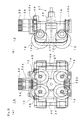
- Fig. 1 shows a cutting machine 10 of an embodiment of the present invention, simplistically showing a construction for sharpening a cutting blade 11.
- the cutting blade 11 has a cutting edge 11a formed by one slant side surface 11b and the other slant side surface 11c being joined together at their tips and has a pentagonal cross-sectional shape.
- the cutting blade 11 is driven to move in reciprocation in a direction perpendicular to paper and can cut a sheet material to a direction for the cutting edge 11a to point.
- a cutting head including a mechanism to support and drive the cutting blade 11 is moved in parallel with and over a cutting table on which the sheet material is carried so that the sheet material can be cut with the cutting edge 11a shifted in position or changed in direction to point.
- the cutting head is provided therein with a whetstone holding mechanism 15, placed in front of the cutting edge 11a of the cutting blade 11, for holding a pair of rotary whetstones 12, 13 via a support block 14.
- the support block 14 is provided with two arms 14a, 14b spaced at a certain angle, and rotation shafts 12a, 13a of the rotary whetstones 12, 13 extend upwards from the vicinities of front ends of the arms 14a, 14b, respectively.
- the rotary whetstones 12, 13 have, at front ends thereof, flat surfaces 12b, 13b perpendicular to the rotation shafts 12a, 13a to sharpen the one side 11b and the other side 11c of the cutting edge 11a of the cutting blade 11, respectively.
- the whetstone holding mechanism 15 can move in parallel linearly or can swing almost linearly, as mainly indicated by Arrow 15a, to bring the flat surface 12b of the rotary whetstone 12 into contact with the one side 11b of the cutting blade 11, as depicted by a broken line, thereby switching to the sharpening state.
- the whetstone holding mechanism 15 can move while keeping the one side 11b or the other side 11c of the cutting edge 11a of the cutting blade 11 in parallel with the flat surface 12b, 13b of the rotary whetstone 12, 13, to allow the selective switch between those sharpening states. Even when the process of sharpening progresses, since the parallelism between the flat surface 12b, 13b and the one side 11b or the other side 11c of the cutting blade is kept, the angle of the cutting edge is kept constant.
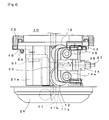
- Fig. 2 shows a schematic construction of the cutting head 20 used in the cutting machine 10 of Fig. 1 .
- the cutting head 20 includes the drive mechanism, placed over the cutting blade 11, for driving the cutting blade 11 in reciprocation, though omitting illustration.
- the turning of a rotary cylinder 21 allows the cutting blade 11 to turn around the R-axis as a cutting edge turning axis, to change the direction of cutting.
- a slide ring 22 is provided under the rotary cylinder 21, and a lock mechanism 23 is provided at the outside of the slide ring 22 so that the slide ring 22 can be locked to outside.
- the slide ring 22 follows the rotary cylinder 21 turning.
- the slide ring 22 is locked by the lock mechanism 23 so that only the rotary cylinder 21 is turned.
- the rotary cylinder 21 has legs 21 a extending downwards through the slide ring 22 and supporting a knife guide 25 thereon.
- the knife guide 25 supports the cutting blade 11 so that the cutting blade 11 can be prevented from being deformed or displaced when moved vertically.
- the legs 21a support a foot presser 26 at lower ends thereof.
- the foot presser 26 is to be put on the sheet material to be cut and the like.
- the whetstone holding mechanism 15 is supported at a position opposed to the knife guide 25 via a front end portion of a swing arm 37 and the like, as mentioned later.
- the swing arm 37 is supported at a base end thereof by the leg 21a to be freely pivoted.
- the whetstone holding mechanism 15 includes a cutting edge position detecting mechanism 27 for detecting a position of the cutting edge 11a of the cutting blade 11 and also detecting wear of the cutting blade 11 caused by the sharpening and the cutting of the cutting blade 11.
- the rotary cylinder 21 is supported by a support frame 28 of the cutting head 20 to be freely rotatable via a bearing 29.
- the lock mechanism 23 locks so that the slide ring 24 can be made stationary with respect to the support frame 28.
- the rotary cylinder 21 mounts thereon a pulley 21b to receive a rotational driving force from outside.
- the rotation ring 24 is supported to the rotary cylinder 21 via a bearing 30.
- a timing belt is wound around the rotation ring 24 to receive the rotational driving force to rotate the rotary whetstone 12, 13 via a gear 33 meshed with an internally-toothed gear.
- the details on the gear 33, a slide ring pivoted cam 43, a follower 45, a lever 49, and a pivot shaft 51 are described later.
- Fig. 3 shows the construction of the whetstone holding mechanism 15 of Fig. 2 .
- Fig. 3(a) shows the construction as viewed from the left side of Fig. 2
- Fig. 3(b) shows the construction as viewed from the front side of Fig. 2 .
- the rotary whetstones 12, 13 are arranged at vertically spaced places, two at each side of the mechanism.
- the rotary whetstone 12 is provided at a base portion thereof with a pulley 12a, around which a timing belt 31 is wound.
- the rotary whetstone 13 is also provided with a pulley 13c, as mentioned later.
- the single timing belt 31 in total runs around the rotary whetstones 12, 13 and upper and lower pulleys 32a, 32b.
- the upper pulley 32a is fixed to a lower end portion of a drive shaft 34 mounting the gear 33 on an upper end thereof.
- the lower pulley 32b rotates freely.
- the support block 14 is provided with support shafts 35, 36 and followers 45, 46 which are respectively arranged at spaced places.
- Fig. 4 shows the construction of sharpening the cutting blade 11 of Fig. 3 from which a swing arm 37 and some other parts are omitted.
- the knife guide 25 has a shape not to contact with the rotary whetstone 12 at the position where the cutting blade 11 is sharpened.
- the cutting blade 11 is moved vertically a stroke so that it can be uniformly sharpened in the longitudinal direction.
- One end of a tension spring 54 mentioned later is fixed to the lever 49.
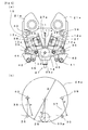
- Fig. 5 shows the whetstone holding mechanism 15 and the cutting blade 11 of Fig. 2 which are in the standby state for sharpening.
- Each of the following drawing figures shows the construction of the rotary cylinder 21 as viewed from below the downwardly extending legs 21a.
- Fig. 5(a) shows the construction in which the whetstone holding mechanism 15 is supported via a link mechanism.
- Fig. 5(b) shows a positional relation between four joints of the link mechanism for supporting the whetstone holding mechanism 15.
- the pair of swing arms 37, 38 are coupled at front ends thereof to the support shafts 35, 36 shown in Fig. 3(a) , to freely pivot about them.
- the swing arms 37, 38 are supported at their base ends by the pivot shafts 39, 40 provided on the legs 21 a of the rotary cylinder 21 so that they can be freely pivotally displaced.
- the pivoted cams 43, 44 are supported by pivot shafts 41, 42 supported by the slide ring 22, so that they can be freely pivotally displaced.
- the pivoted cam 43 is biased in a counterclockwise direction and the pivoted cam 44 is biased in a clockwise direction by respective springs, so that their cam surfaces are respectively put in contact with followers 45, 46 provided in the support block 14. In the standby state as illustrated, a tip of a pin 27a of the cutting edge position detecting mechanism 27 confronts the cutting edge 11a of the cutting blade 11.
- the rotary whetstones 12, 13 have a base made of metal and have a generally cylindrical shape having a flange at one end thereof.
- the flat surfaces 12b, 13b of the rotary whetstones 12, 13 are formed by allowing abrasive material, such as for example abrasive grain, adhere to the flange surface.
- the pulleys 12c, 13c around which the timing belt 31 is wound are mounted to the rotation shafts 12a, 13a at the base side of the rotary whetstones 12, 13.
- the pair of swing arms 37, 38 are pivotally displaced, with the pivot shafts 39, 40 as centers, so that centers of the support shafts 35, 36 can move along the arcs drawn with a certain radius R.
- a center of the drive shaft 34 of the gear 33 is also set to be on the arc drawn with the same radius R, the gear 33 can be moved so that its pitch circle 33p is always in contact with a pitch circle 24p of the internal teeth of the rotation ring 24.
- the support block 14 of the whetstone holding mechanism 15 is supported via the four-joint link structure with the centers of the pivot shafts 39, 40 and the centers of the support shafts 35, 36 as the joints.
- the base ends of the pivoted arms 37, 38, which serve as two joints of the four-joint link, are fixed in position to the legs 21a.
- the position of the third joint of the four-joint link is determined by positioning one of the followers 45, 46 corresponding to one of the pivoted arms 43, 44.
- the position of the other of the followers 45, 46, which serves as the fourth joint is determined automatically.
- the flat surfaces 12b, 13b of the rotary whetstones 12, 13 held by the support block 14 can be pivoted in a nearly parallel displacement.
- an internal tooth is provided around the inside of the rotation ring 24 shown in FIG. 2 and is meshed with the gear 33, the rotational driving force applied from outside can be transmitted to the gear 33 through the rotation ring 24 and thus the rotary whetstones 12, 13 can be shifted with its rotation being kept.
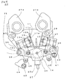
- Fig. 6 shows in section the structure of the cutting head 20 of Fig. 2 which is in the state in which the slide ring 22 is not locked by the lock mechanism 23.
- teeth around the outside of the slide ring 22 and around the inside of the lock mechanism 23 facing the slide ring 22, so that they are meshed with each other.
- Compressed springs 47, 48 are provided between the slide ring 22 and the pivoted cam 43 and between the slide ring 22 and the pivoted cam 44, respectively. These springs bias the pivoted cams 43, 44 so that cam surfaces of the pivoted cams 43, 44 at the side thereof can be brought into contact with the followers 45, 46.
- levers 49, 50 on the back side of the cutting blade 11. These levers 49, 50 are supported at base end portions thereof by the pivot shafts 51, 52 provided on the side of the knife guide 25, with spaced a short distance, so that they can be freely pivotally displaced. The front end portions of the levers 49, 50 sandwich a projecting portion 53 on the slide ring 22 between them. A tensile spring 54 is provided between the levers 49, 50 to bias the levers 49, 50 so that the front end portions of the levers 49, 50 can sandwich the projecting portion 53 between them. This action of the levers 49, 50 can allow the slide ring 22 to follow the rotary cylinder 21 turning, so that a displacement angle of the rotary cylinder 21 to the slide ring 22 can be kept at a reference angle of 0° .
- Fig. 7 shows the state in which the slide ring 22 is locked by the lock mechanism 23 and the rotary cylinder 21 is displaced with respect to the slide ring 22 in the clockwise direction of the drawing figure at only an angle of 14° .
- the slide ring 22 and the lock mechanism 23 are locked by engagement between the teeth provided around the outside of the slide ring 22 and around the inside of the lock mechanism 23, the reliable lock can be provided.
- the slide ring 22 locked is angularly displaced, as illustrated with the leg 21a up as in Fig. 6 .
- the follower 46 of the support block 14 is pressed rightwards of the drawing figure by the pivoted cam 44.
- the follower 45 is disengaged from the pivoted cam 43, so that it is not subjected to the action of the cam.
- the support block 14 supported by the four-joint link mechanism of Fig. 4 is moved rightwards of the drawing figure.
- Fig. 8 shows the relation between the whetstone holding mechanism 15 and the cutting blade 11 of Fig. 7 .
- the follower 46 is pressed rightwards by the pivoted cam 44, the flat surface 13b of the rotary whetstone 13 is brought into contact with the other side 11c of the cutting edge 11a of the cutting blade 11.
- This angle of the rotary cylinder 21 is set as a contact initiation angle.
- Fig. 9 shows the state in which the rotary cylinder 21 is in contact with the cutting blade 11 at an angle of 16° by being angularly changed further with respect to the slide ring 22 of Fig. 7 .
- resistance to the movement of the follower 46 becomes greater than a pressing force of the compressed spring 48 pressing the pivoted cam 44 shown in Fig. 6 and thereby the rightward movement of the flat surface 13b is brought to stop.
- the flat surface 13b is moved forward.
- the rotary cylinder 21 can be displaced relative to the slide ring 22 in the counterclockwise direction, to sharpen the cutting blade 11 with the rotary whetstone 12.
- the follower 45 can be pressed leftwards by the pivoted cam 43 to bring the rotary whetstone 12 into contact with the cutting blade 11.
- the use of the rotary whetstone 12 can also allow the sharpening of the cutting blade 11, as in the case of the use of the rotary whetstone 13.
- the whetstone holding mechanism 15 is supported by the legs 21 a at the bottom part of the rotary cylinder 21 in the embodiment illustrated above, since the construction is compact, the whetstone holding mechanism 15 may be properly arranged according to the construction of the cutting head 20, with less limitation on arrangement. While the whetstone holding mechanism 15 is supported by the four-joint link mechanism to allow the selective switch between the sharpening states by the turning of the R-axis, a power source, such as a motor, may be incorporated in the mechanism to move the whetstone holding mechanism automatically. While the rotary whetstones 12, 13 are also driven from outside of the rotation ring 24 through the rotation ring 24, the gear 33, and the timing belt 31, a power source, such as a motor, may be incorporated to drive the rotary whetstones.
- a power source such as a motor
- the rotary whetstones 12, 13 are used for sharpening the cutting blade 11, when the cutting blade 11 is sharpened while being moved, the cutting blade may be sharpened by simply being brought into contact with the stationary whetstones.
- the use of the rotary whetstones 12, 13 rotating can allow the speed-up of the sharpening to avoid reduction in production efficiency caused by the sharpening.
- a driving source such as a motor, may be provided in the rotary cylinder 21 to drive the rotary whetstones 12, 13.
- the cutting blade 11 has a reciprocating straight blade, even if the cutting blade 11 has a rotating round blade, the concept of the invention can be applied to at least one circumferential point, to sharpen both sides of the cutting edge of such a round blade in the same manner as in the sharpening of the cutting blade 11.
Landscapes
- Engineering & Computer Science (AREA)
- Mechanical Engineering (AREA)
- Life Sciences & Earth Sciences (AREA)
- Forests & Forestry (AREA)
- Finish Polishing, Edge Sharpening, And Grinding By Specific Grinding Devices (AREA)
- Control Of Cutting Processes (AREA)
Abstract
Description
- The present invention relates to a cutting machine for cutting a sheet material and the like, or particularly to a cutting machine having the function of sharpening a cutting blade.
- In general, when a sheet material such as textile fabric is shaped into sewing parts, the cutting is performed based on a paper pattern or on the data corresponding to the paper pattern. A cutting machine or the like used for the cutting has a sharpening function to keep sharpness of a cutting blade for cutting the sheet material (Cf.
Patent Citation 1, for example). The Patent Citation 1 discloses a sheet material cutting machine for cutting the sheet material with a cutting knife which is moved in reciprocation along a vertical axis line and also discloses two different ways of sharpening the cutting knife from both sides of its cutting edge. -
Fig. 10 shows those two different concepts on the sharpening disclosed by Patent Citation 1.Fig. 10(a) shows one concept on the sharpening with a rounded surface around the outside of a rotary whetstone disclosed in its Fig. 11 and the like.Fig. 10(b) shows another concept on sharpening with a flat surface of the rotary whetstone perpendicular to an axis thereof disclosed in its Fig. 13 and the like. In the following, the simplified construction is illustrated, for explanatory convenience. Although names and reference numerals of parts may vary, the correspondence relation to the two different concepts on the sharperning should be obvious. - In
Fig. 10(a) , one side 1b of the cutting edge 1a of thecutting knife 1 and the other side 1c of the same are ground with cylindrical surfaces 2a, 3a of outer peripheries of tworotary whetstones rotary whetstones support block 4. The two arms 4a, 4b are fixed with spaced apart from each other at a certain angle. Thesupport block 4 can be pivoted about or swung and displaced around apivot shaft 5 penetrating intermediate portion between the arms 4a, 4b. When thesupport block 4 is pivotally displaced with respect to thepivot shaft 5 in one direction or the other, the one side 1b of thecutting knife 1 or the other side 1c of the same can be ground with the related cylindrical surface 2a, 3a of therotary whetstone knife 1 initially have a linear cross-sectional shape, they are varied in cross-section to have a concave surface, as shown as a shaded area. - In
Fig. 10(b) , like reference numerals are labeled to corresponding parts toFig. 10(a) , to avoid redundant explanation. In thesupport block 4, the arms 4a, 4b mount therotary whetstones cutting knife 1, respectively. Although therotary whetstones cutting knife 1 in the full-line state, they can be switched to the state in which the flat surfaces 2b, 3b perpendicular to the rotation shafts are put in contact with the one side 1b and the other side 1c of theknife 1, respectively, to sharpen them. For example, when thesupport block 4 is pivotally displaced in one direction with respect to thepivot shaft 5, the flat surface 2b of therotary whetstone 2 is switched to the state of being put in contact with the one side 1b of thecutting knife 1 to sharpen it. Likewise, when thesupport block 4 is pivotally displaced in the other direction with respect to thepivot shaft 5, the flat surface 3b of therotary whetstone 3 is switched to the state of being put in contact with the other side 1c of thecutting knife 1 to sharpen it. As thecutting knife 1 is ground with the flat surfaces 2b, 3b, the linear cross-sectional shape of thecutting knife 1 is kept unchanged, as shown as the shaded area. - In the sharpening way shown in
Fig. 10(a) , the cylindrical surfaces 2a, 2b of therotary whetstones cutting knife 1 and the other side 1c of the same, respectively, via a link mechanism and the like, not via an overall pivotal displacement of the support block 4 (Cf.Patent Citation 2, for example). According to Patent Citation 2, therotary whetstones cutting knife 1. The switching between the sharpening states is performed by turning the rotary cylinder while locking the rotation ring mounted on the rotary cylinder to be stationary relative to outside. A relative angular displacement between the rotation ring stationary with respect to outside and the rotary cylinder able to turn with respect to outside allows the rotary whetstones to pivotally displaced separately via the cams and the link mechanism, thereby allowing the switching between the sharpening states. - Patent Citation 1:
JP Patent Publication No. Sho 56-8759 - Patent Citation 2:
JP Patent No. 3390219 -
Fig. 10(a) also shows that when being ground using the cylindrical surfaces 2a, 3a of therotary whetstones cutting knife 1 initially has a face of a curved cross-sectional shape, as shown as the shaded area. Even in this case, as the sharpening with the cylindrical surface 2a, 3a progresses, the decrease in thickness of the ground area on the side close to the cutting edge 1a becomes greater than on the shoulder side farthest from the cutting edge 1a and thus an angle of the cutting edge becomes greater. In either case, as long as the cutting knife is ground using the cylindrical surfaces 2a, 3a, the initial angle of the cutting edge cannot be kept unchanged. - As shown in
Fig. 10(b) , when the cutting knife is ground using the flat surfaces 2b, 3b of therotary whetstones pivot shaft 5, when the sharpening is repeated, both the one side 1b and the other side 1c vary in angle of inclination, so that the angle of the cutting edge decreases and the rigidity decreases. If it is assumed that an angular displacement of θ ° around thepivot shaft 5 is provided for the broken-line sharpening state of the one side 1b, then an angular displacement of - θ ° around thepivot shaft 5 is required for the sharpening state of the other side 1c. Where an angle of the cutting edge formed between the one side 1b and the other side 1c which are converged at the cutting edge 1a is set φ ° , it follows that an angle of the space between the flat surfaces 2b, 3b is 2 × θ ° + φ ° . This means that therotary whetstones support block 4, with their flat surfaces 2b, 3b spaced at an angle of 2 × θ ° + φ ° , and thesupport block 4 must be pivoted about thepivot shaft 5 at an angle of at least ± θ ° , thus requiring a large space. - If the arrangement for sharpening with the flat surfaces 2b, 3b requiring such a large space is supported by the rotary cylinder as is disclosed by Patent Citation 2, then the arrangement will be increased in size. Even if the sharpening with the flat surfaces 2b, 3b of the
rotary whetstones Patent Citation 2, since the angle at which the flat surfaces 2b, 3b are put in contact with the one side 1b and the other side 1c of the cutting edge 1c by the pivotal displacement varies with the progress of the sharpening, such modification cannot provide the sharpening in such a manner as to keep the angle of the cutting edge unchanged. - It is an object of the present invention to provide a cutting machine capable of sharpening in such a manner as to keep an angle of the cutting edge constant.
- The present invention provides a cutting machine for cutting a sheet material to be cut, which is put on a cutting table, with a cutting blade provided in a cutting head movable along the cutting table,
wherein the cutting blade is used while both sides of its cutting edge are ground to keep sharpness of the cutting edge, and
the cutting head is provided with: - a one side use abrasive whetstone for sharpening one side of the cutting edge of the cutting blade with its flat surface,
- an other side use abrasive whetstone for sharpening the other side of the cutting edge of the cutting blade with its flat surface, and
- a whetstone holding mechanism that can allow selective switch between a standby state in which the one side use abrasive whetstone and the other side use abrasive whetstone are away from any of the one side of the cutting edge and the other side of the same, while the flat surface of the one side use abrasive whetstone and that of the other side use abrasive whetstone are kept in parallel with the one side of the cutting blade and the other side of the same, respectively, and an one side sharpening state in which the one side use abrasive whetstone is put in contact with the one side of the cutting edge or an other side sharpening state in which the other side use abrasive whetstone is put in contact with the other side of the cutting edge.
- In the cutting machine according to the present invention,
said cutting head comprises: - a rotary cylinder containing the cutting blade and being capable of turning around a rotation shaft of the cutting edge perpendicular to a surface of the cutting table, to change a cutting direction of the cutting blade;
- a slide ring provided on a peripheral side of the rotary cylinder so that it can follow the rotary cylinder turning in a turning direction; and
- a lock mechanism provided at a radial outside of the rotary cylinder so that it can lock the slide ring to the cutting head;
- said whetstone holding mechanism is provided in the rotary cylinder to allow the selective switch between the standby state, and the one side sharpening state or the other side sharpening state according to a turning angle of the rotary cylinder around the rotation shaft of the cutting edge when the slide ring is locked by the lock mechanism.
- In the cutting machine according to the present invention,
said whetstone holding mechanism is supported in spaced relation on front ends of a pair of swing arms which are supported capable with swing displacement at base end portions thereof on a pair of pivot shafts which are arranged in the rotary cylinder in standing relation, with spaced, at both sides of the cutting edge of the cutting blade and are parallel with the rotation shaft of the cutting edge, and
said slide ring is provided with cams for guiding the whetstone holding mechanism to positions corresponding to the standby state, the one side sharpening state, and the other side sharpening state, respectively. - In the cutting machine according to the present invention,
said rotary cylinder is provided with a rotation ring which can be rotationally driven from outside and has an internal tooth around an inside thereof,
said whetstone holding mechanism is equipped with a gear to engage with the internal tooth of the rotation ring,
said cams are formed to guide the whetstone holding mechanism in such a manner as to change a position of the whetstone holding mechanism while keeping the engagement between the gear and the internal tooth of the rotation ring, and
said one side use abrasive whetstone and said other side use abrasive whetstone are rotated by a rotational driving force transmitted from outside of the rotary cylinder to the gear through the rotation ring, to sharpen the cutting blade. - According to the present invention, since the flat abrasive surface of the one side use abrasive whetstone and the flat abrasive surface of the other side use abrasive whetstone are kept in parallel with the one side of the cutting blade and the other side of the same, respectively, by the whetstone holding mechanism provided in the cutting head, the sharpening can be carried out in such a manner as to keep an angle of the cutting edge constant.
- According to the present invention, the cutting blade sharpening elements are contained in the rotary cylinder able to turn around the rotation shaft of the cutting edge, and the selective switch between the sharpening states can be made at an angle of rotation of the rotary cylinder in the state in which the slide ring is locked by the lock mechanism.
- According to the present invention, since the whetstone holding mechanism is supported in spaced relation on front ends of a pair of swing arms which are supported capable with swing displacement at base end portions thereof to the rotary cylinder in spaced relation, a four-joint link mechanism is formed, respective sides of which are formed by the rotary cylinder, the pair of swing arms, and the whetstone holding mechanism. Since the front end portions of the swing arms are guided via this four-joint link mechanism, the mechanism for moving the one side use abrasive whetstone and the other side use abrasive whetstone, which are held by the whetstone holding mechanism, while keeping the state in which an angle formed between the both flat surfaces used for the sharpening corresponds to an angle of the cutting edge, can be made compact.
- According to the present invention, the one side use abrasive whetstone and the other side use abrasive whetstone can be rotationally driven from outside of the rotary cylinder.
-
- [
Fig.1] Fig. 1 shows a partially sectioned plan view of a cuttingmachine 10 of an embodiment of the present invention, simplistically showing a construction for sharpening acutting blade 11. - [
Fig.2] Fig. 2 shows a front sectional view showing a schematic construction of a cuttinghead 20 used in the cuttingmachine 10 ofFig. 1 . - [
Fig.3] Fig. 3 shows a front view and a left side view showing a construction of awhetstone holding mechanism 15 ofFig. 2 . - [
Fig.4] Fig. 4 shows a front view showing acutting blade 11 sharpening construction ofFig. 2 from which a pivotedarm 37 and some other parts are omitted. - [
Fig.5] Fig. 5 shows a partial plan view of thewhetstone holding mechanism 15 and thecutting blade 11 ofFig. 2 which are in the standby state for sharpening and also shows a positional relation between four joints of a link system for supporting thewhetstone holding mechanism 15. - [
Fig.6] Fig. 6 shows a plane section view showing the construction of the cuttinghead 20 ofFig. 2 which is in the state in which aslide ring 22 is not locked by alock mechanism 23. - [
Fig.7] Fig. 7 shows a plane section view showing the construction of the cuttinghead 20 ofFig. 2 which is in the state in which theslide ring 22 is not locked by thelock mechanism 23. - [
Fig.8] Fig. 8 shows a partially sectioned plan view showing the relation between thewhetstone holding mechanism 15 and thecutting blade 11 ofFig. 6 . - [
Fig. 9] Fig. 9 shows a partially sectioned plan view showing the state in which arotary cylinder 21 is in contact with thecutting blade 11 at an angle of 16° by being angularly changed further with respect to theslide ring 22 ofFig. 7 . - [
Fig. 10] Fig. 10 shows sectional views showing simplified illustrations of two different known concepts on the sharpening of the cutting edge. -
- 10
- Cutting machine
- 11
- Cutting blade
- 11a
- Cutting edge
- 11b
- One side
- 11c
- Other side
- 12, 13
- Rotary whetstone
- 12b, 13b
- Flat surface
- 14
- Support block
- 15
- Whetstone holding mechanism
- 20
- Cutting head
- 21
- Rotary cylinder
- 21a
- Leg
- 22
- Slide ring
- 23
- Lock mechanism
- 24
- Rotation ring
- 25
- Knife guide
- 28
- Support frame
- 33
- Gear
- 35,36
- Support shaft
- 37,38
- Swing arm
- 39, 40, 41, 42, 51, 52
- Pivot shaft
- 43, 44
- Pivoted cam
- 45, 46
- Follower
- 49, 50
- Lever
- 53
- Projecting portion
-
Fig. 1 shows a cuttingmachine 10 of an embodiment of the present invention, simplistically showing a construction for sharpening acutting blade 11. Thecutting blade 11 has a cutting edge 11a formed by one slant side surface 11b and the other slant side surface 11c being joined together at their tips and has a pentagonal cross-sectional shape. Thecutting blade 11 is driven to move in reciprocation in a direction perpendicular to paper and can cut a sheet material to a direction for the cutting edge 11a to point. A cutting head including a mechanism to support and drive the cuttingblade 11 is moved in parallel with and over a cutting table on which the sheet material is carried so that the sheet material can be cut with the cutting edge 11a shifted in position or changed in direction to point. - The cutting head is provided therein with a
whetstone holding mechanism 15, placed in front of the cutting edge 11a of thecutting blade 11, for holding a pair ofrotary whetstones support block 14. Thesupport block 14 is provided with two arms 14a, 14b spaced at a certain angle, and rotation shafts 12a, 13a of therotary whetstones rotary whetstones cutting blade 11, respectively. Thewhetstone holding mechanism 15 can move in parallel linearly or can swing almost linearly, as mainly indicated by Arrow 15a, to bring the flat surface 12b of therotary whetstone 12 into contact with the one side 11b of thecutting blade 11, as depicted by a broken line, thereby switching to the sharpening state. Likewise, when the other side 11c of thecutting blade 11 is ground with the flat surface 13b of therotary whetstone 13, thewhetstone holding mechanism 15 can move while keeping the one side 11b or the other side 11c of the cutting edge 11a of thecutting blade 11 in parallel with the flat surface 12b, 13b of therotary whetstone -
Fig. 2 shows a schematic construction of the cuttinghead 20 used in the cuttingmachine 10 ofFig. 1 . The cuttinghead 20 includes the drive mechanism, placed over thecutting blade 11, for driving thecutting blade 11 in reciprocation, though omitting illustration. The turning of arotary cylinder 21 allows thecutting blade 11 to turn around the R-axis as a cutting edge turning axis, to change the direction of cutting. Aslide ring 22 is provided under therotary cylinder 21, and alock mechanism 23 is provided at the outside of theslide ring 22 so that theslide ring 22 can be locked to outside. When being not locked by thelock mechanism 23, theslide ring 22 follows therotary cylinder 21 turning. To allow the selective switch between the sharpening states by thewhetstone holding mechanism 15 as shown inFig. 1 , theslide ring 22 is locked by thelock mechanism 23 so that only therotary cylinder 21 is turned. - There is provided a
rotation ring 24 over theslide ring 22 and under therotary cylinder 21. Therotary cylinder 21 has legs 21 a extending downwards through theslide ring 22 and supporting aknife guide 25 thereon. Theknife guide 25 supports thecutting blade 11 so that thecutting blade 11 can be prevented from being deformed or displaced when moved vertically. The legs 21a support afoot presser 26 at lower ends thereof. Thefoot presser 26 is to be put on the sheet material to be cut and the like. Thewhetstone holding mechanism 15 is supported at a position opposed to theknife guide 25 via a front end portion of aswing arm 37 and the like, as mentioned later. Theswing arm 37 is supported at a base end thereof by the leg 21a to be freely pivoted. Thewhetstone holding mechanism 15 includes a cutting edgeposition detecting mechanism 27 for detecting a position of the cutting edge 11a of thecutting blade 11 and also detecting wear of thecutting blade 11 caused by the sharpening and the cutting of thecutting blade 11. Therotary cylinder 21 is supported by asupport frame 28 of the cuttinghead 20 to be freely rotatable via abearing 29. Thelock mechanism 23 locks so that theslide ring 24 can be made stationary with respect to thesupport frame 28. Therotary cylinder 21 mounts thereon a pulley 21b to receive a rotational driving force from outside. Therotation ring 24 is supported to therotary cylinder 21 via abearing 30. A timing belt is wound around therotation ring 24 to receive the rotational driving force to rotate therotary whetstone gear 33 meshed with an internally-toothed gear. The details on thegear 33, a slide ring pivoted cam 43, a follower 45, alever 49, and a pivot shaft 51 are described later. -
Fig. 3 shows the construction of thewhetstone holding mechanism 15 ofFig. 2 .Fig. 3(a) shows the construction as viewed from the left side ofFig. 2 andFig. 3(b) shows the construction as viewed from the front side ofFig. 2 . Therotary whetstones rotary whetstone 12 is provided at a base portion thereof with a pulley 12a, around which atiming belt 31 is wound. Therotary whetstone 13 is also provided with a pulley 13c, as mentioned later. Thesingle timing belt 31 in total runs around therotary whetstones drive shaft 34 mounting thegear 33 on an upper end thereof. The lower pulley 32b rotates freely. Thesupport block 14 is provided withsupport shafts -
Fig. 4 shows the construction of sharpening thecutting blade 11 ofFig. 3 from which aswing arm 37 and some other parts are omitted. Theknife guide 25 has a shape not to contact with therotary whetstone 12 at the position where thecutting blade 11 is sharpened. At the time of sharpening, thecutting blade 11 is moved vertically a stroke so that it can be uniformly sharpened in the longitudinal direction. One end of atension spring 54 mentioned later is fixed to thelever 49. -
Fig. 5 shows thewhetstone holding mechanism 15 and thecutting blade 11 ofFig. 2 which are in the standby state for sharpening. Each of the following drawing figures shows the construction of therotary cylinder 21 as viewed from below the downwardly extending legs 21a.Fig. 5(a) shows the construction in which thewhetstone holding mechanism 15 is supported via a link mechanism.Fig. 5(b) shows a positional relation between four joints of the link mechanism for supporting thewhetstone holding mechanism 15. The pair ofswing arms support shafts Fig. 3(a) , to freely pivot about them. Theswing arms pivot shafts rotary cylinder 21 so that they can be freely pivotally displaced. The pivotedcams 43, 44 are supported by pivot shafts 41, 42 supported by theslide ring 22, so that they can be freely pivotally displaced. The pivoted cam 43 is biased in a counterclockwise direction and the pivotedcam 44 is biased in a clockwise direction by respective springs, so that their cam surfaces are respectively put in contact with followers 45, 46 provided in thesupport block 14. In the standby state as illustrated, a tip of a pin 27a of the cutting edgeposition detecting mechanism 27 confronts the cutting edge 11a of thecutting blade 11. By pressing the pin 27a to detect the position of the tip of the pin 27a to abut with the cutting edge 11a, the position of the cutting edge 11a can be detected. As the process of sharpening progresses, this position of the cutting edge 11a gradually goes back. - The
rotary whetstones rotary whetstones timing belt 31 is wound are mounted to the rotation shafts 12a, 13a at the base side of therotary whetstones - As shown in
FIG. 5(b) , the pair ofswing arms pivot shafts support shafts drive shaft 34 of thegear 33 is also set to be on the arc drawn with the same radius R, thegear 33 can be moved so that itspitch circle 33p is always in contact with a pitch circle 24p of the internal teeth of therotation ring 24. Thesupport block 14 of thewhetstone holding mechanism 15 is supported via the four-joint link structure with the centers of thepivot shafts support shafts arms arms 43, 44. When the position of the third joint of the four-joint link is determined, the position of the other of the followers 45, 46, which serves as the fourth joint, is determined automatically. By guiding the followers 45, 46 properly by the pivotedcams 43, 44, the flat surfaces 12b, 13b of therotary whetstones support block 14 can be pivoted in a nearly parallel displacement. When an internal tooth is provided around the inside of therotation ring 24 shown inFIG. 2 and is meshed with thegear 33, the rotational driving force applied from outside can be transmitted to thegear 33 through therotation ring 24 and thus therotary whetstones -
Fig. 6 shows in section the structure of the cuttinghead 20 ofFig. 2 which is in the state in which theslide ring 22 is not locked by thelock mechanism 23. There are provided teeth around the outside of theslide ring 22 and around the inside of thelock mechanism 23 facing theslide ring 22, so that they are meshed with each other.Compressed springs 47, 48 are provided between theslide ring 22 and the pivoted cam 43 and between theslide ring 22 and the pivotedcam 44, respectively. These springs bias the pivotedcams 43, 44 so that cam surfaces of the pivotedcams 43, 44 at the side thereof can be brought into contact with the followers 45, 46. - There are provided a pair of
levers cutting blade 11. Theselevers knife guide 25, with spaced a short distance, so that they can be freely pivotally displaced. The front end portions of thelevers portion 53 on theslide ring 22 between them. Atensile spring 54 is provided between thelevers levers levers portion 53 between them. This action of thelevers slide ring 22 to follow therotary cylinder 21 turning, so that a displacement angle of therotary cylinder 21 to theslide ring 22 can be kept at a reference angle of 0° . -
Fig. 7 shows the state in which theslide ring 22 is locked by thelock mechanism 23 and therotary cylinder 21 is displaced with respect to theslide ring 22 in the clockwise direction of the drawing figure at only an angle of 14° . As described above, since theslide ring 22 and thelock mechanism 23 are locked by engagement between the teeth provided around the outside of theslide ring 22 and around the inside of thelock mechanism 23, the reliable lock can be provided. For the explanatory convenience, theslide ring 22 locked is angularly displaced, as illustrated with the leg 21a up as inFig. 6 . The follower 46 of thesupport block 14 is pressed rightwards of the drawing figure by the pivotedcam 44. The follower 45 is disengaged from the pivoted cam 43, so that it is not subjected to the action of the cam. Thesupport block 14 supported by the four-joint link mechanism ofFig. 4 is moved rightwards of the drawing figure. -
Fig. 8 shows the relation between thewhetstone holding mechanism 15 and thecutting blade 11 ofFig. 7 . When the follower 46 is pressed rightwards by the pivotedcam 44, the flat surface 13b of therotary whetstone 13 is brought into contact with the other side 11c of the cutting edge 11a of thecutting blade 11. This angle of therotary cylinder 21 is set as a contact initiation angle. -
Fig. 9 shows the state in which therotary cylinder 21 is in contact with thecutting blade 11 at an angle of 16° by being angularly changed further with respect to theslide ring 22 ofFig. 7 . In this regard, when the flat surface 13b of therotary whetstone 13 is put in contact with thecutting blade 11, resistance to the movement of the follower 46 becomes greater than a pressing force of the compressed spring 48 pressing the pivotedcam 44 shown inFig. 6 and thereby the rightward movement of the flat surface 13b is brought to stop. As thecutting blade 11 is worn by the sharpening, the flat surface 13b is moved forward. - Different from
Figs. 6-7 , therotary cylinder 21 can be displaced relative to theslide ring 22 in the counterclockwise direction, to sharpen thecutting blade 11 with therotary whetstone 12. In thesupport block 14 of thewhetstone holding mechanism 15, the follower 45 can be pressed leftwards by the pivoted cam 43 to bring therotary whetstone 12 into contact with thecutting blade 11. Thus, the use of therotary whetstone 12 can also allow the sharpening of thecutting blade 11, as in the case of the use of therotary whetstone 13. - Although the
whetstone holding mechanism 15 is supported by the legs 21 a at the bottom part of therotary cylinder 21 in the embodiment illustrated above, since the construction is compact, thewhetstone holding mechanism 15 may be properly arranged according to the construction of the cuttinghead 20, with less limitation on arrangement. While thewhetstone holding mechanism 15 is supported by the four-joint link mechanism to allow the selective switch between the sharpening states by the turning of the R-axis, a power source, such as a motor, may be incorporated in the mechanism to move the whetstone holding mechanism automatically. While therotary whetstones rotation ring 24 through therotation ring 24, thegear 33, and thetiming belt 31, a power source, such as a motor, may be incorporated to drive the rotary whetstones. - Although the
rotary whetstones cutting blade 11, when thecutting blade 11 is sharpened while being moved, the cutting blade may be sharpened by simply being brought into contact with the stationary whetstones. The use of therotary whetstones rotary cylinder 21 to drive therotary whetstones cutting blade 11 has a reciprocating straight blade, even if thecutting blade 11 has a rotating round blade, the concept of the invention can be applied to at least one circumferential point, to sharpen both sides of the cutting edge of such a round blade in the same manner as in the sharpening of thecutting blade 11.
Claims (4)
- A cutting machine for cutting a sheet material to be cut, which is put on a cutting table, with a cutting blade provided in a cutting head movable along the cutting table,
wherein the cutting blade is used while both sides of its cutting edge are ground to keep sharpness of the cutting edge, and
the cutting head is provided with:a one side use abrasive whetstone for sharpening one side of the cutting edge of the cutting blade with its flat surface,an other side use abrasive whetstone for sharpening the other side of the cutting edge of the cutting blade with its flat surface, anda whetstone holding mechanism that can allow selective switch between a standby state in which the one side use abrasive whetstone and the other side use abrasive whetstone are away from any of the one side of the cutting edge and the other side of the same, while the flat surface of the one side use abrasive whetstone and that of the other side use abrasive whetstone are kept in parallel with the one side of the cutting blade and the other side of the same, respectively, and an one side sharpening state in which the one side use abrasive whetstone is put in contact with the one side of the cutting edge or an other side sharpening state in which the other side use abrasive whetstone is put in contact with the other side of the cutting edge. - The cutting machine according to claim 1,
wherein said cutting head comprises:a rotary cylinder containing the cutting blade and being capable of turning around a rotation shaft of the cutting edge perpendicular to a surface of the cutting table, to change a cutting direction of the cutting blade;a slide ring provided on a peripheral side of the rotary cylinder so that it can follow the rotary cylinder turning in a turning direction; anda lock mechanism provided at a radial outside of the rotary cylinder so that it can lock the slide ring to the cutting head;said whetstone holding mechanism is provided in the rotary cylinder to allow the selective switch between the standby state, and the one side sharpening state or the other side sharpening state according to a turning angle of the rotary cylinder around the rotation shaft of the cutting edge when the slide ring is locked by the lock mechanism. - The cutting machine according to claim 2,
wherein said whetstone holding mechanism is supported in spaced relation on front ends of a pair of swing arms which are supported capable with swing displacement at base end portions thereof on a pair of pivot shafts which are arranged in the rotary cylinder in standing relation, with spaced, at both sides of the cutting edge of the cutting blade and are parallel with the rotation shaft of the cutting edge, and
said slide ring is provided with cams for guiding the whetstone holding mechanism to positions corresponding to the standby state, the one side sharpening state, and the other side sharpening state, respectively. - The cutting machine according to claim 3,
wherein said rotary cylinder is provided with a rotation ring which can be rotationally driven from outside and has an internal tooth around an inside thereof,
said whetstone holding mechanism is equipped with a gear to engage with the internal tooth of the rotation ring,
said cams are formed to guide the whetstone holding mechanism in such a manner as to change a position of the whetstone holding mechanism while keeping the engagement between the gear and the internal tooth of the rotation ring, and
said one side use abrasive whetstone and said other side use abrasive whetstone are rotated by a rotational driving force transmitted from outside of the rotary cylinder to the gear through the rotation ring, to sharpen the cutting blade.
Applications Claiming Priority (2)
| Application Number | Priority Date | Filing Date | Title |
|---|---|---|---|
| JP2007248275 | 2007-09-25 | ||
| PCT/JP2008/002629 WO2009041021A1 (en) | 2007-09-25 | 2008-09-24 | Cutting machine |
Publications (3)
| Publication Number | Publication Date |
|---|---|
| EP2196294A1 true EP2196294A1 (en) | 2010-06-16 |
| EP2196294A4 EP2196294A4 (en) | 2012-11-21 |
| EP2196294B1 EP2196294B1 (en) | 2014-07-09 |
Family
ID=40510928
Family Applications (1)
| Application Number | Title | Priority Date | Filing Date |
|---|---|---|---|
| EP08833404.0A Not-in-force EP2196294B1 (en) | 2007-09-25 | 2008-09-24 | Cutting machine |
Country Status (5)
| Country | Link |
|---|---|
| US (1) | US8216029B2 (en) |
| EP (1) | EP2196294B1 (en) |
| JP (1) | JP5015257B2 (en) |
| CN (1) | CN101808785B (en) |
| WO (1) | WO2009041021A1 (en) |
Cited By (2)
| Publication number | Priority date | Publication date | Assignee | Title |
|---|---|---|---|---|
| US9597764B2 (en) | 2013-09-09 | 2017-03-21 | Universal Tissue Technology | Cutting machine with grinding unit |
| IT201700081306A1 (en) * | 2017-07-18 | 2019-01-18 | Perini Fabio Spa | SHARPENING UNIT FOR A CUTTING BLADE, MACHINE INCLUDING SUCH GROUP AND METHOD |
Families Citing this family (10)
| Publication number | Priority date | Publication date | Assignee | Title |
|---|---|---|---|---|
| US8944894B2 (en) * | 2012-10-25 | 2015-02-03 | Smith's Consumer Products, Inc. | Adjustable abrasive sharpener |
| CN104168993B (en) | 2012-03-16 | 2016-07-06 | 通用电气健康护理生物科学股份公司 | Hybrid system |
| CN103776360B (en) * | 2012-10-24 | 2017-06-06 | 绵阳市维博电子有限责任公司 | An automatic cutting machine cutting knife deformation detection device |
| CN104097119A (en) * | 2013-04-15 | 2014-10-15 | 上海和鹰机电科技股份有限公司 | Automatic cutter sharpening control system for cloth paving machine |
| US9469014B2 (en) * | 2013-11-26 | 2016-10-18 | Wolff Industries, Inc. | Conditioning device for conditioning a blade |
| CN106835667B (en) * | 2016-12-30 | 2019-04-16 | 开平市红日制衣有限公司 | A cloth cutting machine capable of grinding cloth cutting knives |
| CN107825231A (en) * | 2017-09-08 | 2018-03-23 | 广东拓荒牛智能切割科技股份有限公司 | A kind of cut-off knife head sharpening system |
| CN107414612B (en) * | 2017-09-11 | 2025-01-28 | 合肥奥瑞数控科技有限公司 | Knife sharpening device for cloth cutting machine |
| CN110370345B (en) * | 2019-07-30 | 2020-05-12 | 温州宏量机械科技有限公司 | Cutting machine with automatic sharpening mechanism |
| JP7776404B2 (en) * | 2022-11-28 | 2025-11-26 | 株式会社島精機製作所 | Method for obtaining wear level of cutting machine and cutting blade |
Family Cites Families (7)
| Publication number | Priority date | Publication date | Assignee | Title |
|---|---|---|---|---|
| US4033214A (en) * | 1973-09-17 | 1977-07-05 | Gerber Garment Technology, Inc. | Blade sharpener |
| US4732064A (en) * | 1987-03-05 | 1988-03-22 | Gerber Garment Technology, Inc. | Apparatus and method for sharpening edges of reciprocating blade |
| JP3390219B2 (en) * | 1993-08-20 | 2003-03-24 | 株式会社島精機製作所 | Cutting blade polishing device |
| JPH0822520B2 (en) * | 1993-11-19 | 1996-03-06 | 株式会社島精機製作所 | Apparatus and method for controlling cutting amount of cutting blade |
| JP3164496B2 (en) * | 1995-10-09 | 2001-05-08 | 株式会社島精機製作所 | Cutting machine |
| JP4259044B2 (en) * | 2002-06-14 | 2009-04-30 | 株式会社村田製作所 | Cutting blade and blade surface machining method |
| CN1729367B (en) * | 2002-12-20 | 2010-05-26 | 株式会社岛精机制作所 | Vibration damping device and cutting head for reciprocating drive |
-
2008
- 2008-09-24 CN CN2008801085423A patent/CN101808785B/en not_active Expired - Fee Related
- 2008-09-24 JP JP2009534171A patent/JP5015257B2/en not_active Expired - Fee Related
- 2008-09-24 EP EP08833404.0A patent/EP2196294B1/en not_active Not-in-force
- 2008-09-24 US US12/679,767 patent/US8216029B2/en not_active Expired - Fee Related
- 2008-09-24 WO PCT/JP2008/002629 patent/WO2009041021A1/en not_active Ceased
Cited By (4)
| Publication number | Priority date | Publication date | Assignee | Title |
|---|---|---|---|---|
| US9597764B2 (en) | 2013-09-09 | 2017-03-21 | Universal Tissue Technology | Cutting machine with grinding unit |
| IT201700081306A1 (en) * | 2017-07-18 | 2019-01-18 | Perini Fabio Spa | SHARPENING UNIT FOR A CUTTING BLADE, MACHINE INCLUDING SUCH GROUP AND METHOD |
| WO2019016666A1 (en) * | 2017-07-18 | 2019-01-24 | Fabio Perini S.P.A. | Grinding unit for a cutting blade, machine comprising said unit and related method |
| US12011798B2 (en) | 2017-07-18 | 2024-06-18 | Fabio Perini S.P.A. | Grinding unit for a cutting blade, machine comprising said unit and related method |
Also Published As
| Publication number | Publication date |
|---|---|
| US20100199826A1 (en) | 2010-08-12 |
| CN101808785B (en) | 2012-05-30 |
| EP2196294B1 (en) | 2014-07-09 |
| JP5015257B2 (en) | 2012-08-29 |
| JPWO2009041021A1 (en) | 2011-01-13 |
| EP2196294A4 (en) | 2012-11-21 |
| WO2009041021A1 (en) | 2009-04-02 |
| US8216029B2 (en) | 2012-07-10 |
| CN101808785A (en) | 2010-08-18 |
Similar Documents
| Publication | Publication Date | Title |
|---|---|---|
| EP2196294B1 (en) | Cutting machine | |
| EP2239111B1 (en) | Cutting machine | |
| US4732064A (en) | Apparatus and method for sharpening edges of reciprocating blade | |
| CN101284320B (en) | Reciprocating cutting tool | |
| FR2652029A1 (en) | METHOD AND DEVICE FOR AUTOMATIC SHARPENING OF CUTTING BLADES SUCH AS THOSE USED IN AUTOMATIC CUTTING MACHINES. | |
| CN103031671A (en) | Sewing machine | |
| US6644154B2 (en) | Apparatus for transverse cutting | |
| EA014573B1 (en) | Block-cutting gangsaw for cutting granite or other hard materials, and corresponding cutting method | |
| CN101374642B (en) | Grinding device for cutting knife of automatic cutting device | |
| CN201076947Y (en) | Reciprocal cutting tool and jig saw | |
| JP2602464B2 (en) | Blade polishing mechanism of cloth cutting device | |
| JP2018094675A (en) | Disk blade grinder | |
| JP7776404B2 (en) | Method for obtaining wear level of cutting machine and cutting blade | |
| JP2000108006A (en) | Belt exchange mechanism of belt type polishing machine | |
| JP3902432B2 (en) | XY table drive mechanism | |
| JPH06155372A (en) | Sheet material cutter | |
| JP5142567B2 (en) | Sewing machine cloth feeder | |
| KR200224104Y1 (en) | Saw blade cutting machine | |
| TWI279285B (en) | Reciprocation and tracking correction device for broad-banded sanding machine | |
| JPH1080851A (en) | Copy processing equipment | |
| WO2005025819A1 (en) | Cutting machine | |
| JPH03196996A (en) | Paper cutter | |
| JPS6359997A (en) | Press device | |
| JP2009172714A (en) | Cutting device for corrugated fin | |
| JP2007216323A (en) | Slide mechanism of tape wrap device |
Legal Events
| Date | Code | Title | Description |
|---|---|---|---|
| PUAI | Public reference made under article 153(3) epc to a published international application that has entered the european phase |
Free format text: ORIGINAL CODE: 0009012 |
|
| 17P | Request for examination filed |
Effective date: 20100331 |
|
| AK | Designated contracting states |
Kind code of ref document: A1 Designated state(s): AT BE BG CH CY CZ DE DK EE ES FI FR GB GR HR HU IE IS IT LI LT LU LV MC MT NL NO PL PT RO SE SI SK TR |
|
| AX | Request for extension of the european patent |
Extension state: AL BA MK RS |
|
| DAX | Request for extension of the european patent (deleted) | ||
| A4 | Supplementary search report drawn up and despatched |
Effective date: 20121024 |
|
| RIC1 | Information provided on ipc code assigned before grant |
Ipc: B26D 7/12 20060101AFI20121019BHEP Ipc: B26D 5/00 20060101ALI20121019BHEP Ipc: B24B 3/36 20060101ALI20121019BHEP |
|
| 17Q | First examination report despatched |
Effective date: 20130418 |
|
| RIC1 | Information provided on ipc code assigned before grant |
Ipc: B24B 3/36 20060101ALI20131129BHEP Ipc: B26D 7/12 20060101AFI20131129BHEP Ipc: B26D 5/00 20060101ALI20131129BHEP Ipc: B26F 1/38 20060101ALI20131129BHEP |
|
| GRAP | Despatch of communication of intention to grant a patent |
Free format text: ORIGINAL CODE: EPIDOSNIGR1 |
|
| INTG | Intention to grant announced |
Effective date: 20140116 |
|
| GRAS | Grant fee paid |
Free format text: ORIGINAL CODE: EPIDOSNIGR3 |
|
| GRAA | (expected) grant |
Free format text: ORIGINAL CODE: 0009210 |
|
| AK | Designated contracting states |
Kind code of ref document: B1 Designated state(s): AT BE BG CH CY CZ DE DK EE ES FI FR GB GR HR HU IE IS IT LI LT LU LV MC MT NL NO PL PT RO SE SI SK TR |
|
| REG | Reference to a national code |
Ref country code: GB Ref legal event code: FG4D |
|
| REG | Reference to a national code |
Ref country code: CH Ref legal event code: EP Ref country code: AT Ref legal event code: REF Ref document number: 676403 Country of ref document: AT Kind code of ref document: T Effective date: 20140715 |
|
| REG | Reference to a national code |
Ref country code: IE Ref legal event code: FG4D |
|
| REG | Reference to a national code |
Ref country code: DE Ref legal event code: R096 Ref document number: 602008033227 Country of ref document: DE Effective date: 20140821 |
|
| REG | Reference to a national code |
Ref country code: AT Ref legal event code: MK05 Ref document number: 676403 Country of ref document: AT Kind code of ref document: T Effective date: 20140709 |
|
| REG | Reference to a national code |
Ref country code: NL Ref legal event code: VDEP Effective date: 20140709 |
|
| REG | Reference to a national code |
Ref country code: LT Ref legal event code: MG4D |
|
| PG25 | Lapsed in a contracting state [announced via postgrant information from national office to epo] |
Ref country code: BG Free format text: LAPSE BECAUSE OF FAILURE TO SUBMIT A TRANSLATION OF THE DESCRIPTION OR TO PAY THE FEE WITHIN THE PRESCRIBED TIME-LIMIT Effective date: 20141009 Ref country code: FI Free format text: LAPSE BECAUSE OF FAILURE TO SUBMIT A TRANSLATION OF THE DESCRIPTION OR TO PAY THE FEE WITHIN THE PRESCRIBED TIME-LIMIT Effective date: 20140709 Ref country code: LT Free format text: LAPSE BECAUSE OF FAILURE TO SUBMIT A TRANSLATION OF THE DESCRIPTION OR TO PAY THE FEE WITHIN THE PRESCRIBED TIME-LIMIT Effective date: 20140709 Ref country code: SE Free format text: LAPSE BECAUSE OF FAILURE TO SUBMIT A TRANSLATION OF THE DESCRIPTION OR TO PAY THE FEE WITHIN THE PRESCRIBED TIME-LIMIT Effective date: 20140709 Ref country code: GR Free format text: LAPSE BECAUSE OF FAILURE TO SUBMIT A TRANSLATION OF THE DESCRIPTION OR TO PAY THE FEE WITHIN THE PRESCRIBED TIME-LIMIT Effective date: 20141010 Ref country code: PT Free format text: LAPSE BECAUSE OF FAILURE TO SUBMIT A TRANSLATION OF THE DESCRIPTION OR TO PAY THE FEE WITHIN THE PRESCRIBED TIME-LIMIT Effective date: 20141110 Ref country code: NO Free format text: LAPSE BECAUSE OF FAILURE TO SUBMIT A TRANSLATION OF THE DESCRIPTION OR TO PAY THE FEE WITHIN THE PRESCRIBED TIME-LIMIT Effective date: 20141009 Ref country code: ES Free format text: LAPSE BECAUSE OF FAILURE TO SUBMIT A TRANSLATION OF THE DESCRIPTION OR TO PAY THE FEE WITHIN THE PRESCRIBED TIME-LIMIT Effective date: 20140709 |
|
| PG25 | Lapsed in a contracting state [announced via postgrant information from national office to epo] |
Ref country code: IS Free format text: LAPSE BECAUSE OF FAILURE TO SUBMIT A TRANSLATION OF THE DESCRIPTION OR TO PAY THE FEE WITHIN THE PRESCRIBED TIME-LIMIT Effective date: 20141109 Ref country code: LV Free format text: LAPSE BECAUSE OF FAILURE TO SUBMIT A TRANSLATION OF THE DESCRIPTION OR TO PAY THE FEE WITHIN THE PRESCRIBED TIME-LIMIT Effective date: 20140709 Ref country code: NL Free format text: LAPSE BECAUSE OF FAILURE TO SUBMIT A TRANSLATION OF THE DESCRIPTION OR TO PAY THE FEE WITHIN THE PRESCRIBED TIME-LIMIT Effective date: 20140709 Ref country code: PL Free format text: LAPSE BECAUSE OF FAILURE TO SUBMIT A TRANSLATION OF THE DESCRIPTION OR TO PAY THE FEE WITHIN THE PRESCRIBED TIME-LIMIT Effective date: 20140709 Ref country code: CY Free format text: LAPSE BECAUSE OF FAILURE TO SUBMIT A TRANSLATION OF THE DESCRIPTION OR TO PAY THE FEE WITHIN THE PRESCRIBED TIME-LIMIT Effective date: 20140709 Ref country code: HR Free format text: LAPSE BECAUSE OF FAILURE TO SUBMIT A TRANSLATION OF THE DESCRIPTION OR TO PAY THE FEE WITHIN THE PRESCRIBED TIME-LIMIT Effective date: 20140709 Ref country code: AT Free format text: LAPSE BECAUSE OF FAILURE TO SUBMIT A TRANSLATION OF THE DESCRIPTION OR TO PAY THE FEE WITHIN THE PRESCRIBED TIME-LIMIT Effective date: 20140709 |
|
| REG | Reference to a national code |
Ref country code: DE Ref legal event code: R119 Ref document number: 602008033227 Country of ref document: DE |
|
| PG25 | Lapsed in a contracting state [announced via postgrant information from national office to epo] |
Ref country code: IT Free format text: LAPSE BECAUSE OF FAILURE TO SUBMIT A TRANSLATION OF THE DESCRIPTION OR TO PAY THE FEE WITHIN THE PRESCRIBED TIME-LIMIT Effective date: 20140709 Ref country code: RO Free format text: LAPSE BECAUSE OF FAILURE TO SUBMIT A TRANSLATION OF THE DESCRIPTION OR TO PAY THE FEE WITHIN THE PRESCRIBED TIME-LIMIT Effective date: 20140709 Ref country code: CZ Free format text: LAPSE BECAUSE OF FAILURE TO SUBMIT A TRANSLATION OF THE DESCRIPTION OR TO PAY THE FEE WITHIN THE PRESCRIBED TIME-LIMIT Effective date: 20140709 Ref country code: SK Free format text: LAPSE BECAUSE OF FAILURE TO SUBMIT A TRANSLATION OF THE DESCRIPTION OR TO PAY THE FEE WITHIN THE PRESCRIBED TIME-LIMIT Effective date: 20140709 Ref country code: EE Free format text: LAPSE BECAUSE OF FAILURE TO SUBMIT A TRANSLATION OF THE DESCRIPTION OR TO PAY THE FEE WITHIN THE PRESCRIBED TIME-LIMIT Effective date: 20140709 Ref country code: MC Free format text: LAPSE BECAUSE OF FAILURE TO SUBMIT A TRANSLATION OF THE DESCRIPTION OR TO PAY THE FEE WITHIN THE PRESCRIBED TIME-LIMIT Effective date: 20140709 Ref country code: DK Free format text: LAPSE BECAUSE OF FAILURE TO SUBMIT A TRANSLATION OF THE DESCRIPTION OR TO PAY THE FEE WITHIN THE PRESCRIBED TIME-LIMIT Effective date: 20140709 Ref country code: LU Free format text: LAPSE BECAUSE OF FAILURE TO SUBMIT A TRANSLATION OF THE DESCRIPTION OR TO PAY THE FEE WITHIN THE PRESCRIBED TIME-LIMIT Effective date: 20140924 |
|
| REG | Reference to a national code |
Ref country code: CH Ref legal event code: PL |
|
| PLBE | No opposition filed within time limit |
Free format text: ORIGINAL CODE: 0009261 |
|
| STAA | Information on the status of an ep patent application or granted ep patent |
Free format text: STATUS: NO OPPOSITION FILED WITHIN TIME LIMIT |
|
| 26N | No opposition filed |
Effective date: 20150410 |
|
| REG | Reference to a national code |
Ref country code: IE Ref legal event code: MM4A |
|
| GBPC | Gb: european patent ceased through non-payment of renewal fee |
Effective date: 20141009 |
|
| REG | Reference to a national code |
Ref country code: DE Ref legal event code: R119 Ref document number: 602008033227 Country of ref document: DE Effective date: 20150401 |
|
| PG25 | Lapsed in a contracting state [announced via postgrant information from national office to epo] |
Ref country code: BE Free format text: LAPSE BECAUSE OF NON-PAYMENT OF DUE FEES Effective date: 20140930 |
|
| PG25 | Lapsed in a contracting state [announced via postgrant information from national office to epo] |
Ref country code: DE Free format text: LAPSE BECAUSE OF NON-PAYMENT OF DUE FEES Effective date: 20150401 Ref country code: LI Free format text: LAPSE BECAUSE OF NON-PAYMENT OF DUE FEES Effective date: 20140930 Ref country code: GB Free format text: LAPSE BECAUSE OF NON-PAYMENT OF DUE FEES Effective date: 20141009 Ref country code: CH Free format text: LAPSE BECAUSE OF NON-PAYMENT OF DUE FEES Effective date: 20140930 |
|
| PG25 | Lapsed in a contracting state [announced via postgrant information from national office to epo] |
Ref country code: IE Free format text: LAPSE BECAUSE OF NON-PAYMENT OF DUE FEES Effective date: 20140924 |
|
| PG25 | Lapsed in a contracting state [announced via postgrant information from national office to epo] |
Ref country code: SI Free format text: LAPSE BECAUSE OF FAILURE TO SUBMIT A TRANSLATION OF THE DESCRIPTION OR TO PAY THE FEE WITHIN THE PRESCRIBED TIME-LIMIT Effective date: 20140709 |
|
| PG25 | Lapsed in a contracting state [announced via postgrant information from national office to epo] |
Ref country code: MT Free format text: LAPSE BECAUSE OF FAILURE TO SUBMIT A TRANSLATION OF THE DESCRIPTION OR TO PAY THE FEE WITHIN THE PRESCRIBED TIME-LIMIT Effective date: 20140709 |
|
| PG25 | Lapsed in a contracting state [announced via postgrant information from national office to epo] |
Ref country code: TR Free format text: LAPSE BECAUSE OF FAILURE TO SUBMIT A TRANSLATION OF THE DESCRIPTION OR TO PAY THE FEE WITHIN THE PRESCRIBED TIME-LIMIT Effective date: 20140709 Ref country code: HU Free format text: LAPSE BECAUSE OF FAILURE TO SUBMIT A TRANSLATION OF THE DESCRIPTION OR TO PAY THE FEE WITHIN THE PRESCRIBED TIME-LIMIT; INVALID AB INITIO Effective date: 20080924 Ref country code: BE Free format text: LAPSE BECAUSE OF FAILURE TO SUBMIT A TRANSLATION OF THE DESCRIPTION OR TO PAY THE FEE WITHIN THE PRESCRIBED TIME-LIMIT Effective date: 20140709 |
|
| REG | Reference to a national code |
Ref country code: FR Ref legal event code: PLFP Year of fee payment: 9 |
|
| REG | Reference to a national code |
Ref country code: FR Ref legal event code: PLFP Year of fee payment: 10 |
|
| REG | Reference to a national code |
Ref country code: FR Ref legal event code: PLFP Year of fee payment: 11 |
|
| PGFP | Annual fee paid to national office [announced via postgrant information from national office to epo] |
Ref country code: FR Payment date: 20230808 Year of fee payment: 16 |
|
| PG25 | Lapsed in a contracting state [announced via postgrant information from national office to epo] |
Ref country code: FR Free format text: LAPSE BECAUSE OF NON-PAYMENT OF DUE FEES Effective date: 20240930 |