EP2196084A2 - Hand-held engine-powered tool - Google Patents
Hand-held engine-powered tool Download PDFInfo
- Publication number
- EP2196084A2 EP2196084A2 EP09015312A EP09015312A EP2196084A2 EP 2196084 A2 EP2196084 A2 EP 2196084A2 EP 09015312 A EP09015312 A EP 09015312A EP 09015312 A EP09015312 A EP 09015312A EP 2196084 A2 EP2196084 A2 EP 2196084A2
- Authority
- EP
- European Patent Office
- Prior art keywords
- handle
- engine
- tool
- rotation
- operation unit
- Prior art date
- Legal status (The legal status is an assumption and is not a legal conclusion. Google has not performed a legal analysis and makes no representation as to the accuracy of the status listed.)
- Withdrawn
Links
Images










Classifications
-
- A—HUMAN NECESSITIES
- A01—AGRICULTURE; FORESTRY; ANIMAL HUSBANDRY; HUNTING; TRAPPING; FISHING
- A01G—HORTICULTURE; CULTIVATION OF VEGETABLES, FLOWERS, RICE, FRUIT, VINES, HOPS OR SEAWEED; FORESTRY; WATERING
- A01G3/00—Cutting implements specially adapted for horticultural purposes; Delimbing standing trees
- A01G3/04—Apparatus for trimming hedges, e.g. hedge shears
- A01G3/047—Apparatus for trimming hedges, e.g. hedge shears portable
- A01G3/053—Apparatus for trimming hedges, e.g. hedge shears portable motor-driven
-
- A—HUMAN NECESSITIES
- A01—AGRICULTURE; FORESTRY; ANIMAL HUSBANDRY; HUNTING; TRAPPING; FISHING
- A01G—HORTICULTURE; CULTIVATION OF VEGETABLES, FLOWERS, RICE, FRUIT, VINES, HOPS OR SEAWEED; FORESTRY; WATERING
- A01G3/00—Cutting implements specially adapted for horticultural purposes; Delimbing standing trees
- A01G3/04—Apparatus for trimming hedges, e.g. hedge shears
- A01G3/047—Apparatus for trimming hedges, e.g. hedge shears portable
-
- B—PERFORMING OPERATIONS; TRANSPORTING
- B25—HAND TOOLS; PORTABLE POWER-DRIVEN TOOLS; MANIPULATORS
- B25F—COMBINATION OR MULTI-PURPOSE TOOLS NOT OTHERWISE PROVIDED FOR; DETAILS OR COMPONENTS OF PORTABLE POWER-DRIVEN TOOLS NOT PARTICULARLY RELATED TO THE OPERATIONS PERFORMED AND NOT OTHERWISE PROVIDED FOR
- B25F5/00—Details or components of portable power-driven tools not particularly related to the operations performed and not otherwise provided for
- B25F5/02—Construction of casings, bodies or handles
-
- B—PERFORMING OPERATIONS; TRANSPORTING
- B27—WORKING OR PRESERVING WOOD OR SIMILAR MATERIAL; NAILING OR STAPLING MACHINES IN GENERAL
- B27B—SAWS FOR WOOD OR SIMILAR MATERIAL; COMPONENTS OR ACCESSORIES THEREFOR
- B27B17/00—Chain saws; Equipment therefor
- B27B17/0008—Means for carrying the chain saw, e.g. handles
Definitions
- This application relates generally to a hand-held engine-powered tool equipped with a handle that rotates about the main body of the tool.
- Patent Literature 1 discloses art for locking the throttle lever immovable while the handle is in rotatable state. This is done by using a lever compound body connected to a protrusion that locks rotation of the handle by fitting into grooves provided in the tool body and a lever member of the throttle lever that abuts the throttle anchor lever.
- Patent Literature 1 Unexamined Japanese Patent Application KOKAI Publication No. 2005-160303 .
- Patent Literature 1 when the tool is in a rotatable state the protrusion that locks rotation of the handle is constantly spring-loaded in the locking direction by a spring. As a result, when there is a plurality of grooves capable of fitting the protrusion, the lock release operation must be executed multiple times or the rotation action must be executed while continually pulling the lock release lever in opposition to the spring's force, making smooth angle changes difficult to accomplish.
- the present application addresses the above problem and seeks to attain a hand-held engine-powered tool that prevents operation of the cutting blade while the handle is rotatable and enables shifting between handle rotation and rotation locking through a simple operation.
- the hand-held engine-powered tool is characterized by an engine having an ignition device.
- a body supports the engine.
- a handle is rotatably connected to the body.
- a limiting member anchors the handle to the body, limiting rotation of the handle.
- An operation unit provided on the handle regulates mixed gas supplied to the engine in accordance with the operating amount.
- a drive control device permits driving of the engine when the limiting member is limiting rotation of the handle, and stops driving of the engine when the limiting member permits rotation of the handle and the operation unit is in operating state.
- the drive control device may permit driving of the engine by supplying electric power for ignition to the ignition device of the engine and stop the engine by stopping the supply of electricity to the ignition device.
- the limiting member limits rotation of the handle when positioned in a first position, permits rotation of the handle when positioned in a second position and is provided with a first electrode terminal.
- the operation unit has a second electrode terminal that contacts the first electrode terminal when the operation unit is operated with the limiting member positioned at the second position.
- the drive control device stops the supply of electric power to the ignition device of the engine when the first electrode terminal and the second electrode terminal are in contact.
- the limiting member may limit rotation of the handle when positioned in the first position and permit rotation of the handle when positioned in the second position.
- the limiting member has a limit release prevention unit that prevents the limiting member from changing from the first position to the second position when the operation unit is in operating state.
- the limit release prevention unit may be provided on the limiting member and is an engagement unit that engages with the operation unit by the limiting member moving toward the second position when the operation unit is in operating state.
- a rotational position determining unit may be further provided for determining the rotational position between the body and the handle.
- the limiting member may be provided on the handle.
- the plurality of indentations may be provided in the body. And, the limiting member engages with each indentation to serve as the rotational position determining unit.
- the handle may be further provided with a plurality of engagement stop holes with the same angular spacing as the angular spacing connecting the plurality of indentations provided on the body and the rotational axis of the handle.
- the body is further provided with engagement stop protrusions that engage with the engagement stop holes.
- a hand-held engine-powered tool comprises an engine.
- a body supports the engine.
- a handle is rotatably connected to the body.
- An operation lever is provided on the handle for regulating mixed gas supplied to the engine in accordance with the operating amount.
- a limiting device limits the rotation of the handle when positioned in a first position and permitting rotation of the handle when positioned in a second position.
- a first operation unit moves the limiting device from the first position to the second position.
- a second operation unit moves the limiting device from the second position to the first position wherein the first operation unit and second operation unit are provided adjacent to each other with substantially the same directions of operation.
- the first operation unit and second operation unit are provided on the side of the handle opposite to the side where the operation lever of the handle is provided.
- the first operation unit and second operation unit may be provided in an area where such can be operated by the thumb of the operator when the operator is gripping the handle.
- the first operation unit may be maintained in a state such that the limiting device is caused to move to the second position from the first position.
- An elastic member may be mounted on the handle and the limiting device receives an energizing force from the elastic member in the direction of the first position, and an engagement stop unit is provided for maintaining the limiting device in the second position, and the second operation unit releases the engagement stop of the engagement stop unit.
- the body may be provided with indentations that permit the limiting device to be in the first position, and the second operation unit can be operated only when the limiting device is aligned with the indentation.
- a drive control device is may be provided which permits driving of the engine when the limiting device limits rotation of the handle and stops driving of the engine when the limiting device permits rotation of the handle and the operation lever is in operating state.
- the drive control device may permit driving of the engine by supplying electric power for ignition to the ignition device of the engine, and stop the engine by stopping the supply of electricity to the ignition device.
- the limiting device may limit rotation of the handle when positioned in a first position, permit rotation of the handle when positioned in a second position and may be provided with a first electrode terminal;
- the operation lever has a second electrode terminal that contacts the first electrode terminal when the operation lever is in operating state with the limiting device positioned at the second position.
- the drive control device stops the supply of electric power to the ignition device of the engine when the first electrode terminal and the second electrode terminal are in contact.
- a rotational position determining unit may be further provided for determining the rotational position between the body and the handle.
- the limiting device may be provided on the handle.
- the plurality of indentations may be provided in the body.
- the limiting member may engage with each indentation to serve as the rotational position determining unit.
- the handle may be further provided with a plurality of engagement stop holes with the same angular spacing as the angular spacing of the indentations in addition to the plurality of indentations provided in the body.
- the body is further provided with engagement stop protrusions that engage with the engagement stop holes. And, the plurality of engagement stop holes and engagement stop protrusions engage when the plurality of indentations and the limiting device are aligned.
- a centrifugal clutch may be further provided between the engine and the blade driven by the engine, which interrupts the drive power to the blade when the engine falls below a predetermined number of revolutions.
- a hand-held engine-powered tool comprises an engine.
- a body supports the engine.
- a handle is rotatably connected to the body.
- An operation lever is provided on the handle for regulating mixed gas supplied to the engine in accordance with the operating amount.
- a limiting device limits rotation of the handle when positioned in a first position and permitting rotation of the handle when positioned in a second position.
- a first operation unit enables the limiting device to move from the first position to the second position.
- a second operation unit for enabling the limiting device to move from the second position to the first position wherein the first operation unit and second operation unit are provided in an area where such can be operated by the thumb when the operator is gripping the handle.
- the hand-held engine-powered tool can prevent operation of the blade when rotation of the handle is allowed.
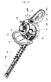
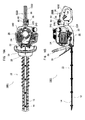
- the hand-held engine-powered tool (hereinafter, engine-powered tool according to this Embodiment is primarily composed of a blade 10, a tool body (body) 20 and a rear handle 30, as shown in FIGS. 1A and 1B .
- the blade 10 is composed of a lower blade 12 and an upper blade 14. Material positioned between the upper blade 14 and the lower blade 12 is trimmed when the later-described engine 24 moves the upper blade 14 and the lower blade 12 back and forth via a centrifugal clutch (not shown) and an eccentric cam (not shown).
- Tool body 20 preferably has a support stand 22 and an engine 24.
- the engine 24 is preferably loaded on the support stand 22.
- a starter handle 242 is preferably formed which may be on the upper right of the engine 24 as shown in FIG. 1A .
- a fuel tank 240 is preferably formed on the right side as shown in FIG. 1A .
- the support stand 22 preferably houses a centrifugal clutch (not shown) inside. The centrifugal clutch transmits driving power to the lower blade 12 when the revolutions of the engine 24 increase, and interrupts power to the lower blade 12 when the revolutions of the engine 24 decrease.
- the lower blade 12 of the blade 10 alternates back and forth, via the centrifugal clutch, due to drive power generated by the engine 24. This back and forth motion trims material that an operator desires to trim.
- a hand guard 26 and a front handle 28 are preferably formed on the left side of the engine 24 on the support stand 22 as shown in FIG. 1A .
- the hand guard 26 is intended to block cut material trimmed by the blade 10 from shooting towards the operator.
- the hand guard 26 is preferably roughly board-shaped and preferably extends from support stand 22 so as to protrude toward the upper left as shown in FIG. 1B .
- the front handle 28 along with the later-described rear handle 30 are preferably provided to allow an operator to grip the engine-powered tool 1.
- the front handle 28 is preferably U-shaped and is preferably positioned above the hand guard 26 (as shown in FIG. 1B ).
- the rear handle 30 preferably has a handle body 32, a throttle lever (operation unit) 34, a safety lever 36, a stop switch 38 and a rotation lock member (limiting member) 40.
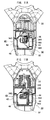
- a detailed disassembled diagram of the rear handle 30 is shown in FIG. 2 .
- the handle body 32 along with the front handle 28 preferably allow gripping of the engine-powered tool 1, as shown in FIG. 2 .
- the handle body 32 is preferably roughly D-shaped.
- the handle body 32 has formed in it a roughly cylindrical body connector 320 that preferably connects to the support stand 22.
- the throttle lever 34 is preferably used to adjust the supply of mixed gas to the engine 24.
- the throttle lever 34 is preferably roughly L-shaped and preferably has a rotational axis 50 formed substantially at its center. As shown in FIG. 2 , pulling on edge 340 of the throttle lever 34, which preferably protrudes within the handle body 32, in the counterclockwise direction forces the throttle lever 34 to rotate about the rotational axis 50 in the counterclockwise direction. The amount of mixed gas supplied to the engine 24 increases as the throttle lever 34 rotates further in the counterclockwise direction. In addition, when the throttle lever 34 is not pulled, the engine 24 is preferably idle with revolutions lower than that necessary for the centrifugal clutch (not shown) to interrupt transmission of drive power to the lower blade 12.
- an electrode terminal 344 (also called a drive control device or second electrode terminal) 344 is attached to the other edge 340 of the throttle lever 34.
- a later-described electrode terminal 482 also called a drive control device of the first electrode terminal
- the supply of electric power to a later-described ignition device 246 is stopped.
- the function of the electrode terminal 344 will be described hereafter with reference to FIG. 9 .
- the safety lever 36 preferably limits inadvertent triggering of the throttle lever 34.
- the safety lever 36 preferably has a rotational axis 52 in its center and preferably has a protrusion 360 extending downward from the rotational axis 52, as shown in Figs 3A and 3B .
- the protrusion 360 of the safety lever 36 abuts the throttle lever 34, restricting counterclockwise movement of the throttle lever 34.
- the state shown in FIG. 3B depicts the safety lever 36 rotated clockwise about the rotational axis 52, which separates the protrusion 360 of the safety lever 36 from the throttle lever 34, allowing counterclockwise movement of the throttle lever 34.
- the stop switch 38 is preferably on top of the handle body 32 as shown in FIG. 3A .
- the stop switch 38 preferably ceases the supply of electric power to the later-described ignition device 246. The detailed functions of the stop switch will be described hereafter with reference to FIG. 9 .
- the rotation lock member 40 is preferably inside the rear handle 30 preferably near support stand 22.
- the rotation lock member 40 preferably includes a slide body 41 preferably in the shape of a rectangular solid, a terminal supporter 48 that perpendicularly intersects slide body 41, and an engagement stop protrusion (rotational position determining unit) 486 that engages with the later-described press insertion indentations (rotational position determining unit) 222 of support stand 22. These features are shown in FIGS. 6A-6B of support stand 22, and are shown enlarged in FIGS. 4A-4B .
- the slide body 41 preferably has rubbing parts 46 capable of rubbing on the handle body 32 preferably on both side surfaces preferably roughly orthogonal to the side surface of the handle body 32, enabling reciprocating movement of the rotation lock member 40 in the rear handle 30.
- Support holes 480 for supporting the electrode terminal 482 shown in FIGS. 2 , 3A and 3B are preferably formed in the terminal supporter 48.
- the electrode terminal 482 stops the supply of electric power to the later-described ignition device 246.
- the functions of the electrode terminal 482 will be described further below with reference to FIG. 9 .
- protrusion 484 (limiting release prevention parts or engagements) is preferably integrated with the top of terminal supporter 48, as shown in FIGS. 4A and 4B . Detailed operation of the protrusions 484 will be explained hereafter.
- the press insertion protrusion 486 extends toward the handle connector 220 provided in the tool body 20 as shown in FIGS. 3A and 3B , roughly on the same plane as the terminal supporter 48.
- press insertion indentations 222 (see FIGS. 6A and 6B ), which preferably engages with the press insertion protrusion 486, are preferably positioned on the handle connector 220, which is preferably operably connected to the rear handle 30.
- the press insertion protrusion 486 preferably engages with the press insertion indentations 222 provided in the handle connector 220 of the support stand 22 and anchor the rear handle 30 to the support stand 22.
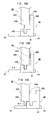
- rotation lock member 40 that preferably locks rotation of the rear handle 30 will be described hereafter with reference to FIGS. 5A, 5B, 5C, 5D , 6A and 6B .
- the press insertion indentations 222 into which the press insertion protrusion 486 preferably engages are preferably positioned in five locations centered about the rotational axis, with a spacing of preferably approximately 35° each.
- the operator rotates the rear handle 30.
- the press insertion protrusion 486 is positioned at an angle facing a given press insertion indentation 222, the operator pushes the side surface 42 (hereafter referred to as the fixed side surface) to the throttle lever 34 side of the slide body 41 shown in Figs 4A and 4B .
- This causes the side surface 44 (hereafter called the anchor release side surface) on the terminal supporter 48 side of the slide body 41 to protrude from the side surface of the handle body 32.
- the press insertion protrusion 486 engages with a press insertion indentation 222 and rotation of the rear handle 30 is locked.
- the anchor side surface 42 preferably protrudes from the side surface of the handle body 32. Accordingly, the press insertion protrusion 486 is disengaged from the press insertion indentation 222, enabling the rear handle 30 to rotate.
- An engagement stop protrusion 224 is preferably formed in one location on the handle connector 220 provided on the support stand 22, as shown in FIGS. 8A and 8B .
- engagement stop holes 324 which are adapted to engage with the engagement stop protrusion 224, are preferably formed in five locations at approximately 35° intervals about the axis of rotation on the body connector 320 of the handle body 32.
- the engagement stop holes 324 are preferably formed with the same angular spacing as the press insertion indentations 222 so that the press insertion protrusion 486 and the press insertion indentation 222 are aligned when the engagement stop protrusion 224 engages with an engagement stop hole 324, as shown in FIGS. 6A and 6B . In this manner, the resistance and the sound made when stop protrusion 224 engages with an engagement stop hole 324, signals the operator that the press insertion protrusion 486 is aligned with a press insertion indentation 222.
- the operator can engage the press insertion protrusion 486 and a press insertion indentation 222 by pushing the fixed side surface of the rotational lock member 40, making anchoring of the rear handle 30 seamless.
- the number and angle of the engagement stop holes 324 and press insertion indentations 22 may be arbitrarily changed in accordance with the specifications targeted.
- Supplying of electric power to the sparkplug 248 in the engine 24 will be described hereafter with reference to FIG. 9 .
- Supplying of electric power to the sparkplug 248 is preferably attained through an engine generator 244 that generates electricity through the power of the engine 24, and an ignition device 246 preferably electrically connected to a terminal of engine generator 244.
- Engine operator 244 impresses an ignition voltage on the sparkplug 248.
- the stop switch 38 is preferably made up of an opening and closing switch and is preferably electrically connected between two output terminals of engine generator 244. When stop switch 38 is closed, the two output terminals of engine generator 244 are short-circuited. Consequently, the supply of electric power for ignition to the ignition device 246 from the engine generation 244 is halted and the supply of electric power to the sparkplug 248 from the ignition device 246 is halted.
- the electrode terminal 344 is preferably formed on the throttle lever 34 and is preferably connected to one of the output terminals of the engine generator 244, and in addition, the electrode terminal 482 provided on the rotation lock member 40 is preferably electrically connected to the other output terminal of the engine generator 244.
- the electrode terminal 344 positioned on the other end 342 of the throttle lever 34 preferably makes contact with the electrode terminal 482, which is triggered by the operation of the throttle lever 34, so that the two output terminals of the engine generator 244 are short-circuited. As a result, the supply of electric power for ignition to the ignition device 246 from the engine generation 244 is halted and the supply of electric power to the sparkplug 248 from the ignition device 246 is halted.
- FIG. 10A shows the state with the rotation lock member 40 positioned in a rotatable position and the throttle lever 34 pulled.
- the press insertion protrusion 486 is preferably released from the press insertion indentation 222 and the rear handle 30 becomes rotatable.
- the terminal support member 48 of rotation lock member 40 preferably moves near the throttle lever 34, as shown in FIGS. 10B , 11A and 11B .
- the throttle lever 34 preferably rotates about the axis of rotation 50.
- the electrode terminal 344 on the other end 342 of the throttle lever 34 makes contact with the electrode terminal 482, which is preferably on terminal support unit 48 of the rotation lock member 40, as shown in FIGS. 10B , 11A and 11B .
- the terminal support unit 48 of the rotation lock member 40 is positioned near the throttle lever 34, the position of the terminal 344 and the electrode terminal 482 is not affected; therefore, pulling of the throttle lever 34 is still necessary in order for the terminal 344 and the electrode terminal 482 to contact each other. Consequently, if the throttle lever 34 is not pulled, the engine 24 enters an idling state in which the drive power of the engine 24 does not flow to the blade 10, so the operator can rotate the rear handle 30 without stopping the engine 24.
- FIG. 12A which show anchor release side surface 44 of the rotation lock member 40 in a pressed state after the rotation lock member 40 is positioned at the rotation lock position and the throttle lever 34 is pulled.
- a variation on the rotation lock member 40 having a function preventing the change from a state in which the rotation lock member 40 limits rotation of the rear handle 30 while the throttle lever 34 is pulled (the operation state of the engine-powered tool 1 ) to a state in which the rotation lock member 40 permits rotation of the rear handle 30 will be described hereafter with reference to FIGS. 14A, 14B and 14C .
- the throttle lever 34 preferably has, on the other end 342, an engagement protrusion 346 (limit release prevention unit, engagement) that protrudes toward the rotation lock member 40. Furthermore, according to this embodiment, in the slide body 41 of the rotation lock member 40, a receiving hole 412 is preferably formed at a position that is aligned with the engagement protrusion 346 in a rotation release state (the state positioned to the left edge as shown in FIGS. 14A and 14B ).
- rotation lock member 40 is preferably positioned in a rotatable position as shown in FIG. 14A , and when the throttle lever 34 is pulled as shown in FIG. 14B , the other end 342 is positioned below.
- the electrode terminal 344 and the electrode terminal 482 preferably make contact, short-circuiting the two output terminals of the engine generator 244.
- the supply of electric power to the ignition device 246 from the engine generator 244 is halted and the supply of electric power to the sparkplug 248 from the ignition device 246 is halted.
- a receiving hole 412 is formed in the slide body 41, there is no interference between the engagement protrusion 346 and the surface of the slide body 41.
- FIG. 14C shows rotation lock member 40 positioned at the rotation lock position (the position on the right side of the position of the rotation lock member 40 in FIG. 14A ).
- throttle lever 34 has been pulled and the other end 342 is positioned at the bottom.
- the engagement protrusion 346 interferes with the side surface of the slide body 41, preventing the rotation lock member 40 from moving to the rotatable position.
- the engagement protrusion 346 acts as a limit release prevention unit.
- rotation of the rear handle 30 is locked and a change to a rotatable state is prevented when the throttle lever 34 is in a pulled state.
- the engine-powered tool 1 preferably stops powering of the engine 24 when the throttle lever 34 is pulled while rotation of the rear handle 30 is permitted, thereby preventing inadvertent trimming of an unintended location while rotating the rear handle 30.
- the electrode terminal 482 preferably formed on the rotation lock member 40 preferably makes contact with the electrode terminal 344 preferably provided on the throttle lever 34. Through this contact, the output terminals of the engine generator 244 are short-circuited, stopping the supply of electric power to the sparkplug 248. Through this, it is possible to prevent the blade 10 from operating during rotation of the rear handle 30.
- an engagement stop protrusion 224 is provided in a set location on the handle connector 220, which is preferably provided on the support stand 22, and a plurality of engagement stop holes 324 are preferably provided in the body connector 320 of the handle body.
- the rear handle 30 can be anchored by pressing on the anchor side surface of the rotation lock member 40, allowing the press insertion protrusion 486 to engage easily with press insertion indentation 222.
- the present application is not limited to the trimmer described in the disclosed embodiments, and can be applied to cutters or saws.
- the present application depicts arrangements short-circuiting the output terminals of the engine generator 24 and interrupting electric power supplied to the sparkplug 248 by having the electrode terminal 482 preferably formed on rotation lock member 40 to preferably come in contact with the electrode terminal 344 provided on the throttle lever 34.
- the electrode terminal 482 preferably formed on rotation lock member 40 to preferably come in contact with the electrode terminal 344 provided on the throttle lever 34.
- other arrangements for interrupting electric power supplied sparkplug 248, such as, for example, using micro-computer controls, or, alternatively, an arrangement for limiting the amount of fuel-air mixture supplied which either stops engine 24 or idles engine 24 may also be used.
- FIGS. 17 through 25 An engine-powered tool 1001 according to embodiment 2 of the present application will be described hereafter with reference to FIGS. 17 through 25 .
- Members that are the same as members described for the engine-powered tool 1 according to Embodiment I above of the present invention are labeled with the same numbers, and explanation of such will be omitted here.
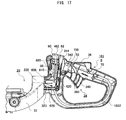
- the rear handle 1030 (hereinafter referred to simply as the handle of the engine-powered tool 1001) is preferably virtually the same as the engine-powered tool 1 according to embodiment 1, and is preferably made up of a handle body 1032, a throttle lever (operation lever) 34, a safety lever 36, a stop switch 38, a lock release button (first operation unit) 60 and a lock button (second operation unit) 62.
- FIG. 17 shows a detailed cross-sectional view of rear handle 1030.
- handle body 1032 is preferably used concurrently with the front handle 28 for gripping the engine-powered tool 1001.
- the handle body 1032 is preferably roughly D-shaped.
- the handle body 1032 is preferably formed so that the preferably roughly cylindrical body connector 320 (see FIG. 18C ) protrudes and operably connects to the support frame 22.
- a slit 322, through which the later-described press insertion protrusion 606 (also called the limiting device or the rotational position determining unit) preferably passes is preferably formed in the body connector 320.
- a slit 323, through which the later-described protrusion 626 preferably passes is preferably formed facing the slit 322.
- the throttle lever 34 is preferably used for regulating the supply of mixed gas to the engine 24.
- the throttle lever 34 is preferably formed in a roughly L-shape and is preferably rotatably supported by a rotation axis 50 substantially in the middle of the handle body 1032.
- one end 340 preferably protrudes from the bottom surface of the handle body 1032.
- a wire 70 is preferably connected to the other end 342.
- the wire 70 preferably passes through the inside of the handle body 1032, with one end preferably anchored to the other end 342 of the throttle lever 34 and the other end preferably anchored to a valve (not shown) that regulates the supply of mixed gas.
- the throttle lever 34 By pressing the one end 340 of the throttle lever 34 upward, the throttle lever preferably rotates in a counterclockwise direction, as shown in FIG. 17 , about the rotation axis 50. Mixed gas supplied to the engine 24 increases as throttle lever 34 rotates further in the counterclockwise direction, which means workload is increasing.
- the engine 24 when the throttle lever 34 is not pulled, the engine 24 preferably falls below a prescribed number of revolutions and the engine 24 idles. In this case, a centrifugal clutch (not shown) cuts the transmission of power to the lower blade 12 from the engine 24.
- an electrode terminal (also called a drive control device or the second electrode terminal) 344 is preferably attached to the other end 342 of the throttle lever 34 and preferably stops the supply of electric power to the later-described ignition device 246 by making contact with the later-described electrode terminal (also called the drive control device or first electrode terminal) 482.
- the safety lever 36 preferably limits inadvertent operation of the throttle lever 34.
- the safety lever 36 preferably has a rotation axis 52 substantially in the middle and a protrusion 360 that protrudes downward from the rotation axis 52, as shown in FIG. 17 .
- the protrusion 360 of the safety lever 36 preferably abuts the throttle lever 34, limiting the effect of pulling the throttle lever 34.
- the safety lever 36 preferably permits the throttle lever 34 to rotate clockwise about the rotation axis 52 so that the protrusion 360 of the safety lever 36 does not abut the throttle lever 34.
- Stop switch 38 is preferably formed on the top of the handle body 1032 as shown in FIGS. 15 , 16A and 16B and is preferably made up of a switch that preferably stops the supply of electric power to the later-described ignition device 246 when closed.
- the electrical composition of the stop switch 38 will be described hereafter.
- the rear handle 1030 is preferably provided with a lock button 62 for locking rotation of the rear handle 1030 with respect to the tool body 20 and lock release button 60 for releasing the lock.
- the lock release button 60 and lock button 62 will be described hereafter with reference to FIGS. 17 , 18A, 18B and 18C .
- the lock release button 60 is preferably provided on the top surface of the handle body 1032 and is preferably supported on the handle body 1032 so as to be capable of moving up and down in a roughly vertical direction on the top surface of the handle body 1032.
- the lock release button 60 is preferably positioned on the top surface of the handle body 1032 in a position where the operator can readily operate lock release button 60 with their thumb while gripping the rear handle 1030.
- the press insertion protrusion 606 that engages with the press insertion indentations (also called indentations or rotational position determining units) 222 described below with reference to FIG. 18C is preferably integrally formed on the lock release button 60.
- the press insertion protrusion 606 is preferably bent in an L-shape in the direction of the handle connector 220 of the tool body 20 and is positioned at the slit 322 of the body connector 320.
- the lock release button 60 is constantly spring-loaded in the direction protruding to the outside of the tool body 20 by a spring (elastic member) 600.
- the lock button 62 is preferably provided on the top surface of the handle body 1032 and is preferably positioned closer to the rear handle 1030 than the lock release button 60.
- the lock button 62 is preferably supported on the handle body 1032 so as to be capable of moving up and down in a preferably roughly vertical direction on the top surface of the handle body 1032.
- the lock button 62 like the lock release button 60, is preferably positioned on the top surface of the handle body 1032 in a position where an operator can readily operate this button with their thumb when gripping the rear handle 1030.
- a protrusion 626 that is adapted to engage with press insertion indentations 222 described below with reference to FIG. 18C is preferably formed integrally on the lock button 62.
- the protrusion 626 is preferably bent in an L-shape in the direction of the handle connector 220 of the tool body 20 and is preferably positioned at the slit 323 of the body connector 320.
- the lock button 62 is preferably constantly spring-loaded by spring 620 in an outward direction from the tool body 20.
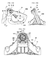
- the press insertion indentations 222 are formed radially in eight locations at preferably approximately 45° intervals centered on the axis of rotation, in the handle connector 220 of the tool body 20 connected to the rear handle 1030.
- the press insertion indentations 222 preferably engage with protrusion 626 when the lock button 62 is operated, and engage with press insertion protrusion 606 when lock release button 60 is pressed.
- the rear handle 1030 is anchored in the rotational direction with respect to the support frame 22 by the press insertion protrusion 606 engaging with press insertion indentations 222.
- the engagement stop unit of the lock release button 60 and the lock button 62 will be described hereafter with reference to FIGS. 19A, 19B , 20A and 20B , in which the tool body 20 and the rear handle 1030 are perpendicular to each other.
- a lock plate 610 is preferably anchored to the lock release button 60 so as to extend in the swinging direction of the lock release button 60.
- the lock plate 610 is preferably on the lock button 62 side of the press insertion protrusion 606 and preferably has an engagement stop protrusion (engagement stop unit) 608 with a triangular cross-section that preferably protrudes to the lock button 62 side.
- an engagement stop release protrusion 609 is preferably formed on the bottom edge of the lock plate 610.
- An engagement stop protrusion (engagement stop unit) 328 that preferably protrudes toward the lock release button 60 side is preferably formed on the surface of a rib 329, which is preferably formed in the handle body 1032 facing the engagement stop protrusion 608.
- the engagement stop protrusion 328 which preferably has a triangular cross-section, and the bottom surface of the engagement stop protrusion 328 preferably engages into the top surface of the engagement stop protrusion 608.
- an engagement stop release protrusion 629 preferably having a trapezoidal cross-section is preferably formed on the side surface of the lock button 62 facing the lock plate 610.
- anchoring of the rear handle 1030 and tool body 20 in the direction of rotation is preferably accomplished by the engagement stop protrusion 606 preferably formed integrally with the lock release button 60 interlocking in one of the press insertion indentations 222.
- the lock release button 60 is preferably pressed to the handle body 1032 side in resistance to the spring-loaded force of the spring 600. Accordingly, the press insertion protrusion 606 is disengaged from the press insertion indentation 222, and the rear handle 1030 can rotate with respect to the main body 20.
- the engagement stop protrusion 608 preferably formed on the lock plate 610 of the lock release button 60 preferably locks into the engagement stop protrusion 328 formed in the rib 329 of the handle body 1032 in order to maintain a rotatable state.
- the lock button 62 When returning to the anchored state, the lock button 62 is pressed toward the handle body 1032 side with resistance to the spring-loaded force of the spring 620. Accordingly, the engagement stop release protrusion 609 is forced upward to the top of the lock release protrusion 629, the lock plate 610 deforms, and the engagement stop protrusion 608 is disengaged from the engagement stop protrusion 328 , as shown in FIG. 20B .
- the engagement stop protrusion 608 When the engagement stop protrusion 608 is disengaged from the engagement stop protrusion 328, the lock release button 60 and the press insertion protrusion 606, anchored to the lock release button 60, move upward under the force of the spring 600. Through this, the press insertion protrusion 606 engages with a press insertion indentation 222 and the tool body 20 and rear handle 1030 become anchored.
- FIGS. 21A, 21B, 21C , 22A, 22B and 22C The anchoring and anchor release action of tool body 20 and the rear handle 1030, when the tool body 20 is inclined on the rear handle 1030, will be described hereafter with reference to FIGS. 21A, 21B, 21C , 22A, 22B and 22C .
- FIGS. 21A, 21B and 21C show the state in which the rear handle 1030 rotated approximately 22.5° in the counterclockwise direction from a position orthogonal to the tool body 20.
- the press insertion protrusion 606 and the protrusion 626 are not aligned with any insertion indentation 222 of the handle connector 220 as shown in FIG. 21C .
- the lock button 62 is pressed in this state, the protrusion 626 contacts the inner surface of the handle connector 220 and does not enter a press insertion indentation 222. Accordingly, movement of the lock button 62 to the inside of the handle body 1032 is inhibited, so engagement of the engagement stop protrusion 328 and the engagement stop protrusion 608 is maintained, as shown in FIGS. 19A and 19B .
- FIGS. 22A, 22B and 22C show a state in which the rear handle 1030 is rotated approximately 45° in the counterclockwise direction from a position orthogonal to the tool body 20.
- the press insertion protrusion 606 and the protrusion 626 are aligned with press insertion indentations 222 of the handle connector 220.
- the lock button 62 is pressed, the protrusion 626 enters and engages with insertion indentation 222, as shown in FIG. 22C .
- the lock button 62 moves toward the inside of the handle body 1032, and the engagement stop protrusion 328 disengages from the engagement stop protrusion 608, as shown in FIGS. 20A and 20B .
- the lock button 62 protrudes toward the outside of the tool body 20 under the force of the spring 600.
- the press insertion protrusion 606 engages with the press insertion indentation 222, and the rear handle 1030 becomes anchored to the tool body 20.
- FIG. 23 is a cross-section taken along line B-B in FIG. 22A , which is to the blade 10 side of the cross-section along line A-A.
- a plate spring 80 is preferably provided on the bottom of the handle connector 220, bent toward the body connector 320.
- An engagement stop protrusion 800 is preferably formed preferably substantially in the center of the plate spring 80 in the latitudinal direction.
- the engagement stop protrusion 800 preferably constantly abuts the outer surface of the body connector 320 under the elastic force of the plate spring 80.
- engagement stop holes 324 are preferably formed at five locations at preferably approximately 45° intervals about the axis of rotation on the outer surface of the body connector 320.
- the engagement stop holes 324 are preferably formed with the same angular spacing as the press insertion indentations 222 so that the press insertion protrusion 606 and the press insertion indentations 222 align with each other when the engagement stop protrusion 800 and the engagement stop holes 324 lock together.
- the operator will be signaled that the engagement stop protrusion 606 is positioned in alignment with the press insertion indentation 222 through the sound and resistance of the engagement stop protrusion 800 engaging with an engagement stop hole 324.
- the operator can, upon being signaled that rear handle 1030 is anchorable, press the lock button 62 to engage the press insertion protrusion 606 and the press insertion indentation 222, so that the rear handle 1030 can be readily anchored.
- the angles and number of engagement stop holes 324 and press insertion indentations 222 may be arbitrarily changed in accordance with the desired specifications.
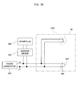
- the supply of electric power to the sparkplug 248 in the engine 24 will be described hereafter with reference to FIG. 24 .
- the supply of electric power to the sparkplug 248 is accomplished by an engine generator 244 that generates electricity through power from the engine 24, and an ignition device 246 that is connected to a terminal of the engine generator 244 and preferably impresses an ignition voltage on the sparkplug 248.
- a stop switch 38 is preferably electrically connected between the two output terminals of the engine generator 244. When the stop switch 38 is closed, the two output terminals of the engine generator 244 are short-circuited. As a result, the supply of electric power for ignition to the ignition device 246 from the engine generator 244 is halted, thereby halting the supply of electric power to the sparkplug 248 from the ignition device 246.
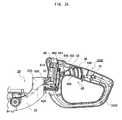
- FIG. 25 omits the lock button 62 in order to show the necessary parts of this structure.
- An electrode terminal 482 that preferably extends toward the lock button 62 side is anchored to the lock release button 60.
- an electrode terminal 344 that preferably extends toward to the lock release button 60 side is anchored on the other end 342 of the throttle lever 34.
- the electrode terminal 344 is preferably positioned so as to contact the electrode terminal 482 when the throttle lever 34 is pulled while the lock release button 60 is in a pressed state (rotatable state).
- the electrode terminal 344 is preferably positioned so as to not contact the electrode terminal 482 when the lock release button 60 is not pressed or when the throttle lever 34 is not being pulled.
- the electrode terminal 344 is preferably electrically connected to one of the output terminals of the engine generator 244.
- the electrode terminal 482, which is preferably provided on the lock release button 60, is preferably electrically connected to the other output terminal of the engine generator 244.
- the electrode terminal 344, which is preferably positioned on the other end 342 of the throttle lever 34, preferably makes contact with the electrode terminal 482 accompanying operation of the throttle lever 34, and the two output terminals of the engine generator 244 are short-circuited. As a result, the supply of electric power for ignition to the ignition device 246 from the engine generator 244 is halted, therefore also halting the supply of electric power to the sparkplug 248 from the ignition device 246.
- the lock release button 60 and the lock button 62 are preferably positioned near each other on opposite sides of the throttle lever 34 in the handle body 1032.
- the operator can accomplish the handle lock release operation and the rotation lock operation separately with the lock release button 60 and lock button 62, and because the positioning is concentrated, can readily adjust the angle of the rear handle 1030 smoothly without significantly disrupting the operator from operating the throttle lever 34.
- the operator can confirm whether the rear handle 1030 is in a rotatable state or a rotation lock state.
- the engagement stop protrusion 608 provided on the lock release button 60 and the engagement stop protrusion 328 provided on the handle body 1032 are engaged. Through this, it is possible to maintain the rotatable state without applying any particular force. Furthermore, by simply pressing the lock button 62, the engagement stop protrusion 328 can be disengaged from the engagement stop protrusion 608 which is provided on the lock release button 60. Furthermore, the press insertion protrusion 606 provided on the lock release button 60 is forced by spring 600 in a direction that achieves a rotation lock state. Accordingly, by disengaging the engagement stop protrusion 608 and the engagement stop protrusion 328, it is possible to switch the rear handle 1030 to an unrotatable state from a rotatable state.
- press insertion indentations 222 are preferably formed in the handle connector 220 in multiple locations, so as to respectively align with each other. Consequently, when the press insertion protrusion 606 is not aligned with a press insertion indentation 222, the protrusion 626 is also not aligned with a press insertion indentation 222; therefore, operation of the lock button anchored to the protrusion 626 is prevented, application of unreasonable force to the lock button 62 and the press insertion protrusion 606 is prevented, and the life of the engine powered tool 1001 can be extended.
- the electrode terminal 482 provided on the lock release button 60 and the electrode terminal 344 provided on the throttle lever 34 contact each other. Through this contact, the output terminals of the engine generator 244 are short-circuited and the supply of electric power to the sparkplug 248 is halted. Through these foregoing actions, it is possible to prevent blade 10 from moving during rotation of the rear handle 1030.
- a plate spring 80 having an engagement stop protrusion 800 is preferably formed in one area of the handle connector 220, which is preferably provided on support stand 22.
- a plurality of engagement stop holes 324 are preferably provided on the body connector 320 of the handle body 1032.
- the press insertion protrusion 606 and the press insertion indentation 222 can be readily engaged by pressing the lock button 62, making it possible to anchor the rear handle 1030.
- the present application is not limited to the trimmer recited, and can also be applied to cutters or chain saws.
- the present application includes an arrangement for short-circuiting the output terminals of the engine generator 244 and interrupting electric power supplied to the sparkplug 248 by having the electrode terminal 482 provided on the lock release button 60 to come into contact with electrode terminal 344 provided on the throttle lever 34.
- other arrangements for interrupting the electric power supplied to the sparkplug 248 may be utilized, such as, for example, micro-computer controls, or an arrangement that limits the amount of fuel-air mixture supplied and, either stops the engine 24 or places it into an idling state, may be utilized.
Landscapes
- Life Sciences & Earth Sciences (AREA)
- Forests & Forestry (AREA)
- Biodiversity & Conservation Biology (AREA)
- Ecology (AREA)
- Environmental Sciences (AREA)
- Engineering & Computer Science (AREA)
- Mechanical Engineering (AREA)
- Wood Science & Technology (AREA)
- Harvester Elements (AREA)
- Portable Power Tools In General (AREA)
- Ignition Installations For Internal Combustion Engines (AREA)
Abstract
Description
- This application claims the benefit of Japanese Patent Application
2008-316200, filed on December 11, 2008 2009-105732, filed on April 23, 2009 - This application relates generally to a hand-held engine-powered tool equipped with a handle that rotates about the main body of the tool.
- In the past, engine-powered tools for trimming the foliage of hedges, etc., were ergonomically structured to allow angle alteration by rotating and setting the handle of the tool relative to the trimming position and the operator's stance. In addition, a structure that prevented the blade from moving was utilized in order to prevent inadvertent trimming of unintended locations when rotating the handle.
- For example,
Patent Literature 1 discloses art for locking the throttle lever immovable while the handle is in rotatable state. This is done by using a lever compound body connected to a protrusion that locks rotation of the handle by fitting into grooves provided in the tool body and a lever member of the throttle lever that abuts the throttle anchor lever. - Patent Literature 1: Unexamined Japanese Patent Application KOKAI Publication No.
2005-160303 - In the art disclosed in
Patent Literature 1, when the tool is in a rotatable state the protrusion that locks rotation of the handle is constantly spring-loaded in the locking direction by a spring. As a result, when there is a plurality of grooves capable of fitting the protrusion, the lock release operation must be executed multiple times or the rotation action must be executed while continually pulling the lock release lever in opposition to the spring's force, making smooth angle changes difficult to accomplish.
The present application addresses the above problem and seeks to attain a hand-held engine-powered tool that prevents operation of the cutting blade while the handle is rotatable and enables shifting between handle rotation and rotation locking through a simple operation. In order solve the above problem, the hand-held engine-powered tool according to a first embodiment of the present application is characterized by an engine having an ignition device. A body supports the engine. A handle is rotatably connected to the body. A limiting member anchors the handle to the body, limiting rotation of the handle. An operation unit provided on the handle regulates mixed gas supplied to the engine in accordance with the operating amount. And, a drive control device permits driving of the engine when the limiting member is limiting rotation of the handle, and stops driving of the engine when the limiting member permits rotation of the handle and the operation unit is in operating state. The drive control device may permit driving of the engine by supplying electric power for ignition to the ignition device of the engine and stop the engine by stopping the supply of electricity to the ignition device. The limiting member limits rotation of the handle when positioned in a first position, permits rotation of the handle when positioned in a second position and is provided with a first electrode terminal. The operation unit has a second electrode terminal that contacts the first electrode terminal when the operation unit is operated with the limiting member positioned at the second position. And, the drive control device stops the supply of electric power to the ignition device of the engine when the first electrode terminal and the second electrode terminal are in contact.
The limiting member may limit rotation of the handle when positioned in the first position and permit rotation of the handle when positioned in the second position. The limiting member has a limit release prevention unit that prevents the limiting member from changing from the first position to the second position when the operation unit is in operating state. The limit release prevention unit may be provided on the limiting member and is an engagement unit that engages with the operation unit by the limiting member moving toward the second position when the operation unit is in operating state. A rotational position determining unit may be further provided for determining the rotational position between the body and the handle.
The limiting member may be provided on the handle. The plurality of indentations may be provided in the body. And, the limiting member engages with each indentation to serve as the rotational position determining unit.
The handle may be further provided with a plurality of engagement stop holes with the same angular spacing as the angular spacing connecting the plurality of indentations provided on the body and the rotational axis of the handle. The body is further provided with engagement stop protrusions that engage with the engagement stop holes. And, the plurality of engagement stop holes and engagement stop protrusions engage when the indentations and limiting member are aligned.
A centrifugal clutch may further be provided between the engine and the blade driven by the engine, which interrupts the drive power to the blade when the engine falls below a predetermined number of revolutions.
According to another embodiment, a hand-held engine-powered tool comprises an engine. A body supports the engine. A handle is rotatably connected to the body. An operation lever is provided on the handle for regulating mixed gas supplied to the engine in accordance with the operating amount. A limiting device limits the rotation of the handle when positioned in a first position and permitting rotation of the handle when positioned in a second position. A first operation unit moves the limiting device from the first position to the second position. A second operation unit moves the limiting device from the second position to the first position wherein the first operation unit and second operation unit are provided adjacent to each other with substantially the same directions of operation. The first operation unit and second operation unit are provided on the side of the handle opposite to the side where the operation lever of the handle is provided. The first operation unit and second operation unit may be provided in an area where such can be operated by the thumb of the operator when the operator is gripping the handle. The first operation unit may be maintained in a state such that the limiting device is caused to move to the second position from the first position. An elastic member may be mounted on the handle and the limiting device receives an energizing force from the elastic member in the direction of the first position, and an engagement stop unit is provided for maintaining the limiting device in the second position, and the second operation unit releases the engagement stop of the engagement stop unit. The body may be provided with indentations that permit the limiting device to be in the first position, and the second operation unit can be operated only when the limiting device is aligned with the indentation.
A drive control device is may be provided which permits driving of the engine when the limiting device limits rotation of the handle and stops driving of the engine when the limiting device permits rotation of the handle and the operation lever is in operating state.
The drive control device may permit driving of the engine by supplying electric power for ignition to the ignition device of the engine, and stop the engine by stopping the supply of electricity to the ignition device. The limiting device may limit rotation of the handle when positioned in a first position, permit rotation of the handle when positioned in a second position and may be provided with a first electrode terminal;
The operation lever has a second electrode terminal that contacts the first electrode terminal when the operation lever is in operating state with the limiting device positioned at the second position. The drive control device stops the supply of electric power to the ignition device of the engine when the first electrode terminal and the second electrode terminal are in contact.
A rotational position determining unit may be further provided for determining the rotational position between the body and the handle. The limiting device may be provided on the handle. The plurality of indentations may be provided in the body. The limiting member may engage with each indentation to serve as the rotational position determining unit. The handle may be further provided with a plurality of engagement stop holes with the same angular spacing as the angular spacing of the indentations in addition to the plurality of indentations provided in the body. The body is further provided with engagement stop protrusions that engage with the engagement stop holes. And, the plurality of engagement stop holes and engagement stop protrusions engage when the plurality of indentations and the limiting device are aligned.
A centrifugal clutch may be further provided between the engine and the blade driven by the engine, which interrupts the drive power to the blade when the engine falls below a predetermined number of revolutions.
According to another embodiment, a hand-held engine-powered tool comprises an engine. A body supports the engine. A handle is rotatably connected to the body. An operation lever is provided on the handle for regulating mixed gas supplied to the engine in accordance with the operating amount. A limiting device limits rotation of the handle when positioned in a first position and permitting rotation of the handle when positioned in a second position. A first operation unit enables the limiting device to move from the first position to the second position. And, a second operation unit for enabling the limiting device to move from the second position to the first position wherein the first operation unit and second operation unit are provided in an area where such can be operated by the thumb when the operator is gripping the handle. - As noted above, the hand-held engine-powered tool according to the embodiments disclosed in the present application can prevent operation of the blade when rotation of the handle is allowed. In addition, it is possible to readily switch between rotation of the handle and locking of the handle through a simple operation.
- A more complete understanding of this application can be obtained when the following detailed description is considered in conjunction with the following drawings, in which:
-
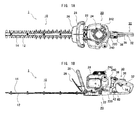
FIG. 1A is a top view of the hand-held engine-powered tool according toEmbodiment 1; -
FIG. 1B is a side view of the engine-powered tool shown inFIG. 1A ; -
FIG. 2 is a disassembled view showing the inside of the operation unit of the engine-powered tool shown inFIG. 1A ; -
FIG. 3A is a partial cross-sectional side view of the throttle lever lock state of the engine-powered tool shown inFIG. 1 A; -
FIG. 3B is a partial cross-sectional side view of the throttle lever unlock state of the engine-powered tool shown inFIG. 1A ; -
FIG. 4A is an oblique view of one side of the rotation lock member of the engine-powered tool shown inFIG. 1A ; -
FIG. 4B is an oblique view of the opposite side of the rotation lock member shown inFIG. 4A ; -
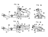
FIG. 5A is a side view showing the handle rotation state of the engine-powered tool shown inFIG. 1A ; -
FIG. 5B is a front view corresponding toFIG. 5A ; -
FIG. 5C is a side view showing a handle rotation state differing from that ofFIG. 5A of the engine-powered tool shown inFIG. 1A ; -
FIG. 5D is a front view corresponding toFIG. 5C ; -
FIG. 6A is a cross-sectional view taken along line A-A inFIG. 5A ; -
FIG. 6B is a cross-sectional view taken along line A-A inFIG. 5C ; -
FIG. 7A is a side view showing a handle rotation state of the engine-powered tool shown inFIG. 1A . -
FIG. 7B is a front view corresponding toFIG. 7A ; -
FIG. 7C is a side view showing a handle rotation state differing from that ofFIG. 7A of the engine-powered tool shown inFIG. 1A ; -
FIG. 7D is a front view corresponding toFIG. 7C ; -
FIG. 8A is a cross-sectional view taken along line B-B inFIG. 7A ; -
FIG. 8B is a cross-sectional view taken along line B-B inFIG. 7C ; -
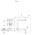
FIG. 9 is a circuit diagram relating to the electrode terminals provided in the throttle lever and rotation lock member of the engine-powered tool shown inFIG. 1A ; -
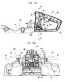
FIG. 10A is a partial cross-sectional view of the engine-powered tool shown inFIG. 1A ; -
FIG. 10B is a cross-sectional view taken along line C-C inFIG. 10A ; -
FIG. 11A is a cross-sectional view taken along line D-D inFIG. 10B ; -
FIG. 11B is a cross-sectional view taken along line E-E inFIG. 10B ; -
FIG. 12A is a partial cross-sectional view of the engine-powered tool shown inFIG. 1A ; -
FIG. 12B is a cross-sectional view taken along line C-C inFIG. 12A ; -
FIG. 13A is a cross-sectional view taken along line D-D inFIG. 12B ; -
FIG. 13B is a cross-sectional view taken along line E-E inFIG. 12B ; -
FIG. 14A shows the handle rotatable state of a variation of the throttle lever and rotation lock member of the engine-powered tool shown inFIG. 1A ; -
FIG. 14B shows the state with the throttle lever pulled inFIG. 14A ; -
FIG. 14C shows the state with the throttle lever pulled in a rotation lock state inFIG. 14A ; -
FIG. 15 is an oblique view showing the engine-powered tool according toEmbodiment 2; -
FIG. 16A is a top view of the engine-powered tool shown inFIG. 15 ; -
FIG. 16B is a side view of the engine-powered tool shown inFIG. 15 ; -
FIG. 17 is a cross-sectional view showing the inside of the handle of the engine-powered tool shown inFIG. 15 ; -
FIG. 18A is a side view of the engine-powered tool shown inFIG. 15 when the handle of the engine-powered tool is vertical; -
FIG. 18B is a front view corresponding toFIG. 18A ; -
FIG. 18C is a cross-sectional view taken along line A-A inFIG. 18A ; -
FIG. 19A is a cross-sectional view showing the handle in a state in which the lock release button has been pressed in the engine-powered tool shown inFIG. 15 ; -
FIG. 19B is an enlarged cross-sectional view showing the engagement stop unit of the lock release button and the lock button of the engine-powered tool in part X shown inFIG. 19A ; -
FIG. 20A is a cross-sectional view of the handle when the lock button has been pressed with the lock release button in a pressed state in the engine-powered tool shown inFIG. 15 ; -
FIG. 20B is an enlarged cross-sectional view showing the engagement stop units of the lock release button and the lock button of the engine-powered tool in part X shown inFIG. 20A ; -
FIG. 21A is a side view of the engine-powered tool shown inFIG. 15 when the handle of the engine-powered tool is in an inclined state; -
FIG. 21B is a front view corresponding toFIG. 21A ; -
FIG. 21C is a cross-sectional view taken along line A-A inFIG. 21A ; -
FIG. 22A is a side view of the engine-powered tool shown inFIG. 15 when the handle of the engine-powered tool is in an inclined state; -
FIG. 22B is a front view corresponding toFIG. 22A ; -
FIG. 22C is a cross-sectional view taken along line A-A inFIG. 22A ; -
FIG. 23 is a cross-sectional view taken along line B-B inFIG. 22A ; -
FIG. 24 is a circuit diagram relating to the electrode terminals provided in the throttle lever and the rotation lock member of the engine-powered tool shown inFIG. 15 ; and -
FIG. 25 is a side cross-sectional view of the handle showing the state when the throttle lever is pulled with the lock release button in a pressed state in the engine-powered tool shown inFIG. 15 . - Embodiment I of the present invention will be described hereafter with reference to the drawings. The hand-held engine-powered tool (hereinafter, engine-powered tool according to this Embodiment is primarily composed of a
blade 10, a tool body (body) 20 and arear handle 30, as shown inFIGS. 1A and 1B . - The
blade 10 is composed of alower blade 12 and anupper blade 14. Material positioned between theupper blade 14 and thelower blade 12 is trimmed when the later-describedengine 24 moves theupper blade 14 and thelower blade 12 back and forth via a centrifugal clutch (not shown) and an eccentric cam (not shown). -
Tool body 20 preferably has asupport stand 22 and anengine 24. Theengine 24 is preferably loaded on thesupport stand 22. Astarter handle 242 is preferably formed which may be on the upper right of theengine 24 as shown inFIG. 1A . In addition, afuel tank 240 is preferably formed on the right side as shown inFIG. 1A . Moreover, the support stand 22 preferably houses a centrifugal clutch (not shown) inside. The centrifugal clutch transmits driving power to thelower blade 12 when the revolutions of theengine 24 increase, and interrupts power to thelower blade 12 when the revolutions of theengine 24 decrease. In addition, thelower blade 12 of theblade 10 alternates back and forth, via the centrifugal clutch, due to drive power generated by theengine 24. This back and forth motion trims material that an operator desires to trim. In addition, ahand guard 26 and afront handle 28 are preferably formed on the left side of theengine 24 on the support stand 22 as shown inFIG. 1A . - The
hand guard 26 is intended to block cut material trimmed by theblade 10 from shooting towards the operator. Thehand guard 26 is preferably roughly board-shaped and preferably extends from support stand 22 so as to protrude toward the upper left as shown inFIG. 1B . - The
front handle 28 along with the later-describedrear handle 30 are preferably provided to allow an operator to grip the engine-poweredtool 1. Thefront handle 28 is preferably U-shaped and is preferably positioned above the hand guard 26 (as shown inFIG. 1B ). - The
rear handle 30 preferably has ahandle body 32, a throttle lever (operation unit) 34, asafety lever 36, astop switch 38 and a rotation lock member (limiting member) 40. A detailed disassembled diagram of therear handle 30 is shown inFIG. 2 . - The
handle body 32 along with thefront handle 28 preferably allow gripping of the engine-poweredtool 1, as shown inFIG. 2 . Thehandle body 32 is preferably roughly D-shaped. In addition, thehandle body 32 has formed in it a roughlycylindrical body connector 320 that preferably connects to thesupport stand 22. - The
throttle lever 34 is preferably used to adjust the supply of mixed gas to theengine 24. Thethrottle lever 34 is preferably roughly L-shaped and preferably has arotational axis 50 formed substantially at its center. As shown inFIG. 2 , pulling onedge 340 of thethrottle lever 34, which preferably protrudes within thehandle body 32, in the counterclockwise direction forces thethrottle lever 34 to rotate about therotational axis 50 in the counterclockwise direction. The amount of mixed gas supplied to theengine 24 increases as thethrottle lever 34 rotates further in the counterclockwise direction. In addition, when thethrottle lever 34 is not pulled, theengine 24 is preferably idle with revolutions lower than that necessary for the centrifugal clutch (not shown) to interrupt transmission of drive power to thelower blade 12. - In addition, an electrode terminal (also called a drive control device or second electrode terminal) 344 is attached to the
other edge 340 of thethrottle lever 34. By making contact with theelectrode terminal 344 to a later-described electrode terminal 482 (also called a drive control device of the first electrode terminal), the supply of electric power to a later-describedignition device 246 is stopped. The function of theelectrode terminal 344 will be described hereafter with reference toFIG. 9 . - The
safety lever 36 preferably limits inadvertent triggering of thethrottle lever 34. Thesafety lever 36 preferably has arotational axis 52 in its center and preferably has aprotrusion 360 extending downward from therotational axis 52, as shown inFigs 3A and 3B . In the state shown inFIG. 3A in which thesafety lever 36 is mostly outside thehandle body 32, theprotrusion 360 of thesafety lever 36 abuts thethrottle lever 34, restricting counterclockwise movement of thethrottle lever 34. In contrast, the state shown inFIG. 3B depicts thesafety lever 36 rotated clockwise about therotational axis 52, which separates theprotrusion 360 of thesafety lever 36 from thethrottle lever 34, allowing counterclockwise movement of thethrottle lever 34. - The
stop switch 38 is preferably on top of thehandle body 32 as shown inFIG. 3A . Thestop switch 38 preferably ceases the supply of electric power to the later-describedignition device 246. The detailed functions of the stop switch will be described hereafter with reference toFIG. 9 . - The
rotation lock member 40 is preferably inside therear handle 30 preferably nearsupport stand 22. Therotation lock member 40 preferably includes aslide body 41 preferably in the shape of a rectangular solid, aterminal supporter 48 that perpendicularly intersectsslide body 41, and an engagement stop protrusion (rotational position determining unit) 486 that engages with the later-described press insertion indentations (rotational position determining unit) 222 ofsupport stand 22. These features are shown inFIGS. 6A-6B ofsupport stand 22, and are shown enlarged inFIGS. 4A-4B . - The
slide body 41 preferably has rubbingparts 46 capable of rubbing on thehandle body 32 preferably on both side surfaces preferably roughly orthogonal to the side surface of thehandle body 32, enabling reciprocating movement of therotation lock member 40 in therear handle 30. - Support holes 480 for supporting the
electrode terminal 482 shown inFIGS. 2 ,3A and 3B are preferably formed in theterminal supporter 48. By making contact with theelectrode terminal 482 to theelectrode terminal 344 formed in thethrottle lever 34, theelectrode terminal 482 stops the supply of electric power to the later-describedignition device 246. The functions of theelectrode terminal 482 will be described further below with reference toFIG. 9 . In addition, protrusion 484 (limiting release prevention parts or engagements) is preferably integrated with the top ofterminal supporter 48, as shown inFIGS. 4A and 4B . Detailed operation of theprotrusions 484 will be explained hereafter. - The
press insertion protrusion 486 extends toward thehandle connector 220 provided in thetool body 20 as shown inFIGS. 3A and 3B , roughly on the same plane as theterminal supporter 48. In addition, in thetool body 20, press insertion indentations 222 (seeFIGS. 6A and 6B ), which preferably engages with thepress insertion protrusion 486, are preferably positioned on thehandle connector 220, which is preferably operably connected to therear handle 30. Thepress insertion protrusion 486 preferably engages with thepress insertion indentations 222 provided in thehandle connector 220 of thesupport stand 22 and anchor therear handle 30 to thesupport stand 22. - The preferred operation of the
rotation lock member 40 that preferably locks rotation of therear handle 30 will be described hereafter with reference toFIGS. 5A, 5B, 5C, 5D ,6A and 6B . - In the
handle connector 220 according to this embodiment, thepress insertion indentations 222 into which thepress insertion protrusion 486 preferably engages are preferably positioned in five locations centered about the rotational axis, with a spacing of preferably approximately 35° each. The operator rotates therear handle 30. When thepress insertion protrusion 486 is positioned at an angle facing a givenpress insertion indentation 222, the operator pushes the side surface 42 (hereafter referred to as the fixed side surface) to thethrottle lever 34 side of theslide body 41 shown inFigs 4A and 4B . This causes the side surface 44 (hereafter called the anchor release side surface) on theterminal supporter 48 side of theslide body 41 to protrude from the side surface of thehandle body 32. Accordingly, thepress insertion protrusion 486 engages with apress insertion indentation 222 and rotation of therear handle 30 is locked. - Conversely, when the anchor
release side surface 44 is pushed, theanchor side surface 42 preferably protrudes from the side surface of thehandle body 32. Accordingly, thepress insertion protrusion 486 is disengaged from thepress insertion indentation 222, enabling therear handle 30 to rotate. - The structure that signals the operator that the
press insertion protrusion 486 is positioned at an angle facing apress insertion indentation 222 when rotating therear handle 30 will be described hereafter with reference toFIGS. 7A, 7B, 7C, 7D ,8A and 8B . Anengagement stop protrusion 224 is preferably formed in one location on thehandle connector 220 provided on thesupport stand 22, as shown inFIGS. 8A and 8B . Furthermore, engagement stop holes 324, which are adapted to engage with theengagement stop protrusion 224, are preferably formed in five locations at approximately 35° intervals about the axis of rotation on thebody connector 320 of thehandle body 32. - The engagement stop holes 324 are preferably formed with the same angular spacing as the
press insertion indentations 222 so that thepress insertion protrusion 486 and thepress insertion indentation 222 are aligned when theengagement stop protrusion 224 engages with anengagement stop hole 324, as shown inFIGS. 6A and 6B . In this manner, the resistance and the sound made whenstop protrusion 224 engages with anengagement stop hole 324, signals the operator that thepress insertion protrusion 486 is aligned with apress insertion indentation 222. Accordingly, upon being signaled that an angle at which therear handle 30 can be anchored was located, the operator can engage thepress insertion protrusion 486 and apress insertion indentation 222 by pushing the fixed side surface of therotational lock member 40, making anchoring of therear handle 30 seamless. As would be understood by one of ordinary skill in the art, the number and angle of the engagement stop holes 324 and pressinsertion indentations 22 may be arbitrarily changed in accordance with the specifications targeted. - Supplying of electric power to the
sparkplug 248 in theengine 24 will be described hereafter with reference toFIG. 9 . Supplying of electric power to thesparkplug 248 is preferably attained through anengine generator 244 that generates electricity through the power of theengine 24, and anignition device 246 preferably electrically connected to a terminal ofengine generator 244.Engine operator 244 impresses an ignition voltage on thesparkplug 248. Next, thestop switch 38 is preferably made up of an opening and closing switch and is preferably electrically connected between two output terminals ofengine generator 244. When stop switch 38 is closed, the two output terminals ofengine generator 244 are short-circuited. Consequently, the supply of electric power for ignition to theignition device 246 from theengine generation 244 is halted and the supply of electric power to thesparkplug 248 from theignition device 246 is halted. - The
electrode terminal 344 is preferably formed on thethrottle lever 34 and is preferably connected to one of the output terminals of theengine generator 244, and in addition, theelectrode terminal 482 provided on therotation lock member 40 is preferably electrically connected to the other output terminal of theengine generator 244. Theelectrode terminal 344 positioned on theother end 342 of thethrottle lever 34 preferably makes contact with theelectrode terminal 482, which is triggered by the operation of thethrottle lever 34, so that the two output terminals of theengine generator 244 are short-circuited. As a result, the supply of electric power for ignition to theignition device 246 from theengine generation 244 is halted and the supply of electric power to thesparkplug 248 from theignition device 246 is halted. - The engine halt operation triggered when the
throttle lever 34 is pulled with therear handle 30 in a rotatable state will be described hereafter with reference toFIGS. 10A, 10B ,11 A and 11B.FIG. 10A shows the state with therotation lock member 40 positioned in a rotatable position and thethrottle lever 34 pulled. - When the anchor
release side surface 44 of therotation lock member 40 is pushed, thepress insertion protrusion 486 is preferably released from thepress insertion indentation 222 and therear handle 30 becomes rotatable. At the same time, theterminal support member 48 ofrotation lock member 40 preferably moves near thethrottle lever 34, as shown inFIGS. 10B ,11A and 11B . When the operator pulls oneedge 340 of thethrottle lever 34 shown inFIG. 10A into thehandle body 32, thethrottle lever 34 preferably rotates about the axis ofrotation 50. At this time, theelectrode terminal 344 on theother end 342 of thethrottle lever 34 makes contact with theelectrode terminal 482, which is preferably onterminal support unit 48 of therotation lock member 40, as shown inFIGS. 10B ,11A and 11B . - In this manner, when the
electrode terminal 344 contacts theelectrode terminal 482, the two output terminals of theengine generator 244 are short-circuited, as shown inFIG. 9 . Consequently, the supply of electric power to theignition device 246 from theengine generator 244 is halted and the supply of electric power to thesparkplug 248 from theignition device 246 is halted. As a result, the action of the piston inside theengine 24 stops. - In addition, although the
terminal support unit 48 of therotation lock member 40 is positioned near thethrottle lever 34, the position of the terminal 344 and theelectrode terminal 482 is not affected; therefore, pulling of thethrottle lever 34 is still necessary in order for the terminal 344 and theelectrode terminal 482 to contact each other. Consequently, if thethrottle lever 34 is not pulled, theengine 24 enters an idling state in which the drive power of theengine 24 does not flow to theblade 10, so the operator can rotate therear handle 30 without stopping theengine 24. - The structure for preventing the switch from entering a state in which the
rotation lock member 40 limits the rotation of therear handle 30, while thethrottle lever 34 is pulled (the operating state of the engine-powered tool 1) to a position in which therotation lock member 40 permits rotation of therear handle 30 is described hereafter with reference toFIGS. 12A, 12B ,13A and 13B .FIG. 12A , which show anchor releaseside surface 44 of therotation lock member 40 in a pressed state after therotation lock member 40 is positioned at the rotation lock position and thethrottle lever 34 is pulled. - In this state, when the operator presses the anchor
release side surface 44 of therotation lock member 40, theprotrusion 484 provided on theterminal support unit 48 as shown inFIG. 13A makes contact with theother end 342 of thethrottle lever 34. As a result, thepress insertion protrusion 486 shown inFIGS. 6A and 6B provided on therotation lock member 40 cannot be disengaged from thepress insertion indentation 222, so the rotation lock of therear handle 30 is not released. In this manner, theprotrusion 484 acts as a limit release prevention unit, so the change to a rotatable state from the state in which rotation of therear handle 30 is locked and thethrottle lever 34 has been pulled can be prevented. - A variation on the
rotation lock member 40 having a function preventing the change from a state in which therotation lock member 40 limits rotation of therear handle 30 while thethrottle lever 34 is pulled (the operation state of the engine-powered tool 1) to a state in which therotation lock member 40 permits rotation of therear handle 30 will be described hereafter with reference toFIGS. 14A, 14B and 14C . - The
throttle lever 34 according to this embodiment preferably has, on theother end 342, an engagement protrusion 346 (limit release prevention unit, engagement) that protrudes toward therotation lock member 40. Furthermore, according to this embodiment, in theslide body 41 of therotation lock member 40, a receivinghole 412 is preferably formed at a position that is aligned with theengagement protrusion 346 in a rotation release state (the state positioned to the left edge as shown inFIGS. 14A and 14B ). - The action of the
throttle lever 34 and therotation lock member 40 according to this embodiment will be described hereafter. First,rotation lock member 40 is preferably positioned in a rotatable position as shown inFIG. 14A , and when thethrottle lever 34 is pulled as shown inFIG. 14B , theother end 342 is positioned below. When this occurs, theelectrode terminal 344 and theelectrode terminal 482 preferably make contact, short-circuiting the two output terminals of theengine generator 244. As a result, the supply of electric power to theignition device 246 from theengine generator 244 is halted and the supply of electric power to thesparkplug 248 from theignition device 246 is halted. At this time, because a receivinghole 412 is formed in theslide body 41, there is no interference between theengagement protrusion 346 and the surface of theslide body 41. -
FIG. 14C showsrotation lock member 40 positioned at the rotation lock position (the position on the right side of the position of therotation lock member 40 inFIG. 14A ). InFIG. 14C throttle lever 34 has been pulled and theother end 342 is positioned at the bottom. In this state, even if the anchorrelease side surface 44 is pressed so that therotation lock member 40 moves to a rotatable position (the left side of the position of therotation lock member 40 inFIG. 14C ), theengagement protrusion 346 interferes with the side surface of theslide body 41, preventing therotation lock member 40 from moving to the rotatable position. In this manner, theengagement protrusion 346 acts as a limit release prevention unit. Thus, rotation of therear handle 30 is locked and a change to a rotatable state is prevented when thethrottle lever 34 is in a pulled state. - The engine-powered
tool 1 according to the above embodiments preferably stops powering of theengine 24 when thethrottle lever 34 is pulled while rotation of therear handle 30 is permitted, thereby preventing inadvertent trimming of an unintended location while rotating therear handle 30. - Specifically, it is possible to stop the
engine 24 by stopping the supply of electric power to theignition device 246 of theengine 24. - More specifically, if the
throttle lever 34 is pulled while therotation lock member 40 permits rotation of therear handle 30, theelectrode terminal 482 preferably formed on therotation lock member 40 preferably makes contact with theelectrode terminal 344 preferably provided on thethrottle lever 34. Through this contact, the output terminals of theengine generator 244 are short-circuited, stopping the supply of electric power to thesparkplug 248. Through this, it is possible to prevent theblade 10 from operating during rotation of therear handle 30. - In addition, by endowing the
rotation lock member 40 with aprotrusion 484 and anengagement protrusion 346, when therotation lock member 40 limits the rotation of therear handle 30 and thethrottle lever 34 is pulled, therotation lock member 40 is prevented from moving to a position that permits rotation of therear handle 30. - Furthermore, by providing a plurality of
press insertion indentations 222 in thehandle connector 220 of thetool body 20 so as to align withpress insertion protrusion 486 of therotation lock member 40, it is possible to anchor therear handle 30 to thetool body 20 at an angle corresponding to a location where anengageable indentation 222 is provided. - Furthermore, an
engagement stop protrusion 224 is provided in a set location on thehandle connector 220, which is preferably provided on thesupport stand 22, and a plurality of engagement stop holes 324 are preferably provided in thebody connector 320 of the handle body. When therear handle 30 is rotated, the operator is signaled when the angle suitable for anchoring therear handle 30 is found, when the engagement stop position, between theengagement stop protrusion 224 and anengagement stop hole 324, matches the position where thepress insertion protrusion 486 and apress insertion indentation 222 are aligned. After the operator is signaled of a possible angle suitable for anchoring therear handle 30, therear handle 30 can be anchored by pressing on the anchor side surface of therotation lock member 40, allowing thepress insertion protrusion 486 to engage easily withpress insertion indentation 222. - Furthermore, by providing a centrifugal clutch (not shown), it is possible to rotate
rear handle 30 while theengine 24 is idle without the operation ofblade 10. By so doing, it is possible to swiftly restart operation after therear handle 30 has been rotated to a desired angle. - The present application is not limited to the trimmer described in the disclosed embodiments, and can be applied to cutters or saws.
- In addition, the present application depicts arrangements short-circuiting the output terminals of the
engine generator 24 and interrupting electric power supplied to thesparkplug 248 by having theelectrode terminal 482 preferably formed onrotation lock member 40 to preferably come in contact with theelectrode terminal 344 provided on thethrottle lever 34. As would be understood by someone of ordinary skill in the art, other arrangements for interrupting electric power suppliedsparkplug 248, such as, for example, using micro-computer controls, or, alternatively, an arrangement for limiting the amount of fuel-air mixture supplied which either stopsengine 24 or idlesengine 24 may also be used. - An engine-powered
tool 1001 according toembodiment 2 of the present application will be described hereafter with reference toFIGS. 17 through 25 . Members that are the same as members described for the engine-poweredtool 1 according to Embodiment I above of the present invention are labeled with the same numbers, and explanation of such will be omitted here. - The rear handle 1030 (hereinafter referred to simply as the handle of the engine-powered tool 1001) is preferably virtually the same as the engine-powered
tool 1 according toembodiment 1, and is preferably made up of ahandle body 1032, a throttle lever (operation lever) 34, asafety lever 36, astop switch 38, a lock release button (first operation unit) 60 and a lock button (second operation unit) 62.FIG. 17 shows a detailed cross-sectional view ofrear handle 1030. - As shown in
FIG. 17 ,handle body 1032 is preferably used concurrently with thefront handle 28 for gripping the engine-poweredtool 1001. Thehandle body 1032 is preferably roughly D-shaped. In addition, thehandle body 1032 is preferably formed so that the preferably roughly cylindrical body connector 320 (seeFIG. 18C ) protrudes and operably connects to thesupport frame 22. In addition, aslit 322, through which the later-described press insertion protrusion 606 (also called the limiting device or the rotational position determining unit) preferably passes is preferably formed in thebody connector 320. Furthermore, aslit 323, through which the later-describedprotrusion 626 preferably passes is preferably formed facing theslit 322. - The
throttle lever 34 is preferably used for regulating the supply of mixed gas to theengine 24. Thethrottle lever 34 is preferably formed in a roughly L-shape and is preferably rotatably supported by arotation axis 50 substantially in the middle of thehandle body 1032. When thethrottle lever 34 is not operated, oneend 340 preferably protrudes from the bottom surface of thehandle body 1032. In addition, awire 70 is preferably connected to theother end 342. Thewire 70 preferably passes through the inside of thehandle body 1032, with one end preferably anchored to theother end 342 of thethrottle lever 34 and the other end preferably anchored to a valve (not shown) that regulates the supply of mixed gas. - By pressing the one
end 340 of thethrottle lever 34 upward, the throttle lever preferably rotates in a counterclockwise direction, as shown inFIG. 17 , about therotation axis 50. Mixed gas supplied to theengine 24 increases asthrottle lever 34 rotates further in the counterclockwise direction, which means workload is increasing. In addition, when thethrottle lever 34 is not pulled, theengine 24 preferably falls below a prescribed number of revolutions and theengine 24 idles. In this case, a centrifugal clutch (not shown) cuts the transmission of power to thelower blade 12 from theengine 24. - In addition, an electrode terminal (also called a drive control device or the second electrode terminal) 344 is preferably attached to the
other end 342 of thethrottle lever 34 and preferably stops the supply of electric power to the later-describedignition device 246 by making contact with the later-described electrode terminal (also called the drive control device or first electrode terminal) 482. These actions will be described in detail hereafter. - The
safety lever 36 preferably limits inadvertent operation of thethrottle lever 34. Thesafety lever 36 preferably has arotation axis 52 substantially in the middle and aprotrusion 360 that protrudes downward from therotation axis 52, as shown inFIG. 17 . Whensafety lever 36 protrudes from thehandle body 1032, theprotrusion 360 of thesafety lever 36 preferably abuts thethrottle lever 34, limiting the effect of pulling thethrottle lever 34. In addition, thesafety lever 36 preferably permits thethrottle lever 34 to rotate clockwise about therotation axis 52 so that theprotrusion 360 of thesafety lever 36 does not abut thethrottle lever 34. - Stop
switch 38 is preferably formed on the top of thehandle body 1032 as shown inFIGS. 15 ,16A and 16B and is preferably made up of a switch that preferably stops the supply of electric power to the later-describedignition device 246 when closed. The electrical composition of thestop switch 38 will be described hereafter. - In addition, the
rear handle 1030 is preferably provided with alock button 62 for locking rotation of therear handle 1030 with respect to thetool body 20 andlock release button 60 for releasing the lock. Thelock release button 60 andlock button 62 will be described hereafter with reference toFIGS. 17 ,18A, 18B and 18C . - The
lock release button 60 is preferably provided on the top surface of thehandle body 1032 and is preferably supported on thehandle body 1032 so as to be capable of moving up and down in a roughly vertical direction on the top surface of thehandle body 1032. Specifically, thelock release button 60 is preferably positioned on the top surface of thehandle body 1032 in a position where the operator can readily operatelock release button 60 with their thumb while gripping therear handle 1030. Furthermore, thepress insertion protrusion 606 that engages with the press insertion indentations (also called indentations or rotational position determining units) 222 described below with reference toFIG. 18C is preferably integrally formed on thelock release button 60. Thepress insertion protrusion 606 is preferably bent in an L-shape in the direction of thehandle connector 220 of thetool body 20 and is positioned at theslit 322 of thebody connector 320. In addition, thelock release button 60 is constantly spring-loaded in the direction protruding to the outside of thetool body 20 by a spring (elastic member) 600. - The
lock button 62 is preferably provided on the top surface of thehandle body 1032 and is preferably positioned closer to therear handle 1030 than thelock release button 60. Thelock button 62 is preferably supported on thehandle body 1032 so as to be capable of moving up and down in a preferably roughly vertical direction on the top surface of thehandle body 1032. Specifically, thelock button 62, like thelock release button 60, is preferably positioned on the top surface of thehandle body 1032 in a position where an operator can readily operate this button with their thumb when gripping therear handle 1030. Furthermore, aprotrusion 626 that is adapted to engage withpress insertion indentations 222 described below with reference toFIG. 18C is preferably formed integrally on thelock button 62. Theprotrusion 626 is preferably bent in an L-shape in the direction of thehandle connector 220 of thetool body 20 and is preferably positioned at theslit 323 of thebody connector 320. In addition, thelock button 62 is preferably constantly spring-loaded byspring 620 in an outward direction from thetool body 20. - In addition, the
press insertion indentations 222 are formed radially in eight locations at preferably approximately 45° intervals centered on the axis of rotation, in thehandle connector 220 of thetool body 20 connected to therear handle 1030. Thepress insertion indentations 222 preferably engage withprotrusion 626 when thelock button 62 is operated, and engage withpress insertion protrusion 606 whenlock release button 60 is pressed. Therear handle 1030 is anchored in the rotational direction with respect to thesupport frame 22 by thepress insertion protrusion 606 engaging withpress insertion indentations 222. - The engagement stop unit of the
lock release button 60 and thelock button 62 will be described hereafter with reference toFIGS. 19A, 19B ,20A and 20B , in which thetool body 20 and therear handle 1030 are perpendicular to each other. - A
lock plate 610 is preferably anchored to thelock release button 60 so as to extend in the swinging direction of thelock release button 60. Thelock plate 610 is preferably on thelock button 62 side of thepress insertion protrusion 606 and preferably has an engagement stop protrusion (engagement stop unit) 608 with a triangular cross-section that preferably protrudes to thelock button 62 side. In addition, an engagementstop release protrusion 609 is preferably formed on the bottom edge of thelock plate 610. - An engagement stop protrusion (engagement stop unit) 328 that preferably protrudes toward the
lock release button 60 side is preferably formed on the surface of arib 329, which is preferably formed in thehandle body 1032 facing theengagement stop protrusion 608. Theengagement stop protrusion 328, which preferably has a triangular cross-section, and the bottom surface of theengagement stop protrusion 328 preferably engages into the top surface of theengagement stop protrusion 608. In addition, an engagementstop release protrusion 629 preferably having a trapezoidal cross-section is preferably formed on the side surface of thelock button 62 facing thelock plate 610. - In addition, anchoring of the
rear handle 1030 andtool body 20 in the direction of rotation is preferably accomplished by theengagement stop protrusion 606 preferably formed integrally with thelock release button 60 interlocking in one of thepress insertion indentations 222. When this anchored state is released, thelock release button 60 is preferably pressed to thehandle body 1032 side in resistance to the spring-loaded force of thespring 600. Accordingly, thepress insertion protrusion 606 is disengaged from thepress insertion indentation 222, and therear handle 1030 can rotate with respect to themain body 20. Theengagement stop protrusion 608 preferably formed on thelock plate 610 of thelock release button 60 preferably locks into theengagement stop protrusion 328 formed in therib 329 of thehandle body 1032 in order to maintain a rotatable state. - When returning to the anchored state, the
lock button 62 is pressed toward thehandle body 1032 side with resistance to the spring-loaded force of thespring 620. Accordingly, the engagementstop release protrusion 609 is forced upward to the top of thelock release protrusion 629, thelock plate 610 deforms, and theengagement stop protrusion 608 is disengaged from theengagement stop protrusion 328 , as shown inFIG. 20B . When theengagement stop protrusion 608 is disengaged from theengagement stop protrusion 328, thelock release button 60 and thepress insertion protrusion 606, anchored to thelock release button 60, move upward under the force of thespring 600. Through this, thepress insertion protrusion 606 engages with apress insertion indentation 222 and thetool body 20 andrear handle 1030 become anchored. - The anchoring and anchor release action of
tool body 20 and therear handle 1030, when thetool body 20 is inclined on therear handle 1030, will be described hereafter with reference toFIGS. 21A, 21B, 21C ,22A, 22B and 22C . -
FIGS. 21A, 21B and 21C show the state in which therear handle 1030 rotated approximately 22.5° in the counterclockwise direction from a position orthogonal to thetool body 20. In this state, thepress insertion protrusion 606 and theprotrusion 626 are not aligned with anyinsertion indentation 222 of thehandle connector 220 as shown inFIG. 21C . If thelock button 62 is pressed in this state, theprotrusion 626 contacts the inner surface of thehandle connector 220 and does not enter apress insertion indentation 222. Accordingly, movement of thelock button 62 to the inside of thehandle body 1032 is inhibited, so engagement of theengagement stop protrusion 328 and theengagement stop protrusion 608 is maintained, as shown inFIGS. 19A and 19B . -
FIGS. 22A, 22B and 22C show a state in which therear handle 1030 is rotated approximately 45° in the counterclockwise direction from a position orthogonal to thetool body 20. In this state, thepress insertion protrusion 606 and theprotrusion 626 are aligned withpress insertion indentations 222 of thehandle connector 220. When thelock button 62 is pressed, theprotrusion 626 enters and engages withinsertion indentation 222, as shown inFIG. 22C . Concurrently, thelock button 62 moves toward the inside of thehandle body 1032, and theengagement stop protrusion 328 disengages from theengagement stop protrusion 608, as shown inFIGS. 20A and 20B . When theengagement stop protrusion 328 and theengagement stop protrusion 608 are disengaged, thelock button 62 protrudes toward the outside of thetool body 20 under the force of thespring 600. Through this action, thepress insertion protrusion 606 engages with thepress insertion indentation 222, and therear handle 1030 becomes anchored to thetool body 20. - The structure that signals an operator that the
press insertion protrusion 606 and theprotrusion 626 are aligned withpress insertion indentations 222 during rotation of therear handle 1030 will be described hereafter with reference toFIG. 23. FIG. 23 is a cross-section taken along line B-B inFIG. 22A , which is to theblade 10 side of the cross-section along line A-A. - As shown in
FIG. 23 , aplate spring 80 is preferably provided on the bottom of thehandle connector 220, bent toward thebody connector 320. Anengagement stop protrusion 800 is preferably formed preferably substantially in the center of theplate spring 80 in the latitudinal direction. Theengagement stop protrusion 800 preferably constantly abuts the outer surface of thebody connector 320 under the elastic force of theplate spring 80. In addition, engagement stop holes 324 are preferably formed at five locations at preferably approximately 45° intervals about the axis of rotation on the outer surface of thebody connector 320. - The engagement stop holes 324 are preferably formed with the same angular spacing as the
press insertion indentations 222 so that thepress insertion protrusion 606 and thepress insertion indentations 222 align with each other when theengagement stop protrusion 800 and the engagement stop holes 324 lock together. Through this, the operator will be signaled that theengagement stop protrusion 606 is positioned in alignment with thepress insertion indentation 222 through the sound and resistance of theengagement stop protrusion 800 engaging with anengagement stop hole 324. Accordingly, the operator can, upon being signaled thatrear handle 1030 is anchorable, press thelock button 62 to engage thepress insertion protrusion 606 and thepress insertion indentation 222, so that therear handle 1030 can be readily anchored. The angles and number of engagement stop holes 324 and pressinsertion indentations 222 may be arbitrarily changed in accordance with the desired specifications. - The supply of electric power to the
sparkplug 248 in theengine 24 will be described hereafter with reference toFIG. 24 . The supply of electric power to thesparkplug 248 is accomplished by anengine generator 244 that generates electricity through power from theengine 24, and anignition device 246 that is connected to a terminal of theengine generator 244 and preferably impresses an ignition voltage on thesparkplug 248. Astop switch 38 is preferably electrically connected between the two output terminals of theengine generator 244. When thestop switch 38 is closed, the two output terminals of theengine generator 244 are short-circuited. As a result, the supply of electric power for ignition to theignition device 246 from theengine generator 244 is halted, thereby halting the supply of electric power to thesparkplug 248 from theignition device 246. - The structure that prevents the supply of electric power to the
engine 24 in a rotatable state will be described hereafter with reference toFIGS. 24 and25. FIG. 25 omits thelock button 62 in order to show the necessary parts of this structure. - An
electrode terminal 482 that preferably extends toward thelock button 62 side is anchored to thelock release button 60. In addition, anelectrode terminal 344 that preferably extends toward to thelock release button 60 side is anchored on theother end 342 of thethrottle lever 34. Theelectrode terminal 344 is preferably positioned so as to contact theelectrode terminal 482 when thethrottle lever 34 is pulled while thelock release button 60 is in a pressed state (rotatable state). Furthermore, theelectrode terminal 344 is preferably positioned so as to not contact theelectrode terminal 482 when thelock release button 60 is not pressed or when thethrottle lever 34 is not being pulled. - The
electrode terminal 344 is preferably electrically connected to one of the output terminals of theengine generator 244. Theelectrode terminal 482, which is preferably provided on thelock release button 60, is preferably electrically connected to the other output terminal of theengine generator 244. Theelectrode terminal 344, which is preferably positioned on theother end 342 of thethrottle lever 34, preferably makes contact with theelectrode terminal 482 accompanying operation of thethrottle lever 34, and the two output terminals of theengine generator 244 are short-circuited. As a result, the supply of electric power for ignition to theignition device 246 from theengine generator 244 is halted, therefore also halting the supply of electric power to thesparkplug 248 from theignition device 246. - In the hand-held engine-powered
tool 1001 according to the above embodiment, thelock release button 60 and thelock button 62 are preferably positioned near each other on opposite sides of thethrottle lever 34 in thehandle body 1032. As a result, the operator can accomplish the handle lock release operation and the rotation lock operation separately with thelock release button 60 andlock button 62, and because the positioning is concentrated, can readily adjust the angle of therear handle 1030 smoothly without significantly disrupting the operator from operating thethrottle lever 34. - In addition, by simply confirming the position of the
lock release button 60, the operator can confirm whether therear handle 1030 is in a rotatable state or a rotation lock state. - Moreover, when the
rear handle 1030 is in a rotatable state, theengagement stop protrusion 608 provided on thelock release button 60 and theengagement stop protrusion 328 provided on thehandle body 1032 are engaged. Through this, it is possible to maintain the rotatable state without applying any particular force. Furthermore, by simply pressing thelock button 62, theengagement stop protrusion 328 can be disengaged from theengagement stop protrusion 608 which is provided on thelock release button 60. Furthermore, thepress insertion protrusion 606 provided on thelock release button 60 is forced byspring 600 in a direction that achieves a rotation lock state. Accordingly, by disengaging theengagement stop protrusion 608 and theengagement stop protrusion 328, it is possible to switch therear handle 1030 to an unrotatable state from a rotatable state. - In addition,
press insertion indentations 222 are preferably formed in thehandle connector 220 in multiple locations, so as to respectively align with each other. Consequently, when thepress insertion protrusion 606 is not aligned with apress insertion indentation 222, theprotrusion 626 is also not aligned with apress insertion indentation 222; therefore, operation of the lock button anchored to theprotrusion 626 is prevented, application of unreasonable force to thelock button 62 and thepress insertion protrusion 606 is prevented, and the life of the engine poweredtool 1001 can be extended. - When the
throttle lever 34 is pulled while rotation of therear handle 1030 is permitted, driving of theengine 24 stops. When the structures and equivalent structures of the present application are employed, it is possible to prevent inadvertent trimming of unintended locations when rotating therear handle 1030. - Specifically, when the
throttle lever 34 is pulled with thelock release button 60 of therear handle 1030 in a rotatable state, theelectrode terminal 482 provided on thelock release button 60 and theelectrode terminal 344 provided on thethrottle lever 34 contact each other. Through this contact, the output terminals of theengine generator 244 are short-circuited and the supply of electric power to thesparkplug 248 is halted. Through these foregoing actions, it is possible to preventblade 10 from moving during rotation of therear handle 1030. - In addition, by preferably providing a plurality of
press insertion indentations 222 on thehandle connector 220 of thetool body 20 so as to align thepress insertion protrusion 606 of thelock release button 60, it is possible to anchor therear handle 1030 to thetool body 20 at angles corresponding to locations where thepress insertion indentations 222 are provided. - Furthermore, a
plate spring 80 having anengagement stop protrusion 800 is preferably formed in one area of thehandle connector 220, which is preferably provided onsupport stand 22. A plurality of engagement stop holes 324 are preferably provided on thebody connector 320 of thehandle body 1032. When therear handle 1030 is rotated, it is possible to signal the operator that an angle where therear handle 1030 can be anchored has been located, meaning that the engagement stop position of theengagement stop protrusion 800 and anengagement stop hole 324 coincide with the position where thepress insertion protrusion 606 and apress insertion indentation 222 are aligned. After the operator has been signaled that an angle suitable for anchoring therear handle 1030 has been located, thepress insertion protrusion 606 and thepress insertion indentation 222 can be readily engaged by pressing thelock button 62, making it possible to anchor therear handle 1030. - Furthermore, by providing a centrifugal clutch (not shown), it is possible for the
rear handle 1030 to be rotated whileengine 24 is idle. By enabling this, it is possible to restart operations swiftly after therear handle 1030 has been rotated to the desired angle. - The present application is not limited to the trimmer recited, and can also be applied to cutters or chain saws.
- In addition, the present application includes an arrangement for short-circuiting the output terminals of the
engine generator 244 and interrupting electric power supplied to thesparkplug 248 by having theelectrode terminal 482 provided on thelock release button 60 to come into contact withelectrode terminal 344 provided on thethrottle lever 34. As would be understood by one of ordinary skill in the art, other arrangements for interrupting the electric power supplied to thesparkplug 248 may be utilized, such as, for example, micro-computer controls, or an arrangement that limits the amount of fuel-air mixture supplied and, either stops theengine 24 or places it into an idling state, may be utilized. - Having described and illustrated the principles of this application by reference to one (or more preferred embodiment(s), it should be apparent that the preferred embodiment(s) may be modified in arrangement and detail without departing from the principles disclosed herein and that it is intended that the application be construed as including all such modifications and variations insofar as they come within the spirit and scope of the subject matter disclosed herein.
Claims (19)
- A hand-held engine-powered tool having an engine (24) having an ignition device (246); a body (20) for supporting the engine (24); and a handle (30) rotatably connected to the body (20), characterized by:a limiting member (40) for anchoring the handle (30) to the body, limiting rotation of the handle (30);an operation unit (34) provided on the handle (30) for regulating mixed gas supplied to the engine (24) in accordance with an operation amount; anda drive control device (344, 482) which permits driving of the engine (24) when the limiting member is limiting rotation of the handle, and stops driving of the engine (24) when the limiting member (40) permits rotation of the handle (30) and the operation unit (34) is in operating state.
- The tool of claim 1, wherein the drive control device (344, 482) permits driving of the engine by supplying electric power for ignition to an the ignition device (246) of the engine (24), and stops the engine (24) by stopping the supply of electricity to the ignition device (246).
- The tool of claim 1, wherein:the limiting member (40) limits rotation of the handle (30) when positioned in a first position and permits rotation of the handle (30) when positioned in a second position, the limiting member having a first electrode terminal (482);the operation unit (34) has a second electrode terminal (344) adapted for contact with the first electrode terminal (482) when the operation unit (34) is operated with the limiting member (40) positioned at the second position; andthe drive control device (344, 482) stops the supply of electric power to the ignition device (246) of the engine (24) when the first electrode terminal (482) and the second electrode terminal (344) are in contact.
- The tool of claim 1, wherein
the limiting member (40) limits rotation of the handle (30) when positioned in the first position and permits rotation of the handle (30) when positioned in the second position, the limiting member having a limit release prevention unit (346, 484) that prevents the limiting member (40) from changing from the first position to the second position when the operation unit (34) is in operating state,
the limit release prevention unit (346, 484) preferably being formed on the limiting member (40) and being an engagement unit (346, 484) that engages with the operation unit (34) by the limiting member (40) moving toward the second position when the operation unit (34) is in operating state. - The tool of claim 1, further comprising a rotational position determining unit (486) for determining the rotational position between the body (20) and the handle (30).
- The tool of claim 5, wherein:,
the limiting member (40) is formed on the handle (30); and
a plurality of indentations (222) is formed on the body (20),
wherein the limiting member (40) engages with each indentation (222) to serve as the rotational position determining unit (486). - The tool of claim 6, further comprising:a plurality of engagement stop holes (324) formed on the handle (32) and having the same angular spacing as the angular spacing connecting the plurality of indentations (222) provided on the body (20) and the rotational axis of the handle (30);engagement stop protrusions (224) formed on the body (20) that lock in the engagement stop holes (324) wherein the plurality of engagement stop holes (324) and engagement stop protrusions (224) engages when the indentation (222) and the limiting member (40) are aligned.
- The tool of claim 1, further comprising a centrifugal clutch positioned between the engine (24) and a blade (10) driven by the engine (24), wherein the centrifugal clutch interrupts the drive power to the blade (10) when the engine (24) falls below a predetermined number of revolutions.
- A hand-held engine-powered tool (1001) having an engine (24); a body (20) for supporting the engine (24); a handle (1030) rotatably connected to the body; an operation lever (34) provided on the handle (1030) for regulating mixed gas supplied to the engine (24) in accordance with an operating amount; and a limiting device (606) for limiting rotation of the handle (1030) when positioned in a first position and permitting rotation of the handle (1030) when positioned in a second position; characterised by:a first operation unit (60) for causing the limiting device (606) to move from the first position to the second position; anda second operation unit (62) for causing the limiting device (606) to move from the second position to the first position;wherein the first operation unit (60) and second operation unit (62) are provided adjacent to each other with substantially same directions of operation.
- The tool of claim 9, wherein the first and second operation units (60, 62) and second operation unit (62) are provided on the side of the handle opposite to the side where the operation lever (34) is provided, preferably in an area readily accessible by an operator's thumb when the operator is gripping the handle (1030).
- The tool of claim 9, wherein the first operation unit (60) is maintained in a state such that the limiting device (606) is caused to move to the second position from the first position.
- The tool of claim 9, further comprising an elastic member (600) mounted on the handle (1030), wherein the limiting device (606) receives a spring-loaded force from the elastic member (600) in the direction of the first position; and an engagement stop unit (608) for maintaining the limiting device (606) in the second position, wherein the second operation unit (62) releases the engagement stop of the engagement stop unit (608).
- The tool of claim 9, wherein the body (20) has indentations (222) that permit the limiting device (606) to be in the first position, the second operation unit (62) adapted to operate only when the limiting device (606) is in a position aligned with the indentation (222).
- The tool of claim 9, further comprising a drive control device (344) and (482) which permits driving of the engine (24) when the limiting device (606) limits rotation of the handle (1030), and stops driving of the engine (24) when the limiting device (606) permits rotation of the handle (1030) and the operation lever (34) is in operating state, the drive control device (344, 482) preferably permitting driving of the engine by supplying electric power for ignition to the ignition device (246) of the engine (24), and stopping the engine (24) by stopping the supply of electricity to the ignition device (246).
- The tool of claim 14, wherein:the limiting device (606) limits rotation of the handle (1030) when positioned in a first position, permits rotation of the handle (1030) when positioned in a second position and has a first electrode terminal (482);the operation lever (34) has a second electrode terminal (344) that contacts the first electrode terminal (482) when the operation unit (34) is in operating state with the limiting device (606) positioned at the second position; andthe drive control device (344, 482) stops the supply of electric power to the ignition device (246) of the engine (24) when the first electrode terminal (482) and the second electrode terminal (344) are in contact.
- The tool of claim 9, wherein a rotational position determining unit (606, 222) further provided for determining the rotational position between the body (20) and the handle (1030) and wherein, preferably,
the limiting device (606) is formed on the handle (1030); and
the plurality of indentations (222) are formed on the body (20);
wherein the limiting device (606) engages with each indentations (222) to serve as the rotational position determining unit (606, 222). - The tool of claim 16, further comprising:a plurality of engagement stop holes (324) formed on the handle (1030) with the same angular spacing as the angular spacing of the indentations (222), in addition to the plurality of indentations (222) being provided in the body (20);engagement stop protrusions (800) formed on the body (20) that engages with the engagement stop holes (324) wherein the plurality of engagement stop holes (324) and engagement stop protrusions (800) engage when the indentation (222) and the limiting device (606) are aligned.
- The tool of claim 9, further comprising a centrifugal clutch positioned between the engine (24) and a blade (10) driven by the engine (24), wherein the centrifugal clutch interrupts drive power to the blade (10) when the engine (24) falls below a predetermined number of revolutions.
- A hand-held engine-powered tool (1001) having an engine (24); a body (20) for supporting the engine (24); a handle (1030) rotatably connected to the body (20); an operation lever (34) provided on the handle (1030) for regulating mixed gas supplied to the engine (24) in accordance with the operating amount; and a limiting device (606) for limiting rotation of the handle (1030) when positioned in a first position and permitting rotation of the handle (1030) when positioned in a second position; characterised by:a first operation unit (60) for enabling the limiting device (606) to move from the first position to the second position; anda second operation unit (62) for enabling the limiting device (800) to move from the second position to the first position;wherein the first operation unit (60) and second operation unit (62) are provided in an area readily accessible by an operator's thumb when the operator is gripping the handle (1030).
Applications Claiming Priority (2)
| Application Number | Priority Date | Filing Date | Title |
|---|---|---|---|
| JP2008316200A JP5056740B2 (en) | 2008-12-11 | 2008-12-11 | Handheld engine working machine |
| JP2009105732A JP5439930B2 (en) | 2009-04-23 | 2009-04-23 | Handheld engine working machine |
Publications (2)
| Publication Number | Publication Date |
|---|---|
| EP2196084A2 true EP2196084A2 (en) | 2010-06-16 |
| EP2196084A3 EP2196084A3 (en) | 2010-11-10 |
Family
ID=42035709
Family Applications (1)
| Application Number | Title | Priority Date | Filing Date |
|---|---|---|---|
| EP09015312A Withdrawn EP2196084A3 (en) | 2008-12-11 | 2009-12-10 | Hand-held engine-powered tool |
Country Status (3)
| Country | Link |
|---|---|
| US (1) | US8813733B2 (en) |
| EP (1) | EP2196084A3 (en) |
| CN (1) | CN101779577B (en) |
Cited By (4)
| Publication number | Priority date | Publication date | Assignee | Title |
|---|---|---|---|---|
| EP2422611A3 (en) * | 2010-08-24 | 2012-11-21 | Makita Corporation | Handheld power working machine |
| DE102017008228A1 (en) | 2017-09-01 | 2019-03-07 | viRaTec GmbH | Method for irrigating a soil by means of a pipeline system and at least one soil moisture measuring device |
| EP4389361A1 (en) * | 2022-12-22 | 2024-06-26 | Andreas Stihl AG & Co. KG | Hand-held work device |
| US20240306555A1 (en) * | 2023-03-13 | 2024-09-19 | Yamabiko Corporation | Drive Apparatus |
Families Citing this family (18)
| Publication number | Priority date | Publication date | Assignee | Title |
|---|---|---|---|---|
| US8156656B2 (en) * | 2009-05-07 | 2012-04-17 | Black & Decker Inc. | Hedgetrimmer with rotatable rear handle |
| RU2522527C2 (en) * | 2010-02-25 | 2014-07-20 | Макита Корпорейшн | Drive tool |
| CN102933070B (en) * | 2010-06-04 | 2015-05-20 | 胡斯华纳有限公司 | Handle system for handheld power tool |
| DE102010054653B4 (en) * | 2010-12-15 | 2022-03-03 | Andreas Stihl Ag & Co. Kg | Hand-held hedge trimmer |
| WO2013032374A1 (en) * | 2011-08-26 | 2013-03-07 | Husqvarna Ab | Guide and control assembly |
| EP2606717B1 (en) * | 2011-12-22 | 2016-02-17 | Black & Decker Inc. | Vegetation cutting device |
| US11606900B2 (en) | 2012-10-15 | 2023-03-21 | Chervon (Hk) Limited | Gardening tool |
| US9596806B2 (en) | 2013-10-10 | 2017-03-21 | Chervon (Hk) Limited | Control system for controlling the operation of a gardening tool |
| US9888627B2 (en) | 2012-10-15 | 2018-02-13 | Chervon (Hk) Limited | Lawncare apparatus with a foldable operating arm |
| JP2014117761A (en) * | 2012-12-14 | 2014-06-30 | Makita Corp | Power tool |
| DE102012025309A1 (en) * | 2012-12-22 | 2014-06-26 | Andreas Stihl Ag & Co. Kg | Hand-guided implement with a drive motor for driving at least one tool and method for its operation |
| CN203769947U (en) * | 2013-12-31 | 2014-08-13 | 青岛骏力丰机电有限公司 | Accelerator safety control device of small gasoline digging machine |
| JP2015200195A (en) * | 2014-04-04 | 2015-11-12 | 株式会社マキタ | Work machine |
| US10451019B2 (en) * | 2015-07-09 | 2019-10-22 | Caterpillar Inc. | Starter device for a prime mover |
| CN105453910A (en) * | 2015-12-01 | 2016-04-06 | 常州格力博有限公司 | Hedge pruner with rotary rear handle |
| JP2019134693A (en) * | 2018-02-05 | 2019-08-15 | 株式会社マキタ | Hedge trimmer |
| US11638397B2 (en) | 2020-02-10 | 2023-05-02 | Techtronic Cordless Gp | Control assembly coupled to handle of an implement |
| US11285593B2 (en) * | 2020-05-05 | 2022-03-29 | Apex Mfg. Co., Ltd. | Electric stapler |
Citations (1)
| Publication number | Priority date | Publication date | Assignee | Title |
|---|---|---|---|---|
| JP2005160303A (en) | 2003-11-28 | 2005-06-23 | Honda Motor Co Ltd | Power working machine |
Family Cites Families (19)
| Publication number | Priority date | Publication date | Assignee | Title |
|---|---|---|---|---|
| US4651420A (en) * | 1986-05-22 | 1987-03-24 | Lonnecker Joseph C A | Universal vegetation cutter or UVC |
| SE460270B (en) * | 1986-11-06 | 1989-09-25 | Electrolux Ab | DEVICE IN ENGINE-DRIVEN EQUIPMENT |
| DE9018178U1 (en) * | 1989-09-08 | 1998-04-09 | Fa. Andreas Stihl, 71336 Waiblingen | Hand-held implement |
| US5485814A (en) * | 1995-03-01 | 1996-01-23 | Wci Outdoor Products, Inc. | Resetting ignition switch for a gasoline powered chain saw |
| SE510335C2 (en) * | 1995-09-20 | 1999-05-10 | Electrolux Ab | Motor-driven hedge trimmer |
| DE19622594A1 (en) * | 1996-06-05 | 1997-12-11 | Gardena Kress & Kastner Gmbh | Motorized handheld device |
| JP3822333B2 (en) * | 1997-05-14 | 2006-09-20 | 株式会社共立 | Handle device for power working machine |
| US6912790B2 (en) * | 2001-12-03 | 2005-07-05 | Milwaukee Electric Tool Corporation | Handle arrangement for a reciprocating saw |
| SE524198C2 (en) * | 2002-11-19 | 2004-07-06 | Electrolux Ab | Motor-driven work tools eg. bar hedge shears with a locking mechanism for the angle adjustment between a cutting unit and a bar |
| DE10260466B4 (en) * | 2002-12-21 | 2014-07-03 | Andreas Stihl Ag & Co. Kg | Hand-held implement |
| JP4467044B2 (en) * | 2003-11-28 | 2010-05-26 | 本田技研工業株式会社 | Power working machine |
| TWI326579B (en) * | 2003-11-28 | 2010-07-01 | Honda Motor Co Ltd | Power working machine |
| JP4421923B2 (en) * | 2004-03-22 | 2010-02-24 | 本田技研工業株式会社 | Power working machine |
| JP2005326515A (en) * | 2004-05-12 | 2005-11-24 | Pentax Corp | Camera grip rotation advance / retreat axis structure and rotation advance / retreat axis structure |
| SE0401256D0 (en) * | 2004-05-14 | 2004-05-14 | Electrolux Ab | Device for a pole hedge cutter or the like |
| DE202005004316U1 (en) * | 2005-03-17 | 2006-07-27 | Dolmar Gmbh | implement |
| WO2006134749A2 (en) * | 2005-06-13 | 2006-12-21 | Shindaiwa Kogyo Co., Ltd. | Power hand tool |
| US8156656B2 (en) * | 2009-05-07 | 2012-04-17 | Black & Decker Inc. | Hedgetrimmer with rotatable rear handle |
| JP5598213B2 (en) * | 2010-09-29 | 2014-10-01 | 日立工機株式会社 | Portable work machine |
-
2009
- 2009-12-10 EP EP09015312A patent/EP2196084A3/en not_active Withdrawn
- 2009-12-11 CN CN2009102469588A patent/CN101779577B/en not_active Expired - Fee Related
- 2009-12-11 US US12/636,451 patent/US8813733B2/en not_active Expired - Fee Related
Patent Citations (1)
| Publication number | Priority date | Publication date | Assignee | Title |
|---|---|---|---|---|
| JP2005160303A (en) | 2003-11-28 | 2005-06-23 | Honda Motor Co Ltd | Power working machine |
Cited By (6)
| Publication number | Priority date | Publication date | Assignee | Title |
|---|---|---|---|---|
| EP2422611A3 (en) * | 2010-08-24 | 2012-11-21 | Makita Corporation | Handheld power working machine |
| US9084396B2 (en) | 2010-08-24 | 2015-07-21 | Makita Corporation | Handheld power working machine |
| DE102017008228A1 (en) | 2017-09-01 | 2019-03-07 | viRaTec GmbH | Method for irrigating a soil by means of a pipeline system and at least one soil moisture measuring device |
| EP4389361A1 (en) * | 2022-12-22 | 2024-06-26 | Andreas Stihl AG & Co. KG | Hand-held work device |
| US20240306555A1 (en) * | 2023-03-13 | 2024-09-19 | Yamabiko Corporation | Drive Apparatus |
| US12514166B2 (en) * | 2023-03-13 | 2026-01-06 | Yamabiko Corporation | Drive apparatus |
Also Published As
| Publication number | Publication date |
|---|---|
| EP2196084A3 (en) | 2010-11-10 |
| CN101779577B (en) | 2012-03-21 |
| US20100199949A1 (en) | 2010-08-12 |
| CN101779577A (en) | 2010-07-21 |
| US8813733B2 (en) | 2014-08-26 |
Similar Documents
| Publication | Publication Date | Title |
|---|---|---|
| US8813733B2 (en) | Hand-held engine-powered tool | |
| US8151471B2 (en) | Control handle of a bush cutter and a bush cutter therewith | |
| JP3822333B2 (en) | Handle device for power working machine | |
| CN102781222B (en) | Power tool | |
| US9084396B2 (en) | Handheld power working machine | |
| EP0161897B1 (en) | Scroller jig saw | |
| JP4467044B2 (en) | Power working machine | |
| EP1518629A1 (en) | Clamping apparatus for a tool component and an improved scrolling mechanism | |
| US20230157205A1 (en) | Control of feed of trimmer line | |
| JP2005261394A (en) | Power working machine | |
| EP2311310B1 (en) | Extension handle for a gardening trimmer | |
| JP5056740B2 (en) | Handheld engine working machine | |
| JP2017212904A (en) | Portable work machine | |
| JP2005344706A (en) | Portable electric tool igniting system | |
| JP5443208B2 (en) | Power tools | |
| JP5439930B2 (en) | Handheld engine working machine | |
| US20050257379A1 (en) | Blade stop components and roller bearing clutch design for a power tool | |
| US7168407B2 (en) | Operation unit of engine | |
| JP2012087791A (en) | Carburetor | |
| US7152563B2 (en) | Operation unit of engine | |
| EP3094852A1 (en) | Single step starting system | |
| JP5698035B2 (en) | Electric tool | |
| US20260031283A1 (en) | Power tool | |
| CN121886817A (en) | Motor spindle locking mechanism of track saw | |
| JPH0643233U (en) | Throttle control device for engine work equipment |
Legal Events
| Date | Code | Title | Description |
|---|---|---|---|
| PUAI | Public reference made under article 153(3) epc to a published international application that has entered the european phase |
Free format text: ORIGINAL CODE: 0009012 |
|
| 17P | Request for examination filed |
Effective date: 20100331 |
|
| AK | Designated contracting states |
Kind code of ref document: A2 Designated state(s): AT BE BG CH CY CZ DE DK EE ES FI FR GB GR HR HU IE IS IT LI LT LU LV MC MK MT NL NO PL PT RO SE SI SK SM TR |
|
| AX | Request for extension of the european patent |
Extension state: AL BA RS |
|
| PUAL | Search report despatched |
Free format text: ORIGINAL CODE: 0009013 |
|
| AK | Designated contracting states |
Kind code of ref document: A3 Designated state(s): AT BE BG CH CY CZ DE DK EE ES FI FR GB GR HR HU IE IS IT LI LT LU LV MC MK MT NL NO PL PT RO SE SI SK SM TR |
|
| AX | Request for extension of the european patent |
Extension state: AL BA RS |
|
| STAA | Information on the status of an ep patent application or granted ep patent |
Free format text: STATUS: REQUEST FOR EXAMINATION WAS MADE |
|
| STAA | Information on the status of an ep patent application or granted ep patent |
Free format text: STATUS: THE APPLICATION IS DEEMED TO BE WITHDRAWN |
|
| 18D | Application deemed to be withdrawn |
Effective date: 20180703 |