EP2195577B1 - Exhaust flue cap and filter device for a gas fired appliance - Google Patents
Exhaust flue cap and filter device for a gas fired appliance Download PDFInfo
- Publication number
- EP2195577B1 EP2195577B1 EP08794627.3A EP08794627A EP2195577B1 EP 2195577 B1 EP2195577 B1 EP 2195577B1 EP 08794627 A EP08794627 A EP 08794627A EP 2195577 B1 EP2195577 B1 EP 2195577B1
- Authority
- EP
- European Patent Office
- Prior art keywords
- cap
- exhaust flue
- filter
- exhaust
- filter device
- Prior art date
- Legal status (The legal status is an assumption and is not a legal conclusion. Google has not performed a legal analysis and makes no representation as to the accuracy of the status listed.)
- Active
Links
- 239000007789 gas Substances 0.000 claims description 53
- UGFAIRIUMAVXCW-UHFFFAOYSA-N Carbon monoxide Chemical compound [O+]#[C-] UGFAIRIUMAVXCW-UHFFFAOYSA-N 0.000 claims description 17
- 229910002091 carbon monoxide Inorganic materials 0.000 claims description 16
- 238000009423 ventilation Methods 0.000 claims description 10
- 230000003197 catalytic effect Effects 0.000 claims description 8
- 239000000758 substrate Substances 0.000 claims description 8
- 239000003054 catalyst Substances 0.000 claims description 7
- 229910052751 metal Inorganic materials 0.000 claims description 7
- 239000002184 metal Substances 0.000 claims description 7
- 238000000034 method Methods 0.000 claims description 7
- 229930195733 hydrocarbon Natural products 0.000 claims description 5
- 150000002430 hydrocarbons Chemical class 0.000 claims description 5
- 239000004215 Carbon black (E152) Substances 0.000 claims description 3
- 239000000919 ceramic Substances 0.000 claims description 3
- 150000002739 metals Chemical class 0.000 claims description 3
- 239000006262 metallic foam Substances 0.000 claims description 2
- 230000003647 oxidation Effects 0.000 claims description 2
- 238000007254 oxidation reaction Methods 0.000 claims description 2
- 230000001737 promoting effect Effects 0.000 claims 1
- 239000000463 material Substances 0.000 description 4
- 239000010970 precious metal Substances 0.000 description 4
- 238000001556 precipitation Methods 0.000 description 4
- CURLTUGMZLYLDI-UHFFFAOYSA-N Carbon dioxide Chemical compound O=C=O CURLTUGMZLYLDI-UHFFFAOYSA-N 0.000 description 3
- ATUOYWHBWRKTHZ-UHFFFAOYSA-N Propane Chemical compound CCC ATUOYWHBWRKTHZ-UHFFFAOYSA-N 0.000 description 2
- QVGXLLKOCUKJST-UHFFFAOYSA-N atomic oxygen Chemical compound [O] QVGXLLKOCUKJST-UHFFFAOYSA-N 0.000 description 2
- 229910002092 carbon dioxide Inorganic materials 0.000 description 2
- 239000001569 carbon dioxide Substances 0.000 description 2
- 238000006243 chemical reaction Methods 0.000 description 2
- 239000003562 lightweight material Substances 0.000 description 2
- VNWKTOKETHGBQD-UHFFFAOYSA-N methane Chemical compound C VNWKTOKETHGBQD-UHFFFAOYSA-N 0.000 description 2
- 239000001301 oxygen Substances 0.000 description 2
- 229910052760 oxygen Inorganic materials 0.000 description 2
- 238000013022 venting Methods 0.000 description 2
- PNEYBMLMFCGWSK-UHFFFAOYSA-N aluminium oxide Inorganic materials [O-2].[O-2].[O-2].[Al+3].[Al+3] PNEYBMLMFCGWSK-UHFFFAOYSA-N 0.000 description 1
- 239000003245 coal Substances 0.000 description 1
- 238000010276 construction Methods 0.000 description 1
- 239000003546 flue gas Substances 0.000 description 1
- 239000000446 fuel Substances 0.000 description 1
- 238000010438 heat treatment Methods 0.000 description 1
- 238000003780 insertion Methods 0.000 description 1
- 230000037431 insertion Effects 0.000 description 1
- 239000000203 mixture Substances 0.000 description 1
- 239000003345 natural gas Substances 0.000 description 1
- 230000001590 oxidative effect Effects 0.000 description 1
- 239000011148 porous material Substances 0.000 description 1
- 239000001294 propane Substances 0.000 description 1
- 239000004071 soot Substances 0.000 description 1
- XLYOFNOQVPJJNP-UHFFFAOYSA-N water Substances O XLYOFNOQVPJJNP-UHFFFAOYSA-N 0.000 description 1
- 239000002023 wood Substances 0.000 description 1
Images

Classifications
-
- F—MECHANICAL ENGINEERING; LIGHTING; HEATING; WEAPONS; BLASTING
- F23—COMBUSTION APPARATUS; COMBUSTION PROCESSES
- F23G—CREMATION FURNACES; CONSUMING WASTE PRODUCTS BY COMBUSTION
- F23G7/00—Incinerators or other apparatus for consuming industrial waste, e.g. chemicals
- F23G7/06—Incinerators or other apparatus for consuming industrial waste, e.g. chemicals of waste gases or noxious gases, e.g. exhaust gases
- F23G7/07—Incinerators or other apparatus for consuming industrial waste, e.g. chemicals of waste gases or noxious gases, e.g. exhaust gases in which combustion takes place in the presence of catalytic material
-
- B—PERFORMING OPERATIONS; TRANSPORTING
- B01—PHYSICAL OR CHEMICAL PROCESSES OR APPARATUS IN GENERAL
- B01D—SEPARATION
- B01D53/00—Separation of gases or vapours; Recovering vapours of volatile solvents from gases; Chemical or biological purification of waste gases, e.g. engine exhaust gases, smoke, fumes, flue gases, aerosols
- B01D53/34—Chemical or biological purification of waste gases
- B01D53/74—General processes for purification of waste gases; Apparatus or devices specially adapted therefor
- B01D53/86—Catalytic processes
- B01D53/864—Removing carbon monoxide or hydrocarbons
-
- B—PERFORMING OPERATIONS; TRANSPORTING
- B01—PHYSICAL OR CHEMICAL PROCESSES OR APPARATUS IN GENERAL
- B01D—SEPARATION
- B01D53/00—Separation of gases or vapours; Recovering vapours of volatile solvents from gases; Chemical or biological purification of waste gases, e.g. engine exhaust gases, smoke, fumes, flue gases, aerosols
- B01D53/34—Chemical or biological purification of waste gases
- B01D53/74—General processes for purification of waste gases; Apparatus or devices specially adapted therefor
- B01D53/86—Catalytic processes
- B01D53/88—Handling or mounting catalysts
- B01D53/885—Devices in general for catalytic purification of waste gases
-
- F—MECHANICAL ENGINEERING; LIGHTING; HEATING; WEAPONS; BLASTING
- F23—COMBUSTION APPARATUS; COMBUSTION PROCESSES
- F23J—REMOVAL OR TREATMENT OF COMBUSTION PRODUCTS OR COMBUSTION RESIDUES; FLUES
- F23J15/00—Arrangements of devices for treating smoke or fumes
- F23J15/02—Arrangements of devices for treating smoke or fumes of purifiers, e.g. for removing noxious material
- F23J15/022—Arrangements of devices for treating smoke or fumes of purifiers, e.g. for removing noxious material for removing solid particulate material from the gasflow
- F23J15/025—Arrangements of devices for treating smoke or fumes of purifiers, e.g. for removing noxious material for removing solid particulate material from the gasflow using filters
-
- F—MECHANICAL ENGINEERING; LIGHTING; HEATING; WEAPONS; BLASTING
- F23—COMBUSTION APPARATUS; COMBUSTION PROCESSES
- F23L—SUPPLYING AIR OR NON-COMBUSTIBLE LIQUIDS OR GASES TO COMBUSTION APPARATUS IN GENERAL ; VALVES OR DAMPERS SPECIALLY ADAPTED FOR CONTROLLING AIR SUPPLY OR DRAUGHT IN COMBUSTION APPARATUS; INDUCING DRAUGHT IN COMBUSTION APPARATUS; TOPS FOR CHIMNEYS OR VENTILATING SHAFTS; TERMINALS FOR FLUES
- F23L17/00—Inducing draught; Tops for chimneys or ventilating shafts; Terminals for flues
- F23L17/02—Tops for chimneys or ventilating shafts; Terminals for flues
-
- B—PERFORMING OPERATIONS; TRANSPORTING
- B01—PHYSICAL OR CHEMICAL PROCESSES OR APPARATUS IN GENERAL
- B01D—SEPARATION
- B01D2255/00—Catalysts
- B01D2255/10—Noble metals or compounds thereof
-
- B—PERFORMING OPERATIONS; TRANSPORTING
- B01—PHYSICAL OR CHEMICAL PROCESSES OR APPARATUS IN GENERAL
- B01D—SEPARATION
- B01D2255/00—Catalysts
- B01D2255/20—Metals or compounds thereof
- B01D2255/209—Other metals
- B01D2255/2092—Aluminium
-
- F—MECHANICAL ENGINEERING; LIGHTING; HEATING; WEAPONS; BLASTING
- F23—COMBUSTION APPARATUS; COMBUSTION PROCESSES
- F23J—REMOVAL OR TREATMENT OF COMBUSTION PRODUCTS OR COMBUSTION RESIDUES; FLUES
- F23J2217/00—Intercepting solids
- F23J2217/10—Intercepting solids by filters
-
- F—MECHANICAL ENGINEERING; LIGHTING; HEATING; WEAPONS; BLASTING
- F23—COMBUSTION APPARATUS; COMBUSTION PROCESSES
- F23J—REMOVAL OR TREATMENT OF COMBUSTION PRODUCTS OR COMBUSTION RESIDUES; FLUES
- F23J2900/00—Special arrangements for conducting or purifying combustion fumes; Treatment of fumes or ashes
- F23J2900/13004—Water draining devices associated with flues
Definitions
- the present invention is directed to an exhaust flue cap and filter device or appliance and a method of use for an exhaust flue opening of a gas fired appliance.
- the present invention is directed to an exhaust flue cap and filter device which will reduce carbon monoxide and particulate emissions from the exhaust of a gas fired appliance.
- gas fired appliances that are used with buildings and residences. These include gas fired water heaters, gas fired boilers, gas fired fireplaces, gas logs fitted within fireplaces, gas fired air heating systems, gas fired clothes dryers, or other apparatus that use gaseous hydrocarbon fuels such as natural gas or propane.
- gas fired appliances are relatively efficient and do not produce the extensive amount of soot or other emissions associated with wood burning fireplaces and stoves or with coal burning fireplaces or stoves. Even gas fired appliances, however, produce a certain amount of particulate emissions and carbon monoxide emissions.
- a Type B vent system includes an outer cylindrical wall along with a coaxial and concentric inner liner spaced from the outer wall.
- Venting system with filters are disclosed by the documents DE 4 209 225 and DE 2 057 449 .
- the present invention is directed to an exhaust flue cap and filter appliance as well as to a process using said appliance capable of reducing the carbon monoxide and particulate emissions from the exhaust of gas fired appliances.
- the present invention is directed to an exhaust flue cap and filter device for a gas fired appliance that can be installed with new building or residence construction or can be retro-fit to an existing flue opening.
- the present invention is directed to an exhaust flue cap and filter device for a gas fired appliance thatreduces carbon monoxide and particulate emissions through a removable and replaceable catalytic filter insert.
- the present invention is directed to an exhaust flue cap and filter device that will reduce carbon monoxide and particulate emissions while not substantially reducing flow through the exhaust flue.
- the present invention is directed to an exhaust flue cap and filter device that permits bypass of exhaust gases in the event of any blockage of the filter component of the device.
- the present invention is directed to an exhaust flue cap and filter device for a gas fired appliance according to claim 1 and to a process or method to reduce carbon monoxide and unburned hydrocarbon emissions from the exhaust of a gas fired appliance according to claim 13.
- the exhaust flue cap and filter device includes a tubular cap having a diameter larger than the exhaust flue opening.
- the tubular cap includes an open lower end, an opposed upper end, and a plurality of ventilation slots or vents between the lower end and the opposed upper end.
- a removable top is attached to and closes the open upper end of the tubular cap.
- the removable top may be secured by fasteners or other mechanism to the tubular cap.
- the removable top may also include an optional outwardly extending rain flange to discourage rain or precipitation from entering the ventilation slots of the tubular cap.
- a filter tray is suspended within the tubular cap and has a smaller diameter than the tubular cap.
- the filter tray is suspended within the tubular cap by a series of standoffs.
- the filter tray has an open bottom and an open top and may include a downwardly and outwardly extending flared skirt to discourage rain or precipitation from entering the exhaust vent pipe and also to encourage flue gas to pass through the filter tray.
- the filter tray includes a ledge extending radially inward to act as a support or shoulder to hold a removable filter insert which is received into the filter tray.
- the filter insert is catalytically active.
- the exhaust flue cap and filter device also includes a cylindrical inner collar having a slightly larger diameter than the exhaust flue opening so that the inner collar fits over the exhaust flue opening.
- the inner collar is suspended within the tubular cap such as by a series of standoffs or by another mechanism.
- exhaust gases from the gas fired appliance are passed through the exhaust flue opening into the tubular cap. Atmospheric air is also allowed and permitted to pass into the tubular cap from the open lower end. The exhaust gases and the atmospheric air in the tubular cap are permitted to pass into and through the catalytic filter insert which is supported within the tubular cap. The exhaust gases are treated by the catalytic filter insert as they pass therethrough.
- the treated exhaust gases which have passed through the filter insert pass from the tubular cap through a plurality of ventilation holes in the tubular cap to the atmosphere.
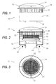
- Figure 1 illustrates a side or elevation view of a preferred embodiment of an exhaust flue cap and filter device 10 of the present invention.
- Figure 2 illustrates a sectional view cut through the center of the exhaust device 10 shown in Figure 1
- Figure 3 illustrates a top view of the exhaust flue cap and filter device 10 with the removable top taken off of the device for ease of viewing.
- Figure 4 illustrates an exploded view of the exhaust flue cap and filter device 10 separated from an exhaust flue vent system 12 with portions cut-away for clarity.
- the present invention operates with exhaust flue openings of various types and configurations.
- the exhaust flue cap and filter device 10 of the present invention may be utilized with a double wall exhaust system, such as a Type B double wall gas vent system which includes an outer cylindrical pipe 13 and a coaxial and concentric cylindrical liner 14 having a diameter smaller than the outer cylindrical pipe 13.
- the exhaust flue cap and filter device 10 includes a tubular cap 16 having a diameter larger than the outer pipe 13 so that at least a portion of the tubular cap 16 is receivable over the exhaust flue opening.
- the tubular cap 16 is cylindrical and concentric with the vent system 12.
- the tubular cap 16 as best seen in Figures 2 and 4 , includes an open lower end 18, an opposed open upper end 20, and a plurality of ventilation slots or vents 22 between the lower end 18 and the opposed upper end 20. Because the tubular cap 16 has an open lower end 18, atmospheric air is permitted to enter the tubular cap as shown by arrows 30 in Figure 2 .
- the tubular cap 16 may be fabricated from flat sheet metal or other lightweight material.
- the tubular cap 16 may be configured so that a cross-section of the chimney cap is in the form of an octagon, a hexagon, a square, a rectangle, an oval, a circle, or other configuration.
- the ventilation slots or vents 22 may be stamped or otherwise formed into the tubular cap 16.
- the ventilation slots or vents 22 may be in various patterns or configurations.
- a removable top 24 is attached to and closes the open upper end 20 of the tubular cap 16.
- the removable top 24 is shown attached to the device 10 in Figures 1 and 2 and is shown exploded from the device in Figure 4 .
- the removable top 24 may be secured by fasteners 26 or other mechanism to the tubular cap 16.
- the removable top 24 may likewise be fabricated from flat sheet metal or other lightweight material.
- the removable cap may include an outwardly extending rain flange 28.
- the outwardly extending rain flange 28 has a larger diameter than the removable top 24 and the tubular cap 16 and acts as an overhang to discourage rain or precipitation from entering the ventilation slots 22.
- a filter tray 40 is suspended within the tubular cap 16 and has a smaller diameter than the tubular cap 16.
- the filter tray 40 has an open bottom and an open top.
- the filter tray 40 includes a downwardly and outwardly extending flared skirt 42 which discourages rain and precipitation from entering the vent pipe and also encourages exhaust from the vent pipe to pass through the insert to be described.
- the filter tray 40 includes a ledge 44 extending radially inward.
- the ledge 44 acts as a support or shoulder to hold a removable filter insert 50.
- the filter tray 40 is substantially cylindrical.
- the filter insert 50 is substantially cylindrical with a slightly smaller diameter than the filter tray 40 so that the filter insert 50 is received into and is supported by the filter tray.
- the filter tray 40 may have a square cross-section (smaller than the cap 16) to accommodate a filter insert in the shape of a block.
- the filter tray 40 is be suspended within the tubular cap 16 by a series of stand-offs 52 as best seen in Figure 3 .
- the stand-offs 52 extend radially from the filter tray 40.
- the outwardly flared skirt 42 of the filter tray 40 encourages exhaust gases from the vent pipe 12 to pass through the filter insert 50.
- gases such as atmospheric air are permitted to enter the base of the tubular cap 16 and travel outside of the filter tray and filter insert 50 and pass above the filter tray and filter insert within the tubular cap.
- the atmospheric air assists in moving the exhaust gases up and through the tubular cap 16 and assists in catalytic conversion to be described. Also, in the event of blockage of the filter insert for any reason, both exhaust gases and atmospheric air may pass through the device without blockage.
- the exhaust flue cap and filter device 10 also includes a cylindrical inner collar 54 having a slightly larger diameter than the exhaust flue opening outer pipe 12 as best seen in Figure 4 . Accordingly, the inner collar 54 fits over the outer pipe 13 of the exhaust system.
- One or more stop tabs 48 may extend from the inner collar 54 to stop insertion of the inner collar once fully inserted.
- the inner collar 54 is suspended within the tubular cap 16 by a series of stand-offs 56 or by another mechanism.
- the exhaust flue cap and filter device 10 may be installed by slipping the inner collar 54 over the exhaust flue vent system 12 until the stop tabs 48 abut the upper edge of the outer pipe 13. Thereafter the device 10 is secured to the outer pipe 13 thereto with fasteners 58.
- the filter insert 50 may be removed and cleaned or may be replaced by removing the fasteners 26 in order to remove the removable top 24 from the tubular cap 16. Thereafter, it will be possible to access the filter insert 50 in order to remove it from the filter tray 40.
- a replacement filter insert may be installed in the tubular cap suspended by the filter tray 40.
- the filter insert 50 may be fabricated from a number of materials in order to reduce carbon monoxide and particulate emissions from the exhaust of the gas fired appliance.
- the filter insert 50 may be catalytically active in order to reduce carbon monoxide (CO) which escapes from the device 10.
- the catalytically active filter insert 50 may include a core or substrate and a washcoat including catalytically active metals.
- the filter insert reduces unburned hydrocarbons and carbon monoxide by oxidizing them over a metal catalyst. This catalyst aids the reaction of the carbon monoxide (CO) and hydrocarbons with the remaining oxygen in the exhaust gas and with oxygen in the atmospheric air entering the tubular cap 16. For example: 2CO + O 2 ⁇ 2CO 2
- the catalytically active converter may include a core or substrate material and a washcoat which is comprised of catalytically active metals.
- the washcoat is applied to the surface of the core or substrate material so that the washcoat comes into contact with exhaust gases passing from the gas fired appliance through the device 10.
- the removable filter insert 50 may be comprised of a number of materials.
- the filter insert 50 may be a wire screen or a series of wire screens with a washcoat including a precious metal catalyst.
- the wire screen may have twenty centimeter (eighth inch (1/8")) square, openings.
- the filter insert 50 may be comprised of a ceramic block monolith having a honeycomb structure with gas flow passages which are coated with a washcoat having a precious metal catalyst.
- the filter insert 50 is comprised of a metal foam with between three to five pores per inch.
- the filter insert includes a washcoat having a precious metal catalyst.
- the filter insert may take the form of multiple ceramic discs which are coated with a washcoat having a precious metal catalyst.
- the washcoat may be alumina based.
- exhaust gases are passed from a gas fired appliance (not shown) through the exhaust vent system 12 flue opening into the tubular cap 16 so that exhaust gases mix with atmospheric air entering the open lower end of the tubular cap 16.
- the atmospheric air and exhaust gases pass into and through the catalytic filter insert 50 in the tray.
- the exhaust gases are treated by the catalytically active filter insert 50 which promotes oxidation in order to convert excess carbon monoxide (CO) into carbon dioxide (CO 2 ).
- the treated gases are thereafter permitted to move from the upper end of the tubular cap 16 through the vents to the atmosphere.
- a further objective of the present invention is to minimize pressure loss through the device 10. In testing of the exhaust flue cap and filter device 10 of the present invention, only a minimal pressure drop was observed as exhaust gases passed from the flue exhaust through the device.
- Testing of the exhaust flue cap and filter device 10 of the present invention reveals a reduction of carbon monoxide emissions of from 20-40% but as high as 70% depending on operating conditions.
Landscapes
- Engineering & Computer Science (AREA)
- Chemical & Material Sciences (AREA)
- Environmental & Geological Engineering (AREA)
- Mechanical Engineering (AREA)
- General Engineering & Computer Science (AREA)
- Chemical Kinetics & Catalysis (AREA)
- Health & Medical Sciences (AREA)
- Biomedical Technology (AREA)
- Analytical Chemistry (AREA)
- General Chemical & Material Sciences (AREA)
- Oil, Petroleum & Natural Gas (AREA)
- Combustion & Propulsion (AREA)
- Filtering Of Dispersed Particles In Gases (AREA)
Description
- The present invention is directed to an exhaust flue cap and filter device or appliance and a method of use for an exhaust flue opening of a gas fired appliance. In particular, the present invention is directed to an exhaust flue cap and filter device which will reduce carbon monoxide and particulate emissions from the exhaust of a gas fired appliance.
- There are various types of known gas fired appliances that are used with buildings and residences. These include gas fired water heaters, gas fired boilers, gas fired fireplaces, gas logs fitted within fireplaces, gas fired air heating systems, gas fired clothes dryers, or other apparatus that use gaseous hydrocarbon fuels such as natural gas or propane.
- For the most part, gas fired appliances are relatively efficient and do not produce the extensive amount of soot or other emissions associated with wood burning fireplaces and stoves or with coal burning fireplaces or stoves. Even gas fired appliances, however, produce a certain amount of particulate emissions and carbon monoxide emissions.
- It is advisable and required by laws, codes, or regulations in many applications to vent a gas fired appliance from the building or residence outside to the atmosphere. There are various types and configurations of known venting systems. One type of double wall flue exhaust is known as a Type B double wall gas vent system. A Type B vent system includes an outer cylindrical wall along with a coaxial and concentric inner liner spaced from the outer wall.
- Venting system with filters are disclosed by the documents
DE 4 209 225 andDE 2 057 449 . - Accordingly, the present invention is directed to an exhaust flue cap and filter appliance as well as to a process using said appliance capable of reducing the carbon monoxide and particulate emissions from the exhaust of gas fired appliances.
- The present invention is directed to an exhaust flue cap and filter device for a gas fired appliance that can be installed with new building or residence construction or can be retro-fit to an existing flue opening.
- The present invention is directed to an exhaust flue cap and filter device for a gas fired appliance thatreduces carbon monoxide and particulate emissions through a removable and replaceable catalytic filter insert.
- The present invention is directed to an exhaust flue cap and filter device that will reduce carbon monoxide and particulate emissions while not substantially reducing flow through the exhaust flue.
- The present invention is directed to an exhaust flue cap and filter device that permits bypass of exhaust gases in the event of any blockage of the filter component of the device.
- The present invention is directed to an exhaust flue cap and filter device for a gas fired appliance according to claim 1 and to a process or method to reduce carbon monoxide and unburned hydrocarbon emissions from the exhaust of a gas fired appliance according to
claim 13. - The exhaust flue cap and filter device includes a tubular cap having a diameter larger than the exhaust flue opening. The tubular cap includes an open lower end, an opposed upper end, and a plurality of ventilation slots or vents between the lower end and the opposed upper end.
- A removable top is attached to and closes the open upper end of the tubular cap. The removable top may be secured by fasteners or other mechanism to the tubular cap. The removable top may also include an optional outwardly extending rain flange to discourage rain or precipitation from entering the ventilation slots of the tubular cap.
- A filter tray is suspended within the tubular cap and has a smaller diameter than the tubular cap. The filter tray is suspended within the tubular cap by a series of standoffs. The filter tray has an open bottom and an open top and may include a downwardly and outwardly extending flared skirt to discourage rain or precipitation from entering the exhaust vent pipe and also to encourage flue gas to pass through the filter tray.
- The filter tray includes a ledge extending radially inward to act as a support or shoulder to hold a removable filter insert which is received into the filter tray. The filter insert is catalytically active.
- The exhaust flue cap and filter device also includes a cylindrical inner collar having a slightly larger diameter than the exhaust flue opening so that the inner collar fits over the exhaust flue opening. The inner collar is suspended within the tubular cap such as by a series of standoffs or by another mechanism.
- In order to use the exhaust flue cap and filter device of the present invention, exhaust gases from the gas fired appliance are passed through the exhaust flue opening into the tubular cap. Atmospheric air is also allowed and permitted to pass into the tubular cap from the open lower end. The exhaust gases and the atmospheric air in the tubular cap are permitted to pass into and through the catalytic filter insert which is supported within the tubular cap. The exhaust gases are treated by the catalytic filter insert as they pass therethrough.
- The treated exhaust gases which have passed through the filter insert pass from the tubular cap through a plurality of ventilation holes in the tubular cap to the atmosphere.
-
-
Figure 1 illustrates a side view of an exhaust flue cap and filter device for a gas fired appliance exhaust flue opening constructed in accordance with the present invention; -
Figure 2 illustrates a sectional view cut through the center of the exhaust flue cap and filter device shown inFigure 1 ; -
Figure 3 illustrates a top view of the exhaust flue cap and filter device shown inFigure 1 apart from the exhaust flue opening; and -
Figure 4 illustrates an exploded view of the exhaust flue cap and filter device shown inFigures 1, 2 and 3 apart from the exhaust vent pipe flue opening. - Referring to the drawings in detail,
Figure 1 illustrates a side or elevation view of a preferred embodiment of an exhaust flue cap andfilter device 10 of the present invention.Figure 2 illustrates a sectional view cut through the center of theexhaust device 10 shown inFigure 1, and Figure 3 illustrates a top view of the exhaust flue cap andfilter device 10 with the removable top taken off of the device for ease of viewing. -
Figure 4 illustrates an exploded view of the exhaust flue cap andfilter device 10 separated from an exhaustflue vent system 12 with portions cut-away for clarity. - The present invention operates with exhaust flue openings of various types and configurations. As best seen in
Figures 1, 2 and4 , in one non-limiting embodiment, the exhaust flue cap andfilter device 10 of the present invention may be utilized with a double wall exhaust system, such as a Type B double wall gas vent system which includes an outercylindrical pipe 13 and a coaxial and concentriccylindrical liner 14 having a diameter smaller than the outercylindrical pipe 13. - As best seen in
Figure 2 , the exhaust flue cap andfilter device 10 includes atubular cap 16 having a diameter larger than theouter pipe 13 so that at least a portion of thetubular cap 16 is receivable over the exhaust flue opening. In the present embodiment, thetubular cap 16 is cylindrical and concentric with thevent system 12. - The
tubular cap 16, as best seen inFigures 2 and4 , includes an openlower end 18, an opposed openupper end 20, and a plurality of ventilation slots orvents 22 between thelower end 18 and the opposedupper end 20. Because thetubular cap 16 has an openlower end 18, atmospheric air is permitted to enter the tubular cap as shown byarrows 30 inFigure 2 . Thetubular cap 16 may be fabricated from flat sheet metal or other lightweight material. - The
tubular cap 16 may be configured so that a cross-section of the chimney cap is in the form of an octagon, a hexagon, a square, a rectangle, an oval, a circle, or other configuration. The ventilation slots orvents 22 may be stamped or otherwise formed into thetubular cap 16. The ventilation slots orvents 22 may be in various patterns or configurations. - A
removable top 24 is attached to and closes the openupper end 20 of thetubular cap 16. Theremovable top 24 is shown attached to thedevice 10 inFigures 1 and 2 and is shown exploded from the device inFigure 4 . Theremovable top 24 may be secured byfasteners 26 or other mechanism to thetubular cap 16. Theremovable top 24 may likewise be fabricated from flat sheet metal or other lightweight material. - The removable cap may include an outwardly extending
rain flange 28. The outwardly extendingrain flange 28 has a larger diameter than theremovable top 24 and thetubular cap 16 and acts as an overhang to discourage rain or precipitation from entering theventilation slots 22. - A
filter tray 40 is suspended within thetubular cap 16 and has a smaller diameter than thetubular cap 16. In one preferred embodiment, thefilter tray 40 has an open bottom and an open top. As may be appreciated fromFigures 2 and4 , thefilter tray 40 includes a downwardly and outwardly extending flaredskirt 42 which discourages rain and precipitation from entering the vent pipe and also encourages exhaust from the vent pipe to pass through the insert to be described. - The
filter tray 40 includes aledge 44 extending radially inward. Theledge 44 acts as a support or shoulder to hold aremovable filter insert 50. In one configuration, thefilter tray 40 is substantially cylindrical. Thefilter insert 50 is substantially cylindrical with a slightly smaller diameter than thefilter tray 40 so that thefilter insert 50 is received into and is supported by the filter tray. - In an alternate embodiment (not shown), the
filter tray 40 may have a square cross-section (smaller than the cap 16) to accommodate a filter insert in the shape of a block. - The
filter tray 40 is be suspended within thetubular cap 16 by a series of stand-offs 52 as best seen inFigure 3 . The stand-offs 52 extend radially from thefilter tray 40. The outwardly flaredskirt 42 of thefilter tray 40 encourages exhaust gases from thevent pipe 12 to pass through thefilter insert 50. - Because the
filter insert 50 and thefilter tray 40 have a diameter less than the tubular cap, gases such as atmospheric air are permitted to enter the base of thetubular cap 16 and travel outside of the filter tray and filterinsert 50 and pass above the filter tray and filter insert within the tubular cap. The atmospheric air assists in moving the exhaust gases up and through thetubular cap 16 and assists in catalytic conversion to be described. Also, in the event of blockage of the filter insert for any reason, both exhaust gases and atmospheric air may pass through the device without blockage. - The exhaust flue cap and
filter device 10 also includes a cylindricalinner collar 54 having a slightly larger diameter than the exhaust flue openingouter pipe 12 as best seen inFigure 4 . Accordingly, theinner collar 54 fits over theouter pipe 13 of the exhaust system. One or more stop tabs 48 (best seen inFigure 4 ) may extend from theinner collar 54 to stop insertion of the inner collar once fully inserted. Theinner collar 54 is suspended within thetubular cap 16 by a series of stand-offs 56 or by another mechanism. - The exhaust flue cap and
filter device 10 may be installed by slipping theinner collar 54 over the exhaustflue vent system 12 until thestop tabs 48 abut the upper edge of theouter pipe 13. Thereafter thedevice 10 is secured to theouter pipe 13 thereto withfasteners 58. - The
filter insert 50 may be removed and cleaned or may be replaced by removing thefasteners 26 in order to remove the removable top 24 from thetubular cap 16. Thereafter, it will be possible to access thefilter insert 50 in order to remove it from thefilter tray 40. A replacement filter insert may be installed in the tubular cap suspended by thefilter tray 40. - The
filter insert 50 may be fabricated from a number of materials in order to reduce carbon monoxide and particulate emissions from the exhaust of the gas fired appliance. - In one configuration, the
filter insert 50 may be catalytically active in order to reduce carbon monoxide (CO) which escapes from thedevice 10. The catalyticallyactive filter insert 50 may include a core or substrate and a washcoat including catalytically active metals. The filter insert reduces unburned hydrocarbons and carbon monoxide by oxidizing them over a metal catalyst. This catalyst aids the reaction of the carbon monoxide (CO) and hydrocarbons with the remaining oxygen in the exhaust gas and with oxygen in the atmospheric air entering thetubular cap 16. For example:
2CO + O2 ⇒ 2CO2
- The catalytically active converter may include a core or substrate material and a washcoat which is comprised of catalytically active metals. The washcoat is applied to the surface of the core or substrate material so that the washcoat comes into contact with exhaust gases passing from the gas fired appliance through the
device 10. - The
removable filter insert 50 may be comprised of a number of materials. In a first configuration, thefilter insert 50 may be a wire screen or a series of wire screens with a washcoat including a precious metal catalyst. In one non-limiting example, the wire screen may have twenty centimeter (eighth inch (1/8")) square, openings. - In a second embodiment, the
filter insert 50 may be comprised of a ceramic block monolith having a honeycomb structure with gas flow passages which are coated with a washcoat having a precious metal catalyst. - In a third embodiment, the
filter insert 50 is comprised of a metal foam with between three to five pores per inch. The filter insert includes a washcoat having a precious metal catalyst. - In a fourth configuration, the filter insert may take the form of multiple ceramic discs which are coated with a washcoat having a precious metal catalyst. In each case, the washcoat may be alumina based.
- In use, exhaust gases are passed from a gas fired appliance (not shown) through the
exhaust vent system 12 flue opening into thetubular cap 16 so that exhaust gases mix with atmospheric air entering the open lower end of thetubular cap 16. The atmospheric air and exhaust gases pass into and through thecatalytic filter insert 50 in the tray. The exhaust gases are treated by the catalyticallyactive filter insert 50 which promotes oxidation in order to convert excess carbon monoxide (CO) into carbon dioxide (CO2). The treated gases are thereafter permitted to move from the upper end of thetubular cap 16 through the vents to the atmosphere. - A further objective of the present invention is to minimize pressure loss through the
device 10. In testing of the exhaust flue cap andfilter device 10 of the present invention, only a minimal pressure drop was observed as exhaust gases passed from the flue exhaust through the device. - Testing of the exhaust flue cap and
filter device 10 of the present invention reveals a reduction of carbon monoxide emissions of from 20-40% but as high as 70% depending on operating conditions.
Claims (14)
- An exhaust flue cap and filter device (10) for a gas fired appliance in communication with an exhaust flue opening having an outer pipe (13) and a coaxial liner (14), which device comprises:a tubular cap (16) with an open lower end (18) for admission of atmospheric gases, an opposed open upper end (20), and a plurality of ventilation holes (22), said cap receivable over said exhaust flue opening;a filter tray (40) suspended in said tubular cap by a series of stand-offs (52), wherein said tray has a smaller diameter than an inner diameter of said tubular cap (16) and a ledge (44) extending radially inward from said tray; so that a bypass space is formed around said filter tray to permit passage of both exhaust gases and atmospheric air;a removable top (24) attached to and closing said open upper end (20) of said tubular cap (16);a removable filter insert (50), which is a catalytically active converter, receivable in said filter tray within said tubular cap (16) supported on said ledge (44); andan inner collar (54) to engage said exhaust flue opening outer pipe (13).
- An exhaust flue cap and filter device (10) as set forth in Claim 1 wherein said inner collar (54) includes at least one stop tab (48) which engages said exhaust flue opening.
- An exhaust flue cap and filter device ( 10) as set forth in Claim 1 wherein removable top (24) is attached to said tubular cap by fasteners (26).
- An exhaust flue cap and filter device (10) as set forth in Claim 1 wherein said tubular cap and said removable top (24) are each fabricated from flat sheet metal.
- An exhaust flue cap and filter device (10) as set forth in Claim 1 wherein said removable top (24) includes an outwardly extending rain flange (28).
- An exhaust flue cap and filter device (10) as set forth in Claim 1 wherein said tubular cap (16) has a cross-section from the group consisting of an octagon, a hexagon, a square, a rectangle, an oval, or a circle.
- An exhaust flue cap and filter device (10) as set forth in Claim 1 wherein said catalytically active converter includes a core or substrate and a washcoat including catalytically active metals.
- An exhaust flue cap and filter device (10) as set forth in Claim 7 wherein said core or substrate is a ceramic honeycomb structure with gas flow passages.
- An exhaust flue cap and filter device (10) as set forth in Claim 8 wherein said core or substrate is at least one wire screen.
- An exhaust flue cap and filter device (10) as set forth in Claim 8 wherein said core or substrate is a metal foam.
- An exhaust flue cap and filter device (10) as set forth in Claim 8 wherein said washcoat and catalyst are applied to a surface of said core or substrate.
- An exhaust flue cap and filter device (10) as set forth in Claim 1 wherein said filter tray (40) includes an outwardly flared skirt (42).
- A process to treat carbon monoxide and unburned hydrocarbon emissions from a gas fired appliance in communication with an exhaust flue opening, which process comprises:passing exhaust gases from said gas fired appliance through the exhaust flue opening into a tubular cap (16) with an open lower end (18), an opposed upper end (20), and a plurality of ventilation holes (22);permitting atmospheric air to pass into said tubular cap (16) through said open lower end (18);permitting said exhaust gases and said atmospheric air in said tubular cap (16) to pass into and through a catalytic filter insert (50) supported within said tubular cap (16) by a series of standoffs (52) wherein said filter insert has a smaller diameter than said tubular cap so that a bypass space is formed to permit passage of both exhaust gases and atmospheric air;treating said exhaust gases with said filter insert (50); andpermitting passage of said treated gases from within said removable top (24) through a plurality of ventilation holes (22) in said removable top.
- A process to treat emissions as set forth in Claim 13 wherein said filter insert (50) is a catalytic converter and wherein said step of treating emissions includes promoting oxidation with said catalytic converter.
Applications Claiming Priority (3)
| Application Number | Priority Date | Filing Date | Title |
|---|---|---|---|
| US97569307P | 2007-09-27 | 2007-09-27 | |
| US12/146,129 US8083574B2 (en) | 2007-09-27 | 2008-06-25 | Exhaust flue cap and filter device for a gas fired appliance |
| PCT/US2008/008883 WO2009042005A2 (en) | 2007-09-27 | 2008-07-22 | Exhaust flue cap and filter device for a gas fired appliance |
Publications (2)
| Publication Number | Publication Date |
|---|---|
| EP2195577A2 EP2195577A2 (en) | 2010-06-16 |
| EP2195577B1 true EP2195577B1 (en) | 2015-10-07 |
Family
ID=40508905
Family Applications (1)
| Application Number | Title | Priority Date | Filing Date |
|---|---|---|---|
| EP08794627.3A Active EP2195577B1 (en) | 2007-09-27 | 2008-07-22 | Exhaust flue cap and filter device for a gas fired appliance |
Country Status (4)
| Country | Link |
|---|---|
| US (1) | US8083574B2 (en) |
| EP (1) | EP2195577B1 (en) |
| CA (1) | CA2700600C (en) |
| WO (1) | WO2009042005A2 (en) |
Families Citing this family (18)
| Publication number | Priority date | Publication date | Assignee | Title |
|---|---|---|---|---|
| US9057519B1 (en) * | 2007-07-17 | 2015-06-16 | Improved Consumer Products, Inc. | Chimney cap |
| NZ569850A (en) * | 2008-07-16 | 2011-03-31 | Herville Neville Donald D | Chimney cover with diffuser and sleeve sides enclosing expansion area |
| US8664781B2 (en) * | 2010-04-15 | 2014-03-04 | Mujeeb Ur Rehman Alvi | Tunnel power turbine system to generate potential energy from waste kinetic energy |
| US8574045B2 (en) * | 2010-12-17 | 2013-11-05 | Dina Warner | Frost-free vent assembly |
| US9623506B2 (en) | 2011-02-01 | 2017-04-18 | Illinois Tool Works Inc. | Fume extractor for welding applications |
| US10690343B2 (en) * | 2011-08-01 | 2020-06-23 | Top Hat Chimney Systems, Inc. | Universal chimney pipe cover |
| US9821351B2 (en) | 2011-11-11 | 2017-11-21 | Illinois Tool Works Inc. | Welding fume extractor |
| US9604266B2 (en) | 2012-03-16 | 2017-03-28 | Illinois Tool Works Inc. | Airborne component extractor manifold |
| US10663192B2 (en) * | 2013-01-04 | 2020-05-26 | Fleming Vaughn Carroll | Vertical vent stack cap |
| US9839948B2 (en) * | 2013-01-29 | 2017-12-12 | Illinois Tool Works Inc. | Fume evacuation system |
| US10808953B2 (en) | 2013-06-28 | 2020-10-20 | Illinois Tool Works Inc. | Airborne component extractor with baffled debris collection |
| US10465930B2 (en) * | 2014-03-06 | 2019-11-05 | Gregory S. Daniels | Roof vent with an integrated fan |
| US11014132B2 (en) | 2015-07-16 | 2021-05-25 | Illinois Tool Works Inc. | Extractor with end-mounted positive pressure system |
| US11530826B2 (en) | 2015-07-16 | 2022-12-20 | Illinois Tool Works Inc. | Extractor with segmented positive pressure airflow system |
| US10295183B2 (en) * | 2016-05-10 | 2019-05-21 | Alice Rachel Bangera | Wind boosted ventilators having openings and compartments |
| US10571139B1 (en) * | 2018-04-27 | 2020-02-25 | Windsmart, Llc | Modular vent for removing entrapped moisture with wind |
| CN109126237A (en) * | 2018-09-12 | 2019-01-04 | 徐赫 | Stainless steel filter head |
| CN113531537A (en) * | 2020-04-20 | 2021-10-22 | 宋钰婷 | Air environment-friendly waste incineration device with flue gas washing and purifying functions |
Family Cites Families (31)
| Publication number | Priority date | Publication date | Assignee | Title |
|---|---|---|---|---|
| US2803184A (en) * | 1952-05-19 | 1957-08-20 | Wasserman Max | Ventilator cover |
| NL285638A (en) | 1961-11-20 | |||
| US3441381A (en) | 1965-06-22 | 1969-04-29 | Engelhard Ind Inc | Apparatus for purifying exhaust gases of an internal combustion engine |
| US3361051A (en) * | 1966-03-28 | 1968-01-02 | Motor Wheel Corp | Vent cap assembly |
| DE2057449A1 (en) | 1970-11-23 | 1972-06-08 | Schellworth Karl Heinz | Method and device for increasing and achieving constant draft in chimneys |
| DE2220023A1 (en) | 1972-04-24 | 1973-11-08 | Helmut Schlegl | ABSORBER USE FOR FIREPLACES |
| US3885977A (en) | 1973-11-05 | 1975-05-27 | Corning Glass Works | Anisotropic cordierite monolith |
| US4147096A (en) * | 1977-06-01 | 1979-04-03 | Dresser Industries, Inc. | Breather vent for vapor vent valve |
| US4138220A (en) * | 1978-02-13 | 1979-02-06 | Colonial Metals, Inc. | Apparatus for catalytic oxidation of grease and fats in low temperature fumes |
| US4397225A (en) * | 1981-06-25 | 1983-08-09 | Perform, Inc. | Stack draft stabilizing device |
| US4399743A (en) * | 1981-10-15 | 1983-08-23 | Plastic Oddities, Inc. | Vent pipe cap |
| US4476852A (en) * | 1982-12-06 | 1984-10-16 | Lee Jonathan P | Add-on catalytic damper assembly |
| US4582044A (en) * | 1984-01-19 | 1986-04-15 | Vermont Castings, Inc. | Clean burning exterior retrofit system for solid fuel heating appliances |
| JPS60155822A (en) | 1984-01-25 | 1985-08-15 | Matsushita Electric Works Ltd | Exhaust cylinder top |
| DE8405331U1 (en) | 1984-02-22 | 1984-05-17 | Dipl.-Ing. H.-R. Scholz Industrievertretungsgesellschaft mbH, 8070 Ingolstadt | CATALYST SYSTEM FOR THE DETERGENT DETOXIFICATION OF DOMESTIC OVENS |
| US4593504A (en) * | 1985-02-14 | 1986-06-10 | Jimco Products | Pressure equalizing roof vent |
| DE3818937A1 (en) | 1987-12-01 | 1989-12-14 | Hugo Paril | ATTACHMENT FOR FIREPLACES |
| US4889160A (en) * | 1988-12-28 | 1989-12-26 | Sheets Johnny S | Antitamper vent arrangement for a receptacle or enclosure |
| GB9027331D0 (en) * | 1990-12-18 | 1991-02-06 | Ici Plc | Catalytic combustion |
| DE4209225C2 (en) | 1992-03-21 | 1994-05-26 | Loebbert Franz Josef | Flue gas cleaning attachment with modular filter system for chimneys of small fire systems |
| US5749780A (en) * | 1996-09-05 | 1998-05-12 | Icopa A/S | Roof vent |
| US6022269A (en) | 1999-04-27 | 2000-02-08 | Christopher Arbucci | Stackable chimney cap |
| US20020104528A1 (en) | 1999-12-10 | 2002-08-08 | Staller Tracy D. | Catalytic gas heater screen system |
| US6805627B2 (en) * | 2001-11-30 | 2004-10-19 | Arc3 Corporation | Security cover for ventilation duct |
| USD503471S1 (en) | 2003-11-12 | 2005-03-29 | Robert M. Huta | Cap for gas appliance vent |
| US7275929B2 (en) | 2003-12-22 | 2007-10-02 | Tiegs Paul E | Device and method for reducing fireplace particulate emissions |
| KR101270180B1 (en) * | 2004-01-30 | 2013-05-31 | 가부시키가이샤 한도오따이 에네루기 켄큐쇼 | An inspection apparatus, inspenction method, and method for manufacturing a semiconductor device |
| US6978803B2 (en) * | 2004-02-04 | 2005-12-27 | K&M Plastics, Llc | Flue cap |
| US6926600B1 (en) | 2004-05-17 | 2005-08-09 | European Copper, Llc | Chimney cap apparatus and method |
| US7179164B2 (en) | 2004-05-17 | 2007-02-20 | European Copper, L.L.C. | Chimney cap apparatus and method |
| USD535010S1 (en) | 2004-05-17 | 2007-01-09 | European Copper, L.L.C. | Chimney cap |
-
2008
- 2008-06-25 US US12/146,129 patent/US8083574B2/en active Active
- 2008-07-22 EP EP08794627.3A patent/EP2195577B1/en active Active
- 2008-07-22 WO PCT/US2008/008883 patent/WO2009042005A2/en active Application Filing
- 2008-07-22 CA CA2700600A patent/CA2700600C/en active Active
Also Published As
| Publication number | Publication date |
|---|---|
| WO2009042005A3 (en) | 2010-03-18 |
| WO2009042005A2 (en) | 2009-04-02 |
| CA2700600C (en) | 2015-07-07 |
| CA2700600A1 (en) | 2009-04-02 |
| EP2195577A2 (en) | 2010-06-16 |
| US20090088060A1 (en) | 2009-04-02 |
| US8083574B2 (en) | 2011-12-27 |
Similar Documents
| Publication | Publication Date | Title |
|---|---|---|
| EP2195577B1 (en) | Exhaust flue cap and filter device for a gas fired appliance | |
| CA1196323A (en) | Combustion catalyst bed | |
| US4054418A (en) | Catalytic abatement system | |
| CA1196324A (en) | Catalytic combustor | |
| WO2004048852A8 (en) | Method for treating emissions | |
| US20130052094A1 (en) | Device for treating exhaust gases from a small heating system | |
| US20150075510A1 (en) | Catalytic unit for solid fuel burning stoves | |
| EP2418425B1 (en) | Device for treating exhaust gases from a small heating system | |
| EP2165118B1 (en) | Chimney cap with replaceable or recyclable ceramic catalytic filter insert | |
| WO2015051911A1 (en) | Fireplace | |
| US9863634B1 (en) | Exhaust flue cap and filter device for a gas fired appliance | |
| US10646824B2 (en) | Catalytic cookstove with passive control of draft and method of use | |
| US20020104528A1 (en) | Catalytic gas heater screen system | |
| EP3470738A1 (en) | Solid fuel stove | |
| JPH11132423A (en) | Re-combusting and thermal cracking furnace for exhaust gas | |
| US7566423B2 (en) | Air purification system employing particle burning | |
| US6578531B1 (en) | Gas appliance with flash suppressor | |
| DE102013020398A1 (en) | Combustion chamber installed in e.g. chimney oven, has active high temperature stable assembly which is provided with support portion in which catalytically active substance is coated for reduction of pollutant emissions | |
| EP0087259A1 (en) | Combustor device for a solid fuel heating appliance | |
| CA1202539A (en) | Wood burning stove | |
| SU1024658A1 (en) | Thermal catalytic apparatus for cleaning gas effluents |
Legal Events
| Date | Code | Title | Description |
|---|---|---|---|
| PUAI | Public reference made under article 153(3) epc to a published international application that has entered the european phase |
Free format text: ORIGINAL CODE: 0009012 |
|
| 17P | Request for examination filed |
Effective date: 20100326 |
|
| AK | Designated contracting states |
Kind code of ref document: A2 Designated state(s): AT BE BG CH CY CZ DE DK EE ES FI FR GB GR HR HU IE IS IT LI LT LU LV MC MT NL NO PL PT RO SE SI SK TR |
|
| AX | Request for extension of the european patent |
Extension state: AL BA MK RS |
|
| DAX | Request for extension of the european patent (deleted) | ||
| 17Q | First examination report despatched |
Effective date: 20130621 |
|
| REG | Reference to a national code |
Ref country code: DE Ref legal event code: R079 Ref document number: 602008040555 Country of ref document: DE Free format text: PREVIOUS MAIN CLASS: F23G0007070000 Ipc: B01D0053860000 |
|
| RIC1 | Information provided on ipc code assigned before grant |
Ipc: B01D 53/88 20060101ALI20150119BHEP Ipc: F23J 15/02 20060101ALI20150119BHEP Ipc: F23G 7/07 20060101ALI20150119BHEP Ipc: F23L 17/02 20060101ALI20150119BHEP Ipc: B01D 53/86 20060101AFI20150119BHEP |
|
| GRAP | Despatch of communication of intention to grant a patent |
Free format text: ORIGINAL CODE: EPIDOSNIGR1 |
|
| INTG | Intention to grant announced |
Effective date: 20150326 |
|
| RIN1 | Information on inventor provided before grant (corrected) |
Inventor name: SMITH, JOSEPH D. |
|
| GRAS | Grant fee paid |
Free format text: ORIGINAL CODE: EPIDOSNIGR3 |
|
| GRAA | (expected) grant |
Free format text: ORIGINAL CODE: 0009210 |
|
| AK | Designated contracting states |
Kind code of ref document: B1 Designated state(s): AT BE BG CH CY CZ DE DK EE ES FI FR GB GR HR HU IE IS IT LI LT LU LV MC MT NL NO PL PT RO SE SI SK TR |
|
| REG | Reference to a national code |
Ref country code: GB Ref legal event code: FG4D |
|
| REG | Reference to a national code |
Ref country code: AT Ref legal event code: REF Ref document number: 753387 Country of ref document: AT Kind code of ref document: T Effective date: 20151015 Ref country code: CH Ref legal event code: EP |
|
| REG | Reference to a national code |
Ref country code: IE Ref legal event code: FG4D |
|
| REG | Reference to a national code |
Ref country code: DE Ref legal event code: R096 Ref document number: 602008040555 Country of ref document: DE |
|
| REG | Reference to a national code |
Ref country code: NL Ref legal event code: MP Effective date: 20151007 |
|
| REG | Reference to a national code |
Ref country code: AT Ref legal event code: MK05 Ref document number: 753387 Country of ref document: AT Kind code of ref document: T Effective date: 20151007 |
|
| REG | Reference to a national code |
Ref country code: LT Ref legal event code: MG4D |
|
| PG25 | Lapsed in a contracting state [announced via postgrant information from national office to epo] |
Ref country code: ES Free format text: LAPSE BECAUSE OF FAILURE TO SUBMIT A TRANSLATION OF THE DESCRIPTION OR TO PAY THE FEE WITHIN THE PRESCRIBED TIME-LIMIT Effective date: 20151007 Ref country code: IT Free format text: LAPSE BECAUSE OF FAILURE TO SUBMIT A TRANSLATION OF THE DESCRIPTION OR TO PAY THE FEE WITHIN THE PRESCRIBED TIME-LIMIT Effective date: 20151007 Ref country code: HR Free format text: LAPSE BECAUSE OF FAILURE TO SUBMIT A TRANSLATION OF THE DESCRIPTION OR TO PAY THE FEE WITHIN THE PRESCRIBED TIME-LIMIT Effective date: 20151007 Ref country code: IS Free format text: LAPSE BECAUSE OF FAILURE TO SUBMIT A TRANSLATION OF THE DESCRIPTION OR TO PAY THE FEE WITHIN THE PRESCRIBED TIME-LIMIT Effective date: 20160207 Ref country code: NO Free format text: LAPSE BECAUSE OF FAILURE TO SUBMIT A TRANSLATION OF THE DESCRIPTION OR TO PAY THE FEE WITHIN THE PRESCRIBED TIME-LIMIT Effective date: 20160107 Ref country code: NL Free format text: LAPSE BECAUSE OF FAILURE TO SUBMIT A TRANSLATION OF THE DESCRIPTION OR TO PAY THE FEE WITHIN THE PRESCRIBED TIME-LIMIT Effective date: 20151007 Ref country code: LT Free format text: LAPSE BECAUSE OF FAILURE TO SUBMIT A TRANSLATION OF THE DESCRIPTION OR TO PAY THE FEE WITHIN THE PRESCRIBED TIME-LIMIT Effective date: 20151007 |
|
| PG25 | Lapsed in a contracting state [announced via postgrant information from national office to epo] |
Ref country code: PL Free format text: LAPSE BECAUSE OF FAILURE TO SUBMIT A TRANSLATION OF THE DESCRIPTION OR TO PAY THE FEE WITHIN THE PRESCRIBED TIME-LIMIT Effective date: 20151007 Ref country code: AT Free format text: LAPSE BECAUSE OF FAILURE TO SUBMIT A TRANSLATION OF THE DESCRIPTION OR TO PAY THE FEE WITHIN THE PRESCRIBED TIME-LIMIT Effective date: 20151007 Ref country code: FI Free format text: LAPSE BECAUSE OF FAILURE TO SUBMIT A TRANSLATION OF THE DESCRIPTION OR TO PAY THE FEE WITHIN THE PRESCRIBED TIME-LIMIT Effective date: 20151007 Ref country code: GR Free format text: LAPSE BECAUSE OF FAILURE TO SUBMIT A TRANSLATION OF THE DESCRIPTION OR TO PAY THE FEE WITHIN THE PRESCRIBED TIME-LIMIT Effective date: 20160108 Ref country code: PT Free format text: LAPSE BECAUSE OF FAILURE TO SUBMIT A TRANSLATION OF THE DESCRIPTION OR TO PAY THE FEE WITHIN THE PRESCRIBED TIME-LIMIT Effective date: 20160208 Ref country code: LV Free format text: LAPSE BECAUSE OF FAILURE TO SUBMIT A TRANSLATION OF THE DESCRIPTION OR TO PAY THE FEE WITHIN THE PRESCRIBED TIME-LIMIT Effective date: 20151007 Ref country code: SE Free format text: LAPSE BECAUSE OF FAILURE TO SUBMIT A TRANSLATION OF THE DESCRIPTION OR TO PAY THE FEE WITHIN THE PRESCRIBED TIME-LIMIT Effective date: 20151007 |
|
| REG | Reference to a national code |
Ref country code: DE Ref legal event code: R097 Ref document number: 602008040555 Country of ref document: DE |
|
| PG25 | Lapsed in a contracting state [announced via postgrant information from national office to epo] |
Ref country code: CZ Free format text: LAPSE BECAUSE OF FAILURE TO SUBMIT A TRANSLATION OF THE DESCRIPTION OR TO PAY THE FEE WITHIN THE PRESCRIBED TIME-LIMIT Effective date: 20151007 |
|
| REG | Reference to a national code |
Ref country code: FR Ref legal event code: PLFP Year of fee payment: 9 |
|
| PLBE | No opposition filed within time limit |
Free format text: ORIGINAL CODE: 0009261 |
|
| STAA | Information on the status of an ep patent application or granted ep patent |
Free format text: STATUS: NO OPPOSITION FILED WITHIN TIME LIMIT |
|
| PG25 | Lapsed in a contracting state [announced via postgrant information from national office to epo] |
Ref country code: DK Free format text: LAPSE BECAUSE OF FAILURE TO SUBMIT A TRANSLATION OF THE DESCRIPTION OR TO PAY THE FEE WITHIN THE PRESCRIBED TIME-LIMIT Effective date: 20151007 Ref country code: RO Free format text: LAPSE BECAUSE OF FAILURE TO SUBMIT A TRANSLATION OF THE DESCRIPTION OR TO PAY THE FEE WITHIN THE PRESCRIBED TIME-LIMIT Effective date: 20151007 Ref country code: EE Free format text: LAPSE BECAUSE OF FAILURE TO SUBMIT A TRANSLATION OF THE DESCRIPTION OR TO PAY THE FEE WITHIN THE PRESCRIBED TIME-LIMIT Effective date: 20151007 Ref country code: SK Free format text: LAPSE BECAUSE OF FAILURE TO SUBMIT A TRANSLATION OF THE DESCRIPTION OR TO PAY THE FEE WITHIN THE PRESCRIBED TIME-LIMIT Effective date: 20151007 |
|
| 26N | No opposition filed |
Effective date: 20160708 |
|
| PG25 | Lapsed in a contracting state [announced via postgrant information from national office to epo] |
Ref country code: SI Free format text: LAPSE BECAUSE OF FAILURE TO SUBMIT A TRANSLATION OF THE DESCRIPTION OR TO PAY THE FEE WITHIN THE PRESCRIBED TIME-LIMIT Effective date: 20151007 |
|
| PG25 | Lapsed in a contracting state [announced via postgrant information from national office to epo] |
Ref country code: BE Free format text: LAPSE BECAUSE OF FAILURE TO SUBMIT A TRANSLATION OF THE DESCRIPTION OR TO PAY THE FEE WITHIN THE PRESCRIBED TIME-LIMIT Effective date: 20151007 |
|
| REG | Reference to a national code |
Ref country code: CH Ref legal event code: PL |
|
| PG25 | Lapsed in a contracting state [announced via postgrant information from national office to epo] |
Ref country code: MC Free format text: LAPSE BECAUSE OF FAILURE TO SUBMIT A TRANSLATION OF THE DESCRIPTION OR TO PAY THE FEE WITHIN THE PRESCRIBED TIME-LIMIT Effective date: 20151007 |
|
| PG25 | Lapsed in a contracting state [announced via postgrant information from national office to epo] |
Ref country code: LI Free format text: LAPSE BECAUSE OF NON-PAYMENT OF DUE FEES Effective date: 20160731 Ref country code: CH Free format text: LAPSE BECAUSE OF NON-PAYMENT OF DUE FEES Effective date: 20160731 |
|
| REG | Reference to a national code |
Ref country code: FR Ref legal event code: PLFP Year of fee payment: 10 |
|
| PG25 | Lapsed in a contracting state [announced via postgrant information from national office to epo] |
Ref country code: LU Free format text: LAPSE BECAUSE OF NON-PAYMENT OF DUE FEES Effective date: 20160722 |
|
| PG25 | Lapsed in a contracting state [announced via postgrant information from national office to epo] |
Ref country code: CY Free format text: LAPSE BECAUSE OF FAILURE TO SUBMIT A TRANSLATION OF THE DESCRIPTION OR TO PAY THE FEE WITHIN THE PRESCRIBED TIME-LIMIT Effective date: 20151007 Ref country code: HU Free format text: LAPSE BECAUSE OF FAILURE TO SUBMIT A TRANSLATION OF THE DESCRIPTION OR TO PAY THE FEE WITHIN THE PRESCRIBED TIME-LIMIT; INVALID AB INITIO Effective date: 20080722 |
|
| PG25 | Lapsed in a contracting state [announced via postgrant information from national office to epo] |
Ref country code: TR Free format text: LAPSE BECAUSE OF FAILURE TO SUBMIT A TRANSLATION OF THE DESCRIPTION OR TO PAY THE FEE WITHIN THE PRESCRIBED TIME-LIMIT Effective date: 20151007 Ref country code: MT Free format text: LAPSE BECAUSE OF NON-PAYMENT OF DUE FEES Effective date: 20160731 |
|
| REG | Reference to a national code |
Ref country code: FR Ref legal event code: PLFP Year of fee payment: 11 |
|
| PG25 | Lapsed in a contracting state [announced via postgrant information from national office to epo] |
Ref country code: BG Free format text: LAPSE BECAUSE OF FAILURE TO SUBMIT A TRANSLATION OF THE DESCRIPTION OR TO PAY THE FEE WITHIN THE PRESCRIBED TIME-LIMIT Effective date: 20151007 |
|
| P01 | Opt-out of the competence of the unified patent court (upc) registered |
Effective date: 20230526 |
|
| PGFP | Annual fee paid to national office [announced via postgrant information from national office to epo] |
Ref country code: IE Payment date: 20230621 Year of fee payment: 16 |
|
| PGFP | Annual fee paid to national office [announced via postgrant information from national office to epo] |
Ref country code: GB Payment date: 20230729 Year of fee payment: 16 |
|
| PGFP | Annual fee paid to national office [announced via postgrant information from national office to epo] |
Ref country code: FR Payment date: 20230725 Year of fee payment: 16 Ref country code: DE Payment date: 20230630 Year of fee payment: 16 |