EP2195500B1 - Door latch with fast unlock - Google Patents
Door latch with fast unlock Download PDFInfo
- Publication number
- EP2195500B1 EP2195500B1 EP08837202.4A EP08837202A EP2195500B1 EP 2195500 B1 EP2195500 B1 EP 2195500B1 EP 08837202 A EP08837202 A EP 08837202A EP 2195500 B1 EP2195500 B1 EP 2195500B1
- Authority
- EP
- European Patent Office
- Prior art keywords
- lock
- lever
- lock lever
- door
- door release
- Prior art date
- Legal status (The legal status is an assumption and is not a legal conclusion. Google has not performed a legal analysis and makes no representation as to the accuracy of the status listed.)
- Not-in-force
Links
Images

Classifications
-
- E—FIXED CONSTRUCTIONS
- E05—LOCKS; KEYS; WINDOW OR DOOR FITTINGS; SAFES
- E05B—LOCKS; ACCESSORIES THEREFOR; HANDCUFFS
- E05B85/00—Details of vehicle locks not provided for in groups E05B77/00 - E05B83/00
- E05B85/01—Mechanical arrangements specially adapted for hands-free locking or unlocking
-
- E—FIXED CONSTRUCTIONS
- E05—LOCKS; KEYS; WINDOW OR DOOR FITTINGS; SAFES
- E05B—LOCKS; ACCESSORIES THEREFOR; HANDCUFFS
- E05B81/00—Power-actuated vehicle locks
- E05B81/02—Power-actuated vehicle locks characterised by the type of actuators used
- E05B81/04—Electrical
- E05B81/06—Electrical using rotary motors
-
- E—FIXED CONSTRUCTIONS
- E05—LOCKS; KEYS; WINDOW OR DOOR FITTINGS; SAFES
- E05B—LOCKS; ACCESSORIES THEREFOR; HANDCUFFS
- E05B81/00—Power-actuated vehicle locks
- E05B81/12—Power-actuated vehicle locks characterised by the function or purpose of the powered actuators
- E05B81/16—Power-actuated vehicle locks characterised by the function or purpose of the powered actuators operating on locking elements for locking or unlocking action
-
- E—FIXED CONSTRUCTIONS
- E05—LOCKS; KEYS; WINDOW OR DOOR FITTINGS; SAFES
- E05B—LOCKS; ACCESSORIES THEREFOR; HANDCUFFS
- E05B81/00—Power-actuated vehicle locks
- E05B81/24—Power-actuated vehicle locks characterised by constructional features of the actuator or the power transmission
- E05B81/32—Details of the actuator transmission
- E05B81/34—Details of the actuator transmission of geared transmissions
-
- E—FIXED CONSTRUCTIONS
- E05—LOCKS; KEYS; WINDOW OR DOOR FITTINGS; SAFES
- E05B—LOCKS; ACCESSORIES THEREFOR; HANDCUFFS
- E05B15/00—Other details of locks; Parts for engagement by bolts of fastening devices
- E05B15/004—Lost motion connections
-
- Y—GENERAL TAGGING OF NEW TECHNOLOGICAL DEVELOPMENTS; GENERAL TAGGING OF CROSS-SECTIONAL TECHNOLOGIES SPANNING OVER SEVERAL SECTIONS OF THE IPC; TECHNICAL SUBJECTS COVERED BY FORMER USPC CROSS-REFERENCE ART COLLECTIONS [XRACs] AND DIGESTS
- Y10—TECHNICAL SUBJECTS COVERED BY FORMER USPC
- Y10T—TECHNICAL SUBJECTS COVERED BY FORMER US CLASSIFICATION
- Y10T292/00—Closure fasteners
- Y10T292/08—Bolts
- Y10T292/1043—Swinging
- Y10T292/1075—Operating means
- Y10T292/1076—Link and lever
-
- Y—GENERAL TAGGING OF NEW TECHNOLOGICAL DEVELOPMENTS; GENERAL TAGGING OF CROSS-SECTIONAL TECHNOLOGIES SPANNING OVER SEVERAL SECTIONS OF THE IPC; TECHNICAL SUBJECTS COVERED BY FORMER USPC CROSS-REFERENCE ART COLLECTIONS [XRACs] AND DIGESTS
- Y10—TECHNICAL SUBJECTS COVERED BY FORMER USPC
- Y10T—TECHNICAL SUBJECTS COVERED BY FORMER US CLASSIFICATION
- Y10T292/00—Closure fasteners
- Y10T292/08—Bolts
- Y10T292/1043—Swinging
- Y10T292/1075—Operating means
- Y10T292/108—Lever
Definitions
- the present invention relates to a closure latch for a vehicle door, and more particularly to a closure latch for a vehicle door equipped with a passive entry feature.
- Passive entry systems for vehicles are provided on some vehicles to permit a vehicle user who is in possession of the vehicle key to simply pull the door handle and open the door without the need to introduce the key into a keyhole in the door.
- the key (more particularly, the key fob) is equipped with an electronic device that communicates with the vehicle's on-board control system to authenticate the user.
- the vehicle's on-board control system to authenticate the user.
- Document US 2003/074935 A1 discloses a door-locking device having an inside door-handle element which can be moved from a closed position into an open position by virtue of an inside door handle being actuated. Also provided is an outside door-handle element which can be moved from a closed position into an open position by virtue of an outside door handle being actuated.
- a driver element can be coupled in a form-fitting manner to the inside door-handle element and the outside door-handle element by a coupling and can be moved from an uncoupled closed position into a coupled open position by the inside door-handle element and the outside door-handle element.
- a catch of a door lock can be actuated, it being the case that the coupling can be moved counter to a spring force from its coupled position into its uncoupled position by an uncoupling element.
- the invention is directed to a closure latch according to claim 1 for a vehicle door.
- FIGS. 1 a and 1 b show portions of a closure latch 10 for a door (not shown) of a vehicle (not shown), in accordance with an embodiment of the present invention.
- the closure latch 10 includes a ratchet 12 ( Figure 1 b) , a pawl 14 ( Figure 1b ), a first door release lever 16 ( Figure 1c ), a second door release lever 18 ( Figure 1 b) , a lock link 20 ( Figure 1 b) , a lock lever 22 ( Figure 1 a) , a lock lever actuator 24 ( Figure 1 a) and a lock knob assembly 25 (a small portion of which is shown in Figure 1 a) .
- the ratchet 12 is movable between a closed position ( Figure 1 b) wherein the ratchet 12 retains a striker (not shown) mounted on the body (not shown) of the vehicle and an open position wherein the ratchet 12 is unengaged with the striker.
- a ratchet biasing member 26 such as a suitable spring may be provided to bias the ratchet 12 towards the open position.
- the pawl 14 is movable between a ratchet locking position ( Figure 1 b) wherein the pawl 14 holds the ratchet 12 in the closed position, and a release position wherein the pawl 14 permits the ratchet 12 to move to its open position.
- a pawl biasing member 28 such as a suitable spring may be provided to bias the pawl 14 towards the ratchet locking position.
- the first door release lever 16 is operatively connected to the ratchet 12 for movement from the closed position to the open position.
- the first door release lever 16 may be operatively connected to the ratchet 12 in any suitable way, such as by direct mechanical engagement (See Figure 1 e) .
- the first door release lever 16 may be movable from a rest position to a door release position (not shown) wherein it moves the pawl 14 to the release position (not shown) so that the ratchet 12 can be moved from the closed position to the open position under the urging of the ratchet biasing member 26.
- a first door release lever biasing member 30, such as a suitable spring, may be provided to bias the first door release lever 16 towards its rest position.
- a first door release lever biasing member 30 that is dedicated solely to moving the first door release lever 16 to its rest position, it is possible for the pawl 14 to move the first door release lever 16 to its rest position, during movement of the pawl 14 to its ratchet locking position under the urging of the pawl biasing member 28.
- the pawl biasing member 28 may act as a first door release lever biasing member 30 as shown in Figure 1b .
- the first door release lever 16 ( Figure 1c ) has a first lock link engagement surface 32 which is configured to be engaged by the lock link 20.
- the second door release lever 18 ( Figure 2c ) is operatively connectable to the first door release lever 16.
- the second door release lever 18 may be operatively connectable to the first door release lever 16 in any suitable way, such as through the lock link 20.
- the second door release lever 18 includes a second lock link engagement surface 34 that is positioned to engage the lock link 20.
- the second door release lever 18 may be movable from a rest position ( Figure 1 c) to a door release position (not shown), which is described further below.
- a second door release lever biasing member 36 such as a suitable spring, may be provided to bias the second door release lever 18 towards its rest position.
- the second door release lever 18 may be moved from its rest position to its door release position by one or more means, such as by movement of an outer door handle (not shown) on the outside of the vehicle door (not shown).
- the lock link 20 may be movable between a first lock link position 20 ( Figures 1a-1e ) wherein the lock link 20 is disengaged from the first door release lever, and a second lock link position ( Figures 2a-2e ) wherein the second door release lever 18 is operatively connected to the first door release lever 16 through the lock link 20. More specifically, when a person pulls the outside door handle the second door release lever 18 is moved from its rest position to its door release position and moves a first end 38 of the lock link 20 with it.
- the lock link 20 may be biased towards the second lock link position ( Figure 2b ), by any suitable means, such as by a suitable spring 41.
- the second end of the lock link 20 is shown at 40 in Figure 1 a.
- the lock link 20 has a guide pin 42 and a lock lever engagement member 44.
- the guide pin 42 engages a guide channel 46 that is fixedly connected to a latch housing member 48.
- the guide channel 46 and the guide pin 42 together guide the movement of the lock link 20 between its first and second positions.
- the guide pin 42 is rotatable within the guide channel 46 ( Figure 1b ). This permits the lock link 20 to pivot as necessary during movement of the second door release lever 18 between its rest position and its door release position.
- the lock lever engagement member 44 is engageable by the lock lever 22 ( Figure 1 a) .
- the lock lever 22 is movable between a first position ( Figure 1 a) , a second position ( Figure 2a ) and a third position ( Figure 3 ). In the first position, the lock lever 22 holds the lock link 20 in the first lock link position ( Figures 1a-1e ). Additionally, when the lock lever 22 is in the first position, the lock knob assembly 25 is in a locked lock knob assembly position.
- lock lever 22 When the lock lever 22 is in the second position ( Figure 2a ), it permits the lock link 20 to move to the second lock link position ( Figure 2b ) under the urging of the lock link biasing member 41 ( Figure 2b ), thereby providing an operative connection from the second door release lever 18 to the first door release lever 16. Additionally, when the lock lever 22 is in the second position, the lock knob assembly 25 may be moved from the locked lock knob assembly position to an intermediate position ( Figure 2a ) on the way to an unlocked lock knob assembly position ( Figure 3 ).
- lock lever 22 As the lock lever 22 moves away from the second position towards the third position, it may disengage from the lock link 20. The movement of the lock lever 22 to the third position causes the lock knob assembly 25 to move to the unlocked lock knob assembly position.
- Rotation of the lock lever 22 from the first position towards the third position is in an unlocking direction. Rotation of the lock lever 22 from the third position towards the first position is in a locking direction.
- the lock lever actuator 24 moves the lock lever 22 along the lock lever path between the first and third positions.
- the lock lever actuator 24 includes a motor 50 and a linkage 52 that operative connects the motor 50 to the lock lever 22.
- the linkage 52 may include a worm gear 54 driven directly by the motor 50, a first spur gear 56 driven by the worm gear 54, a second spur gear 57 driven by the first spur gear 56 and a lobed member 58 with at least one lobe 60 integrally connected to the second spur gear 57.
- a lobe receiving member 62 may be included as part of the lock lever 22 for receiving the lobe 60 and being driven thereby.
- the movement of the lock knob assembly 25 between its locked and unlocked positions may require significantly more torque than the movement of the lock link 20 between its first and second positions.
- the strength (and therefore cost) of the motor 50 there is a relationship between the strength (and therefore cost) of the motor 50, the effective torque increase that takes place in the linkage 54 and the time required to carry out the movement of the lock knob assembly 25 between its locked and unlocked positions.
- the initial movement of the outside door handle instructs the vehicle's on-board electronics to actuate the motor 50.
- the motor 50 causes the rotation of the lock lever 22 from the first lock lever position ( Figure 1a ) through the second lock lever position ( Figure 2a ) to the third lock lever position ( Figure 3 ).
- the movement of the lock lever 22 from the first lock lever position to the second lock lever position causes the lock link 20 to move from the first lock link position to the second lock link position thereby operatively connecting the second door release lever 18 to the first door release lever 16.
- This process of actuating the motor 50 until the second door release lever 18 is operatively connected to the first door release lever 16 preferably takes place within a selected period of time, which may be, for example, less than 50 milliseconds.
- the movement of the lock link 20 and the movement of the lock knob assembly 25 are independent of one another.
- the movement of the lock link 20 to its second position can be effected quickly so as to reduce the time to unlock the vehicle door, while the movement of the lock knob assembly 25 can remain longer so as to not require an undesirably strong (and therefore relatively expensive) motor 50.
- the time required to unlock the vehicle door can be short enough so as to permit a person to open the door in one continuous motion without having to pause midway to permit the door to unlock.
- the motor 50 is rotated so that the lock lever 22 moves from the third lock lever position through the second lock lever position to the first lock lever position. Movement of the lock lever 22 from the third lock lever position to the second lock lever position moves the lock knob assembly 25 partway from the unlocked lock knob assembly position towards the locked lock knob assembly position.
- the lock lever 22 is in the second lock lever position it has reengaged with the lock link 20.
- the point at which the lock link 20 is engaged by the lock lever 22 does not necessarily have to correspond to the point at which the lock link 20 operatively connects the second door release lever 18 to the first door release lever 16. In other words, the point at which the lock link 20 is engaged by the lock lever 22 may be somewhere suitable between the second and third lock lever positions.
- Movement of the lock lever 22 from the second lock lever position to the first lock lever position moves the lock link 20 from the second lock link position to the first lock link position, thereby operatively disconnecting the second door release lever 18 from the first door release lever 16.
- lock lever 22 It has been shown for the lock lever 22 to control the operative connection between the second and first door release levers 18 and 16 via the lock link 20.
Landscapes
- Lock And Its Accessories (AREA)
Description
- The present invention relates to a closure latch for a vehicle door, and more particularly to a closure latch for a vehicle door equipped with a passive entry feature.
- Passive entry systems for vehicles are provided on some vehicles to permit a vehicle user who is in possession of the vehicle key to simply pull the door handle and open the door without the need to introduce the key into a keyhole in the door. The key (more particularly, the key fob) is equipped with an electronic device that communicates with the vehicle's on-board control system to authenticate the user. When the user pulls the door handle to indicate that he/she wishes entry into the vehicle, it would be advantageous for the vehicle to unlock the door relatively quickly so that he/she does not have to wait an unduly long time before being permitted to open the door.
- Document
US 2003/074935 A1 discloses a door-locking device having an inside door-handle element which can be moved from a closed position into an open position by virtue of an inside door handle being actuated. Also provided is an outside door-handle element which can be moved from a closed position into an open position by virtue of an outside door handle being actuated. A driver element can be coupled in a form-fitting manner to the inside door-handle element and the outside door-handle element by a coupling and can be moved from an uncoupled closed position into a coupled open position by the inside door-handle element and the outside door-handle element. By means of the driver element, in the coupled state, a catch of a door lock can be actuated, it being the case that the coupling can be moved counter to a spring force from its coupled position into its uncoupled position by an uncoupling element. - The invention is directed to a closure latch according to claim 1 for a vehicle door.
- The present invention will now be described by way of example only with reference to the attached drawings, in which:
-
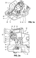
Figure 1 a is an elevation view of a portion of a closure latch for a vehicle door in accordance with an embodiment of the present invention, showing a lock lever in a first position; -
Figure 1b is a plan view of another portion of the vehicle latch shown inFigure 1a with some components shown as transparent for greater clarity; -
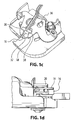
Figure 1c is a magnified perspective view of a portion of the closure latch shown inFigure 1b ; -
Figure 1d is an elevation view of the portion of the closure latch shown inFigure 1 c; -
Figure 1e is another magnified perspective view of the portion of the closure latch shown inFigure 1b with some components shown as transparent for greater clarity; -
Figure 2a is an elevation view of the closure latch shown inFigure 1a , showing the lock lever in a second position; -
Figure 2b is a plan view of the closure latch shown inFigure 2a ; -
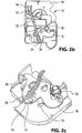
Figure 2c is a magnified perspective view of a portion of the closure latch shown inFigure 2b ; -
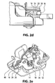
Figure 2d is an elevation view of the portion of the closure latch shown inFigure 2c ; -
Figure 2e is another magnified perspective view of the portion of the closure latch shown inFigure 2b with some components shown as transparent for greater clarity; and -
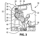
Figure 3 is an elevation view of the closure latch shown inFigure 1a , showing the lock lever in a third position. - Reference is made to
Figures 1 a and 1 b, which show portions of aclosure latch 10 for a door (not shown) of a vehicle (not shown), in accordance with an embodiment of the present invention. - The
closure latch 10 includes a ratchet 12 (Figure 1 b) , a pawl 14 (Figure 1b ), a first door release lever 16 (Figure 1c ), a second door release lever 18 (Figure 1 b) , a lock link 20 (Figure 1 b) , a lock lever 22 (Figure 1 a) , a lock lever actuator 24 (Figure 1 a) and a lock knob assembly 25 (a small portion of which is shown inFigure 1 a) . - Referring to
Figure 1b , theratchet 12 is movable between a closed position (Figure 1 b) wherein theratchet 12 retains a striker (not shown) mounted on the body (not shown) of the vehicle and an open position wherein theratchet 12 is unengaged with the striker. Aratchet biasing member 26 such as a suitable spring may be provided to bias theratchet 12 towards the open position. - The
pawl 14 is movable between a ratchet locking position (Figure 1 b) wherein thepawl 14 holds theratchet 12 in the closed position, and a release position wherein thepawl 14 permits theratchet 12 to move to its open position. A pawl biasing member 28 such as a suitable spring may be provided to bias thepawl 14 towards the ratchet locking position. - The first
door release lever 16 is operatively connected to theratchet 12 for movement from the closed position to the open position. The firstdoor release lever 16 may be operatively connected to theratchet 12 in any suitable way, such as by direct mechanical engagement (SeeFigure 1 e) . The firstdoor release lever 16 may be movable from a rest position to a door release position (not shown) wherein it moves thepawl 14 to the release position (not shown) so that theratchet 12 can be moved from the closed position to the open position under the urging of theratchet biasing member 26. - A first door release lever biasing member 30, such as a suitable spring, may be provided to bias the first door release lever 16 towards its rest position. Instead of having a first door release lever biasing member 30 that is dedicated solely to moving the first
door release lever 16 to its rest position, it is possible for thepawl 14 to move the firstdoor release lever 16 to its rest position, during movement of thepawl 14 to its ratchet locking position under the urging of the pawl biasing member 28. Thus, the pawl biasing member 28 may act as a first door release lever biasing member 30 as shown inFigure 1b . - The first door release lever 16 (
Figure 1c ) has a first locklink engagement surface 32 which is configured to be engaged by thelock link 20. - The second door release lever 18 (
Figure 2c ) is operatively connectable to the firstdoor release lever 16. The seconddoor release lever 18 may be operatively connectable to the firstdoor release lever 16 in any suitable way, such as through thelock link 20. The seconddoor release lever 18 includes a second locklink engagement surface 34 that is positioned to engage thelock link 20. The seconddoor release lever 18 may be movable from a rest position (Figure 1 c) to a door release position (not shown), which is described further below. - A second door release
lever biasing member 36, such as a suitable spring, may be provided to bias the second door release lever 18 towards its rest position. - The second
door release lever 18 may be moved from its rest position to its door release position by one or more means, such as by movement of an outer door handle (not shown) on the outside of the vehicle door (not shown). - The
lock link 20 may be movable between a first lock link position 20 (Figures 1a-1e ) wherein thelock link 20 is disengaged from the first door release lever, and a second lock link position (Figures 2a-2e ) wherein the seconddoor release lever 18 is operatively connected to the firstdoor release lever 16 through thelock link 20. More specifically, when a person pulls the outside door handle the seconddoor release lever 18 is moved from its rest position to its door release position and moves afirst end 38 of thelock link 20 with it. If thelock link 20 is in the first position (Figures 1a-1e ) and the person pulling the vehicle door handle is not in possession of an electronic vehicle key, then thefirst end 38 of thelock link 20 will sweep past the first locklink engagement surface 32 during movement of the second door release lever 18 to its door release position. As a result, the firstdoor release lever 16 will not be moved to its door release position and theratchet 12 will remain in its closed position. - When the
lock link 20 is in the second position (Figures 2a-2e ) and the seconddoor release lever 18 is moved from its rest position to its door release position, thefirst end 38 of thelock link 20 is positioned to engage the first locklink engagement surface 32 and will move the firstdoor release lever 16 to its door release position (not shown) thereby moving thepawl 14 andratchet 12 to open the vehicle door. - The
lock link 20 may be biased towards the second lock link position (Figure 2b ), by any suitable means, such as by asuitable spring 41. - The second end of the
lock link 20 is shown at 40 inFigure 1 a. At thesecond end 40, thelock link 20 has aguide pin 42 and a locklever engagement member 44. Theguide pin 42 engages aguide channel 46 that is fixedly connected to alatch housing member 48. Theguide channel 46 and theguide pin 42 together guide the movement of thelock link 20 between its first and second positions. - The
guide pin 42 is rotatable within the guide channel 46 (Figure 1b ). This permits thelock link 20 to pivot as necessary during movement of the second door release lever 18 between its rest position and its door release position. - The lock
lever engagement member 44 is engageable by the lock lever 22 (Figure 1 a) . Thelock lever 22 is movable between a first position (Figure 1 a) , a second position (Figure 2a ) and a third position (Figure 3 ). In the first position, thelock lever 22 holds thelock link 20 in the first lock link position (Figures 1a-1e ). Additionally, when thelock lever 22 is in the first position, thelock knob assembly 25 is in a locked lock knob assembly position. When thelock lever 22 is in the second position (Figure 2a ), it permits thelock link 20 to move to the second lock link position (Figure 2b ) under the urging of the lock link biasing member 41 (Figure 2b ), thereby providing an operative connection from the second door release lever 18 to the firstdoor release lever 16. Additionally, when thelock lever 22 is in the second position, thelock knob assembly 25 may be moved from the locked lock knob assembly position to an intermediate position (Figure 2a ) on the way to an unlocked lock knob assembly position (Figure 3 ). - As the
lock lever 22 moves away from the second position towards the third position, it may disengage from thelock link 20. The movement of thelock lever 22 to the third position causes thelock knob assembly 25 to move to the unlocked lock knob assembly position. - Rotation of the
lock lever 22 from the first position towards the third position is in an unlocking direction. Rotation of thelock lever 22 from the third position towards the first position is in a locking direction. - The
lock lever actuator 24 moves thelock lever 22 along the lock lever path between the first and third positions. Referring toFigure 1a , thelock lever actuator 24 includes amotor 50 and alinkage 52 that operative connects themotor 50 to thelock lever 22. Thelinkage 52 may include aworm gear 54 driven directly by themotor 50, afirst spur gear 56 driven by theworm gear 54, asecond spur gear 57 driven by thefirst spur gear 56 and alobed member 58 with at least onelobe 60 integrally connected to thesecond spur gear 57. Alobe receiving member 62 may be included as part of thelock lever 22 for receiving thelobe 60 and being driven thereby. - The movement of the
lock knob assembly 25 between its locked and unlocked positions may require significantly more torque than the movement of thelock link 20 between its first and second positions. As a result, there is a relationship between the strength (and therefore cost) of themotor 50, the effective torque increase that takes place in thelinkage 54 and the time required to carry out the movement of thelock knob assembly 25 between its locked and unlocked positions. - When the vehicle is locked and a person who is in possession of a proximity-actuated key (not shown) lifts the outside door handle of the vehicle, the initial movement of the outside door handle instructs the vehicle's on-board electronics to actuate the
motor 50. Themotor 50 causes the rotation of thelock lever 22 from the first lock lever position (Figure 1a ) through the second lock lever position (Figure 2a ) to the third lock lever position (Figure 3 ). The movement of thelock lever 22 from the first lock lever position to the second lock lever position causes thelock link 20 to move from the first lock link position to the second lock link position thereby operatively connecting the seconddoor release lever 18 to the firstdoor release lever 16. This process of actuating themotor 50 until the seconddoor release lever 18 is operatively connected to the firstdoor release lever 16 preferably takes place within a selected period of time, which may be, for example, less than 50 milliseconds. - Because the
lock link 20 is disengageable from the lock lever 22 (eg. during movement of thelock lever 22 between the second and third lock lever positions) the movement of thelock link 20 and the movement of thelock knob assembly 25 are independent of one another. By having the movements of thelock link 20 and thelock knob assembly 25 be independent from one another, the movement of thelock link 20 to its second position can be effected quickly so as to reduce the time to unlock the vehicle door, while the movement of thelock knob assembly 25 can remain longer so as to not require an undesirably strong (and therefore relatively expensive)motor 50. Preferably, the time required to unlock the vehicle door can be short enough so as to permit a person to open the door in one continuous motion without having to pause midway to permit the door to unlock. - To lock the vehicle door, the
motor 50 is rotated so that thelock lever 22 moves from the third lock lever position through the second lock lever position to the first lock lever position. Movement of thelock lever 22 from the third lock lever position to the second lock lever position moves thelock knob assembly 25 partway from the unlocked lock knob assembly position towards the locked lock knob assembly position. When thelock lever 22 is in the second lock lever position it has reengaged with thelock link 20. It will be understood that the point at which thelock link 20 is engaged by thelock lever 22 does not necessarily have to correspond to the point at which thelock link 20 operatively connects the seconddoor release lever 18 to the firstdoor release lever 16. In other words, the point at which thelock link 20 is engaged by thelock lever 22 may be somewhere suitable between the second and third lock lever positions. - Movement of the
lock lever 22 from the second lock lever position to the first lock lever position moves the lock link 20 from the second lock link position to the first lock link position, thereby operatively disconnecting the seconddoor release lever 18 from the firstdoor release lever 16. - It has been shown for the
lock lever 22 to control the operative connection between the second and first door release levers 18 and 16 via thelock link 20. - While the above description constitutes a plurality of embodiments of the present invention, it will be appreciated that the present invention is susceptible to further modification and change without departing from the claims.
Claims (9)
- A closure latch (10) for a vehicle door, comprising:a ratchet (12) movable between an open position and a closed position;a first door release lever (16) operatively connected to the ratchet (12);a second door release lever (18) operatively connectable to the first door release lever (16) through,a lock link (20) that is movable by a lock lever (22) movable along a lock lever path including a first lock lever position, wherein the second door release lever (18) is operatively disconnected from the first door release lever (16), a second lock lever position, wherein the lock lever (22) operatively connects the second door release lever (18) to the first door release lever (16), and a third lock lever position, wherein the lock lever (22) carries out an additional function, characterised in that at a selected point along a portion of the lock lever path between the second lock lever position and the third lock lever position, the lock lever (22) disengages from the lock link (20) so as to reduce the time to unlock the vehicle door.
- A closure latch (10) as claimed in claim 1, wherein the additional function is movement of a lock knob assembly (25) to an unlocked lock knob assembly position.
- A closure latch (10) as claimed in claim 2, wherein movement of the lock lever (22) to the first lock lever position causes movement of the lock knob assembly (25) to a locked lock knob assembly position.
- A closure latch (10) as claimed in claim 1, wherein the lock link (20) is movable by the lock lever (22) between a first lock link position wherein the lock link (20) is disengaged from the first door release lever (16), and a second lock link position wherein the second door release lever (18) is operatively connected to the first door release lever (16) through the lock link (20).
- A closure latch (10) as claimed in claim 4, wherein the lock link (20) is biased towards the second lock link position.
- A closure latch (10) as claimed in claim 1, further comprising a motorized lock lever actuator (24) that is operatively connected to the lock lever (22), wherein the motor (50) of the motorized lock lever actuator (24) is configured to be strong enough to move the lock lever (22) from the first position to the second position in less than 50 milliseconds.
- A closure latch (10) as claimed in claim 6, wherein the motorized lock lever actuator (24) is controllable to move the lock lever (22) from the first lock lever position to the third lock lever position through the second lock lever position in response to partial actuation of an outside door handle on the vehicle door.
- A closure latch (10) as claimed in claim 1, further comprising a pawl (14) movable between a ratchet locking position wherein the pawl (14) holds the ratchet (12) in the closed position, and a ratchet release position wherein the pawl (14) permits movement of the ratchet (12) to the open position.
- A closure latch (10) as claimed in claim 8, wherein the pawl (14) is biased towards the ratchet locking position.
Applications Claiming Priority (3)
| Application Number | Priority Date | Filing Date | Title |
|---|---|---|---|
| US97880007P | 2007-10-10 | 2007-10-10 | |
| US7537908P | 2008-06-25 | 2008-06-25 | |
| PCT/CA2008/001807 WO2009046539A1 (en) | 2007-10-10 | 2008-10-10 | Door latch with fast unlock |
Publications (3)
| Publication Number | Publication Date |
|---|---|
| EP2195500A1 EP2195500A1 (en) | 2010-06-16 |
| EP2195500A4 EP2195500A4 (en) | 2014-07-02 |
| EP2195500B1 true EP2195500B1 (en) | 2017-05-03 |
Family
ID=40548914
Family Applications (1)
| Application Number | Title | Priority Date | Filing Date |
|---|---|---|---|
| EP08837202.4A Not-in-force EP2195500B1 (en) | 2007-10-10 | 2008-10-10 | Door latch with fast unlock |
Country Status (3)
| Country | Link |
|---|---|
| US (1) | US9416566B2 (en) |
| EP (1) | EP2195500B1 (en) |
| WO (1) | WO2009046539A1 (en) |
Families Citing this family (6)
| Publication number | Priority date | Publication date | Assignee | Title |
|---|---|---|---|---|
| EP2195500B1 (en) * | 2007-10-10 | 2017-05-03 | Magna Closures Inc. | Door latch with fast unlock |
| GB2480490B (en) * | 2010-05-21 | 2016-06-08 | Inteva Products Usa Llc | Latch assembly |
| DE102015106124A1 (en) | 2014-04-25 | 2015-10-29 | Magna Closures Inc. | Door lock with quick release |
| US10392838B2 (en) | 2015-06-11 | 2019-08-27 | Magna Closures Inc. | Key cylinder release mechanism for vehicle closure latches, latch assembly therewith and method of mechanically releasing a vehicle closure latch |
| DE102016215476A1 (en) | 2015-09-11 | 2017-03-16 | Magna Closures S.P.A. | ELECTRIC DOOR LOCK |
| US10895095B2 (en) * | 2016-10-06 | 2021-01-19 | Magna Closures S.P.A. | Power closure latch assembly with cinch mechanism having ratchet retention function |
Family Cites Families (45)
| Publication number | Priority date | Publication date | Assignee | Title |
|---|---|---|---|---|
| US538855A (en) * | 1895-05-07 | Leonidas g | ||
| US3602019A (en) * | 1969-07-01 | 1971-08-31 | Aisin Seiki | Door-locking arrangement for automotive vehicle |
| US3583742A (en) * | 1969-08-26 | 1971-06-08 | Gen Motors Corp | Door latch mechanism |
| FR2063719A5 (en) * | 1969-10-28 | 1971-07-09 | Peugeot & Renault | |
| US3695662A (en) * | 1970-09-18 | 1972-10-03 | Atwood Vacuum Machine Co | Latch for vehicle doors |
| US4269440A (en) * | 1975-11-08 | 1981-05-26 | Fichtel & Sachs Ag | Electrically energized operating mechanism for the door of a vehicle and the like, and drive arrangement for the mechanism |
| JPS5430317Y2 (en) * | 1976-04-07 | 1979-09-25 | ||
| DE2721970A1 (en) * | 1977-05-14 | 1978-11-16 | Fichtel & Sachs Ag | LOCKING AND / OR LOCKING DEVICE FOR VEHICLE DOORS |
| JPS57172083A (en) * | 1981-04-15 | 1982-10-22 | Nissan Motor | Door lock manipulating apparatus |
| JPS5811275A (en) * | 1981-07-08 | 1983-01-22 | 日産自動車株式会社 | Apparatus for unlocking door lock of automobile in emergency |
| US4575138A (en) * | 1982-09-22 | 1986-03-11 | Ohi Seisakusho Co., Ltd. | Door latching device |
| JPH0747904B2 (en) * | 1986-04-14 | 1995-05-24 | 富士重工業株式会社 | Automotive door control device |
| KR930000850B1 (en) * | 1986-12-26 | 1993-02-06 | 가부시끼가이샤 안세이고오교오 | Automotive Door Lock Device |
| JPH0452363Y2 (en) * | 1988-05-18 | 1992-12-09 | ||
| DE3823502A1 (en) * | 1988-07-12 | 1990-01-18 | Kiekert Gmbh Co Kg | MOTOR VEHICLE LOCKING DEVICE |
| JP2658272B2 (en) * | 1988-09-30 | 1997-09-30 | アイシン精機株式会社 | Door closing device |
| JP2514430B2 (en) * | 1989-06-22 | 1996-07-10 | 三井金属鉱業株式会社 | Switch device in vehicle locking device |
| JP2532993B2 (en) * | 1990-10-23 | 1996-09-11 | 三井金属鉱業株式会社 | Vehicle door lock device |
| JP2573536B2 (en) * | 1992-07-02 | 1997-01-22 | 三井金属鉱業株式会社 | Vehicle door lock device with super lock mechanism |
| JP3324223B2 (en) * | 1993-06-04 | 2002-09-17 | アイシン精機株式会社 | Door lock device |
| JP3098943B2 (en) * | 1995-10-09 | 2000-10-16 | 三井金属鉱業株式会社 | Vehicle child lock device |
| FR2750155B1 (en) * | 1996-06-25 | 1998-09-04 | Valeo Securite Habitacle | DEVICE FOR CONTROLLING THE OPENING OF A LOCK OF A MOTOR VEHICLE OPENING ELEMENT |
| US6386599B1 (en) * | 1999-08-12 | 2002-05-14 | John Phillip Chevalier | Latch arrangement for automotive door |
| FR2778196B1 (en) * | 1998-04-30 | 2000-06-23 | Valeo Securite Habitacle | MOTOR VEHICLE DOOR LOCK |
| CA2299921A1 (en) * | 1999-03-05 | 2000-09-05 | Strattec Security Corporation | Modular latch apparatus and method |
| JP3301738B2 (en) * | 1999-04-21 | 2002-07-15 | 三井金属鉱業株式会社 | Vehicle door latch device with double action mechanism |
| US6328353B1 (en) * | 1999-06-16 | 2001-12-11 | Atoma International | Vehicle door latch assembly |
| AU7922400A (en) | 1999-10-29 | 2001-05-14 | Kiekert Aktiengesellschaft | Locking system for the door of a motor vehicle |
| US6880866B2 (en) | 2000-02-25 | 2005-04-19 | Intier Automotive Closures Inc. | Vehicle door latch |
| DE10023311B4 (en) | 2000-05-15 | 2006-02-16 | Brose Schließsysteme GmbH & Co.KG | Motor vehicle door locking system with quick release |
| JP3921043B2 (en) * | 2000-10-30 | 2007-05-30 | 株式会社大井製作所 | Vehicle door lock device |
| DE10149478B4 (en) | 2001-10-08 | 2007-02-15 | Siemens Ag | Door locking device |
| JP4150655B2 (en) * | 2003-11-06 | 2008-09-17 | 三井金属鉱業株式会社 | Door opener |
| US7264283B2 (en) * | 2003-12-10 | 2007-09-04 | Intier Automotive Closures Inc. | Vehicle latch with partially decoupled key cylinder lever |
| JP4015638B2 (en) * | 2004-05-10 | 2007-11-28 | 株式会社ホンダロック | Vehicle door opening and closing device |
| GB2416186B (en) | 2004-07-12 | 2007-04-04 | Lear Corp | Mechanical handle switch assembly |
| FR2877977B1 (en) * | 2004-11-12 | 2007-01-19 | Arvinmeritor Light Vehicle Sys | LOCK OF MOTOR VEHICLE |
| JP4535856B2 (en) * | 2004-11-26 | 2010-09-01 | 三井金属鉱業株式会社 | Door opener |
| WO2006099730A1 (en) * | 2005-03-23 | 2006-09-28 | Magna Closures Inc. | Global side door latch |
| US7464627B2 (en) * | 2005-10-27 | 2008-12-16 | Stoneridge Control Devices, Inc. | Passive entry actuator |
| US7270029B1 (en) * | 2006-07-27 | 2007-09-18 | Ford Global Technologies, Llc | Passive entry side door latch release system |
| US7399010B2 (en) | 2006-09-21 | 2008-07-15 | Keykert Usa, Usa | Power-actuated motor-vehicle door latch with quick unlock |
| EP2195500B1 (en) * | 2007-10-10 | 2017-05-03 | Magna Closures Inc. | Door latch with fast unlock |
| JP4473918B2 (en) * | 2008-03-28 | 2010-06-02 | 三井金属鉱業株式会社 | Door latch device for automobile |
| JP4760887B2 (en) * | 2008-09-29 | 2011-08-31 | アイシン精機株式会社 | Door lock device |
-
2008
- 2008-10-10 EP EP08837202.4A patent/EP2195500B1/en not_active Not-in-force
- 2008-10-10 US US12/682,096 patent/US9416566B2/en not_active Expired - Fee Related
- 2008-10-10 WO PCT/CA2008/001807 patent/WO2009046539A1/en not_active Ceased
Non-Patent Citations (1)
| Title |
|---|
| None * |
Also Published As
| Publication number | Publication date |
|---|---|
| WO2009046539A1 (en) | 2009-04-16 |
| EP2195500A4 (en) | 2014-07-02 |
| EP2195500A1 (en) | 2010-06-16 |
| US9416566B2 (en) | 2016-08-16 |
| US20100207400A1 (en) | 2010-08-19 |
Similar Documents
| Publication | Publication Date | Title |
|---|---|---|
| US10683682B2 (en) | Closure latch for vehicle door having double pull release mechanism driven by child lock actuator | |
| US10907385B2 (en) | Universal global latch system | |
| US8562033B2 (en) | Double lock override mechanism for vehicular passive entry door latch | |
| US8474888B2 (en) | Closure latch for vehicle door | |
| CN108999500B (en) | Closure latch assembly with latch mechanism and outside release mechanism with reset device | |
| US4342209A (en) | Central vehicle door-lock system | |
| US8522583B2 (en) | Door latch with emergency lock actuator and ‘impatient passenger’ feature | |
| US11885158B2 (en) | Deployable handle system using remote actuator | |
| EP1084918B1 (en) | Latch | |
| US20150284977A1 (en) | Motor vehicle door lock | |
| US5844470A (en) | Device for controlling opening of a motor vehicle door | |
| CN118369485A (en) | Combination motor vehicle lock | |
| KR20080038343A (en) | Motor vehicle and door lock for a door of a motor vehicle | |
| JP2000500835A (en) | Vehicle door lock actuator | |
| US11499348B2 (en) | Power child lock device | |
| US9416566B2 (en) | Door latch with fast unlock | |
| US20250154803A1 (en) | Operating Mechanism for Vehicle Doors | |
| US20180195315A1 (en) | Freewheeling inertia mechanism for closure latch assembly | |
| US6494505B2 (en) | Automotive door lock assembly | |
| EP1580365A1 (en) | Latch mechanism | |
| CN121358925A (en) | Motor vehicle locks | |
| US20240263493A1 (en) | Securing Arrangement for a Flap or Cover of a Vehicle | |
| EP1290301B1 (en) | Latch apparatus and method | |
| WO2011002770A1 (en) | Vehicle door-latch manual release |
Legal Events
| Date | Code | Title | Description |
|---|---|---|---|
| PUAI | Public reference made under article 153(3) epc to a published international application that has entered the european phase |
Free format text: ORIGINAL CODE: 0009012 |
|
| 17P | Request for examination filed |
Effective date: 20100329 |
|
| AK | Designated contracting states |
Kind code of ref document: A1 Designated state(s): AT BE BG CH CY CZ DE DK EE ES FI FR GB GR HR HU IE IS IT LI LT LU LV MC MT NL NO PL PT RO SE SI SK TR |
|
| AX | Request for extension of the european patent |
Extension state: AL BA MK RS |
|
| DAX | Request for extension of the european patent (deleted) | ||
| REG | Reference to a national code |
Ref country code: DE Ref legal event code: R079 Ref document number: 602008050115 Country of ref document: DE Free format text: PREVIOUS MAIN CLASS: E05B0065320000 Ipc: E05C0003160000 |
|
| A4 | Supplementary search report drawn up and despatched |
Effective date: 20140602 |
|
| RIC1 | Information provided on ipc code assigned before grant |
Ipc: E05C 3/16 20060101AFI20140526BHEP Ipc: E05B 85/00 20140101ALI20140526BHEP Ipc: E05B 81/06 20140101ALI20140526BHEP |
|
| 17Q | First examination report despatched |
Effective date: 20150611 |
|
| GRAP | Despatch of communication of intention to grant a patent |
Free format text: ORIGINAL CODE: EPIDOSNIGR1 |
|
| INTG | Intention to grant announced |
Effective date: 20161020 |
|
| GRAS | Grant fee paid |
Free format text: ORIGINAL CODE: EPIDOSNIGR3 |
|
| STAA | Information on the status of an ep patent application or granted ep patent |
Free format text: STATUS: GRANT OF PATENT IS INTENDED |
|
| GRAJ | Information related to disapproval of communication of intention to grant by the applicant or resumption of examination proceedings by the epo deleted |
Free format text: ORIGINAL CODE: EPIDOSDIGR1 |
|
| GRAL | Information related to payment of fee for publishing/printing deleted |
Free format text: ORIGINAL CODE: EPIDOSDIGR3 |
|
| STAA | Information on the status of an ep patent application or granted ep patent |
Free format text: STATUS: EXAMINATION IS IN PROGRESS |
|
| GRAP | Despatch of communication of intention to grant a patent |
Free format text: ORIGINAL CODE: EPIDOSNIGR1 |
|
| STAA | Information on the status of an ep patent application or granted ep patent |
Free format text: STATUS: GRANT OF PATENT IS INTENDED |
|
| GRAA | (expected) grant |
Free format text: ORIGINAL CODE: 0009210 |
|
| STAA | Information on the status of an ep patent application or granted ep patent |
Free format text: STATUS: THE PATENT HAS BEEN GRANTED |
|
| INTC | Intention to grant announced (deleted) | ||
| INTG | Intention to grant announced |
Effective date: 20170313 |
|
| AK | Designated contracting states |
Kind code of ref document: B1 Designated state(s): AT BE BG CH CY CZ DE DK EE ES FI FR GB GR HR HU IE IS IT LI LT LU LV MC MT NL NO PL PT RO SE SI SK TR |
|
| REG | Reference to a national code |
Ref country code: GB Ref legal event code: FG4D |
|
| REG | Reference to a national code |
Ref country code: AT Ref legal event code: REF Ref document number: 890181 Country of ref document: AT Kind code of ref document: T Effective date: 20170515 Ref country code: CH Ref legal event code: EP |
|
| REG | Reference to a national code |
Ref country code: IE Ref legal event code: FG4D |
|
| REG | Reference to a national code |
Ref country code: DE Ref legal event code: R096 Ref document number: 602008050115 Country of ref document: DE |
|
| REG | Reference to a national code |
Ref country code: NL Ref legal event code: MP Effective date: 20170503 |
|
| REG | Reference to a national code |
Ref country code: AT Ref legal event code: MK05 Ref document number: 890181 Country of ref document: AT Kind code of ref document: T Effective date: 20170503 |
|
| REG | Reference to a national code |
Ref country code: LT Ref legal event code: MG4D |
|
| PG25 | Lapsed in a contracting state [announced via postgrant information from national office to epo] |
Ref country code: HR Free format text: LAPSE BECAUSE OF FAILURE TO SUBMIT A TRANSLATION OF THE DESCRIPTION OR TO PAY THE FEE WITHIN THE PRESCRIBED TIME-LIMIT Effective date: 20170503 Ref country code: NO Free format text: LAPSE BECAUSE OF FAILURE TO SUBMIT A TRANSLATION OF THE DESCRIPTION OR TO PAY THE FEE WITHIN THE PRESCRIBED TIME-LIMIT Effective date: 20170803 Ref country code: LT Free format text: LAPSE BECAUSE OF FAILURE TO SUBMIT A TRANSLATION OF THE DESCRIPTION OR TO PAY THE FEE WITHIN THE PRESCRIBED TIME-LIMIT Effective date: 20170503 Ref country code: AT Free format text: LAPSE BECAUSE OF FAILURE TO SUBMIT A TRANSLATION OF THE DESCRIPTION OR TO PAY THE FEE WITHIN THE PRESCRIBED TIME-LIMIT Effective date: 20170503 Ref country code: GR Free format text: LAPSE BECAUSE OF FAILURE TO SUBMIT A TRANSLATION OF THE DESCRIPTION OR TO PAY THE FEE WITHIN THE PRESCRIBED TIME-LIMIT Effective date: 20170804 Ref country code: FI Free format text: LAPSE BECAUSE OF FAILURE TO SUBMIT A TRANSLATION OF THE DESCRIPTION OR TO PAY THE FEE WITHIN THE PRESCRIBED TIME-LIMIT Effective date: 20170503 Ref country code: ES Free format text: LAPSE BECAUSE OF FAILURE TO SUBMIT A TRANSLATION OF THE DESCRIPTION OR TO PAY THE FEE WITHIN THE PRESCRIBED TIME-LIMIT Effective date: 20170503 |
|
| PG25 | Lapsed in a contracting state [announced via postgrant information from national office to epo] |
Ref country code: LV Free format text: LAPSE BECAUSE OF FAILURE TO SUBMIT A TRANSLATION OF THE DESCRIPTION OR TO PAY THE FEE WITHIN THE PRESCRIBED TIME-LIMIT Effective date: 20170503 Ref country code: NL Free format text: LAPSE BECAUSE OF FAILURE TO SUBMIT A TRANSLATION OF THE DESCRIPTION OR TO PAY THE FEE WITHIN THE PRESCRIBED TIME-LIMIT Effective date: 20170503 Ref country code: PL Free format text: LAPSE BECAUSE OF FAILURE TO SUBMIT A TRANSLATION OF THE DESCRIPTION OR TO PAY THE FEE WITHIN THE PRESCRIBED TIME-LIMIT Effective date: 20170503 Ref country code: SE Free format text: LAPSE BECAUSE OF FAILURE TO SUBMIT A TRANSLATION OF THE DESCRIPTION OR TO PAY THE FEE WITHIN THE PRESCRIBED TIME-LIMIT Effective date: 20170503 Ref country code: IS Free format text: LAPSE BECAUSE OF FAILURE TO SUBMIT A TRANSLATION OF THE DESCRIPTION OR TO PAY THE FEE WITHIN THE PRESCRIBED TIME-LIMIT Effective date: 20170903 Ref country code: BG Free format text: LAPSE BECAUSE OF FAILURE TO SUBMIT A TRANSLATION OF THE DESCRIPTION OR TO PAY THE FEE WITHIN THE PRESCRIBED TIME-LIMIT Effective date: 20170803 |
|
| PG25 | Lapsed in a contracting state [announced via postgrant information from national office to epo] |
Ref country code: DK Free format text: LAPSE BECAUSE OF FAILURE TO SUBMIT A TRANSLATION OF THE DESCRIPTION OR TO PAY THE FEE WITHIN THE PRESCRIBED TIME-LIMIT Effective date: 20170503 Ref country code: SK Free format text: LAPSE BECAUSE OF FAILURE TO SUBMIT A TRANSLATION OF THE DESCRIPTION OR TO PAY THE FEE WITHIN THE PRESCRIBED TIME-LIMIT Effective date: 20170503 Ref country code: CZ Free format text: LAPSE BECAUSE OF FAILURE TO SUBMIT A TRANSLATION OF THE DESCRIPTION OR TO PAY THE FEE WITHIN THE PRESCRIBED TIME-LIMIT Effective date: 20170503 Ref country code: RO Free format text: LAPSE BECAUSE OF FAILURE TO SUBMIT A TRANSLATION OF THE DESCRIPTION OR TO PAY THE FEE WITHIN THE PRESCRIBED TIME-LIMIT Effective date: 20170503 Ref country code: EE Free format text: LAPSE BECAUSE OF FAILURE TO SUBMIT A TRANSLATION OF THE DESCRIPTION OR TO PAY THE FEE WITHIN THE PRESCRIBED TIME-LIMIT Effective date: 20170503 |
|
| REG | Reference to a national code |
Ref country code: DE Ref legal event code: R097 Ref document number: 602008050115 Country of ref document: DE |
|
| PG25 | Lapsed in a contracting state [announced via postgrant information from national office to epo] |
Ref country code: IT Free format text: LAPSE BECAUSE OF FAILURE TO SUBMIT A TRANSLATION OF THE DESCRIPTION OR TO PAY THE FEE WITHIN THE PRESCRIBED TIME-LIMIT Effective date: 20170503 |
|
| PLBE | No opposition filed within time limit |
Free format text: ORIGINAL CODE: 0009261 |
|
| STAA | Information on the status of an ep patent application or granted ep patent |
Free format text: STATUS: NO OPPOSITION FILED WITHIN TIME LIMIT |
|
| 26N | No opposition filed |
Effective date: 20180206 |
|
| PG25 | Lapsed in a contracting state [announced via postgrant information from national office to epo] |
Ref country code: SI Free format text: LAPSE BECAUSE OF FAILURE TO SUBMIT A TRANSLATION OF THE DESCRIPTION OR TO PAY THE FEE WITHIN THE PRESCRIBED TIME-LIMIT Effective date: 20170503 Ref country code: MC Free format text: LAPSE BECAUSE OF FAILURE TO SUBMIT A TRANSLATION OF THE DESCRIPTION OR TO PAY THE FEE WITHIN THE PRESCRIBED TIME-LIMIT Effective date: 20170503 |
|
| REG | Reference to a national code |
Ref country code: CH Ref legal event code: PL |
|
| GBPC | Gb: european patent ceased through non-payment of renewal fee |
Effective date: 20171010 |
|
| REG | Reference to a national code |
Ref country code: IE Ref legal event code: MM4A |
|
| REG | Reference to a national code |
Ref country code: FR Ref legal event code: ST Effective date: 20180629 |
|
| PG25 | Lapsed in a contracting state [announced via postgrant information from national office to epo] |
Ref country code: GB Free format text: LAPSE BECAUSE OF NON-PAYMENT OF DUE FEES Effective date: 20171010 Ref country code: LU Free format text: LAPSE BECAUSE OF NON-PAYMENT OF DUE FEES Effective date: 20171010 Ref country code: CH Free format text: LAPSE BECAUSE OF NON-PAYMENT OF DUE FEES Effective date: 20171031 Ref country code: LI Free format text: LAPSE BECAUSE OF NON-PAYMENT OF DUE FEES Effective date: 20171031 |
|
| REG | Reference to a national code |
Ref country code: BE Ref legal event code: MM Effective date: 20171031 |
|
| PG25 | Lapsed in a contracting state [announced via postgrant information from national office to epo] |
Ref country code: FR Free format text: LAPSE BECAUSE OF NON-PAYMENT OF DUE FEES Effective date: 20171031 Ref country code: BE Free format text: LAPSE BECAUSE OF NON-PAYMENT OF DUE FEES Effective date: 20171031 |
|
| PG25 | Lapsed in a contracting state [announced via postgrant information from national office to epo] |
Ref country code: MT Free format text: LAPSE BECAUSE OF NON-PAYMENT OF DUE FEES Effective date: 20171010 |
|
| PG25 | Lapsed in a contracting state [announced via postgrant information from national office to epo] |
Ref country code: IE Free format text: LAPSE BECAUSE OF NON-PAYMENT OF DUE FEES Effective date: 20171010 |
|
| PGFP | Annual fee paid to national office [announced via postgrant information from national office to epo] |
Ref country code: DE Payment date: 20180925 Year of fee payment: 11 |
|
| PG25 | Lapsed in a contracting state [announced via postgrant information from national office to epo] |
Ref country code: HU Free format text: LAPSE BECAUSE OF FAILURE TO SUBMIT A TRANSLATION OF THE DESCRIPTION OR TO PAY THE FEE WITHIN THE PRESCRIBED TIME-LIMIT; INVALID AB INITIO Effective date: 20081010 |
|
| PG25 | Lapsed in a contracting state [announced via postgrant information from national office to epo] |
Ref country code: CY Free format text: LAPSE BECAUSE OF NON-PAYMENT OF DUE FEES Effective date: 20170503 |
|
| PG25 | Lapsed in a contracting state [announced via postgrant information from national office to epo] |
Ref country code: TR Free format text: LAPSE BECAUSE OF FAILURE TO SUBMIT A TRANSLATION OF THE DESCRIPTION OR TO PAY THE FEE WITHIN THE PRESCRIBED TIME-LIMIT Effective date: 20170503 |
|
| REG | Reference to a national code |
Ref country code: DE Ref legal event code: R119 Ref document number: 602008050115 Country of ref document: DE |
|
| PG25 | Lapsed in a contracting state [announced via postgrant information from national office to epo] |
Ref country code: PT Free format text: LAPSE BECAUSE OF FAILURE TO SUBMIT A TRANSLATION OF THE DESCRIPTION OR TO PAY THE FEE WITHIN THE PRESCRIBED TIME-LIMIT Effective date: 20170503 |
|
| PG25 | Lapsed in a contracting state [announced via postgrant information from national office to epo] |
Ref country code: DE Free format text: LAPSE BECAUSE OF NON-PAYMENT OF DUE FEES Effective date: 20200501 |