EP2195237B1 - Load detection in an aircraft landing gear - Google Patents
Load detection in an aircraft landing gear Download PDFInfo
- Publication number
- EP2195237B1 EP2195237B1 EP08836934A EP08836934A EP2195237B1 EP 2195237 B1 EP2195237 B1 EP 2195237B1 EP 08836934 A EP08836934 A EP 08836934A EP 08836934 A EP08836934 A EP 08836934A EP 2195237 B1 EP2195237 B1 EP 2195237B1
- Authority
- EP
- European Patent Office
- Prior art keywords
- load
- landing gear
- arm
- pressure
- unit
- Prior art date
- Legal status (The legal status is an assumption and is not a legal conclusion. Google has not performed a legal analysis and makes no representation as to the accuracy of the status listed.)
- Active
Links
Images



Classifications
-
- B—PERFORMING OPERATIONS; TRANSPORTING
- B64—AIRCRAFT; AVIATION; COSMONAUTICS
- B64C—AEROPLANES; HELICOPTERS
- B64C25/00—Alighting gear
- B64C25/32—Alighting gear characterised by elements which contact the ground or similar surface
- B64C25/34—Alighting gear characterised by elements which contact the ground or similar surface wheeled type, e.g. multi-wheeled bogies
-
- B—PERFORMING OPERATIONS; TRANSPORTING
- B64—AIRCRAFT; AVIATION; COSMONAUTICS
- B64C—AEROPLANES; HELICOPTERS
- B64C25/00—Alighting gear
- B64C25/02—Undercarriages
-
- B—PERFORMING OPERATIONS; TRANSPORTING
- B64—AIRCRAFT; AVIATION; COSMONAUTICS
- B64C—AEROPLANES; HELICOPTERS
- B64C25/00—Alighting gear
- B64C25/32—Alighting gear characterised by elements which contact the ground or similar surface
- B64C25/58—Arrangements or adaptations of shock-absorbers or springs
-
- B—PERFORMING OPERATIONS; TRANSPORTING
- B64—AIRCRAFT; AVIATION; COSMONAUTICS
- B64D—EQUIPMENT FOR FITTING IN OR TO AIRCRAFT; FLIGHT SUITS; PARACHUTES; ARRANGEMENT OR MOUNTING OF POWER PLANTS OR PROPULSION TRANSMISSIONS IN AIRCRAFT
- B64D45/00—Aircraft indicators or protectors not otherwise provided for
-
- F—MECHANICAL ENGINEERING; LIGHTING; HEATING; WEAPONS; BLASTING
- F16—ENGINEERING ELEMENTS AND UNITS; GENERAL MEASURES FOR PRODUCING AND MAINTAINING EFFECTIVE FUNCTIONING OF MACHINES OR INSTALLATIONS; THERMAL INSULATION IN GENERAL
- F16F—SPRINGS; SHOCK-ABSORBERS; MEANS FOR DAMPING VIBRATION
- F16F9/00—Springs, vibration-dampers, shock-absorbers, or similarly-constructed movement-dampers using a fluid or the equivalent as damping medium
- F16F9/32—Details
- F16F9/3264—Arrangements for indicating, e.g. fluid level; Arrangements for checking dampers
-
- G—PHYSICS
- G01—MEASURING; TESTING
- G01L—MEASURING FORCE, STRESS, TORQUE, WORK, MECHANICAL POWER, MECHANICAL EFFICIENCY, OR FLUID PRESSURE
- G01L23/00—Devices or apparatus for measuring or indicating or recording rapid changes, such as oscillations, in the pressure of steam, gas, or liquid; Indicators for determining work or energy of steam, internal-combustion, or other fluid-pressure engines from the condition of the working fluid
-
- G—PHYSICS
- G01—MEASURING; TESTING
- G01P—MEASURING LINEAR OR ANGULAR SPEED, ACCELERATION, DECELERATION, OR SHOCK; INDICATING PRESENCE, ABSENCE, OR DIRECTION, OF MOVEMENT
- G01P15/00—Measuring acceleration; Measuring deceleration; Measuring shock, i.e. sudden change of acceleration
-
- B—PERFORMING OPERATIONS; TRANSPORTING
- B64—AIRCRAFT; AVIATION; COSMONAUTICS
- B64D—EQUIPMENT FOR FITTING IN OR TO AIRCRAFT; FLIGHT SUITS; PARACHUTES; ARRANGEMENT OR MOUNTING OF POWER PLANTS OR PROPULSION TRANSMISSIONS IN AIRCRAFT
- B64D45/00—Aircraft indicators or protectors not otherwise provided for
- B64D2045/008—Devices for detecting or indicating hard landing
Definitions
- the present invention relates to load detection in a landing gear for an aircraft.
- a landing gear for an aircraft comprises a shock absorber strut with upper and lower telescoping portions, the upper portion being connectable to the airframe of the aircraft; an arm to extend fore and aft relative to the aircraft and carrying a landing wheel, and pivotally connected by a main pivot to the lower portion of the shock absorber strut; and a load reacting unit connected between the arm and the shock absorber strut for reacting to load applied between the arm and shock absorber strut on landing, and an indicator for monitoring the load applied to the load reacting unit on landing.
- the invention relates to a method of monitoring the load on a landing gear as claimed in claim 19.
- the invention recognises that friction from sliding bearings in the shock absorber strut make a significant difference to the load for a given shock absorber internal pressure (or alternatively the shock absorber pressure may be different for the same applied load, depending upon bearing friction).
- Bearing friction is highly variable, depending upon the coefficient of friction and the load applied normal to the bearings.
- the invention recognises that more accurate measurement of load can be made by measuring the load in the load reacting unit, which is less affected by friction than the shock absorber strut. That is, in a fluid pressure load reacting unit the pressure is much more closely related to the load applied to the arm than is the pressure in the shock absorber strut.
- the load reacting unit may be pin-jointed, or mounted on spherical bearings at each end, resulting in minimal loading normal to its sliding bearings.
- the fluid may be air (or another gas), but more preferably is a liquid.
- the arm may be the arm of semi-levered landing gear, and/or a bogie beam with fore and aft landing wheels.
- EP1041001 discloses the preamble of independent claim 1. It shows a semi-levered landing gear including a main strut and pivotal bogie arrangement. An auxiliary strut including a lock-up valve is connected between the main strut and one end of the bogie, arranged to lock up at in intermediate length on take off. When the main strut extends, the locked auxiliary strut causes the landing gear to tilt into a nose-up configuration.
- the landing gear illustrated in Figure 1 comprises a main hydraulic shock absorber strut 1 comprising an upper portion 2 connectable to the underside of an aircraft at its upper end, and a lower portion 3 which telescopes within the upper portion 2 during take-off and landing.
- a bogie beam 4 extends fore and aft of the aircraft and is pivotally connected to the bottom of the lower portion 3 by a main pivot 5 in the mid-region of the bogie beam 4.
- Axles 6, 6' are mounted at each end of the bogie beam 4 and carry wheels 7, 7'.
- the internal construction of the main strut 1 is not shown in Figure 1 but it may take a conventional form such as shown in GB1510554 and contain pressurised oil and gas.
- a load reacting unit 9 is connected between the upper portion 2 of the main strut and the forward section of the bogie beam 4 to control the angular position of the bogie beam during taxiing, take-off and landing.
- the unit 9 comprises an outer cylinder casing 10 with a closed upper end carrying an upper connector 11 which is pivotally connected at 12 to the upper end 2 of the main strut.
- a piston rod 23 extends from the lower end of the cylinder casing 10 and carries a lower connector 13 which is pivotally connected at 14 to the front end of the bogie beam between the axle 6 and the main pivot 5.
- a side stay (not shown) is connected between the upper portion 2 of the shock absorber strut and the aircraft, and moves with the strut when the landing gear is moved to a stowed position in the aircraft by a stowing actuator (not shown).
- the load reacting unit 9 has a piston 15 within the cylinder casing 10 that divides the internal space into a high pressure chamber 16 on one side of the piston and a low pressure chamber 17 on the other side of the piston with an internal shoulder 18 between the two chambers 16, 17 against which the piston is urged by high pressure fluid within the chamber 16.
- the piston rod 23 extends through an axial aperture 19 in the piston and carries a retainer 20 at its inner end to hold the piston 15 captive on the rod 23. A tensile force applied between the connectors 11, 13 will cause the retainer to engage the piston 15 and for the two to move together in acting against the high pressure fluid, which flows in a hydraulic control circuit including a high pressure port 21 with a flow restrictor.
- movement of the piston 15 and piston rod 23 with the tensile load may be accommodated by valving in the piston to allow the flow of oil between the chambers 16, 17 either side of the piston, the flow being more restricted when the unit is extending, compared with the flow when the unit is retracting.
- the bogie beam 4 is tilted into the position shown in Figure 1 with the rear wheel 17' contacting the ground on landing.
- the bogie beam 4 then rotates anticlockwise, thereby compressing the strut 1.
- the high pressure in the load reacting unit 9 ensures that there is little or no extension of unit 9.
- the shortening of the strut 1 continues until the forward wheel 7 makes contact with the ground, thereby relieving the tensile load in the unit 9.
- the load reacting unit 9 then contracts to accommodate the shortening of the main strut 1.
- the main strut 1 then functions as a conventional shock absorber.
- a landing load indicator 60 is provided in the unit 9 to be responsive to the internal fluid pressure.
- the indicator 60 shown in Figure 2 comprises a bobbin 62 that is a slide fit in a bore 63 of a body 64 that is exposed at an inner end to the fluid pressure and opens to the exterior of the unit 9 for inspection by service engineers.
- the bobbin 62 is sealed in the bore 63 by an O-ring seal 65 seated in an annular groove 66 in the bobbin.
- a spring-loaded detent 67 is mounted in a lateral bore 68 in the body 64 so as to be urged towards the bore 63.
- the detent 67 has a rounded end formed by a ball 67' which engages a profiled surface of the bobbin 62.
- the profile consists of two annular grooves 69, 69' spaced apart by a barrel-shaped shoulder 70 over which the rounded end of the detent 67 rides as the bobbin moves from the normal retracted position of Figure 2 to an extended overload indicating position of Figure 4 .
- the barrel shape of the shoulder 70 ensures a controlled movement of the bobbin 62 with increasing pressure as shown in Figure 3 , and the force of the engagement of the detent 67 with the bobbin once it has passed the crown of the barrel-shaped shoulder 70 serves to assist operation to the extended position. Once the indicator has been operated, the force of engagement of the detent in the groove 69' is sufficient to hold the bobbin in place under increased internal fluid pressure.
- the bobbin 62 is preferably painted a bright colour to increase its visibility once operated.
- the bobbin 62 may be reset by manual depression or, if needed, a special tool or key may be provided.
- the invention makes use of the close correlation between the pressure in the load reaction unit 9 and the load on the aft axle 4, on touchdown.
- the bearing friction for the auxiliary actuator 9 will be small, because it is mounted on spherical bearings 12, 14 at each end. Friction at the bogie pivot 5 and seal friction will also exist, but can be shown to be small. Furthermore the bogie will always be rotating in the same direction during initial compression on landing. Therefore the results can be compensated to account for the mean friction value, with the only remaining error being due to a variation in friction.
- the appropriate pressure threshold value at which the indicator operates may be determined after taking into account the normal aircraft attitude and landing gear geometry, acceptable landing gear load limits, and an allowance for variations or tolerances.
- a single indicator 60 may be provided in the load reaction unit 9 to give an indication of the occurrence of an overload condition during landing.
- two or more indicators 60 may be provided, each set to operate at a different internal fluid pressure so that different load thresholds can be indicated.
- two indicators can between them define an indicator range with one operating at a lower pressure and the other at a higher pressure. Different indicators may serve to trigger different inspection and safety procedures.
- multiple indicators 60 may be set to operate at slightly different pressures to reduce error margins due to tolerances.
- the indicator 60 may comprise a pressure sensor rather than a mechanical pressure threshold indicator. Means may be provided to monitor pressure variations and to indicate when a threshold has been exceeded.
- FIG. 5 is a schematic representation of a load detection system which incorporates a pressure sensor 60 comprising a load transducer with an electrical output corresponding to sensed pressure in the load reacting unit 9.
- the output of the pressure sensor is received by a processor 75 which records the raw pressure data in a store 73.
- Simple geometry determines a relationship between the load in the unit 9 and the load applied to the aft axle by using a method such as comparing moments about the shock absorber to bogie pivot. This relationship is predetermined and stored in a.recorded data store 72, enabling the processor 75 to derive a value indicative of the load applied to the aft axle from the pressure data and store the aft axle load values in the store 73.
- the processor 75 may be set to determine whether the output of the pressure sensor, or a value derived therefrom (such as the aft axle load) has exceeded a pre-set threshold.
- a potential drawback is that the moment about the bogie pivot 5 depends upon the direction of the load at the aft axle as well as its magnitude.
- the processor 73 makes assumptions about the load direction based upon real-time data received from sensors such as aircraft attitude sensor 71, and pre-recorded data such as runway coefficient of friction, rolling stock inertia stored in pre-recorded data store 72. In this way, the processor 75 calculates the direction of the load applied to the aft axle and processes the measured direction to calculate a load value.
- the movement about the bogie axle 5 is dependent upon the coefficient of friction between the tyre of the wheel 7 and the runway on touchdown.
- the recorded data store 72 may include a database of airport runway coefficient of friction values compensated for weather conditions.
- the system may make use of coefficient of friction data transmitted by another aircraft having just landed on the same runway.
- tyre spin-up rates may be measured, for example, by comparing spin-up time with ground speed and known rolling stock inertia, to determine coefficient of friction.
- coefficient of friction may be determined through the drag loading on a landing gear.
- the measurement of load in the load reacting unit 9 may be used as part of a comprehensive load measuring system.
- the load measurement may be processed by the processor 75 in combination with the results from other sensors in order to obtain a more complete indication of all the loads applied.
- a display device 74 can display a variety of indications, including the raw pressure data, the aft axle load data, or simply an indication of an overload landing when the pressure has exceeded the pre-set threshold.
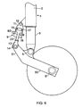
- FIG. 6 Another embodiment of the invention shown in Figure 6 is similar to the embodiment of Figure 1 , and the same reference numerals are used for similar components.
- the bogie beam 4 of Figure 1 is replaced by a beam with an aft arm 50 carrying the wheel 7', and a forward arm 51 (which does not carry a wheel) carrying a load reacting unit 9.
- the load reacting unit 9 has an upper connector 11, an upper pivot 12 for pivotally connecting the upper connector to the upper portion of the shock absorber strut 2, a lower connector 13, and a lower pivot 14 for pivotally connecting the lower connector to the forward arm 51.
- a telescopic unit comprising cylinder casing 10, piston 15 and piston rod 23 contains fluid for reacting to load applied between the upper and lower connectors, and a pressure indicator or sensor 60 is provided for monitoring the pressure in the fluid.
- a hydraulic circuit is also provided to react the tensile loading and compensate for fluid loss or differential displacement areas.
- the upper chamber 17 may be connected to atmospheric pressure.
- FIG 7 Another embodiment of the invention is illustrated in Figure 7 , as applied to a rocking bogie landing gear fitted with a pitch trimmer 80 to control the position of the bogie on landing.
- Rotation of the bogie about the pivot 5 on landing is resisted by the pitch trimmer 80, which increases the hydraulic pressure of one or more internal chambers.
- a landing load indicator 60 is provided in the pitch trimmer 80 to be responsive to the internal hydraulic pressure, and may be designed to operate in a similar manner to the indicator 60 described in the earlier embodiments.
- the pitch trimmer 60 will not experience reaction loads as large as those of the load reaction units 9 in Figures 1 and 6 but the same operating principles apply.
- the landing load indicator in Figure 7 may be adapted to be responsive to speed of reaction movement in the pitch trimmer.
- a differential pressure within the pitch trimmer might be monitored representing a rate of flow of hydraulic fluid and thus a reaction movement.
- a sensor signal generated by the indicator is monitored to detect reaction movements corresponding to a heavy landing.
- the pitch trimmer 80 in Figure 7 may be connected between the aft end of the bogie 4 and the lower portion 3 of the shock absorber strut.
Landscapes
- Engineering & Computer Science (AREA)
- Mechanical Engineering (AREA)
- Aviation & Aerospace Engineering (AREA)
- General Engineering & Computer Science (AREA)
- Physics & Mathematics (AREA)
- General Physics & Mathematics (AREA)
- Chemical & Material Sciences (AREA)
- Combustion & Propulsion (AREA)
- Force Measurement Appropriate To Specific Purposes (AREA)
- Vehicle Body Suspensions (AREA)
- Fluid-Damping Devices (AREA)
Description
- The present invention relates to load detection in a landing gear for an aircraft.
- It is desirable to monitor the loading applied to a landing gear during an overload landing in order to determine whether the designed strength level has been exceeded, or is in danger of being exceeded.
- It is also desirable to monitor the landing load during a normal landing in order to assess the fatigue loading applied to the gear.
- According to the invention, a landing gear for an aircraft comprises a shock absorber strut with upper and lower telescoping portions, the upper portion being connectable to the airframe of the aircraft; an arm to extend fore and aft relative to the aircraft and carrying a landing wheel, and pivotally connected by a main pivot to the lower portion of the shock absorber strut; and a load reacting unit connected between the arm and the shock absorber strut for reacting to load applied between the arm and shock absorber strut on landing, and an indicator for monitoring the load applied to the load reacting unit on landing.
- Furthermore, the invention relates to a method of monitoring the load on a landing gear as claimed in
claim 19. - The invention recognises that friction from sliding bearings in the shock absorber strut make a significant difference to the load for a given shock absorber internal pressure (or alternatively the shock absorber pressure may be different for the same applied load, depending upon bearing friction). Bearing friction is highly variable, depending upon the coefficient of friction and the load applied normal to the bearings.
- Thus the invention recognises that more accurate measurement of load can be made by measuring the load in the load reacting unit, which is less affected by friction than the shock absorber strut. That is, in a fluid pressure load reacting unit the pressure is much more closely related to the load applied to the arm than is the pressure in the shock absorber strut.
- The load reacting unit may be pin-jointed, or mounted on spherical bearings at each end, resulting in minimal loading normal to its sliding bearings.
- The fluid may be air (or another gas), but more preferably is a liquid.
- In the embodiments described below, the arm, may be the arm of semi-levered landing gear, and/or a bogie beam with fore and aft landing wheels.
- The invention will now be described by way of example with reference to the accompanying drawings in which:
-
EP1041001 , the closest prior art, discloses the preamble of independent claim 1. It shows a semi-levered landing gear including a main strut and pivotal bogie arrangement. An auxiliary strut including a lock-up valve is connected between the main strut and one end of the bogie, arranged to lock up at in intermediate length on take off. When the main strut extends, the locked auxiliary strut causes the landing gear to tilt into a nose-up configuration. -
Figure 1 is a schematic drawing of a semi-levered landing gear for an aircraft according to a first embodiment of the invention; -
Figure 2 is a section through the indicator inFigure 1 shown in the non-operated state; -
Figure 3 is a section similar to that ofFigure 2 showing the indicator partially operated; -
Figure 4 is a section similar toFigure 2 showing the indicator fully operated; -
Figure 5 is a schematic drawing showing various electronic components connected to the pressure sensor; -
Figure 6 is a schematic drawing of a semi-levered landing gear for an aircraft according to a second embodiment of the invention; and -
Figure 7 is a schematic drawing of a rocking bogie landing gear for an aircraft according to a third embodiment of the invention. - The landing gear illustrated in
Figure 1 comprises a main hydraulic shock absorber strut 1 comprising anupper portion 2 connectable to the underside of an aircraft at its upper end, and a lower portion 3 which telescopes within theupper portion 2 during take-off and landing. Abogie beam 4 extends fore and aft of the aircraft and is pivotally connected to the bottom of the lower portion 3 by amain pivot 5 in the mid-region of thebogie beam 4.Axles 6, 6' are mounted at each end of thebogie beam 4 and carrywheels 7, 7'. The internal construction of the main strut 1 is not shown inFigure 1 but it may take a conventional form such as shown inGB1510554 - A
load reacting unit 9 is connected between theupper portion 2 of the main strut and the forward section of thebogie beam 4 to control the angular position of the bogie beam during taxiing, take-off and landing. Theunit 9 comprises anouter cylinder casing 10 with a closed upper end carrying anupper connector 11 which is pivotally connected at 12 to theupper end 2 of the main strut. Apiston rod 23 extends from the lower end of thecylinder casing 10 and carries alower connector 13 which is pivotally connected at 14 to the front end of the bogie beam between theaxle 6 and themain pivot 5. A side stay (not shown) is connected between theupper portion 2 of the shock absorber strut and the aircraft, and moves with the strut when the landing gear is moved to a stowed position in the aircraft by a stowing actuator (not shown). - The
load reacting unit 9 has apiston 15 within thecylinder casing 10 that divides the internal space into ahigh pressure chamber 16 on one side of the piston and alow pressure chamber 17 on the other side of the piston with aninternal shoulder 18 between the twochambers chamber 16. Thepiston rod 23 extends through anaxial aperture 19 in the piston and carries aretainer 20 at its inner end to hold thepiston 15 captive on therod 23. A tensile force applied between theconnectors piston 15 and for the two to move together in acting against the high pressure fluid, which flows in a hydraulic control circuit including ahigh pressure port 21 with a flow restrictor. When the applied tensile force is released, therod 23 andpiston 15 return to the position shown inFigure 1 with thepiston 15 seating against theshoulder 18, and therod 23 will extend further into thelower pressure chamber 17 if moved further by thebogie beam 4. Thelow pressure chamber 17 is connected into the control circuit via alow pressure port 22. - In an alternative embodiment of the invention, movement of the
piston 15 andpiston rod 23 with the tensile load may be accommodated by valving in the piston to allow the flow of oil between thechambers - In operation, the
bogie beam 4 is tilted into the position shown inFigure 1 with the rear wheel 17' contacting the ground on landing. Thebogie beam 4 then rotates anticlockwise, thereby compressing the strut 1. The high pressure in theload reacting unit 9 ensures that there is little or no extension ofunit 9. The shortening of the strut 1 continues until theforward wheel 7 makes contact with the ground, thereby relieving the tensile load in theunit 9. Theload reacting unit 9 then contracts to accommodate the shortening of the main strut 1. The main strut 1 then functions as a conventional shock absorber. - Thus on landing, the
load reacting unit 9 is pressurised, and the pressure can be taken as indicative of the landing load. Therefore, alanding load indicator 60 is provided in theunit 9 to be responsive to the internal fluid pressure. Theindicator 60 shown inFigure 2 comprises abobbin 62 that is a slide fit in abore 63 of abody 64 that is exposed at an inner end to the fluid pressure and opens to the exterior of theunit 9 for inspection by service engineers. Thebobbin 62 is sealed in thebore 63 by an O-ring seal 65 seated in anannular groove 66 in the bobbin. In order to limit movement of thebobbin 62 in thebore 63, a spring-loadeddetent 67 is mounted in alateral bore 68 in thebody 64 so as to be urged towards thebore 63. The detent 67 has a rounded end formed by a ball 67' which engages a profiled surface of thebobbin 62. The profile consists of twoannular grooves 69, 69' spaced apart by a barrel-shaped shoulder 70 over which the rounded end of the detent 67 rides as the bobbin moves from the normal retracted position ofFigure 2 to an extended overload indicating position ofFigure 4 . The barrel shape of theshoulder 70 ensures a controlled movement of thebobbin 62 with increasing pressure as shown inFigure 3 , and the force of the engagement of the detent 67 with the bobbin once it has passed the crown of the barrel-shaped shoulder 70 serves to assist operation to the extended position. Once the indicator has been operated, the force of engagement of the detent in the groove 69' is sufficient to hold the bobbin in place under increased internal fluid pressure. - The
bobbin 62 is preferably painted a bright colour to increase its visibility once operated. Thebobbin 62 may be reset by manual depression or, if needed, a special tool or key may be provided. - The invention makes use of the close correlation between the pressure in the
load reaction unit 9 and the load on theaft axle 4, on touchdown. The bearing friction for theauxiliary actuator 9 will be small, because it is mounted onspherical bearings bogie pivot 5 and seal friction will also exist, but can be shown to be small. Furthermore the bogie will always be rotating in the same direction during initial compression on landing. Therefore the results can be compensated to account for the mean friction value, with the only remaining error being due to a variation in friction. - The appropriate pressure threshold value at which the indicator operates may be determined after taking into account the normal aircraft attitude and landing gear geometry, acceptable landing gear load limits, and an allowance for variations or tolerances.
- A
single indicator 60 may be provided in theload reaction unit 9 to give an indication of the occurrence of an overload condition during landing. Alternatively, two ormore indicators 60 may be provided, each set to operate at a different internal fluid pressure so that different load thresholds can be indicated. For example, two indicators can between them define an indicator range with one operating at a lower pressure and the other at a higher pressure. Different indicators may serve to trigger different inspection and safety procedures. Alternatively,multiple indicators 60 may be set to operate at slightly different pressures to reduce error margins due to tolerances. - In an alternative embodiment of the invention, the
indicator 60 may comprise a pressure sensor rather than a mechanical pressure threshold indicator. Means may be provided to monitor pressure variations and to indicate when a threshold has been exceeded. -
Figure 5 is a schematic representation of a load detection system which incorporates apressure sensor 60 comprising a load transducer with an electrical output corresponding to sensed pressure in theload reacting unit 9. - The output of the pressure sensor is received by a processor 75 which records the raw pressure data in a
store 73. Simple geometry determines a relationship between the load in theunit 9 and the load applied to the aft axle by using a method such as comparing moments about the shock absorber to bogie pivot. This relationship is predetermined and stored in a.recordeddata store 72, enabling the processor 75 to derive a value indicative of the load applied to the aft axle from the pressure data and store the aft axle load values in thestore 73. - The processor 75 may be set to determine whether the output of the pressure sensor, or a value derived therefrom (such as the aft axle load) has exceeded a pre-set threshold.
- A potential drawback is that the moment about the
bogie pivot 5 depends upon the direction of the load at the aft axle as well as its magnitude. Thus theprocessor 73 makes assumptions about the load direction based upon real-time data received from sensors such as aircraft attitude sensor 71, and pre-recorded data such as runway coefficient of friction, rolling stock inertia stored inpre-recorded data store 72. In this way, the processor 75 calculates the direction of the load applied to the aft axle and processes the measured direction to calculate a load value. - Also, the movement about the
bogie axle 5 is dependent upon the coefficient of friction between the tyre of thewheel 7 and the runway on touchdown. In order to compensate for this variation, the recordeddata store 72 may include a database of airport runway coefficient of friction values compensated for weather conditions. Alternatively, the system may make use of coefficient of friction data transmitted by another aircraft having just landed on the same runway. Alternatively, tyre spin-up rates may be measured, for example, by comparing spin-up time with ground speed and known rolling stock inertia, to determine coefficient of friction. Alternatively, coefficient of friction may be determined through the drag loading on a landing gear. - The measurement of load in the load reacting unit 9 (and hence aft axle load) may be used as part of a comprehensive load measuring system. The load measurement may be processed by the processor 75 in combination with the results from other sensors in order to obtain a more complete indication of all the loads applied.
- A
display device 74 can display a variety of indications, including the raw pressure data, the aft axle load data, or simply an indication of an overload landing when the pressure has exceeded the pre-set threshold. - Another embodiment of the invention shown in
Figure 6 is similar to the embodiment ofFigure 1 , and the same reference numerals are used for similar components. Thebogie beam 4 ofFigure 1 is replaced by a beam with anaft arm 50 carrying the wheel 7', and a forward arm 51 (which does not carry a wheel) carrying aload reacting unit 9. Theload reacting unit 9 has anupper connector 11, anupper pivot 12 for pivotally connecting the upper connector to the upper portion of theshock absorber strut 2, alower connector 13, and alower pivot 14 for pivotally connecting the lower connector to theforward arm 51. A telescopic unit comprisingcylinder casing 10,piston 15 andpiston rod 23 contains fluid for reacting to load applied between the upper and lower connectors, and a pressure indicator orsensor 60 is provided for monitoring the pressure in the fluid. A hydraulic circuit is also provided to react the tensile loading and compensate for fluid loss or differential displacement areas. Theupper chamber 17 may be connected to atmospheric pressure. - Another embodiment of the invention is illustrated in
Figure 7 , as applied to a rocking bogie landing gear fitted with apitch trimmer 80 to control the position of the bogie on landing. Rotation of the bogie about thepivot 5 on landing is resisted by thepitch trimmer 80, which increases the hydraulic pressure of one or more internal chambers. Alanding load indicator 60 is provided in thepitch trimmer 80 to be responsive to the internal hydraulic pressure, and may be designed to operate in a similar manner to theindicator 60 described in the earlier embodiments. Thepitch trimmer 60 will not experience reaction loads as large as those of theload reaction units 9 inFigures 1 and6 but the same operating principles apply. - In another embodiment of the invention, the landing load indicator in
Figure 7 may be adapted to be responsive to speed of reaction movement in the pitch trimmer. For example, a differential pressure within the pitch trimmer might be monitored representing a rate of flow of hydraulic fluid and thus a reaction movement. A sensor signal generated by the indicator is monitored to detect reaction movements corresponding to a heavy landing. - In other embodiments of the invention, the
pitch trimmer 80 inFigure 7 may be connected between the aft end of thebogie 4 and the lower portion 3 of the shock absorber strut.
Claims (25)
- A landing gear for an aircraft comprising:a shock absorber strut (1) with upper and lower telescoping portions (2, 3), the upper portion (2) being connectable to the airframe of the aircraft;an arm (4) to extend fore and aft relative to the aircraft and carrying a landing wheel(7, 7'), and pivotally connected by a main pivot (5) to the lower portion (3) of the shock absorber strut (1); anda load reacting unit (9) connected between the arm (4) and the shock absorber strut (1) for reacting to load applied between the arm (4) and shock absorber strut (1) on landing, andan indicator (60);characterised in that the indicator (60) monitors the load applied to the load reacting unit (9) on landing.
- A landing gear as claimed in claim 1 in which the load reacting unit (9) is connected between a forward end of the arm (4) and the upper portion (2) of the shock absorber strut (1) and serves to make the gear act as a semi-levered landing gear.
- A landing gear as claims in claim 1 in which the load reacting unit (9) is connected between the arm (4) and the lower portion (3) of the shock absorber strut (1) to act as a pitch trimmer.
- A landing gear as claimed in claim 3 in which the load reacting unit (9) is connected between the forward end of the arm (4) and the lower portion (3) of the shock absorber.
- A landing gear as claimed in any preceding claim wherein the arm (4) comprises a bogie beam with fore and aft landing wheels (7, 7') with the main pivot therebetween.
- A landing gear as claimed in any one of the preceding claims in which the load reacting unit (9) comprises a fluid pressure unit and the indicator (60) is responsive to pressure in the unit.
- A landing gear as claimed in claim 6 in which the indicator (60) comprises a mechanical indicator exposed to pressure in the unit so as to be operated at a predetermined pressure threshold.
- A landing gear as claimed in claim 7 in which the mechanical indicator cooperates with a spring-loaded detent that defines a normal position and an operated position of the indicator.
- A landing gear as claimed in claim 5 or 6 comprising two or more indicators set to operate at different threshold pressures.
- A landing gear as claimed in claim 6 in which the indicator (60) comprises a pressure sensor generating an output signal in accordance with sensed pressure.
- A landing gear as claimed in claim 10 further comprising means for recording the output of the pressure sensor.
- A landing gear as claimed in claim 11 further comprising means for determining whether the output of the pressure sensor, or a value derived therefrom, has exceeded a pre-set threshold.
- A landing gear as claimed in claim 6 in which the indicator (60) comprises a hydraulic sensor generating an output signal in accordance with the speed of reaction movement in the load reacting unit (9).
- A landing gear as claimed in any preceding claim wherein one or both of pivots connecting the load reacting unit (9) to the arm (4) and shock absorber strut (1) comprise spherical bearings.
- A landing gear as claimed in any preceding claim wherein one or both of pivots connecting the load reacting unit (9) to the arm (4) and shock absorber strut (1) comprise pin joints.
- A landing gear as claimed in claim 9 further comprising a load calculator for processing the output of the pressure sensor to calculate a value indicative of the load applied to the arm (4).
- A landing gear as claimed in claim 16 further comprising a sensor for sensing the direction of the load applied to the arm (4) and generating an output which is processed by the load calculator to calculate a value indicative of the load applied to the arm (4).
- A landing gear as claimed in claim 17 wherein the sensor for sensing the direction of the load applied to the arm (4) comprises an aircraft attitude sensor.
- A method of monitoring the load on a landing gear for an aircraft comprising:a shock absorber strut (1) with upper and lower telescoping portions (2, 3), the upper portion (2) being connectable to the airframe of the aircraft;an arm (4) to extend fore and aft relative to the aircraft and carrying a landing wheel (7, 7'), and a main pivot (5) pivotally connecting the arm (4) to the lower portion (3) of the shock absorber strut (1); anda load reacting unit (9) with a first connector, a first pivot for pivotally connecting the first connector to the shock absorber strut (1) or to the airframe, a second connector, a second pivot for pivotally connecting the second connector to the arm, a telescopic unit (9) for reacting to load applied between the first and second connectors,characterised by the method comprising monitoring the reaction load in the telescopic unit (9).
- A method as claimed in claim 19 further comprising measuring a fluid pressure in the telescopic unit (9) and processing the measurement to calculate a value indicative of the load applied to the arm (4).
- A method as claimed in claim 20 further comprising measuring the direction of the load applied to the arm (4) and processing the measured direction to calculate the value indicative of the load applied to the arm (4).
- A method as claimed in any of claims 19 to 21 further comprising measuring the pressure and recording the measured pressure, or a value derived therefrom.
- A method as claimed in any of claims 19 to 21 further comprising measuring the pressure and displaying the measured pressure, or a value derived from the measured pressure.
- A method as claimed in any of claims 19 to 23 further comprising measuring the pressure and determining whether the measurement, or a value derived therefrom, has exceeded a pre-set threshold.
- A method as claimed in claim 19 further comprising monitoring a pressure in the telescopic unit (9) and generating an output signal in accordance with the speed of reaction movement in the telescopic unit (9).
Applications Claiming Priority (2)
| Application Number | Priority Date | Filing Date | Title |
|---|---|---|---|
| GB0719732.0A GB2453554B (en) | 2007-10-09 | 2007-10-09 | Load detection in an aircraft landing gear |
| PCT/EP2008/063743 WO2009047367A2 (en) | 2007-10-09 | 2008-10-13 | Load detection in an aircraft landing gear |
Publications (2)
| Publication Number | Publication Date |
|---|---|
| EP2195237A2 EP2195237A2 (en) | 2010-06-16 |
| EP2195237B1 true EP2195237B1 (en) | 2013-02-27 |
Family
ID=38787879
Family Applications (1)
| Application Number | Title | Priority Date | Filing Date |
|---|---|---|---|
| EP08836934A Active EP2195237B1 (en) | 2007-10-09 | 2008-10-13 | Load detection in an aircraft landing gear |
Country Status (10)
| Country | Link |
|---|---|
| US (1) | US20100288878A1 (en) |
| EP (1) | EP2195237B1 (en) |
| JP (1) | JP5252514B2 (en) |
| CN (1) | CN101821162B (en) |
| BR (1) | BRPI0818602A2 (en) |
| ES (1) | ES2408006T3 (en) |
| GB (1) | GB2453554B (en) |
| IL (1) | IL204797A0 (en) |
| RU (1) | RU2478525C2 (en) |
| WO (1) | WO2009047367A2 (en) |
Families Citing this family (62)
| Publication number | Priority date | Publication date | Assignee | Title |
|---|---|---|---|---|
| GB2452938B (en) * | 2007-09-19 | 2011-08-10 | Messier Dowty Ltd | Load indicator |
| GB2465397C (en) * | 2008-11-17 | 2013-04-10 | Messier Dowty Ltd | Load indicator |
| GB2469804B (en) | 2009-04-27 | 2013-08-21 | Messier Dowty Ltd | Bearing assembly |
| US7946165B2 (en) * | 2009-05-05 | 2011-05-24 | Goodrich Corporation | Over-speed, rough loads and hard landing detection system |
| US8903572B1 (en) * | 2009-08-11 | 2014-12-02 | The Boeing Company | Aircraft landing evaluation system |
| US8616146B2 (en) * | 2010-03-05 | 2013-12-31 | Goodrich Corporation | System for indicating an airplane hard landing |
| US8448900B2 (en) * | 2010-03-24 | 2013-05-28 | The Boeing Company | Semi-levered landing gear and associated method |
| FR2959207B1 (en) * | 2010-04-26 | 2012-04-20 | Eurocopter France | ENERGY-ABSORPTION SYSTEM FOR AN ATTERISSEUR, AND AIRCRAFT PROVIDED WITH SAID ENERGY ABSORPTION SYSTEM |
| US8933713B2 (en) * | 2010-07-19 | 2015-01-13 | Goodrich Corporation | Capacitive sensors for monitoring loads |
| GB2483472B (en) * | 2010-09-08 | 2012-08-15 | Messier Dowty Ltd | Aircraft landing gear |
| US10131419B2 (en) | 2010-10-15 | 2018-11-20 | Goodrich Corporation | Systems and methods for detecting landing gear ground loads |
| US9481452B2 (en) | 2010-11-22 | 2016-11-01 | The Boeing Company | Hydraulic actuator for semi levered landing gear |
| GB2485803B (en) * | 2010-11-24 | 2013-02-06 | Messier Dowty Ltd | Mechanical position indicator |
| US8939400B2 (en) | 2011-02-21 | 2015-01-27 | The Boeing Company | Air-ground detection system for semi-levered landing gear |
| US8862377B2 (en) * | 2011-03-31 | 2014-10-14 | Sikorsky Aircraft Corporation | Method and system for detecting forces on aircraft |
| US8998133B2 (en) * | 2011-04-01 | 2015-04-07 | The Boeing Company | Landing gear system |
| GB2489058B (en) * | 2011-08-22 | 2013-05-08 | Messier Dowty Ltd | Aircraft landing gear |
| GB2496426B (en) * | 2011-11-11 | 2013-12-25 | Messier Dowty Ltd | Gauge |
| FR2983829B1 (en) * | 2011-12-07 | 2014-01-31 | Messier Bugatti Dowty | LANDING ROD FOR AIRCRAFT |
| CN103258105A (en) * | 2012-02-17 | 2013-08-21 | 中国航空工业集团公司沈阳飞机设计研究所 | Calculation method for service life consumption of undercarriage |
| CN103523210A (en) * | 2012-07-06 | 2014-01-22 | 哈尔滨飞机工业集团有限责任公司 | Friction shimmy damping device of nose landing gear |
| CN103818548B (en) * | 2012-11-16 | 2016-08-10 | 哈尔滨飞机工业集团有限责任公司 | Adaptive All Terrain Helicopter Landing Gear |
| CN103033380B (en) * | 2012-12-11 | 2015-07-01 | 中国飞机强度研究所 | Landing gear retractable test loading method |
| GB2510412C (en) * | 2013-02-04 | 2021-08-25 | Messier Dowty Ltd | Aircraft landing gear pitch trimmer actuator with variable damping |
| KR200467824Y1 (en) | 2013-02-21 | 2013-07-05 | (주) 코마코 | Landing gear lever for aircraft |
| US9221556B2 (en) * | 2013-10-29 | 2015-12-29 | The Boeing Company | Airplane off ground advisory system |
| CN103983438B (en) * | 2014-04-17 | 2017-02-01 | 中国航空工业集团公司沈阳飞机设计研究所 | Method for testing service life of turning control system of airplane |
| US9652902B2 (en) * | 2014-07-24 | 2017-05-16 | Goodrich Corporation | Pitch trim actuator servicing monitoring system |
| GB2532270B (en) | 2014-11-14 | 2017-05-10 | Ge Aviat Systems Ltd | An aircraft assembly with load and position indicator |
| CN105438497A (en) * | 2015-11-26 | 2016-03-30 | 中国航空工业集团公司沈阳飞机设计研究所 | Electric driving landing gear loading device |
| CN105607524B (en) * | 2016-03-16 | 2018-04-13 | 中国飞机强度研究所 | One kind has led the vertical sensor output switch method of remote signal device of false wheel |
| EP3248869B1 (en) | 2016-05-25 | 2018-09-12 | AIRBUS HELICOPTERS DEUTSCHLAND GmbH | Retraction / extension of a landing gear in an aircraft |
| US10384769B2 (en) * | 2017-01-06 | 2019-08-20 | Goodrich Corporation | Two stage strut allowing low initial compression load |
| US10384767B2 (en) | 2017-01-25 | 2019-08-20 | The Boeing Company | Single axle, semi-levered landing gear with shortening mechanism |
| FR3062636B1 (en) * | 2017-02-03 | 2021-04-16 | Safran Landing Systems | AIRCRAFT LANDING |
| US10625849B2 (en) | 2017-04-11 | 2020-04-21 | The Boeing Company | Levered landing gear with inner shock strut |
| US10549848B2 (en) * | 2017-04-26 | 2020-02-04 | Safran Landing Systems Canada Inc. | Deployable and retractable shock strut |
| GB2569768A (en) * | 2017-05-15 | 2019-07-03 | Airbus Operations Ltd | Shock absorber dimension |
| GB2562781A (en) * | 2017-05-25 | 2018-11-28 | Airbus Operations Ltd | Landing gear bogie pitch trimmer |
| US10800516B2 (en) | 2017-06-02 | 2020-10-13 | The Boeing Company | Semi-levered shrink landing gear |
| GB2563945A (en) * | 2017-06-30 | 2019-01-02 | Airbus Operations Ltd | Aircraft landing gear assembly |
| GB2563948A (en) | 2017-06-30 | 2019-01-02 | Airbus Operations Ltd | Aircraft landing gear assembly |
| GB2563949A (en) * | 2017-06-30 | 2019-01-02 | Airbus Operations Ltd | Aircraft landing gear assembly |
| FR3072943B1 (en) * | 2017-10-27 | 2021-12-10 | Safran Landing Systems | AIRCRAFT LANDING WITH BRAKED WHEELS AND MOTORIZED WHEELS |
| US11161599B2 (en) | 2018-01-26 | 2021-11-02 | The Boeing Company | Landing gear strut assembly and method therefor |
| US10981646B2 (en) | 2018-07-30 | 2021-04-20 | The Boeing Company | Landing gear shrink link mechanism |
| US10625876B2 (en) * | 2018-08-08 | 2020-04-21 | Aurora Flight Sciences Corporation | Aircraft landing systems and methods for monitoring a vertical landing of an aircraft |
| CA3060756A1 (en) * | 2018-11-07 | 2020-05-07 | Bombardier Inc. | Hard landing indicator for an aircraft landing gear |
| CN109606713B (en) * | 2018-12-03 | 2022-08-02 | 江西洪都航空工业集团有限责任公司 | Pure mechanical heavy landing indicating structure |
| CN109684678B (en) * | 2018-12-04 | 2023-04-18 | 中国航空工业集团公司西安飞机设计研究所 | Fatigue load optimization processing method for multi-wheel multi-support undercarriage in full-machine fatigue test |
| CN109506819B (en) * | 2018-12-13 | 2020-06-05 | 贵州贵航飞机设计研究所 | Method for monitoring impact load of undercarriage during landing of airplane |
| CN110274823B (en) * | 2019-06-28 | 2020-07-24 | 郑州航空工业管理学院 | Airport runway test flight experimental device |
| CN111097716B (en) * | 2019-12-25 | 2022-05-10 | 昆山孚思格机电科技有限公司 | Chain type force measuring separator reference end extension driving and overload protection method |
| GB2600150B (en) * | 2020-10-23 | 2022-12-28 | Airbus Operations Ltd | Aircraft landing gear shock absorber |
| GB2602150A (en) * | 2020-12-21 | 2022-06-22 | Airbus Operations Ltd | An aircraft landing gear |
| GB2605160B (en) * | 2021-03-24 | 2023-05-31 | Safran Landing Systems Uk Ltd | Aircraft landing gear torque link assembly |
| CN114510066B (en) * | 2022-01-26 | 2022-11-08 | 广东工业大学 | Tilt rotor heavy-load logistics unmanned aerial vehicle control system |
| US11939045B2 (en) * | 2022-04-27 | 2024-03-26 | The Boeing Company | Landing gear assembly for an aircraft, a landing gear system, and a method |
| US11892052B2 (en) * | 2022-05-06 | 2024-02-06 | Goodrich Corporation | Temperature compensated shock strut visual health indicator systems and methods |
| CN114705470B (en) * | 2022-06-07 | 2022-08-26 | 中国飞机强度研究所 | Impact loading system and method for aircraft impact strength resistance test |
| US12043408B2 (en) * | 2022-12-05 | 2024-07-23 | Goodrich Corporation | Aircraft hard landing indicator |
| CA3218700A1 (en) * | 2022-12-05 | 2024-06-05 | Goodrich Corporation | Aircraft hard landing indicator |
Family Cites Families (22)
| Publication number | Priority date | Publication date | Assignee | Title |
|---|---|---|---|---|
| US2579180A (en) * | 1949-03-15 | 1951-12-18 | Cons Vultee Aircraft Corp | Tandem-wheel shock absorbing aircraft landing gear |
| US2826381A (en) * | 1954-03-26 | 1958-03-11 | Lockheed Aircraft Corp | Landing gear for aircraft |
| GB1006522A (en) * | 1963-10-08 | 1965-10-06 | Electro Hydraulics Ltd | Retractable undercarriages for aircraft |
| GB1510554A (en) | 1976-03-31 | 1978-05-10 | British Aircraft Corp Ltd | Aircraft undercarriage unit |
| CA1127191A (en) * | 1978-10-13 | 1982-07-06 | L. Dale Coad | Viscous spring damper |
| US4296897A (en) * | 1979-01-22 | 1981-10-27 | The Boeing Company | Brake torque limiter |
| FR2616410B1 (en) * | 1987-06-09 | 1992-08-21 | Messier Hispano Sa | TIPPING BEAM LANDING DEVICE |
| DE69312687T2 (en) * | 1992-02-07 | 1998-02-26 | C. Kirk Arlington Tex. Nance | INDICATORS OF WEIGHT AND FOCUS ON AIRCRAFT |
| FR2699886B1 (en) * | 1992-12-28 | 1995-03-24 | Messier Bugatti | Liftable undercarriage, especially for large aircraft. |
| CN2309284Y (en) * | 1997-07-08 | 1999-03-03 | 马金山 | Shock-absorbing leg for undercarriage |
| IL138399A (en) * | 1998-03-19 | 2004-01-04 | Goodrich Co B F | Dual mode positioner for an aircraft landing gear axle beam |
| US6182925B1 (en) * | 1999-03-30 | 2001-02-06 | The Boeing Company | Semi-levered landing gear and auxiliary strut therefor |
| US6575405B2 (en) * | 1999-03-30 | 2003-06-10 | The Boeing Company | Control system and method for a semi-levered landing gear for an aircraft |
| JP2003054496A (en) * | 2001-08-09 | 2003-02-26 | Mitsubishi Heavy Ind Ltd | Leg part structure for aircraft |
| US6676075B2 (en) * | 2001-08-30 | 2004-01-13 | The Boeing Company | Airplane hard landing indication system |
| US7193530B2 (en) * | 2005-03-29 | 2007-03-20 | Nance C Kirk | Aircraft landing gear automated inspection and life limitation escalation system and method |
| US7274310B1 (en) * | 2005-03-29 | 2007-09-25 | Nance C Kirk | Aircraft landing gear kinetic energy monitor |
| CA2509742A1 (en) * | 2005-06-10 | 2006-12-10 | Messier-Dowty Inc. | System and method for determining aircraft hard landing events from inertial and aircraft reference frame data |
| GB0515359D0 (en) * | 2005-07-26 | 2005-08-31 | Airbus Uk Ltd | Landing gear |
| GB2428650B (en) * | 2005-08-04 | 2011-01-12 | Messier Dowty Ltd | Landing gear |
| GB0517351D0 (en) * | 2005-08-24 | 2005-10-05 | Airbus Uk Ltd | Landing load monitor for aircraft landing gear |
| US7815143B2 (en) * | 2006-08-11 | 2010-10-19 | The Boeing Company | Aircraft landing gear truck orientation for noise reduction |
-
2007
- 2007-10-09 GB GB0719732.0A patent/GB2453554B/en active Active
-
2008
- 2008-10-13 US US12/682,529 patent/US20100288878A1/en not_active Abandoned
- 2008-10-13 CN CN200880111096.1A patent/CN101821162B/en not_active Expired - Fee Related
- 2008-10-13 ES ES08836934T patent/ES2408006T3/en active Active
- 2008-10-13 WO PCT/EP2008/063743 patent/WO2009047367A2/en not_active Ceased
- 2008-10-13 JP JP2010528433A patent/JP5252514B2/en not_active Expired - Fee Related
- 2008-10-13 EP EP08836934A patent/EP2195237B1/en active Active
- 2008-10-13 RU RU2010113906/11A patent/RU2478525C2/en not_active IP Right Cessation
- 2008-10-13 BR BRPI0818602 patent/BRPI0818602A2/en not_active IP Right Cessation
-
2010
- 2010-03-28 IL IL204797A patent/IL204797A0/en unknown
Also Published As
| Publication number | Publication date |
|---|---|
| WO2009047367A2 (en) | 2009-04-16 |
| IL204797A0 (en) | 2010-11-30 |
| ES2408006T3 (en) | 2013-06-17 |
| JP5252514B2 (en) | 2013-07-31 |
| GB2453554A (en) | 2009-04-15 |
| CN101821162A (en) | 2010-09-01 |
| BRPI0818602A2 (en) | 2015-04-22 |
| GB2453554B (en) | 2012-03-14 |
| US20100288878A1 (en) | 2010-11-18 |
| EP2195237A2 (en) | 2010-06-16 |
| CN101821162B (en) | 2013-06-05 |
| RU2010113906A (en) | 2011-11-20 |
| WO2009047367A3 (en) | 2009-11-12 |
| GB0719732D0 (en) | 2007-11-21 |
| RU2478525C2 (en) | 2013-04-10 |
| JP2011504829A (en) | 2011-02-17 |
Similar Documents
| Publication | Publication Date | Title |
|---|---|---|
| US20100288878A1 (en) | Load detection in an aircraft landing gear | |
| CA2700546C (en) | Load detection in an aircraft landing gear | |
| RU2416548C2 (en) | System and method of control over undecarriage leg load, aircraft undecarriage leg, and aircraft with said system | |
| US7274310B1 (en) | Aircraft landing gear kinetic energy monitor | |
| US6237406B1 (en) | Aircraft weight and center of gravity indicator | |
| US5548517A (en) | Aircraft weight and center of gravity indicator | |
| US7967244B2 (en) | Onboard aircraft weight and balance system | |
| US20190016319A1 (en) | Aircraft landing gear assembly | |
| US7274309B2 (en) | Aircraft landing gear initial touch-down velocity monitor | |
| EP2614001B1 (en) | Aircraft landing gear | |
| EP3715811B1 (en) | Systems and methods for measuring landing gear stroke for prognostic and health management | |
| US20190002092A1 (en) | Aircraft landing gear assembly | |
| EP3360796B1 (en) | Hard-landing detection system | |
| EP3165469B1 (en) | Aircraft landing gear shock strut fluid adjustment assisting system and method | |
| EP4015373B1 (en) | Hard-landing detection system | |
| US11235887B2 (en) | Aircraft landing gear assembly | |
| CN114728692A (en) | Trend monitoring of shock absorber condition | |
| WO1996007087A1 (en) | Aircraft weight and center of gravity indicator | |
| CN112683516A (en) | Method and device for monitoring fluid content of shock absorption strut of undercarriage | |
| CN117699002A (en) | Landing gear wheel bearing state detection method and device | |
| IL126573A (en) | Aircraft weight and center of gravity indicator |
Legal Events
| Date | Code | Title | Description |
|---|---|---|---|
| PUAI | Public reference made under article 153(3) epc to a published international application that has entered the european phase |
Free format text: ORIGINAL CODE: 0009012 |
|
| 17P | Request for examination filed |
Effective date: 20100329 |
|
| AK | Designated contracting states |
Kind code of ref document: A2 Designated state(s): AT BE BG CH CY CZ DE DK EE ES FI FR GB GR HR HU IE IS IT LI LT LU LV MC MT NL NO PL PT RO SE SI SK TR |
|
| AX | Request for extension of the european patent |
Extension state: AL BA MK RS |
|
| DAX | Request for extension of the european patent (deleted) | ||
| 17Q | First examination report despatched |
Effective date: 20111018 |
|
| GRAP | Despatch of communication of intention to grant a patent |
Free format text: ORIGINAL CODE: EPIDOSNIGR1 |
|
| GRAS | Grant fee paid |
Free format text: ORIGINAL CODE: EPIDOSNIGR3 |
|
| GRAA | (expected) grant |
Free format text: ORIGINAL CODE: 0009210 |
|
| AK | Designated contracting states |
Kind code of ref document: B1 Designated state(s): AT BE BG CH CY CZ DE DK EE ES FI FR GB GR HR HU IE IS IT LI LT LU LV MC MT NL NO PL PT RO SE SI SK TR |
|
| REG | Reference to a national code |
Ref country code: GB Ref legal event code: FG4D |
|
| REG | Reference to a national code |
Ref country code: CH Ref legal event code: EP |
|
| REG | Reference to a national code |
Ref country code: AT Ref legal event code: REF Ref document number: 598350 Country of ref document: AT Kind code of ref document: T Effective date: 20130315 |
|
| REG | Reference to a national code |
Ref country code: IE Ref legal event code: FG4D |
|
| REG | Reference to a national code |
Ref country code: DE Ref legal event code: R096 Ref document number: 602008022580 Country of ref document: DE Effective date: 20130425 |
|
| REG | Reference to a national code |
Ref country code: ES Ref legal event code: FG2A Ref document number: 2408006 Country of ref document: ES Kind code of ref document: T3 Effective date: 20130617 |
|
| REG | Reference to a national code |
Ref country code: AT Ref legal event code: MK05 Ref document number: 598350 Country of ref document: AT Kind code of ref document: T Effective date: 20130227 |
|
| REG | Reference to a national code |
Ref country code: LT Ref legal event code: MG4D |
|
| PG25 | Lapsed in a contracting state [announced via postgrant information from national office to epo] |
Ref country code: BG Free format text: LAPSE BECAUSE OF FAILURE TO SUBMIT A TRANSLATION OF THE DESCRIPTION OR TO PAY THE FEE WITHIN THE PRESCRIBED TIME-LIMIT Effective date: 20130527 Ref country code: IS Free format text: LAPSE BECAUSE OF FAILURE TO SUBMIT A TRANSLATION OF THE DESCRIPTION OR TO PAY THE FEE WITHIN THE PRESCRIBED TIME-LIMIT Effective date: 20130627 Ref country code: LT Free format text: LAPSE BECAUSE OF FAILURE TO SUBMIT A TRANSLATION OF THE DESCRIPTION OR TO PAY THE FEE WITHIN THE PRESCRIBED TIME-LIMIT Effective date: 20130227 Ref country code: NO Free format text: LAPSE BECAUSE OF FAILURE TO SUBMIT A TRANSLATION OF THE DESCRIPTION OR TO PAY THE FEE WITHIN THE PRESCRIBED TIME-LIMIT Effective date: 20130527 Ref country code: SE Free format text: LAPSE BECAUSE OF FAILURE TO SUBMIT A TRANSLATION OF THE DESCRIPTION OR TO PAY THE FEE WITHIN THE PRESCRIBED TIME-LIMIT Effective date: 20130227 Ref country code: AT Free format text: LAPSE BECAUSE OF FAILURE TO SUBMIT A TRANSLATION OF THE DESCRIPTION OR TO PAY THE FEE WITHIN THE PRESCRIBED TIME-LIMIT Effective date: 20130227 |
|
| REG | Reference to a national code |
Ref country code: NL Ref legal event code: VDEP Effective date: 20130227 |
|
| PG25 | Lapsed in a contracting state [announced via postgrant information from national office to epo] |
Ref country code: PT Free format text: LAPSE BECAUSE OF FAILURE TO SUBMIT A TRANSLATION OF THE DESCRIPTION OR TO PAY THE FEE WITHIN THE PRESCRIBED TIME-LIMIT Effective date: 20130627 Ref country code: LV Free format text: LAPSE BECAUSE OF FAILURE TO SUBMIT A TRANSLATION OF THE DESCRIPTION OR TO PAY THE FEE WITHIN THE PRESCRIBED TIME-LIMIT Effective date: 20130227 Ref country code: BE Free format text: LAPSE BECAUSE OF FAILURE TO SUBMIT A TRANSLATION OF THE DESCRIPTION OR TO PAY THE FEE WITHIN THE PRESCRIBED TIME-LIMIT Effective date: 20130227 Ref country code: SI Free format text: LAPSE BECAUSE OF FAILURE TO SUBMIT A TRANSLATION OF THE DESCRIPTION OR TO PAY THE FEE WITHIN THE PRESCRIBED TIME-LIMIT Effective date: 20130227 Ref country code: GR Free format text: LAPSE BECAUSE OF FAILURE TO SUBMIT A TRANSLATION OF THE DESCRIPTION OR TO PAY THE FEE WITHIN THE PRESCRIBED TIME-LIMIT Effective date: 20130528 Ref country code: PL Free format text: LAPSE BECAUSE OF FAILURE TO SUBMIT A TRANSLATION OF THE DESCRIPTION OR TO PAY THE FEE WITHIN THE PRESCRIBED TIME-LIMIT Effective date: 20130227 Ref country code: FI Free format text: LAPSE BECAUSE OF FAILURE TO SUBMIT A TRANSLATION OF THE DESCRIPTION OR TO PAY THE FEE WITHIN THE PRESCRIBED TIME-LIMIT Effective date: 20130227 |
|
| PG25 | Lapsed in a contracting state [announced via postgrant information from national office to epo] |
Ref country code: HR Free format text: LAPSE BECAUSE OF FAILURE TO SUBMIT A TRANSLATION OF THE DESCRIPTION OR TO PAY THE FEE WITHIN THE PRESCRIBED TIME-LIMIT Effective date: 20130227 |
|
| PG25 | Lapsed in a contracting state [announced via postgrant information from national office to epo] |
Ref country code: NL Free format text: LAPSE BECAUSE OF FAILURE TO SUBMIT A TRANSLATION OF THE DESCRIPTION OR TO PAY THE FEE WITHIN THE PRESCRIBED TIME-LIMIT Effective date: 20130227 Ref country code: DK Free format text: LAPSE BECAUSE OF FAILURE TO SUBMIT A TRANSLATION OF THE DESCRIPTION OR TO PAY THE FEE WITHIN THE PRESCRIBED TIME-LIMIT Effective date: 20130227 Ref country code: EE Free format text: LAPSE BECAUSE OF FAILURE TO SUBMIT A TRANSLATION OF THE DESCRIPTION OR TO PAY THE FEE WITHIN THE PRESCRIBED TIME-LIMIT Effective date: 20130227 Ref country code: SK Free format text: LAPSE BECAUSE OF FAILURE TO SUBMIT A TRANSLATION OF THE DESCRIPTION OR TO PAY THE FEE WITHIN THE PRESCRIBED TIME-LIMIT Effective date: 20130227 Ref country code: CZ Free format text: LAPSE BECAUSE OF FAILURE TO SUBMIT A TRANSLATION OF THE DESCRIPTION OR TO PAY THE FEE WITHIN THE PRESCRIBED TIME-LIMIT Effective date: 20130227 Ref country code: RO Free format text: LAPSE BECAUSE OF FAILURE TO SUBMIT A TRANSLATION OF THE DESCRIPTION OR TO PAY THE FEE WITHIN THE PRESCRIBED TIME-LIMIT Effective date: 20130227 |
|
| PG25 | Lapsed in a contracting state [announced via postgrant information from national office to epo] |
Ref country code: CY Free format text: LAPSE BECAUSE OF FAILURE TO SUBMIT A TRANSLATION OF THE DESCRIPTION OR TO PAY THE FEE WITHIN THE PRESCRIBED TIME-LIMIT Effective date: 20130227 |
|
| PLBE | No opposition filed within time limit |
Free format text: ORIGINAL CODE: 0009261 |
|
| STAA | Information on the status of an ep patent application or granted ep patent |
Free format text: STATUS: NO OPPOSITION FILED WITHIN TIME LIMIT |
|
| 26N | No opposition filed |
Effective date: 20131128 |
|
| PGFP | Annual fee paid to national office [announced via postgrant information from national office to epo] |
Ref country code: ES Payment date: 20131017 Year of fee payment: 6 |
|
| REG | Reference to a national code |
Ref country code: DE Ref legal event code: R097 Ref document number: 602008022580 Country of ref document: DE Effective date: 20131128 |
|
| PG25 | Lapsed in a contracting state [announced via postgrant information from national office to epo] |
Ref country code: MC Free format text: LAPSE BECAUSE OF FAILURE TO SUBMIT A TRANSLATION OF THE DESCRIPTION OR TO PAY THE FEE WITHIN THE PRESCRIBED TIME-LIMIT Effective date: 20130227 |
|
| REG | Reference to a national code |
Ref country code: CH Ref legal event code: PL |
|
| REG | Reference to a national code |
Ref country code: IE Ref legal event code: MM4A |
|
| PG25 | Lapsed in a contracting state [announced via postgrant information from national office to epo] |
Ref country code: LI Free format text: LAPSE BECAUSE OF NON-PAYMENT OF DUE FEES Effective date: 20131031 Ref country code: CH Free format text: LAPSE BECAUSE OF NON-PAYMENT OF DUE FEES Effective date: 20131031 |
|
| PG25 | Lapsed in a contracting state [announced via postgrant information from national office to epo] |
Ref country code: IT Free format text: LAPSE BECAUSE OF NON-PAYMENT OF DUE FEES Effective date: 20131013 |
|
| PG25 | Lapsed in a contracting state [announced via postgrant information from national office to epo] |
Ref country code: IE Free format text: LAPSE BECAUSE OF NON-PAYMENT OF DUE FEES Effective date: 20131013 |
|
| PG25 | Lapsed in a contracting state [announced via postgrant information from national office to epo] |
Ref country code: TR Free format text: LAPSE BECAUSE OF FAILURE TO SUBMIT A TRANSLATION OF THE DESCRIPTION OR TO PAY THE FEE WITHIN THE PRESCRIBED TIME-LIMIT Effective date: 20130227 |
|
| PG25 | Lapsed in a contracting state [announced via postgrant information from national office to epo] |
Ref country code: HU Free format text: LAPSE BECAUSE OF FAILURE TO SUBMIT A TRANSLATION OF THE DESCRIPTION OR TO PAY THE FEE WITHIN THE PRESCRIBED TIME-LIMIT; INVALID AB INITIO Effective date: 20081013 Ref country code: LU Free format text: LAPSE BECAUSE OF NON-PAYMENT OF DUE FEES Effective date: 20131013 |
|
| PG25 | Lapsed in a contracting state [announced via postgrant information from national office to epo] |
Ref country code: MT Free format text: LAPSE BECAUSE OF FAILURE TO SUBMIT A TRANSLATION OF THE DESCRIPTION OR TO PAY THE FEE WITHIN THE PRESCRIBED TIME-LIMIT Effective date: 20130227 |
|
| REG | Reference to a national code |
Ref country code: FR Ref legal event code: PLFP Year of fee payment: 8 |
|
| REG | Reference to a national code |
Ref country code: ES Ref legal event code: FD2A Effective date: 20151126 |
|
| PG25 | Lapsed in a contracting state [announced via postgrant information from national office to epo] |
Ref country code: ES Free format text: LAPSE BECAUSE OF NON-PAYMENT OF DUE FEES Effective date: 20141014 |
|
| REG | Reference to a national code |
Ref country code: FR Ref legal event code: PLFP Year of fee payment: 9 |
|
| REG | Reference to a national code |
Ref country code: FR Ref legal event code: CD Owner name: SAFRAN LANDING SYSTEMS UK LTD, GB Effective date: 20170404 |
|
| REG | Reference to a national code |
Ref country code: FR Ref legal event code: PLFP Year of fee payment: 10 |
|
| REG | Reference to a national code |
Ref country code: FR Ref legal event code: PLFP Year of fee payment: 11 |
|
| PGFP | Annual fee paid to national office [announced via postgrant information from national office to epo] |
Ref country code: GB Payment date: 20210922 Year of fee payment: 14 |
|
| PGFP | Annual fee paid to national office [announced via postgrant information from national office to epo] |
Ref country code: DE Payment date: 20210921 Year of fee payment: 14 |
|
| REG | Reference to a national code |
Ref country code: DE Ref legal event code: R119 Ref document number: 602008022580 Country of ref document: DE |
|
| GBPC | Gb: european patent ceased through non-payment of renewal fee |
Effective date: 20221013 |
|
| PG25 | Lapsed in a contracting state [announced via postgrant information from national office to epo] |
Ref country code: DE Free format text: LAPSE BECAUSE OF NON-PAYMENT OF DUE FEES Effective date: 20230503 |
|
| PG25 | Lapsed in a contracting state [announced via postgrant information from national office to epo] |
Ref country code: GB Free format text: LAPSE BECAUSE OF NON-PAYMENT OF DUE FEES Effective date: 20221013 |
|
| PGFP | Annual fee paid to national office [announced via postgrant information from national office to epo] |
Ref country code: FR Payment date: 20251022 Year of fee payment: 18 |