EP2195210B1 - Electronic control system and method for preventing unauthorized starting, use or movement of an automotive vehicle, vehicle equipped with such a system - Google Patents
Electronic control system and method for preventing unauthorized starting, use or movement of an automotive vehicle, vehicle equipped with such a system Download PDFInfo
- Publication number
- EP2195210B1 EP2195210B1 EP07849048.9A EP07849048A EP2195210B1 EP 2195210 B1 EP2195210 B1 EP 2195210B1 EP 07849048 A EP07849048 A EP 07849048A EP 2195210 B1 EP2195210 B1 EP 2195210B1
- Authority
- EP
- European Patent Office
- Prior art keywords
- signal
- unit
- sub
- park
- value
- Prior art date
- Legal status (The legal status is an assumption and is not a legal conclusion. Google has not performed a legal analysis and makes no representation as to the accuracy of the status listed.)
- Active
Links
Images


Classifications
-
- B—PERFORMING OPERATIONS; TRANSPORTING
- B60—VEHICLES IN GENERAL
- B60R—VEHICLES, VEHICLE FITTINGS, OR VEHICLE PARTS, NOT OTHERWISE PROVIDED FOR
- B60R25/00—Fittings or systems for preventing or indicating unauthorised use or theft of vehicles
- B60R25/01—Fittings or systems for preventing or indicating unauthorised use or theft of vehicles operating on vehicle systems or fittings, e.g. on doors, seats or windscreens
- B60R25/04—Fittings or systems for preventing or indicating unauthorised use or theft of vehicles operating on vehicle systems or fittings, e.g. on doors, seats or windscreens operating on the propulsion system, e.g. engine or drive motor
-
- B—PERFORMING OPERATIONS; TRANSPORTING
- B60—VEHICLES IN GENERAL
- B60R—VEHICLES, VEHICLE FITTINGS, OR VEHICLE PARTS, NOT OTHERWISE PROVIDED FOR
- B60R25/00—Fittings or systems for preventing or indicating unauthorised use or theft of vehicles
- B60R25/01—Fittings or systems for preventing or indicating unauthorised use or theft of vehicles operating on vehicle systems or fittings, e.g. on doors, seats or windscreens
- B60R25/08—Fittings or systems for preventing or indicating unauthorised use or theft of vehicles operating on vehicle systems or fittings, e.g. on doors, seats or windscreens operating on brakes or brake systems
-
- B—PERFORMING OPERATIONS; TRANSPORTING
- B60—VEHICLES IN GENERAL
- B60R—VEHICLES, VEHICLE FITTINGS, OR VEHICLE PARTS, NOT OTHERWISE PROVIDED FOR
- B60R25/00—Fittings or systems for preventing or indicating unauthorised use or theft of vehicles
- B60R25/20—Means to switch the anti-theft system on or off
- B60R25/24—Means to switch the anti-theft system on or off using electronic identifiers containing a code not memorised by the user
-
- H—ELECTRICITY
- H04—ELECTRIC COMMUNICATION TECHNIQUE
- H04W—WIRELESS COMMUNICATION NETWORKS
- H04W12/00—Security arrangements; Authentication; Protecting privacy or anonymity
- H04W12/08—Access security
-
- H—ELECTRICITY
- H04—ELECTRIC COMMUNICATION TECHNIQUE
- H04W—WIRELESS COMMUNICATION NETWORKS
- H04W12/00—Security arrangements; Authentication; Protecting privacy or anonymity
- H04W12/12—Detection or prevention of fraud
- H04W12/126—Anti-theft arrangements, e.g. protection against subscriber identity module [SIM] cloning
-
- H—ELECTRICITY
- H04—ELECTRIC COMMUNICATION TECHNIQUE
- H04L—TRANSMISSION OF DIGITAL INFORMATION, e.g. TELEGRAPHIC COMMUNICATION
- H04L12/00—Data switching networks
- H04L12/28—Data switching networks characterised by path configuration, e.g. LAN [Local Area Networks] or WAN [Wide Area Networks]
- H04L12/40—Bus networks
- H04L2012/40267—Bus for use in transportation systems
- H04L2012/4028—Bus for use in transportation systems the transportation system being an aircraft
Definitions
- This invention concerns an electronic control system and a method for preventing unauthorized starting, use or movement of an automotive vehicle.
- This invention also concerns an automotive vehicle, in particular a truck, equipped with such a system.
- Security systems are used to prevent unauthorized users to start and drive a vehicle.
- An engine management system of a truck usually acts on fuelling or cranking of its internal combustion engine or on electrical supply of its electrical motor for hybrid vehicles, in order to prevent one or both of these two functions to occur if a user does not carry with him a proper Customer Identification Device or "CID", such as an electronic or mechanical key.
- CID Customer Identification Device
- the electronic or mechanical key is provided with a transponder which allows recognition of the key by a dedicated CID interaction unit located within the vehicle passenger compartment or cab.
- DE-A-102.36.957 discloses a non encrypted method for communication between a theft safeguard module and an ID receiver.
- This invention aims at providing an electronic control system which is efficient to immobilize a vehicle such as a truck even if one tries to manually start its engine in order to move it on a small distance.
- the invention can be implemented in an electronic control system for preventing unauthorized starting, use or movement of an automotive vehicle, said system comprising a customer identification device interaction unit adapted to communicate with a customer identification device in order to control access to and starting of a vehicle.
- This system is characterized in that:
- the architecture of the system allows the customer identification device, or CID, interaction unit or "key interaction unit” to efficiently communicate with one or several remotely located control units, including units acting on the fuelling, cranking and/or braking systems of the truck, with highly secured communication protocols.
- the control unit which is connected to the second auxiliary network advantageously controls an electronic park-brake of the vehicle, so that it is able to firmly immobilize said vehicle as long as a proper CID has not been recognized by the interaction unit.
- this control unit can control or belong to an air pressure management sub-system of a vehicle which provides air to pneumatic brake components.
- Said control unit can also control electronic valves and/or actuators which do not belong to the air pressure management sub-system.
- control unit connected to the second auxiliary network can control a fuelling system or a cranking system of an internal combustion engine of the vehicle.
- the data transmission means of the invention can include, for each auxiliary network, a gateway connecting this network to the main network.
- the CID interaction unit belongs to a cab input/output module of the vehicle which forms a gateway for the first auxiliary network and includes at least another control unit which grants access to the vehicle cab or passenger compartment.
- An automotive vehicle in particular a truck, can be equipped with a system as mentioned here-above.
- This invention concerns a method for preventing unauthorized starting, use or movement of an automotive vehicle, which can be implemented with a system as mentioned here-above.
- Such a method comprises at least the following steps, which are activated when a user actuates a park-brake in order to release its braking effort:
- communication between said sub-system and said park-brake control unit takes place in said vehicle via a main electronic data transmission network and first and second auxiliary electronic data transmission networks connected respectively to said interaction unit and to said park-brake control unit.
- the first signal is advantageously encrypted, on the basis of a random number, by using a logical function, and, when it decrypts said first signal in step b), said sub-system retrieves the value of said random number from said first signal.
- the second signal can be encrypted on the basis of the retrieved value of the random number, by using a logical function and, when it decrypts the second signal in step e), the control unit retrieves the value of the random number from the second signal and compares this retrieved value to the original value used to encrypt the first signal.
- the second signal is considered to be a valid signal to relieve the braking effort if and only if the original value and the value retrieved in step e) are identical or linked by a predetermined relationship.
- An electronic control system represented in figures 1 to 3 is mounted on an industrial vehicle, such as a tractor 1 adapted to haul a non-represented trailer.
- Tractor 1 is provided with an internal combustion engine 2, which is not represented in details and which is controlled by a dedicated electronic control unit 21.
- Unit 21 controls, amongst others, an injector system 22 and a set of relays 24 which pilots a cranking electrical engine 23 adapted to rotate said engine 2 in order to make it start.
- Tractor 1 is also provided with a braking system 3 which includes pneumatic braking components 31 adapted to block disks or hold drums fast in rotation with some of, and preferably all, the wheels of truck 1.
- Braking components 31 are fed with air under pressure from an air-pressure management sub-system 32 which is piloted by an electronic unit 33 comprising an electronic park-brake module.
- Items 32 and 33 can be integrated together, as explained in EP-A-1 406 805 . They can also be separated, as mentioned in US-B-6 540 308 . This invention applies to both arrangements of items 32 and 33.
- Tractor 1 is equipped with an alarm 4 which includes non-represented sensors and an electronic control unit 41.
- Tractor 1 is also provided with an access control system 5 which includes, amongst others, an immobilizer electronic control sub-module 51 coupled to an antenna 52 adapted to interact with one or several keys 6 which form customer identification devices or CID's for one or several users of tractor 1.
- an access control system 5 which includes, amongst others, an immobilizer electronic control sub-module 51 coupled to an antenna 52 adapted to interact with one or several keys 6 which form customer identification devices or CID's for one or several users of tractor 1.
- a bus runs in truck 1 and connects its different parts or sub-systems, including sub-systems 2 to 5.
- This bus forms a main electronic data transmission network No which allows information to be transmitted between electronic units and systems, in the form of electric signals.
- network No is formed of two electric lines L 1 and L 2 fixed on tractor 1.
- Communication on network No and any other network connected to this network is made with an encoded protocol which can be according to the SAE J1939 standard.
- Other standards can also be used to convey information with network No.
- auxiliary networks or sub-nets N 1 to N 7 are connected to main network No, each of them being located in one specific part of tractor 1 or dedicated to one group of functions.
- a first auxiliary network N 1 concerns the cab of tractor 1. It includes a cab input/output module or CIOM 101 which forms a gateway for the connection between networks No and N 1 and which also includes other functions to be detailed hereafter.
- CIOM 101 which forms a gateway for the connection between networks No and N 1 and which also includes other functions to be detailed hereafter.
- Several electronic devices located in the cab of tractor 1 are connected via network N 1 to module 101.
- the alarm 4 of tractor 1 is connected to module 101 via network N 1 .
- An electronic climate control (ECC) module 102, a secondary retaining system (SRS) module 103 and a safety module 104 are also connected to module 101 via network N 1 .
- ECC electronic climate control
- SRS secondary retaining system
- safety module 104 are also connected to module 101 via network N 1 .
- module 101 forms a gateway G 1 between networks No and N 1 .
- Module 101 also includes a first electronic unit U 11 which is provided with antenna 52 and which is supposed to interact with a key 6 in order to assess whether or not this key gives access to the cab of tractor 1 and allows to start and move this tractor.
- Key 6 is a customer identification device or CID and unit U 11 forms a CID interaction unit.
- Module 101 also includes another unit U 12 which pilots the door locks of the cabin.
- Module 101 also includes a third unit U 13 having switches adapted to control wipers, beams, cruise control, speed limiter and/or power take off (PTO) sub-assemblies. Units U 11 and U 12 form together sub-module 51.
- PTO power take off
- network N 1 also includes other units U 14 , U 15 , U 16 which belong to modules 102 to 104.
- the number and arrangement of units connected to network N 1 depends on the nature of the functions to be supported by this network.
- Network N 1 allows units U 11 to U 16 to exchange data, whereas gateway G 1 allows these units to exchange data with units belonging to other networks, via network No.
- a second auxiliary network or sub-net N 2 forms the chassis sub-net which is connected to network No by a vehicle master control unit or VMCU 201.
- a Fuse and Relay Center or FRC pass-through 202 is associated with VMCU 201 and allows control of power transmission within tractor 1.
- Air-pressure management sub-system 32 and electrical park-brake 33 are also connected to network N 2 .
- a cab heater 203 is also connected to sub-net N 2 , together with a tyre pressure monitoring sub-system 204 and a rear axle steering sub-system 205.
- VMCU 201 forms a second gateway G 2 which connects networks No and N 2 .
- Several electrical control units U 23 to U 26 are connected via network N 2 and can exchange electronic data.
- Unit U 23 belongs to and controls electrical park-brake 33.
- Unit U 23 can be integrated to and control the air-pressure management sub-system 32. It can also be used to control electronic valves, such as solenoid valves, and actuators which do not belong to sub-system 32 but also allow to control pneumatic components 31.
- Units U 24 to U 26 respectively belong to and control items 203 to 205.
- Gateway G 2 allows these units to exchange data with network No.
- a third auxiliary network or sub-net N3 is also connected to the main network N0 and forms the power train sub-net. Connection between auxiliary network N3 and main network N0 takes place in parallel via an engine management system (EMS) 301 and a transmission electronic unit 302.
- EMS engine management system
- a urea distribution system 303 and an anti-pollution system 304, e.g. a NOx control system are also connected between them and to units 301 and 302 via network N3.
- Either item 301 or 302 or both form a gateway G 3 which connects network N 3 to network No.
- EMS 301 comprises gateway G 3 .
- Units U 31 and U 32 belong to EMS 301. They control respectively the fueling function, via injector system 22, and the cranking function, via sub-system 23 and 24, of engine 2.
- Several other control units U 33 to U 36 are connected to this network. Each unit U 33 to U 36 can, for example, be devoted to the function of one of items 301 to 304.
- Units U 31 to U 36 and gateway G 3 belong to ECU 21.
- a Fleet Management System (FMS) network N 4 , bodybuilder proprietary network N 5 , a tachograph network N 6 and brake proprietary network N 7 are connected to the main network No via a respective dedicated gateway G 4 to G 7 .
- FMS Fleet Management System
- Gateways G 1 to G 7 do not have to know the content of the signals which go through them, provided that these gateways can read the format and receiving unit address of each signal.
- unit U 23 When the user is onboard tractor 1 and tries to release a braking effort exerted by the pneumatic braking components 31 on the disks of tractor 1, unit U 23 sends a challenge signal S 1 to interaction unit U 11 in order to get the authorization to control electronic park-brake 33 in a way to release this effort. As shown on figure 3 , transmission of challenge signal S 1 occurs via network N 2 , gateway G 2 , network No, gateway G 1 and network N 1 .
- the try of the driver to release the braking effort can be made by moving a park brake lever or park brake buttom.
- unit U 11 sends back to unit U 23 an authorization signal S 2 which is conveyed by network U 1 , gateway G 1 , network No, gateway G 2 and network N 2 .
- the gateways G 1 and G 2 , the main network No and the two auxiliary networks N 1 and N 2 of tractor 1 convey data between units U 11 and U 23 which have a dialog in order to allow or not operation of the brakes of tractor 1.
- signals S 1 and S 2 are encrypted.
- unit U 23 computes a first code C 1 on the basis of a random number N.
- a first logical or dedication function f 1 is used for the purpose of generating code C 1 on the basis of number N.
- unit U 23 creates the encrypted signal S 1 , which includes the address u 11 of unit U 11 and code C 1 , and send it on network N 1 .
- signal S 1 is received by unit U 11 which is able to retrieve the value N' of number N from code C 1 .
- unit 1003 uses a specific function g 1 which is stored in a memory of unit U 11 and which is specific to the pair of units U 11 and U 23 , these units being associated in a pair upon building of tractor 1.
- unit U 11 is able to retrieve the value N' of N in step 1003 because it has been associated to unit U 23 upon construction of tractor 1.
- unit U 11 verifies if key 6 authorizes the user to release the brakes of tractor 1.
- step 1004 unit U 11 sends to key 6 an excitation signal S 11 which is supposed to be received by a transponder integrated within key 6.
- key 6 generates a response signal S 12 which is sent back to unit U 11 and which is analyzed in a step 1006 in order to assess whether or not it can be considered as a valid signal allowing to move the tractor 1. For instance, in step 1006, signal S 12 can be compared to a list of response signals allowing use of tractor 1.
- step 1006 If signal S 12 is found to be valid in step 1006, unit U 11 generates, in a further step 1007, a second code C 2 as a function of value N'. To this purpose, unit U 11 uses a logical function or dedication function f 2 .
- code C 2 is incorporated by unit U 11 into encrypted electronic signal S 2 which incorporates the address U 23 of unit U 23 and this second code C 2 . This takes place in a further step 1008.
- Signal S 2 is then sent back to unit U 23 via network N 1 , gateway G 1 network No, gateway G 2 and network N 2 .
- unit U 11 proceeds to another step 1009 where it generates a signal S 3 incorporating the address u 23 of unit U 23 and which is different from signal S 2 insofar as it does not incorporate second code C 2 .
- This signal S 3 is then sent to unit U 23 , in the same way as signal S 2 .
- unit U 23 When it receives signal S 2 or signal S 3 , unit U 23 tries to retrieve the value N" of number N from code C 2 in a further step 1010. In step 1010, unit U 23 uses a logical function g 2 to compute the value N" of N on the basis of code C 2 . If signal S 3 is received instead of signal S 2 , it is not possible for unit U 23 to retrieve a value N" which is equal to number N.
- the value N' or N" of number N is retrieved by "subtracting” or otherwise reverse-computing this value from the encrypted code C 1 or C 2 , which is possible since functions f 1 and g 1 are matched and since functions f 2 and g 2 are also matched.
- the value N" retrieved at step 1010 is compared to the value of N used for the computation of step 1001. If these two values are identical, then unit U 23 considers that signal S 2 received from unit U 1 is an authorization signal and, in a further step 1012, it controls electrical park-brake 33 to release the braking effort due to components 31. If, on the contrary, the value N" retrieved at step 1010 does not correspond to the original value of N, then unit U 23 holds the braking effort in a further step 1013.
- the comparison at step 1011 relates to the identity of the value N" retrieved at step 1010 and the original value N of the random number.
- the successive operations obtained via functions f 1 , g 1 , f 2 and g 2 can lead to the fact that the value obtained at step 1010 is not equal to the original value of random number N but has a predetermined relationship with this original value.
- this value retrieved at step 1010 can be the double of the original value of random number N, this retrieved value being divided by two prior to the comparison of step 1011.
- the architecture of the electronic system and the successive steps of the method enhance the safety of the communication between units U 11 and U 23 .
- the invention can also be used to enhance communication between other units of the system, in particular between unit U 11 and one of units U 31 and U 32 , which allows efficient control of the fuelling and cranking of engine 2.
- the invention can be used for the interaction between unit U 11 and a one of units U 33 to U 36 or any logical units connected to networks N 4 to N 7 .
- the invention has been represented when used for a tractor of a truck. It is actually possible to use the invention for any kind of truck, including a truck with a rigid body supporting a storage compartment. It is also possible to use the invention with a passenger car. In such a case, what has been described here-above as a cab corresponds to the passenger compartment of the vehicle.
- the invention has been represented with a CID in the form of a mechanical key. It can also be used with a CID having the shape of a credit card.
Landscapes
- Engineering & Computer Science (AREA)
- Computer Security & Cryptography (AREA)
- Computer Networks & Wireless Communication (AREA)
- Signal Processing (AREA)
- Mechanical Engineering (AREA)
- Regulating Braking Force (AREA)
- Small-Scale Networks (AREA)
- Electric Propulsion And Braking For Vehicles (AREA)
Description
- This invention concerns an electronic control system and a method for preventing unauthorized starting, use or movement of an automotive vehicle. This invention also concerns an automotive vehicle, in particular a truck, equipped with such a system.
- Security systems are used to prevent unauthorized users to start and drive a vehicle. An engine management system of a truck usually acts on fuelling or cranking of its internal combustion engine or on electrical supply of its electrical motor for hybrid vehicles, in order to prevent one or both of these two functions to occur if a user does not carry with him a proper Customer Identification Device or "CID", such as an electronic or mechanical key. The electronic or mechanical key is provided with a transponder which allows recognition of the key by a dedicated CID interaction unit located within the vehicle passenger compartment or cab.
- Such known techniques are globally efficient, in particular for passengers' cars. However, they can be ineffective in some circumstances for avoiding theft of the load of a truck. Indeed, it is possible to manually connect a starter of an engine through a source of power, which can make a truck move by a few meters, this distance being sufficient to allow thieves to access to the load of a truck or to disassemble a tractor from its trailer, which can then be hauled by another tractor and taken away.
-
DE-A-102.36.957 discloses a non encrypted method for communication between a theft safeguard module and an ID receiver. - This invention aims at providing an electronic control system which is efficient to immobilize a vehicle such as a truck even if one tries to manually start its engine in order to move it on a small distance.
- the invention can be implemented in an electronic control system for preventing unauthorized starting, use or movement of an automotive vehicle, said system comprising a customer identification device interaction unit adapted to communicate with a customer identification device in order to control access to and starting of a vehicle. This system is characterized in that:
- it comprises a main electronic data transmission network and at least two auxiliary electronic data transmission networks connected to said main network,
- said customer identification device interaction unit is connected to a first auxiliary network, and
- said system comprises data transmission means adapted to convey, via said main network, information data between said interaction unit and at least one control unit of said vehicle connected to a second auxiliary network.
- The architecture of the system allows the customer identification device, or CID, interaction unit or "key interaction unit" to efficiently communicate with one or several remotely located control units, including units acting on the fuelling, cranking and/or braking systems of the truck, with highly secured communication protocols.
- The control unit which is connected to the second auxiliary network advantageously controls an electronic park-brake of the vehicle, so that it is able to firmly immobilize said vehicle as long as a proper CID has not been recognized by the interaction unit. In such a case, this control unit can control or belong to an air pressure management sub-system of a vehicle which provides air to pneumatic brake components. Said control unit can also control electronic valves and/or actuators which do not belong to the air pressure management sub-system.
- Alternatively, the control unit connected to the second auxiliary network can control a fuelling system or a cranking system of an internal combustion engine of the vehicle.
- The data transmission means of the invention can include, for each auxiliary network, a gateway connecting this network to the main network.
- According to a further aspect, the CID interaction unit belongs to a cab input/output module of the vehicle which forms a gateway for the first auxiliary network and includes at least another control unit which grants access to the vehicle cab or passenger compartment.
- An automotive vehicle, in particular a truck, can be equipped with a system as mentioned here-above.
- This invention concerns a method for preventing unauthorized starting, use or movement of an automotive vehicle, which can be implemented with a system as mentioned here-above. Such a method comprises at least the following steps, which are activated when a user actuates a park-brake in order to release its braking effort:
- a) a park-brake control unit sends a first encrypted challenge signal to a sub-system including a CID interaction unit
- b) said sub-system decrypts said first message,
- c) if said interaction unit has identified a CID device as valid to start, use or move said vehicle, said sub-system sends to said park-brake control unit a second encrypted message including instructions to release said braking effort,
- d) if said interaction unit has not identified a CID as valid to start, use or move the vehicle, said sub-system sends to said park-brake control unit a third message different from said second encrypted message,
- e) said park-brake control unit decrypts said second or third message and releases said braking effort if and only if said second message is identified as including said instructions.
- Advantageously, communication between said sub-system and said park-brake control unit takes place in said vehicle via a main electronic data transmission network and first and second auxiliary electronic data transmission networks connected respectively to said interaction unit and to said park-brake control unit.
- The first signal is advantageously encrypted, on the basis of a random number, by using a logical function, and, when it decrypts said first signal in step b), said sub-system retrieves the value of said random number from said first signal. In such a case, the second signal can be encrypted on the basis of the retrieved value of the random number, by using a logical function and, when it decrypts the second signal in step e), the control unit retrieves the value of the random number from the second signal and compares this retrieved value to the original value used to encrypt the first signal.
- Then, one can foresee that the second signal is considered to be a valid signal to relieve the braking effort if and only if the original value and the value retrieved in step e) are identical or linked by a predetermined relationship.
- The invention will be better understood on the basis of the following description, which is given in correspondence with the annexed figures and as an illustrative example, without restricting the object of the invention which is defined by the appended claims. In the annexed figures:
-
figure 1 is a general schematic view of a truck tractor including an electronic control system, -
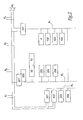
figure 2 is a partial electric scheme of the electronic control system of the tractor offigure 1 , -
figure 3 is a partial logical scheme of the system offigure 2 , and -
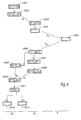
figure 4 is a block diagram of a method according to the invention. - An electronic control system represented in
figures 1 to 3 is mounted on an industrial vehicle, such as atractor 1 adapted to haul a non-represented trailer.Tractor 1 is provided with aninternal combustion engine 2, which is not represented in details and which is controlled by a dedicatedelectronic control unit 21. -
Unit 21 controls, amongst others, aninjector system 22 and a set ofrelays 24 which pilots a crankingelectrical engine 23 adapted to rotate saidengine 2 in order to make it start. - Tractor 1 is also provided with a braking system 3 which includes
pneumatic braking components 31 adapted to block disks or hold drums fast in rotation with some of, and preferably all, the wheels oftruck 1.Braking components 31 are fed with air under pressure from an air-pressure management sub-system 32 which is piloted by anelectronic unit 33 comprising an electronic park-brake module.Items EP-A-1 406 805 . They can also be separated, as mentioned inUS-B-6 540 308 . This invention applies to both arrangements ofitems - Tractor 1 is equipped with an
alarm 4 which includes non-represented sensors and anelectronic control unit 41. - Tractor 1 is also provided with an
access control system 5 which includes, amongst others, an immobilizerelectronic control sub-module 51 coupled to anantenna 52 adapted to interact with one orseveral keys 6 which form customer identification devices or CID's for one or several users oftractor 1. - A bus runs in
truck 1 and connects its different parts or sub-systems, includingsub-systems 2 to 5. This bus forms a main electronic data transmission network No which allows information to be transmitted between electronic units and systems, in the form of electric signals. As shown infigure 2 , network No is formed of two electric lines L1 and L2 fixed ontractor 1. Communication on network No and any other network connected to this network is made with an encoded protocol which can be according to the SAE J1939 standard. One can use a "challenge/response technique". Other standards can also be used to convey information with network No. - Several auxiliary networks or sub-nets N1 to N7 are connected to main network No, each of them being located in one specific part of
tractor 1 or dedicated to one group of functions. - A first auxiliary network N1 concerns the cab of
tractor 1. It includes a cab input/output module orCIOM 101 which forms a gateway for the connection between networks No and N1 and which also includes other functions to be detailed hereafter. Several electronic devices located in the cab oftractor 1 are connected via network N1 tomodule 101. Thealarm 4 oftractor 1 is connected tomodule 101 via network N1. An electronic climate control (ECC)module 102, a secondary retaining system (SRS)module 103 and asafety module 104 are also connected tomodule 101 via network N1. In fact, as shown onfigure 3 ,module 101 forms a gateway G1 between networks No and N1. Module 101 also includes a first electronic unit U11 which is provided withantenna 52 and which is supposed to interact with a key 6 in order to assess whether or not this key gives access to the cab oftractor 1 and allows to start and move this tractor.Key 6 is a customer identification device or CID and unit U11 forms a CID interaction unit.Module 101 also includes another unit U12 which pilots the door locks of the cabin.Module 101 also includes a third unit U13 having switches adapted to control wipers, beams, cruise control, speed limiter and/or power take off (PTO) sub-assemblies. Units U11 and U12 form together sub-module 51. - Next to units U11 to U13, which belong to
module 101, network N1 also includes other units U14, U15, U16 which belong tomodules 102 to 104. The number and arrangement of units connected to network N1 depends on the nature of the functions to be supported by this network. - Network N1 allows units U11 to U16 to exchange data, whereas gateway G1 allows these units to exchange data with units belonging to other networks, via network No.
- A second auxiliary network or sub-net N2 forms the chassis sub-net which is connected to network No by a vehicle master control unit or
VMCU 201. A Fuse and Relay Center or FRC pass-through 202 is associated withVMCU 201 and allows control of power transmission withintractor 1. Air-pressure management sub-system 32 and electrical park-brake 33 are also connected to network N2.A cab heater 203 is also connected to sub-net N2, together with a tyrepressure monitoring sub-system 204 and a rearaxle steering sub-system 205. As shown onfigure 3 ,VMCU 201 forms a second gateway G2 which connects networks No and N2. Several electrical control units U23 to U26 are connected via network N2 and can exchange electronic data. Unit U23 belongs to and controls electrical park-brake 33. Unit U23 can be integrated to and control the air-pressure management sub-system 32. It can also be used to control electronic valves, such as solenoid valves, and actuators which do not belong to sub-system 32 but also allow to controlpneumatic components 31. - Units U24 to U26 respectively belong to and control
items 203 to 205. - Data can be exchanged between units U23 to U26 via network N2. Gateway G2 allows these units to exchange data with network No.
- A third auxiliary network or sub-net N3 is also connected to the main network N0 and forms the power train sub-net. Connection between auxiliary network N3 and main network N0 takes place in parallel via an engine management system (EMS) 301 and a transmission
electronic unit 302. Aurea distribution system 303 and ananti-pollution system 304, e.g. a NOx control system are also connected between them and tounits - Either
item figure 3 , one considers thatEMS 301 comprises gateway G3. Units U31 and U32 belong toEMS 301. They control respectively the fueling function, viainjector system 22, and the cranking function, viasub-system engine 2. Several other control units U33 to U36 are connected to this network. Each unit U33 to U36 can, for example, be devoted to the function of one ofitems 301 to 304. Units U31 to U36 and gateway G3 belong toECU 21. - A Fleet Management System (FMS) network N4, bodybuilder proprietary network N5, a tachograph network N6 and brake proprietary network N7 are connected to the main network No via a respective dedicated gateway G4 to G7.
- When a user wants to access
tractor 1, he opens the door of the tractor cab with hiskey 6. Interaction between the door lock and the key can be contactless if the door lock is provided with an antenna adapted to excite a transponder located withinkey 6. - Gateways G1 to G7 do not have to know the content of the signals which go through them, provided that these gateways can read the format and receiving unit address of each signal.
- When the user is
onboard tractor 1 and tries to release a braking effort exerted by thepneumatic braking components 31 on the disks oftractor 1, unit U23 sends a challenge signal S1 to interaction unit U11 in order to get the authorization to control electronic park-brake 33 in a way to release this effort. As shown onfigure 3 , transmission of challenge signal S1 occurs via network N2, gateway G2, network No, gateway G1 and network N1. - The try of the driver to release the braking effort can be made by moving a park brake lever or park brake buttom.
- If
key 6 is present and is identified as authorizing the user to drivetractor 1, unit U11 sends back to unit U23 an authorization signal S2 which is conveyed by network U1, gateway G1, network No, gateway G2 and network N2. - Therefore, the gateways G1 and G2, the main network No and the two auxiliary networks N1 and N2 of
tractor 1 convey data between units U11 and U23 which have a dialog in order to allow or not operation of the brakes oftractor 1. - In order to enhance security for the communication between units U23 and U11, signals S1 and S2 are encrypted.
- In a
first step 1001 of the method of the invention, unit U23 computes a first code C1 on the basis of a random number N. A first logical or dedication function f1 is used for the purpose of generating code C1 on the basis of number N. In asecond step 1002, unit U23 creates the encrypted signal S1, which includes the address u11 of unit U11 and code C1, and send it on network N1. In athird step 1003, signal S1 is received by unit U11 which is able to retrieve the value N' of number N from code C1. For this purpose,unit 1003 uses a specific function g1 which is stored in a memory of unit U11 and which is specific to the pair of units U11 and U23, these units being associated in a pair upon building oftractor 1. In other words, unit U11 is able to retrieve the value N' of N instep 1003 because it has been associated to unit U23 upon construction oftractor 1. - When the value N' is retrieved, unit U11 verifies if
key 6 authorizes the user to release the brakes oftractor 1. - To this purpose, in a
further step 1004, unit U11 sends to key 6 an excitation signal S11 which is supposed to be received by a transponder integrated withinkey 6. In afurther step 1005,key 6 generates a response signal S12 which is sent back to unit U11 and which is analyzed in astep 1006 in order to assess whether or not it can be considered as a valid signal allowing to move thetractor 1. For instance, instep 1006, signal S12 can be compared to a list of response signals allowing use oftractor 1. - One should note that the verification of the fact that
key 6 allows to drivetractor 1, which takes place insteps steps step 1006. Interaction between unit U11 and key 6 can occur in any way known from "keyless" or "contactless" access systems. This interaction can be based on a communication protocol which is independent from the one taking place via network No, between units U11 and U23. - If signal S12 is found to be valid in
step 1006, unit U11 generates, in afurther step 1007, a second code C2 as a function of value N'. To this purpose, unit U11 uses a logical function or dedication function f2. - Then, code C2 is incorporated by unit U11 into encrypted electronic signal S2 which incorporates the address U23 of unit U23 and this second code C2. This takes place in a
further step 1008. Signal S2 is then sent back to unit U23 via network N1, gateway G1 network No, gateway G2 and network N2. - If signal S12 is found not be valid, then unit U11 proceeds to another
step 1009 where it generates a signal S3 incorporating the address u23 of unit U23 and which is different from signal S2 insofar as it does not incorporate second code C2. This signal S3 is then sent to unit U23, in the same way as signal S2. - When it receives signal S2 or signal S3, unit U23 tries to retrieve the value N" of number N from code C2 in a
further step 1010. Instep 1010, unit U23 uses a logical function g2 to compute the value N" of N on the basis of code C2. If signal S3 is received instead of signal S2, it is not possible for unit U23 to retrieve a value N" which is equal to number N. - In
steps - Then in a
further step 1011, the value N" retrieved atstep 1010 is compared to the value of N used for the computation ofstep 1001. If these two values are identical, then unit U23 considers that signal S2 received from unit U1 is an authorization signal and, in afurther step 1012, it controls electrical park-brake 33 to release the braking effort due tocomponents 31. If, on the contrary, the value N" retrieved atstep 1010 does not correspond to the original value of N, then unit U23 holds the braking effort in afurther step 1013. - In the examples listed here-above, the comparison at
step 1011 relates to the identity of the value N" retrieved atstep 1010 and the original value N of the random number. However, according to another embodiment of the invention, the successive operations obtained via functions f1, g1, f2 and g2 can lead to the fact that the value obtained atstep 1010 is not equal to the original value of random number N but has a predetermined relationship with this original value. For example, this value retrieved atstep 1010 can be the double of the original value of random number N, this retrieved value being divided by two prior to the comparison ofstep 1011. - The architecture of the electronic system and the successive steps of the method enhance the safety of the communication between units U11 and U23.
- The invention can also be used to enhance communication between other units of the system, in particular between unit U11 and one of units U31 and U32, which allows efficient control of the fuelling and cranking of
engine 2. Similarly, the invention can be used for the interaction between unit U11 and a one of units U33 to U36 or any logical units connected to networks N4 to N7. - Actually, some of the units and gateways represented on
figure 3 can be built together on a unique circuit board. This is the case for units U11 to U13 and gateway G1 which constitute together theCIOM 201. - The invention has been represented when used for a tractor of a truck. It is actually possible to use the invention for any kind of truck, including a truck with a rigid body supporting a storage compartment. It is also possible to use the invention with a passenger car. In such a case, what has been described here-above as a cab corresponds to the passenger compartment of the vehicle.
- The invention has been represented with a CID in the form of a mechanical key. It can also be used with a CID having the shape of a credit card.
Claims (5)
- A method for preventing unauthorized starting, use or movement of an automotive vehicle (1), comprising at least the following steps which are activated when a user actuates a park-brake (3) in order to release its braking effort:a) a park-brake control unit (U23) sends (1002) a first encrypted challenge signal (S1) to a sub-system (101) including a customer identification device interaction unit (U11), the method being characterised by the following steps:b) said sub-system (101) decrypts (1003) said first message,c) if said interaction unit (U11) has identified a customer identification device (6) as valid to start, use or move said vehicle, said sub-system sends (1008) to said park-brake control unit a second encrypted message (S2) including instructions (C2) to release said braking effort,d) if said interaction unit (U11) has not identified a customer identification device (6) as valid to start, use or move the vehicle, said sub-system sends (1009) to said park-brake control unit a third message (S3) different from said second encrypted message,e) said park-brake control unit (U11) decrypts (1010) said second or third message and releases said braking effort if and only if said second message is identified as including said instructions (N=N").
- Method according to claim 1, characterized in that communication between said sub-system (101) and said park-brake control unit (U23) takes place in said vehicle (1) via a main electronic data transmission network (N0) and first and second auxiliary electronic data transmission networks (N1, N2) connected respectively to said interaction unit (U11) and to said park-brake control unit (U23).
- Method according to one of claims 1 or 2, characterized in that said first signal (S1) is encrypted (1001, 1002), on the basis of a random number (N), by using a logical function (f1) and, when it decrypts (1003) said first signal in step b), said sub-system retrieves the value (N') of said random number from said first signal (S1).
- Method according to claim 3, characterized in that said second signal (S2) is encrypted (1007, 1008), on the basis of said retrieved value (N') of said random number (N), by using a logical function (f2), and, when it decrypts (1010) said second signal in step e), said control unit (U23) retrieves the value (N") of said random number from said second signal (C2) and compares (1011) said retrieved value (N") to the original value (N) used to encrypt said first signal.
- Method according to claim 4, characterized in that said second signal (S2) is considered to be a valid signal to release said braking effort if and only if said original value (N) and the value (N") retrieved in step e) are identical or linked by a predetermined relationship.
Applications Claiming Priority (1)
| Application Number | Priority Date | Filing Date | Title |
|---|---|---|---|
| PCT/IB2007/004175 WO2009040606A1 (en) | 2007-09-25 | 2007-09-25 | Electronic control system and method for preventing unauthorized starting, use or movement of an automotive vehicle, vehicle equipped with such a system |
Publications (2)
| Publication Number | Publication Date |
|---|---|
| EP2195210A1 EP2195210A1 (en) | 2010-06-16 |
| EP2195210B1 true EP2195210B1 (en) | 2013-04-17 |
Family
ID=39930525
Family Applications (1)
| Application Number | Title | Priority Date | Filing Date |
|---|---|---|---|
| EP07849048.9A Active EP2195210B1 (en) | 2007-09-25 | 2007-09-25 | Electronic control system and method for preventing unauthorized starting, use or movement of an automotive vehicle, vehicle equipped with such a system |
Country Status (3)
| Country | Link |
|---|---|
| EP (1) | EP2195210B1 (en) |
| BR (1) | BRPI0722136B1 (en) |
| WO (1) | WO2009040606A1 (en) |
Family Cites Families (4)
| Publication number | Priority date | Publication date | Assignee | Title |
|---|---|---|---|---|
| DE19525180C5 (en) * | 1995-07-11 | 2010-01-07 | Daimler Ag | Electronic control unit for a motor vehicle with data networks and immobilizer |
| JP3832347B2 (en) * | 2002-01-21 | 2006-10-11 | 株式会社デンソー | Vehicle anti-theft device and program |
| DE10307081A1 (en) * | 2002-02-21 | 2003-09-11 | Marquardt Gmbh | Controller for motor vehicle has compartment for mobile control part associated with control function, e.g. identification transmitter/mobile telephone, charging station for mobile control part |
| DE10236957B4 (en) * | 2002-08-13 | 2010-07-08 | Huf Hülsbeck & Fürst Gmbh & Co. Kg | Locking device for motor vehicles |
-
2007
- 2007-09-25 EP EP07849048.9A patent/EP2195210B1/en active Active
- 2007-09-25 BR BRPI0722136A patent/BRPI0722136B1/en not_active IP Right Cessation
- 2007-09-25 WO PCT/IB2007/004175 patent/WO2009040606A1/en not_active Ceased
Also Published As
| Publication number | Publication date |
|---|---|
| WO2009040606A1 (en) | 2009-04-02 |
| BRPI0722136A2 (en) | 2014-09-23 |
| BRPI0722136B1 (en) | 2018-05-08 |
| EP2195210A1 (en) | 2010-06-16 |
Similar Documents
| Publication | Publication Date | Title |
|---|---|---|
| US6346876B1 (en) | Multi-vehicle compatible control system generating command signals on a data bus and associated methods | |
| US6756885B1 (en) | Multi-vehicle compatible control system for reading from a data bus and associated methods | |
| US9456468B2 (en) | Trailer access point pairing | |
| US20030222770A1 (en) | Apparatus and method for enhanced data communications and control between a vehicle and a remote data communications terminal | |
| US7205679B2 (en) | Remote start system for a vehicle having a data communications bus and related methods | |
| US7046126B2 (en) | Vehicle window control system for a vehicle having a data communications bus and associated methods | |
| CN202827403U (en) | Vehicle controller | |
| US20070021885A1 (en) | System and method for personalizing motor vehicle ride or handling characteristics | |
| US20030150416A1 (en) | Remote start system including an engine speed data bus reader and related methods | |
| KR101875438B1 (en) | Communication control device, vehicle having the same and method for controlling the same | |
| CN104871220A (en) | A system for parking time management | |
| US20150310679A1 (en) | System allowing a service provider to selectively open a vehicle | |
| US6759942B2 (en) | Vehicle communication system implemented reusing existing vehicle components | |
| US7369936B2 (en) | Remote start control system including an engine speed data bus reader and related methods | |
| CN113492798A (en) | Apparatus and method for providing access to shared vehicles without power locks | |
| US20170197588A1 (en) | Remote function device and associated wireless security sensor for a vehicle having a data communications bus and related methods | |
| CN105034975A (en) | Vehicle door engagement detection | |
| CN108216115B (en) | System and method for controlling vehicle door lock system | |
| US20170197587A1 (en) | Remote function control system with remote function device and associated wireless security sensor for a vehicle having a data communications bus and related methods | |
| JP3589188B2 (en) | Electronic key device for vehicles | |
| EP1884420A2 (en) | Theft prevention of a vehicle by credential verification of a vehicle driver before unlocking a parking control member | |
| EP2195210A1 (en) | Electronic control system and method for preventing unauthorized starting, use or movement of an automotive vehicle, vehicle equipped with such a system | |
| EP4101705A1 (en) | Energy management system for a motor vehicle and method for managing energy in a motor vehicle | |
| CN117048551A (en) | Vehicle anti-theft control method based on EPB | |
| CA2426670C (en) | Remote start system including an engine speed data bus reader and related methods |
Legal Events
| Date | Code | Title | Description |
|---|---|---|---|
| PUAI | Public reference made under article 153(3) epc to a published international application that has entered the european phase |
Free format text: ORIGINAL CODE: 0009012 |
|
| 17P | Request for examination filed |
Effective date: 20100426 |
|
| AK | Designated contracting states |
Kind code of ref document: A1 Designated state(s): AT BE BG CH CY CZ DE DK EE ES FI FR GB GR HU IE IS IT LI LT LU LV MC MT NL PL PT RO SE SI SK TR |
|
| AX | Request for extension of the european patent |
Extension state: AL BA HR MK RS |
|
| DAX | Request for extension of the european patent (deleted) | ||
| GRAP | Despatch of communication of intention to grant a patent |
Free format text: ORIGINAL CODE: EPIDOSNIGR1 |
|
| GRAS | Grant fee paid |
Free format text: ORIGINAL CODE: EPIDOSNIGR3 |
|
| GRAA | (expected) grant |
Free format text: ORIGINAL CODE: 0009210 |
|
| AK | Designated contracting states |
Kind code of ref document: B1 Designated state(s): AT BE BG CH CY CZ DE DK EE ES FI FR GB GR HU IE IS IT LI LT LU LV MC MT NL PL PT RO SE SI SK TR |
|
| REG | Reference to a national code |
Ref country code: GB Ref legal event code: FG4D |
|
| REG | Reference to a national code |
Ref country code: CH Ref legal event code: EP |
|
| REG | Reference to a national code |
Ref country code: IE Ref legal event code: FG4D |
|
| REG | Reference to a national code |
Ref country code: AT Ref legal event code: REF Ref document number: 607068 Country of ref document: AT Kind code of ref document: T Effective date: 20130515 |
|
| REG | Reference to a national code |
Ref country code: DE Ref legal event code: R096 Ref document number: 602007029891 Country of ref document: DE Effective date: 20130613 |
|
| REG | Reference to a national code |
Ref country code: AT Ref legal event code: MK05 Ref document number: 607068 Country of ref document: AT Kind code of ref document: T Effective date: 20130417 |
|
| REG | Reference to a national code |
Ref country code: LT Ref legal event code: MG4D |
|
| REG | Reference to a national code |
Ref country code: NL Ref legal event code: VDEP Effective date: 20130417 |
|
| PG25 | Lapsed in a contracting state [announced via postgrant information from national office to epo] |
Ref country code: SE Free format text: LAPSE BECAUSE OF FAILURE TO SUBMIT A TRANSLATION OF THE DESCRIPTION OR TO PAY THE FEE WITHIN THE PRESCRIBED TIME-LIMIT Effective date: 20130417 Ref country code: SI Free format text: LAPSE BECAUSE OF FAILURE TO SUBMIT A TRANSLATION OF THE DESCRIPTION OR TO PAY THE FEE WITHIN THE PRESCRIBED TIME-LIMIT Effective date: 20130417 Ref country code: FI Free format text: LAPSE BECAUSE OF FAILURE TO SUBMIT A TRANSLATION OF THE DESCRIPTION OR TO PAY THE FEE WITHIN THE PRESCRIBED TIME-LIMIT Effective date: 20130417 Ref country code: IS Free format text: LAPSE BECAUSE OF FAILURE TO SUBMIT A TRANSLATION OF THE DESCRIPTION OR TO PAY THE FEE WITHIN THE PRESCRIBED TIME-LIMIT Effective date: 20130817 Ref country code: AT Free format text: LAPSE BECAUSE OF FAILURE TO SUBMIT A TRANSLATION OF THE DESCRIPTION OR TO PAY THE FEE WITHIN THE PRESCRIBED TIME-LIMIT Effective date: 20130417 Ref country code: ES Free format text: LAPSE BECAUSE OF FAILURE TO SUBMIT A TRANSLATION OF THE DESCRIPTION OR TO PAY THE FEE WITHIN THE PRESCRIBED TIME-LIMIT Effective date: 20130728 Ref country code: LT Free format text: LAPSE BECAUSE OF FAILURE TO SUBMIT A TRANSLATION OF THE DESCRIPTION OR TO PAY THE FEE WITHIN THE PRESCRIBED TIME-LIMIT Effective date: 20130417 Ref country code: BE Free format text: LAPSE BECAUSE OF FAILURE TO SUBMIT A TRANSLATION OF THE DESCRIPTION OR TO PAY THE FEE WITHIN THE PRESCRIBED TIME-LIMIT Effective date: 20130417 Ref country code: GR Free format text: LAPSE BECAUSE OF FAILURE TO SUBMIT A TRANSLATION OF THE DESCRIPTION OR TO PAY THE FEE WITHIN THE PRESCRIBED TIME-LIMIT Effective date: 20130718 Ref country code: PT Free format text: LAPSE BECAUSE OF FAILURE TO SUBMIT A TRANSLATION OF THE DESCRIPTION OR TO PAY THE FEE WITHIN THE PRESCRIBED TIME-LIMIT Effective date: 20130819 |
|
| PG25 | Lapsed in a contracting state [announced via postgrant information from national office to epo] |
Ref country code: BG Free format text: LAPSE BECAUSE OF FAILURE TO SUBMIT A TRANSLATION OF THE DESCRIPTION OR TO PAY THE FEE WITHIN THE PRESCRIBED TIME-LIMIT Effective date: 20130717 Ref country code: CY Free format text: LAPSE BECAUSE OF FAILURE TO SUBMIT A TRANSLATION OF THE DESCRIPTION OR TO PAY THE FEE WITHIN THE PRESCRIBED TIME-LIMIT Effective date: 20130417 Ref country code: LV Free format text: LAPSE BECAUSE OF FAILURE TO SUBMIT A TRANSLATION OF THE DESCRIPTION OR TO PAY THE FEE WITHIN THE PRESCRIBED TIME-LIMIT Effective date: 20130417 Ref country code: PL Free format text: LAPSE BECAUSE OF FAILURE TO SUBMIT A TRANSLATION OF THE DESCRIPTION OR TO PAY THE FEE WITHIN THE PRESCRIBED TIME-LIMIT Effective date: 20130417 |
|
| PG25 | Lapsed in a contracting state [announced via postgrant information from national office to epo] |
Ref country code: CZ Free format text: LAPSE BECAUSE OF FAILURE TO SUBMIT A TRANSLATION OF THE DESCRIPTION OR TO PAY THE FEE WITHIN THE PRESCRIBED TIME-LIMIT Effective date: 20130417 Ref country code: EE Free format text: LAPSE BECAUSE OF FAILURE TO SUBMIT A TRANSLATION OF THE DESCRIPTION OR TO PAY THE FEE WITHIN THE PRESCRIBED TIME-LIMIT Effective date: 20130417 Ref country code: DK Free format text: LAPSE BECAUSE OF FAILURE TO SUBMIT A TRANSLATION OF THE DESCRIPTION OR TO PAY THE FEE WITHIN THE PRESCRIBED TIME-LIMIT Effective date: 20130417 Ref country code: SK Free format text: LAPSE BECAUSE OF FAILURE TO SUBMIT A TRANSLATION OF THE DESCRIPTION OR TO PAY THE FEE WITHIN THE PRESCRIBED TIME-LIMIT Effective date: 20130417 |
|
| PLBE | No opposition filed within time limit |
Free format text: ORIGINAL CODE: 0009261 |
|
| STAA | Information on the status of an ep patent application or granted ep patent |
Free format text: STATUS: NO OPPOSITION FILED WITHIN TIME LIMIT |
|
| PG25 | Lapsed in a contracting state [announced via postgrant information from national office to epo] |
Ref country code: RO Free format text: LAPSE BECAUSE OF FAILURE TO SUBMIT A TRANSLATION OF THE DESCRIPTION OR TO PAY THE FEE WITHIN THE PRESCRIBED TIME-LIMIT Effective date: 20130417 Ref country code: IT Free format text: LAPSE BECAUSE OF FAILURE TO SUBMIT A TRANSLATION OF THE DESCRIPTION OR TO PAY THE FEE WITHIN THE PRESCRIBED TIME-LIMIT Effective date: 20130417 Ref country code: NL Free format text: LAPSE BECAUSE OF FAILURE TO SUBMIT A TRANSLATION OF THE DESCRIPTION OR TO PAY THE FEE WITHIN THE PRESCRIBED TIME-LIMIT Effective date: 20130417 |
|
| 26N | No opposition filed |
Effective date: 20140120 |
|
| PG25 | Lapsed in a contracting state [announced via postgrant information from national office to epo] |
Ref country code: MC Free format text: LAPSE BECAUSE OF FAILURE TO SUBMIT A TRANSLATION OF THE DESCRIPTION OR TO PAY THE FEE WITHIN THE PRESCRIBED TIME-LIMIT Effective date: 20130417 |
|
| REG | Reference to a national code |
Ref country code: DE Ref legal event code: R097 Ref document number: 602007029891 Country of ref document: DE Effective date: 20140120 Ref country code: CH Ref legal event code: PL |
|
| REG | Reference to a national code |
Ref country code: IE Ref legal event code: MM4A |
|
| PG25 | Lapsed in a contracting state [announced via postgrant information from national office to epo] |
Ref country code: CH Free format text: LAPSE BECAUSE OF NON-PAYMENT OF DUE FEES Effective date: 20130930 Ref country code: IE Free format text: LAPSE BECAUSE OF NON-PAYMENT OF DUE FEES Effective date: 20130925 Ref country code: LI Free format text: LAPSE BECAUSE OF NON-PAYMENT OF DUE FEES Effective date: 20130930 |
|
| REG | Reference to a national code |
Ref country code: DE Ref legal event code: R082 Ref document number: 602007029891 Country of ref document: DE Representative=s name: V. FUENER EBBINGHAUS FINCK HANO, DE |
|
| REG | Reference to a national code |
Ref country code: GB Ref legal event code: 732E Free format text: REGISTERED BETWEEN 20141229 AND 20141231 |
|
| REG | Reference to a national code |
Ref country code: DE Ref legal event code: R082 Ref document number: 602007029891 Country of ref document: DE Representative=s name: V. FUENER EBBINGHAUS FINCK HANO, DE Effective date: 20141219 Ref country code: DE Ref legal event code: R081 Ref document number: 602007029891 Country of ref document: DE Owner name: VOLVO TRUCK CORP., SE Free format text: FORMER OWNER: RENAULT TRUCKS, SAINT PRIEST, FR Effective date: 20141219 |
|
| REG | Reference to a national code |
Ref country code: FR Ref legal event code: TP Owner name: VOLVO LASTVAGNAR AKTIEBOLAG, SE Effective date: 20150209 |
|
| PG25 | Lapsed in a contracting state [announced via postgrant information from national office to epo] |
Ref country code: MT Free format text: LAPSE BECAUSE OF FAILURE TO SUBMIT A TRANSLATION OF THE DESCRIPTION OR TO PAY THE FEE WITHIN THE PRESCRIBED TIME-LIMIT Effective date: 20130417 Ref country code: TR Free format text: LAPSE BECAUSE OF FAILURE TO SUBMIT A TRANSLATION OF THE DESCRIPTION OR TO PAY THE FEE WITHIN THE PRESCRIBED TIME-LIMIT Effective date: 20130417 |
|
| PG25 | Lapsed in a contracting state [announced via postgrant information from national office to epo] |
Ref country code: HU Free format text: LAPSE BECAUSE OF FAILURE TO SUBMIT A TRANSLATION OF THE DESCRIPTION OR TO PAY THE FEE WITHIN THE PRESCRIBED TIME-LIMIT; INVALID AB INITIO Effective date: 20070925 Ref country code: LU Free format text: LAPSE BECAUSE OF NON-PAYMENT OF DUE FEES Effective date: 20130925 |
|
| REG | Reference to a national code |
Ref country code: FR Ref legal event code: PLFP Year of fee payment: 9 |
|
| REG | Reference to a national code |
Ref country code: FR Ref legal event code: PLFP Year of fee payment: 10 |
|
| REG | Reference to a national code |
Ref country code: FR Ref legal event code: PLFP Year of fee payment: 11 |
|
| REG | Reference to a national code |
Ref country code: FR Ref legal event code: PLFP Year of fee payment: 12 |
|
| PGFP | Annual fee paid to national office [announced via postgrant information from national office to epo] |
Ref country code: GB Payment date: 20190930 Year of fee payment: 13 |
|
| GBPC | Gb: european patent ceased through non-payment of renewal fee |
Effective date: 20200925 |
|
| PG25 | Lapsed in a contracting state [announced via postgrant information from national office to epo] |
Ref country code: GB Free format text: LAPSE BECAUSE OF NON-PAYMENT OF DUE FEES Effective date: 20200925 |
|
| PGFP | Annual fee paid to national office [announced via postgrant information from national office to epo] |
Ref country code: DE Payment date: 20240926 Year of fee payment: 18 |
|
| PGFP | Annual fee paid to national office [announced via postgrant information from national office to epo] |
Ref country code: FR Payment date: 20240925 Year of fee payment: 18 |