EP2195170B1 - Ink jet printer - Google Patents
Ink jet printer Download PDFInfo
- Publication number
- EP2195170B1 EP2195170B1 EP08806561.0A EP08806561A EP2195170B1 EP 2195170 B1 EP2195170 B1 EP 2195170B1 EP 08806561 A EP08806561 A EP 08806561A EP 2195170 B1 EP2195170 B1 EP 2195170B1
- Authority
- EP
- European Patent Office
- Prior art keywords
- ink
- cartridge
- data
- storage device
- printing fluid
- Prior art date
- Legal status (The legal status is an assumption and is not a legal conclusion. Google has not performed a legal analysis and makes no representation as to the accuracy of the status listed.)
- Active
Links
- 239000012530 fluid Substances 0.000 claims description 144
- 239000002904 solvent Substances 0.000 claims description 133
- 238000007639 printing Methods 0.000 claims description 86
- 238000013500 data storage Methods 0.000 claims description 75
- 238000003860 storage Methods 0.000 claims description 18
- 239000000976 ink Substances 0.000 description 367
- 238000012545 processing Methods 0.000 description 51
- 239000000758 substrate Substances 0.000 description 18
- 239000000463 material Substances 0.000 description 7
- 238000007789 sealing Methods 0.000 description 7
- 238000004891 communication Methods 0.000 description 5
- 239000006260 foam Substances 0.000 description 5
- 239000011159 matrix material Substances 0.000 description 5
- 238000003780 insertion Methods 0.000 description 4
- 230000037431 insertion Effects 0.000 description 4
- 238000007641 inkjet printing Methods 0.000 description 3
- 230000002093 peripheral effect Effects 0.000 description 3
- 238000011144 upstream manufacturing Methods 0.000 description 3
- LFQSCWFLJHTTHZ-UHFFFAOYSA-N Ethanol Chemical compound CCO LFQSCWFLJHTTHZ-UHFFFAOYSA-N 0.000 description 2
- 238000009530 blood pressure measurement Methods 0.000 description 2
- 230000000694 effects Effects 0.000 description 2
- 230000005684 electric field Effects 0.000 description 2
- 238000011010 flushing procedure Methods 0.000 description 2
- 238000004519 manufacturing process Methods 0.000 description 2
- 238000000034 method Methods 0.000 description 2
- 238000012544 monitoring process Methods 0.000 description 2
- 230000008569 process Effects 0.000 description 2
- 239000004743 Polypropylene Substances 0.000 description 1
- 230000009471 action Effects 0.000 description 1
- 230000004913 activation Effects 0.000 description 1
- 238000004140 cleaning Methods 0.000 description 1
- 230000007423 decrease Effects 0.000 description 1
- 230000001419 dependent effect Effects 0.000 description 1
- 230000009977 dual effect Effects 0.000 description 1
- 239000013536 elastomeric material Substances 0.000 description 1
- 238000009429 electrical wiring Methods 0.000 description 1
- 230000007613 environmental effect Effects 0.000 description 1
- 238000001704 evaporation Methods 0.000 description 1
- 230000008020 evaporation Effects 0.000 description 1
- 238000007654 immersion Methods 0.000 description 1
- 239000007788 liquid Substances 0.000 description 1
- 238000012986 modification Methods 0.000 description 1
- 230000004048 modification Effects 0.000 description 1
- 238000004806 packaging method and process Methods 0.000 description 1
- -1 polypropylene Polymers 0.000 description 1
- 229920001155 polypropylene Polymers 0.000 description 1
- 230000010349 pulsation Effects 0.000 description 1
- 238000005086 pumping Methods 0.000 description 1
- 238000004064 recycling Methods 0.000 description 1
- 230000008439 repair process Effects 0.000 description 1
- 238000005096 rolling process Methods 0.000 description 1
- 229920006395 saturated elastomer Polymers 0.000 description 1
- 238000000935 solvent evaporation Methods 0.000 description 1
- 239000004094 surface-active agent Substances 0.000 description 1
- 229920003051 synthetic elastomer Polymers 0.000 description 1
- 239000005061 synthetic rubber Substances 0.000 description 1
- XLYOFNOQVPJJNP-UHFFFAOYSA-N water Substances O XLYOFNOQVPJJNP-UHFFFAOYSA-N 0.000 description 1
Images


Classifications
-
- B—PERFORMING OPERATIONS; TRANSPORTING
- B41—PRINTING; LINING MACHINES; TYPEWRITERS; STAMPS
- B41J—TYPEWRITERS; SELECTIVE PRINTING MECHANISMS, i.e. MECHANISMS PRINTING OTHERWISE THAN FROM A FORME; CORRECTION OF TYPOGRAPHICAL ERRORS
- B41J2/00—Typewriters or selective printing mechanisms characterised by the printing or marking process for which they are designed
- B41J2/005—Typewriters or selective printing mechanisms characterised by the printing or marking process for which they are designed characterised by bringing liquid or particles selectively into contact with a printing material
- B41J2/01—Ink jet
- B41J2/17—Ink jet characterised by ink handling
- B41J2/175—Ink supply systems ; Circuit parts therefor
- B41J2/17503—Ink cartridges
- B41J2/17513—Inner structure
-
- B—PERFORMING OPERATIONS; TRANSPORTING
- B41—PRINTING; LINING MACHINES; TYPEWRITERS; STAMPS
- B41J—TYPEWRITERS; SELECTIVE PRINTING MECHANISMS, i.e. MECHANISMS PRINTING OTHERWISE THAN FROM A FORME; CORRECTION OF TYPOGRAPHICAL ERRORS
- B41J2/00—Typewriters or selective printing mechanisms characterised by the printing or marking process for which they are designed
- B41J2/005—Typewriters or selective printing mechanisms characterised by the printing or marking process for which they are designed characterised by bringing liquid or particles selectively into contact with a printing material
- B41J2/01—Ink jet
- B41J2/17—Ink jet characterised by ink handling
- B41J2/175—Ink supply systems ; Circuit parts therefor
- B41J2/17503—Ink cartridges
- B41J2/1752—Mounting within the printer
- B41J2/17523—Ink connection
-
- B—PERFORMING OPERATIONS; TRANSPORTING
- B41—PRINTING; LINING MACHINES; TYPEWRITERS; STAMPS
- B41J—TYPEWRITERS; SELECTIVE PRINTING MECHANISMS, i.e. MECHANISMS PRINTING OTHERWISE THAN FROM A FORME; CORRECTION OF TYPOGRAPHICAL ERRORS
- B41J2/00—Typewriters or selective printing mechanisms characterised by the printing or marking process for which they are designed
- B41J2/005—Typewriters or selective printing mechanisms characterised by the printing or marking process for which they are designed characterised by bringing liquid or particles selectively into contact with a printing material
- B41J2/01—Ink jet
- B41J2/17—Ink jet characterised by ink handling
- B41J2/175—Ink supply systems ; Circuit parts therefor
- B41J2/17503—Ink cartridges
- B41J2/17526—Electrical contacts to the cartridge
- B41J2/1753—Details of contacts on the cartridge, e.g. protection of contacts
-
- B—PERFORMING OPERATIONS; TRANSPORTING
- B41—PRINTING; LINING MACHINES; TYPEWRITERS; STAMPS
- B41J—TYPEWRITERS; SELECTIVE PRINTING MECHANISMS, i.e. MECHANISMS PRINTING OTHERWISE THAN FROM A FORME; CORRECTION OF TYPOGRAPHICAL ERRORS
- B41J2/00—Typewriters or selective printing mechanisms characterised by the printing or marking process for which they are designed
- B41J2/005—Typewriters or selective printing mechanisms characterised by the printing or marking process for which they are designed characterised by bringing liquid or particles selectively into contact with a printing material
- B41J2/01—Ink jet
- B41J2/17—Ink jet characterised by ink handling
- B41J2/175—Ink supply systems ; Circuit parts therefor
- B41J2/17503—Ink cartridges
- B41J2/17543—Cartridge presence detection or type identification
- B41J2/17546—Cartridge presence detection or type identification electronically
-
- B—PERFORMING OPERATIONS; TRANSPORTING
- B41—PRINTING; LINING MACHINES; TYPEWRITERS; STAMPS
- B41J—TYPEWRITERS; SELECTIVE PRINTING MECHANISMS, i.e. MECHANISMS PRINTING OTHERWISE THAN FROM A FORME; CORRECTION OF TYPOGRAPHICAL ERRORS
- B41J2/00—Typewriters or selective printing mechanisms characterised by the printing or marking process for which they are designed
- B41J2/005—Typewriters or selective printing mechanisms characterised by the printing or marking process for which they are designed characterised by bringing liquid or particles selectively into contact with a printing material
- B41J2/01—Ink jet
- B41J2/17—Ink jet characterised by ink handling
- B41J2/175—Ink supply systems ; Circuit parts therefor
- B41J2/17503—Ink cartridges
- B41J2/17553—Outer structure
-
- B—PERFORMING OPERATIONS; TRANSPORTING
- B41—PRINTING; LINING MACHINES; TYPEWRITERS; STAMPS
- B41J—TYPEWRITERS; SELECTIVE PRINTING MECHANISMS, i.e. MECHANISMS PRINTING OTHERWISE THAN FROM A FORME; CORRECTION OF TYPOGRAPHICAL ERRORS
- B41J2/00—Typewriters or selective printing mechanisms characterised by the printing or marking process for which they are designed
- B41J2/005—Typewriters or selective printing mechanisms characterised by the printing or marking process for which they are designed characterised by bringing liquid or particles selectively into contact with a printing material
- B41J2/01—Ink jet
- B41J2/17—Ink jet characterised by ink handling
- B41J2/175—Ink supply systems ; Circuit parts therefor
- B41J2/17566—Ink level or ink residue control
-
- B—PERFORMING OPERATIONS; TRANSPORTING
- B41—PRINTING; LINING MACHINES; TYPEWRITERS; STAMPS
- B41J—TYPEWRITERS; SELECTIVE PRINTING MECHANISMS, i.e. MECHANISMS PRINTING OTHERWISE THAN FROM A FORME; CORRECTION OF TYPOGRAPHICAL ERRORS
- B41J2/00—Typewriters or selective printing mechanisms characterised by the printing or marking process for which they are designed
- B41J2/005—Typewriters or selective printing mechanisms characterised by the printing or marking process for which they are designed characterised by bringing liquid or particles selectively into contact with a printing material
- B41J2/01—Ink jet
- B41J2/17—Ink jet characterised by ink handling
- B41J2/18—Ink recirculation systems
- B41J2/185—Ink-collectors; Ink-catchers
- B41J2002/1853—Ink-collectors; Ink-catchers ink collectors for continuous Inkjet printers, e.g. gutters, mist suction means
Description
- The present invention relates to an ink jet printer and to an ink supply system for an ink jet printer such as a continuous ink jet printer.
- In ink jet printing systems the print is made up of individual droplets of ink generated at a nozzle and propelled towards a substrate. There are two principal systems: drop on demand where ink droplets for printing are generated as and when required; and continuous ink jet printing in which droplets are continuously produced and only selected ones are directed towards the substrate, the others being recirculated to an ink supply.
- Continuous ink jet printers supply pressurised ink to a print head drop generator where a continuous stream of ink emanating from a nozzle is broken up into individual regular drops by an oscillating piezoelectric element. The drops are directed past a charge electrode where they are selectively and separately given a predetermined charge before passing through a transverse electric field provided across a pair of deflection plates. Each charged drop is deflected by the field by an amount that is dependent on its charge magnitude before impinging on the substrate whereas the uncharged drops proceed without deflection and are collected at a gutter from where they are recirculated to the ink supply for reuse. The charged drops bypass the gutter and hit the substrate at a position determined by the charge on the drop and the position of the substrate relative to the print head. Typically the substrate is moved relative to the print head in one direction and the drops are deflected in a direction generally perpendicular thereto, although the deflection plates may be oriented at an inclination to the perpendicular to compensate for the speed of the substrate (the movement of the substrate relative to the print head between drops arriving means that a line of drops would otherwise not quite extend perpendicularly to the direction of movement of the substrate).
- In continuous ink jet printing a character is printed from a matrix comprising a regular array of potential drop positions. Each matrix comprises a plurality of columns (strokes), each being defined by a line comprising a plurality of potential drop positions (e.g. seven) determined by the charge applied to the drops. Thus each usable drop is charged according to its intended position in the stroke. If a particular drop is not to be used then the drop is not charged and it is captured at the gutter for recirculation. This cycle repeats for all strokes in a matrix and then starts again for the next character matrix.
- Ink is delivered under pressure to the print head by an ink supply system that is generally housed within a sealed compartment of a cabinet that includes a separate compartment for control circuitry and a user interface panel. The system includes a main pump that draws the ink from a reservoir or tank via a filter and delivers it under pressure to the print head. As ink is consumed the reservoir is refilled as necessary from a replaceable ink cartridge that is releasably connected to the reservoir by a supply conduit. The ink is fed from the reservoir via a flexible delivery conduit to the print head. The unused ink drops captured by the gutter are recirculated to the reservoir via a return conduit by a pump. The flow of ink in each of the conduits is generally controlled by solenoid valves and/or other like components.
- As the ink circulates through the system, there is a tendency for it to thicken as a result of solvent evaporation, particularly in relation to the recirculated ink that has been exposed to air in its passage between the nozzle and the gutter. In order to compensate for this "make-up" solvent is added to the ink as required from a replaceable solvent cartridge so as to maintain the ink viscosity within desired limits. This solvent may also be used for flushing components of the print head, such as the nozzle and the gutter, in a cleaning cycle. It will be appreciated that circulation of the solvent requires further fluid conduits and therefore that the ink supply system as a whole comprises a significant number of conduits connected between different components of the ink supply system. The many connections between the components and the conduits all represent a potential source of leakage and loss of pressure. Given that continuous ink jet printers are typically used on production lines for long uninterrupted periods reliability is an important issue. Moreover, the presence of multiple conduits in the interior of the ink supply section of the cabinet makes access to certain components difficult in the event of servicing or repair.
-
US2003/206220 describes an ink jet printer. It is explained that printhead control electronics controls various printing systems. An ink container includes an information storage device and ink volume sensing circuitry. The information storage device provides information to the printer control electronics such as ink container volume and ink characteristics. -
EP1004449 describes an ink cartridge and a printer using such ink cartridge. Various pieces of information relating to the ink cartridge are stored at specific addresses on a storage element. -
US2006/127153 describes a three-dimensional object printing system which includes cartridges containing modeling materials. Sensors associated with the cartridges monitor the status of the material within the cartridges. A controller receives data about the material presently available in each cartridge and computes supply parameters for the available materials in the various cartridges. - It is one object of the present invention, amongst others, to provide for an improved or an alternative ink jet printer and/or an alternative or improved ink supply system for an ink jet printer.
- According to the present invention, there is provided an ink jet printer comprising:a printing fluid cartridge receiving portion arranged to receive a printing fluid cartridge and to allow passage of printing fluid from a received printing fluid cartridge to printing fluid conduits of the ink jet printer; a data reader arranged to read data indicating a quantity of fluid within a received cartridge from an electronic data storage device associated with the received printing fluid cartridge; and a controller arranged to determine a quantity of fluid within said printing fluid cartridge based upon a pressure within said printing fluid cartridge and to generate update data usable to modify data stored on said electronic data storage device based upon said determination and to modify data stored on said electronic storage device based upon said update data such that data stored on said electronic data storage device indicates an updated quantity of fluid in said printing fluid cartridge.
- In this way, the ink jet printer is arranged such that an electronic data storage device associated with a printing fluid cartridge stores data providing an up to date indication of the quantity of fluid within the printing fluid cartridge. As printing fluid is used, the stored data is updated. If a printing fluid cartridge is removed from a first printer and inserted into the second printer, the second printer can use data stored on the electronic data storage device to obtain an indication of a quantity of printing fluid within the printing fluid cartridge, without any assumption as to usage of the printing fluid cartridge, and without any prior knowledge of use of the printing fluid cartridge.
- The printing fluid contained in the printing fluid cartridge is typically a liquid ink or solvent.
- The controller may be arranged to determine a quantity of fluid within said printing fluid cartridge and to generate said update data based upon said determination. Determination of the quantity of fluid within the printing fluid cartridge can be carried out in any suitable way. For example the controller may be arranged to determine a quantity of fluid within said printing fluid cartridge based upon a quantity of fluid removed from said printing fluid cartridge. Determination of a quantity of fluid removed from the printing fluid cartridge may be based upon a quantity of fluid used in printing operations, for example a quantity of ink provided from a print head of the ink jet printer. The controller may be arranged to determine a quantity of fluid within said printing fluid cartridge based upon at least one property of said printing fluid cartridge and/or at least one property of fluid within said printing fluid cartridge, for example based upon a pressure within said printing fluid cartridge.
- The electronic data storage device associated with the printing fluid cartridge may store first data indicating a quantity of fluid initially stored in said printing fluid cartridge, and second data indicating a quantity of fluid removed from the printing fluid cartridge. The update data may be arranged to modify said second data. The second data may comprise a predetermined number of data elements having first and second states, each data element being associated with a predetermined quantity of ink, and said quantity of ink removed from the printing fluid cartridge may be represented by a number of data elements set to the first state. Each of the data elements may be a bit.
- Determining the update data may comprise determining a current quantity of fluid in said printing fluid cartridge; determining a difference between said initial quantity of fluid and said current quantity of fluid; and generating said update data based upon said difference.
- The data reader may be arranged to read said first data and said second data. The controller may be arranged to subtract a quantity based upon said second data from a quantity based upon said first data. The data reader may comprise a plurality of electrical contacts arranged to make contact with corresponding electrical contacts of a printing fluid cartridge.
- The printing fluid cartridge receiving portion may be a plurality of printing fluid cartridge receiving portions each arranged to receive a respective printing fluid cartridge and to allow passage of printing fluid from a received printing fluid cartridge to printing fluid conduits of the ink jet printer. The data reader may be a plurality of data readers each arranged to read data indicating a quantity of fluid within a received cartridge from a respective electronic data storage device associated with a respective received printing fluid cartridge. The controller may be arranged to generate update data usable to modify data stored on each of said electronic data storage devices, and to modify data stored on each electronic storage device based upon said update data, such that data stored on each electronic data storage device indicates an updated quantity of fluid in a respective printing fluid cartridge.
- The ink jet printer may be a continuous ink jet printer intended for industrial use. Such continuous ink jet printers have a variety of applications, including printing data such as "sell by" dates and the like onto packaging.
- The invention further provides a fluid cartridge for an ink jet printer. The fluid cartridge comprises a vessel arranged to hold printing fluid and an electronic storage device configured to hold data indicating a target pressure for the printing fluid and data indicating a quantity of printing fluid within said vessel, the electronic storage device being arranged to receive update data from an ink jet printer and to store data on said electronic data storage device based upon said update data such that said electronic data storage device indicates an updated quantity of fluid in said printing fluid cartridge.
- The fluid cartridge may be intended for use in a printer of the type set out above, and accordingly features of the printer can similarly be applied to the fluid cartridge.
- The invention also provides an electronic data storage device for use with a printing fluid cartridge of an inkjet printer, the electronic storage device being configured to hold data indicating a target pressure for the printing fluid and data indicating a quantity of printing fluid within a fluid cartridge, the electronic storage device being arranged to receive update data from an ink jet printer and to store data on said electronic data storage device based upon said update data such that said electronic data storage device indicates an updated quantity of fluid in said printing fluid cartridge.
- The electronic data storage device may be incorporated into a printing fluid cartridge of the type set out above, and such a printing fluid cartridge may be used in an inkjet printer of the type set out above. The electronic data storage device may be mounted on a circuit board. The circuit board may comprise a plurality of electrical contacts arranged to make contact with corresponding electrical contacts of an ink jet printer and a plurality of connections between said electronic data storage device and said electrical contacts.
- Embodiments of the present invention will now be described, by way of example, with reference to the accompanying drawings, in which:
-
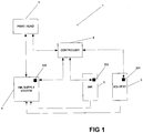
Figure 1 is a schematic illustration of a continuous ink jet printer in accordance with an embodiment of the invention; -
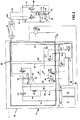
Figure 2 is a schematic representation of the continuous ink jet printer ofFigure 1 ; -
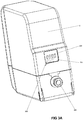
Figure 3A is a perspective view of an ink cartridge used by the printer ofFigures 1 and2 ; -
Figure 3B is a perspective view of an ink cartridge receiving portion, and a solvent cartridge receiving portion in which a solvent cartridge has been inserted, provided by the printer ofFigures 1 and2 ; -
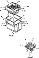
Figure 4A is an exploded perspective view from above of part of the ink supply system ofFigure 2 ; -
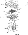
Figures 4B is a further exploded perspective view of part of the ink supply system of the printer ofFigure 2 ; -
Figure 4C is a perspective view from below of the ink supply system ofFigures 2 ,4A and4B in a partially assembled condition; -
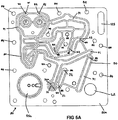
Figure 5A is a plan view of an upper surface of a feed plate of the ink supply system ofFigures 4A and4B ; -
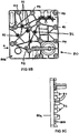
Figure 5B is a plan view of a lower surface of the feed plate ofFigure 5A , with components removed for clarity; -
Figure 5C is a side view of the feed plate in the direction of arrow A ofFigure 5B ; -
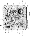
Figure 6A is a plan view of a lower surface of a manifold plate of the ink supply system ofFigures 4A and4B ; -
Figure 6B is a plan view of an upper surface of the manifold plate ofFigure 6A when fitted with components; -
Figure 6C is a side view of the manifold plate in the direction of arrow A ofFigure 6B , with components removed for clarity, the feed plate being shown in dotted line and an ink level sensor guard being shown in section; -
Figure 7A is a partially sectioned side view of part of the ink supply system ofFigures 2 ,4A and4B ; -
Figure 7B is an enlarged view of the encircled part labelled X inFigure 7A ;Figures 8A and 8B are end views of part of a filter module of the ink supply system; -
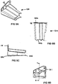
Figures 9A to 9D are respective perspective, side, side sectioned (along line B-B ofFigure 9D ) and underneath plan views of the guard ofFigure 6C ; -
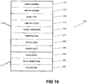
Figure 10 is a schematic illustration of data stored on an electronic data storage device associated with the ink cartridge ofFigure 3A ; -
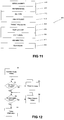
Figure 11 is a schematic illustration of data stored in an electronic data storage device associated with the ink supply system ofFigure 4A ; -
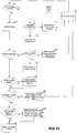
Figure 12 is a flowchart showing printer initialisation operations carried out by the controller ofFigure 1 ; -
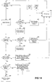
Figure 13 is a flowchart showing operations carried out by the controller ofFigure 1 to check parameters associated with an ink cartridge; -
Figure 14 is a flowchart showing operations carried out by the controller ofFigure 1 to check parameters associated with a solvent cartridge; -
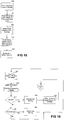
Figure 15 is a flowchart showing operations carried out by the controller ofFigure 1 to determine initial volumes of fluid in an ink cartridge and a solvent cartridge; -
Figure 16 is a flowchart showing operations carried out by the controller ofFigure 1 to update data indicating the volume of ink within an ink cartridge; and -
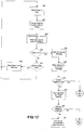
Figure 17 is a flowchart of a process used by the controller ofFigure 1 to update data indicating a volume of solvent within a solvent cartridge. -
Figure 1 schematically illustrates aninkjet printer 1, arranged to receive anink cartridge 2 and asolvent cartridge 3. Ink from theink cartridge 2 and solvent from thesolvent cartridge 3 are mixed so as to generate printing ink of a desired viscosity which is suitable for use in printing. Ink is supplied from theink cartridge 2 to anink supply system 4, and solvent is provided from thesolvent cartridge 3 to theink supply system 4. The ink supply system is arranged to mix received ink and solvent so as to produce printing ink which is provided to aprint head 5. Theprint head 5 generates a stream of ink droplets from the printing ink and each droplet of the stream of ink droplets is either directed to a substrate so as to cause print to be deposited on the substrate, or is recycled by being returned from theprint head 5 to theink supply system 4. As solvent tends to evaporate during the recycling process, it is usual to require further solvent to be added from thesolvent cartridge 3 so as to provide printing ink of the desired viscosity. - The
ink jet printer 1 is controlled by acontroller 6, which provides appropriate control signals to theink supply system 4 and theprint head 5. - The
ink cartridge 2 is provided with an electronicdata storage device 201 storing data relating to contained ink as described in further detail below. Similarly, thesolvent cartridge 3 is provided with an electronicdata storage device 301 storing data relating to contained solvent as described in further detail below. Theink supply system 4 is also provided with an electronicdata storage device 401 storing data relating to ink used within the ink supply system. Thecontroller 6 is arranged to communicate with the electronicdata storage devices - When the
ink supply system 4 is first used, data from the electronicdata storage device 201 and or the electronicdata storage device 301 is used to program the electronicdata storage device 401 so as to indicate a type of ink being used. Subsequently, when a new ink cartridge or solvent cartridge is used within the printer, a check is made by thecontroller 6 of data stored on the electronicdata storage device 401 and data stored on respective electronicdata storage devices ink cartridge 2 and thesolvent cartridge 3 to ensure compatibility. In this way, when the ink supply system is used with a particular type of ink, thecontroller 6 ensures that the printer is operable (i.e. ensures that ink is allowed to flow from theink cartridge 2 and/or the solvent cartridge 3) only if data associated with theink cartridge 2 and/orsolvent cartridge 3 as stored on the electronicdata storage devices - The
ink jet printer 1, and particularly theink supply system 4 is now described in further detail. - Referring now to
Figure 2 of the drawings, ink is delivered under pressure from theink supply system 4 to theprint head 5 and back via flexible tubes which are bundled together with other fluid tubes and electrical wires (not shown) into what is referred to in the art as an "umbilical"conduit 12. Theink supply system 4 is located in acabinet 13 which is typically table mounted and theprint head 5 is disposed outside of the cabinet. In operation, ink is drawn from a reservoir ofink 14 in amixer tank 15 by asystem pump 16, thetank 15 being topped up as necessary with ink and make-up solvent from the replaceable ink andsolvent cartridges ink cartridge 2 to themixer tank 15 as required and solvent is drawn from thesolvent cartridge 3 by suction pressure as will be described. Theink cartridge 2 takes a form illustrated inFigure 3A . It can be seen that anozzle 202 is provided through which ink flows from theink cartridge 2. The electronicdata storage device 201 comprises a plurality ofcontacts 203 which make contact with corresponding contacts provided by theprinter 1. Theink cartridge 2 comprises a relatively hard outer casing which encases a relatively flexible inner vessel. Ink is contained within the inner vessel. Theelectronic storage device 201 is mounted on a circuit board placed between the relatively hard outer casing and relatively flexible inner vessel and is visible through awindow 204 provided by theink cartridge 2. -
Figure 3B shows an inkcartridge receiving portion 205 in to which theink cartridge 2 can be placed. It can be seen that the inkcartridge receiving portion 205 comprises correspondingcontacts 206 arranged to contact with thecontacts 203 of the electronicdata storage device 201. Similarly, aneedle 207 is arranged to enter thenozzle 202 of theink cartridge 2 to allow ink to flow from theink cartridge 2 into theprinter 1. -
Figure 3B also shows thesolvent cartridge 3. It can be seen that thesolvent cartridge 3 is received in a solventcartridge receiving portion 305 having the same general form as the inkcartridge receiving portion 205. - It will be understood from the description that follows that the
ink supply system 4 and theprint head 5 include a number of flow control valves which are of the same general type: a dual coil solenoid-operated two-way, two port flow control valve. The operation of each of the valves is governed by thecontroller 6 that also controls operation of the pumps. For example, ink is transferred from theink cartridge 2 to thetank 15 through avalve 2b. Similarly, solvent is transferred from thesolvent cartridge 3 to thetank 15 through avalve 3b. Thevalves tank 15. - Referring back to
Figure 2 , ink drawn from thetank 15 is filtered first by acoarse filter 20 upstream of thesystem pump 16 and then by a relatively fine main ink filter 21 downstream of thepump 16 before it is delivered to anink feed line 22 to theprint head 5. Afluid damper 23 of conventional configuration and disposed upstream of the main filter 21 removes pressure pulsations caused by the operation of thesystem pump 16. - At the
print head 5 the ink from thefeed line 22 is supplied to a drop generator 24 via a firstflow control valve 25. The drop generator 24 comprises anozzle 26 from which the pressurised ink is discharged and a piezoelectric oscillator 27 which creates pressure perturbations in the ink flow at a predetermined frequency and amplitude so as break up the ink stream intodrops 28 of a regular size and spacing. The break up point is downstream of thenozzle 26 and coincides with acharge electrode 29 where a predetermined charge is applied to eachdrop 28. This charge determines the degree of deflection of thedrop 28 as it passes a pair ofdeflection plates 30 between which a substantially constant electric field is maintained. Uncharged drops pass substantially undeflected to agutter 31 from where they are recycled to theink supply system 4 viareturn line 32. Charged drops are projected towards asubstrate 33 that moves past theprint head 5. The position at which each drop 28 impinges on thesubstrate 33 is determined by the amount of deflection of the drop and the speed of movement of the substrate. For example, if the substrate moves in a horizontal direction, the deflection of the drop determines its vertical position in the stroke of the character matrix. - In order to ensure effective operation of the drop generator 24 the temperature of the ink entering the
print head 5 is maintained at a desired level by a heater 34 before it passes to thefirst control valve 25. In instances where the printer is started up from rest it is desirable to allow ink to bleed through thenozzle 26 without being projected toward thegutter 31 orsubstrate 33. The passage of the ink into thereturn line 32, whether it is the bleed flow or recycled unused ink captured by thegutter 31, is controlled by a secondflow control valve 35. The returning ink is drawn back to themixer tank 15 by ajet pump arrangement 36 and a thirdflow control valve 37 in theink supply system 4. - As ink flows through the system and comes into contact with air in the
tank 15 and at theprint head 5, a portion of its solvent content tends to evaporate. Theink supply system 4 is therefore also designed to supply make-up solvent as required so as to maintain the viscosity of the ink within a predefined range suitable for use. Such solvent, provided from thecartridge 3, is also used to flush theprint head 5 at appropriate times in order to keep it clear of blockages. The flush solvent is drawn through theink supply system 4 by aflush pump valve 40 that is driven by a flow of ink in abranch conduit 41 under the control of a fourthflow control valve 42 as will be described below. The flush solvent is pumped out via a filter 43 through a flush line 44 (represented in dotted line inFigure 2 ) that extends from theink supply system 4 through theumbilical conduit 12 to the firstflow control valve 25 in theprint head 5. After passing through thenozzle 26 and into thegutter 31 the solvent is drawn into thereturn line 32 via thesecond control valve 35 and to thethird control valve 37. The returning solvent flows under suction pressure from thejet pump arrangement 36. - The
jet pump arrangement 36 comprises a pair of parallel venturi pumps 50, 51 that are supplied by pressurised ink from abranch line 53 from the outlet of the main filter 21. The pumps are of known configuration and make use of the Bernoulli Principle whereby fluid flowing through a restriction in a conduit increases to a high velocity jet at the restriction and creates a low pressure area. If a side port is provided at the restriction this low pressure can be used to draw in and entrain a second fluid in a conduit connected to the side port. In this instance, the pressurised ink flows through a pair ofconduits mixer tank 15, eachconduit side port side port lines flow control valve 37 is open. Theflow control valve 37 is operated such that the flow of returning ink/solvent to eachventuri pump temperature sensor 60 in thebranch line 53. If the ink has a relatively low temperature it will have a relatively high viscosity and therefore greater pumping power is required to draw ink back from thegutter 31 in which case both pumps 50, 51 should be operated. In the event that the ink has a relatively high temperature it will have a relatively low viscosity in which case the only onepump 50 is required to generate sufficient suction. Indeed operation of both the pumps should be avoided in the latter circumstance, as there would be a risk of air getting into the supply system, which serves to cause excess evaporation of the solvent, and therefore increased consumption of make-up solvent. - The
branch line 53 is connected to line 41 that conveys ink to theflush pump valve 40 via the fourthflow control valve 42. When thecontrol valve 42 is appropriately operated by thecontroller 6 in order to effect flushing of theprint head 5 it allows theflush pump valve 40 to be pressurised by the ink fromline 41. Thevalve 40 is rolling diaphragm type in which a resilient "top-hat"diaphragm 61 divides a valve housing 62 into first and secondvariable volume chambers 63, 64. Ink is supplied under pressure to thefirst chamber 63 and make up solvent is delivered from thesolvent cartridge 3 through asolvent supply line 65 to the second chamber 64 via apressure transducer 66 and anon-return valve 67. The higher pressure of the ink entering thefirst chamber 63 relative to the solvent serves to deflect thediaphragm 61 from its normal position as shown inFigure 2 , to a position where the volume of thefirst chamber 63 has increased at the expense of the volume of the second chamber 64 and solvent is forced out of the second chamber 64 and towards theprint head 5 via theflush line 44. It is to be appreciated that other flush pump designs may be used to achieve the same operation. - In use, the atmosphere above the
mixer tank 15 soon becomes saturated with solvent and this is drawn into acondenser unit 70 where it is condensed and allowed to drain back into asolvent return line 71 via afifth control valve 72 of the ink supply system. - The
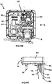
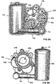
ink supply system 4, represented in circuit form inFigure 2 , is physically embodied as a modular unit that is illustrated inFigures 4A to 4C . Themixer tank 15 comprises a reservoir with a base wall 75,upstanding sidewalls 76 and an open top that defines amouth 77. Theside walls 76 terminate at their upper edge in aperipheral flange 78 around themouth 77 and provide support for amanifold block 79, which provides fluid flow conduits between components of the ink supply system, many of which are conveniently supported on theblock 79. - The
manifold block 79 comprises two vertically stacked, interconnected parts: a tank-side feed plate 80 that supports a number of components over the ink in thetank 15 and anupper manifold plate 81 on which further components are supported. Theplates Figures 5A to 5C and6A to 6C , are generally square in outline, with the tank-side feed plate 80 being slightly smaller such that it fits inside themouth 77 when theperipheral edge 82 of themanifold plate 81 rests on theflange 78 around thetank mouth 77. Aseal 83 is provided between theflange 78 and theedge 82 of themanifold plate 81. Each of theplates lower surface lower surface 81b of the manifold plate overlies, and is in interfacing abutment with theupper surface 80a of thefeed plate 80. - The
plates apertures 84 for fixing screws (not shown) that are used to connect the plates together. Themanifold plate 81 additionally has a plurality ofapertures 86 spaced about its periphery for location over upstanding pegs 87 on theflange 78 of thetank 15, and a plurality of ports 88 for connection to components of theink supply system 4. The flow of ink between the ports 88, and therefore the components of the ink supply system, is provided by a plurality of discrete channels A to K defined in thelower surface 81b of themanifold plate 81. The channels A-K interconnect the ports 88 in a predetermined relationship as can be seen inFigures 5A and6A . When the interfacing surfaces 80a, 81b of theplates upper surface 80a of thefeed plate 80 and sealed by a sealingmember 89 that is received in a pattern ofrecesses 90 defined in thatsurface 80a. The sealingmember 89 is made from a moulded elastomeric material such as synthetic rubber of the kind used in O-ring seals and is compressed in the recesses when theplates plates member 89 demarcates selectedareas 91 of theupper surface 80a that generally correspond to the pattern of channels A-K defined on themanifold plate 81, theseareas 91 serving to close the channels A-K whilst the sealingmember 89 seals the channels A-K against leakage. Some of theareas 91 bounded by the sealingmember 89 contain the ports 88 that allow fluid communication between the channels A-K and the components mounted on thefeed plate 80. A plurality ofspigots 92 extend substantially perpendicularly from the ports 88 on the lower surface80b feed plate 80 and provide for easy connection of the components to said ports 88. - The upper surface 81a of the
manifold plate 81 hasupstanding side walls 93 spaced inwardly of theperipheral apertures 86, the area inside thewalls 93 being configured to support components of theink supply system 4. - The arrangement of the channels A-K in the
manifold plate 81 is shown clearly inFigure 6A , with the sealing recesses 90 andchannel closure areas 91 being shown on thefeed plate 80 inFigure 5A . The relationship of the channels A-K to the flow lines and conduits of theink system 4 ofFigure 2 is summarised below. - Channel A defines the
branch line 53 and connectedline 41 for pressurised ink that extend from the outlet of the main filter 21, which is connected to port A5 on thefeed plate 80, to thejet pump 36 inlet that is connected to port A1.Line 41 is connected to the fourth control valve 42 (which controls activation of the flush pump) via port A4. Thepressure transducer 61 is in fluid communication with the conduit via port A3 and atemperature sensor 60 via port A2. - Channel B interconnects the second
venturi jet pump 51 and thethird control valve 37 which allows the flow to pump 51 be switch on and off. Port B1 in themanifold plate 81 is connected to thevalve 37 and port B2 in thefeed plate 80 connects to theventuri pump 51. - Channel C defines part of the
ink return line 32 from theprint head 11 and interconnects the return line (port C2) in theumbilical conduit 12 from theprint head 11 to the third control valve 37 (port C3). Port C1 is not used. - Channel D defines the conduit that carries the flow of ink returning from the
first chamber 63 of the flush pump 40 (via the fourth control valve 42) to thefirst venturi pump 50 of thejet pump arrangement 36 and/or the recovered solvent from thecondenser unit 70. Port D1 on thefeed plate 80 connects to port of thefirst venturi pump 50, port D2 on themanifold plate 81 to an outlet of thethird control valve 37, port D3 to thefourth control valve 42 and port D4 to the fifth control valve 72 (controlling the flow of recovered solvent from the condenser unit 70). - Channel E defines the
conduit 41 that delivers pressurised ink to theflush pump valve 40 and interconnects an outlet of the fourth control valve 42 (port E1 in the manifold plate) to the inlet (port E2 in the manifold plate) of thefirst chamber 63 of theflush pump valve 40. - Channel F defines part of the
solvent return line 71 from thecondenser unit 70 and interconnects the condenser drain (port F1 in the manifold plate 81) to the fifth control valve 72 (at port F2 in the manifold plate 81). - Channel G defines part of the solvent
flush line 44 and interconnects that to the flush line tube in theumbilical conduit 12 to the print head 5 (port G1 on the manifold plate 81) and an outlet of the solvent flush filter 43 (port G2 on the feed plate 80). - Channel H defines part of the
ink feed line 22 and interconnects the outlet of the damper 23 (port H2 in the feed plate 80) and ink feed line tube in theumbilical conduit 12. - Channel I defines the
solvent supply line 65 from the solvent cartridge 18 and interconnects the end of a conduit from the cartridge 18 (that end being connected toport 14 in the manifold plate 81) to the fifth control valve 72 (port I1 in the manifold plate 81). It also provides fluid communication with the non-return valve 67 (port 12 in the feed plate 81) and the pressure transducer 66 (port 13). - Channel J defines the solvent flow conduit between the
non-return valve 67 and theflush pump 40. Port J1 in thefeed plate 80 provides fluid communication between the inlet to the second chamber 64 of theflush pump 40 and port J2, also in thefeed plate 80, with an outlet of thenon-return valve 67. - Channel K defines part of the main
ink feed line 22 and extends between the outlet of the system pump 16 (port K2 on the manifold plate 81) and the inlet of the main filter 21 (port K1 on the feed plate 80). - Ports L1 on the
manifold plate 81 and L2 on thefeed plate 80 simply allow a direct connection between the outlet of thecoarse filter 20 and the inlet of the system pump 16 without any intermediate flow channel. - Each of the interfacing surfaces 80a, 81b of the
plates cylindrical recess chamber 95 for housing theflush pump 40, as best seen inFigures 7A and 7B . Similarly, thenon-return valve 67 sits in asmall chamber 96 defined betweenrecesses 96a, 96b. - Referring back to
Figures 4A and4B , the modular nature of theink supply system 4 will now be more clearly appreciated. Themanifold block 79 configuration allows the various ink supply system components to be plugged simply into fluid communication with the ports 88 (or the spigots extending from the ports) and therefore the fluid flow channels in a modular fashion. - Some of the ink supply system components supported on the
manifold block 79 will now be described with reference toFigures 4 to 9 . An integrated filter anddamper module 100 is connected to the lower surface 80b of thefeed plate 80 by fivespigots 92 as shown inFigures 4B and4C . Two of the spigots are for mounting purposes only whereas theother spigots 92 extend rearwardly from ports K1, G2 and H2 in the plate. The module, shown separately inFigures 8A and 8B comprises a pair ofcylindrical housings support 105 for the damper 23 (not shown inFigures 8A and 8B but shown inFigures 4B ,4C and7A ). Afirst housing 103 contains the main ink filter 21 and thesecond housing 104 houses the solvent filter 43. Each of thecylindrical housings respective spigot 92 in a friction fit, the opening for the main ink filter 21 connecting to the spigot at port K1 and the opening for the solvent filter 43 connecting to the spigot at port J2. A suitable sealing ring may be provided between eachspigot 92 andinlet opening 106. The filtered ink egresses from thehousing 103 ataperture 102, passes through the mountingsupport 105 to an inlet of thedamper 23 and exits the damper andsupport 105 ataperture 23a to an integrally formedoutlet conduit 107 that extends substantially parallel to the axis of thecylindrical housing spigot 92 at port H2. Afurther conduit 108 extends from a side opening in theink filter housing 103 and connects to thespigot 92 at port A5 from where the ink flows into thebranch line 53 defined by channel A. The filtered solvent passes through a side aperture in the housing into aconduit 109 that connects to thespigot 92 at port G2 from where it flows into theflush line 44 defined by channel G. - It will be seen that the
inlets 106 and theoutlet conduits respective spigots 92. - The filter and
damper module 100 also comprises the coarse filter 21 in a furthercylindrical housing 110 whose inlet has a take up pipe 111 for connection to a tube 111 that extends into theink 14 at the bottom of themixer tank 15. In operation, the system pump 16 (upstream of the coarse filter 21) operates to draw ink from thetank 15 through the take up pipe 111 and into the coarse filter 21. The outlet of the coarse filter 21 directs filtered ink along an integral right-angled outlet conduit 112 that connects to port L1 in the manifold plate from where ink flows to an inlet pipe 113 (Figures 6C and7A ) of thesystem pump 16, which extends through ports L2 and L1 and into the end of thefilter outlet conduit 112. - Several components of the
ink supply system 4 are mounted on the upper surface 81a of themanifold plate 81, these include in particular thejet pump assembly 36,system pump 16, the third to fifthflow control valves temperature sensor 60,pressure transducer 61, and a circuit board 115 for terminating electrical wiring connecting the valves, pumps and transducers to the control system. Many of these components are hidden from view inFigure 6B by the circuit board 115. - The three
flow lines umbilical conduit 12 as described above and these connect to the respect ports HI, C2, G1 that are conveniently grouped together at a connection block 116 (Figure 6B ) defined on the upper surface 81a of themanifold plate 81. The tubes are supported in cut-out notches 117 (Figure 4B ) in theside wall 93. - An ink
level sensor device 120 shown inFigures 4B ,4C , and6C is provided on themanifold block 79 in order to detect the level of ink in the mixer tank at any given time. It comprises four electricallyconductive pins lower surface 81b of themanifold plate 81. They extend through aslot 125 in thefeed plate 80 and into thetank 15 where they are designed to dip into theink 14. The first andsecond pins manifold plate 81. Thesensor 120 is designed to sense the presence of the electrically conductive ink when it completes an electrical circuit between thefirst pin 121 and one or more of theother pins second pins controller 6, which can then take a decision on whether more ink should be delivered into thetank 15. It is to be appreciated that other forms of ink level sensing devices may be used to the same effect. - In operation, ink and solvent returning into the tank from the
return line 32 may cause turbulence, particularly at the surface of theink 14, such that foam of bubbles is formed on the surface of the ink owing to surfactants present in the ink. It is known to use a deflector plate at the outlet of the return line to reduce the turbulence caused by the returning ink/solvent but this does not always eliminate foam entirely. The presence of the foam can mask the real level of ink in the tank and lead to erroneous readings by thelevel sensor 120. In order to counteract interference with the correct operation of thelevel sensor 120, aguard 130 is connected to the lower surface 80b of thefeed plate 80 and depends downwards into thetank 15 such that it shields the pins 120-124 from any surface foam generated by incoming ink or solvent. This is illustrated inFigure 6C . Theguard 130, shown in detail inFigures 9A-D , comprises a continuous thin wall made from, for example, a porous polypropylene material that has anupper end 130a with an integral laterally extendingflange 131 for connecting to thefeed plate 80 and a lower end 132 that, in use, is proximate to the base wall 75 of thetank 15. The wall tapers inwardly between its upper andlower end guard 130 may be used with any form of level sensor that depends upon immersion within the ink in thetank 15 and that the wall may be manufactured from any suitable material, porous or otherwise. - The configuration of the manifold block and in particular the channels defined at the interface between the manifold plate and the feed plate obviates the need for many pipe, tubes, hoses or the like that interconnect the components of the ink supply system. The arrangement is thus much simpler to assemble thus reducing the time associated with building the system and the likelihood of errors occurring. In general, the area inside the cabinet is much tidier such that it is easier to access individual components. The manifold block also eliminates connectors associated with such pipes, which are potential sources of leaks. The reliability of the system is therefore improved thus reducing servicing requirements.
- The general structure of the manifold block provides for a compact arrangement.
- The general arrangement of the
ink supply system 4 allows theink supply system 4 to act as an easily exchangeable component of theprinter 1. The electronicdata storage device 401 allows data relating to theink supply system 4 to be stored and read by theprinter 1. - It has been explained above that the
ink cartridge 2 has an associated electronicdata storage device 201 storing data related to ink in theink cartridge 2. The nature of this data is now described with reference toFigure 10 . - The stored data comprises read only
data 210 andsequential write data 211. The read only data comprises serial number data uniquely identifying theelectronic storage device 201 which is suitably stored in Read Only Memory (ROM).Ink reference data 213 comprises 6 bytes of ASCII code representing 5 alpha-numeric characters which provide a reference for the ink contained within theink cartridge 2.Fluid type data 215 comprises two bytes of data indicating a fluid type value. A Fluid Type value indicates a type of solvent that an ink is based upon. For example, the solvent base of an ink may be MEK, Ethanol or water. The fluid type which is used is determined by factors such as the substrate to be printed on and other factors such as environmental considerations. Within each solvent family there are several different inks which are formulated to meet other application requirements. These could include the colour of the ink, how the dried ink adheres to a particular material, etc.. Each of these inks has uniqueink reference data 213. - The read only
data 210 further comprises various data indicating parameters of the ink contained within theink cartridge 2. Specifically, the read onlydata 210 comprises time offlight data 214 indicating a time of flight for ink contained within theink cartridge 2 andtarget pressure data 216 indicating the correct pressure at which the printer should be operated for ink within theink cartridge 2.Temperature data 217 indicates a temperature to which the ink should be heated for use. -
Batch code data 218 is allocated during production of thecartridge 2 and indicates a batch in which theink cartridge 2 was produced.Expiry date data 219 indicates a date by which theink cartridge 2 should be used. - The electronic
data storage device 201 also stores data which can be updated by theprinter 1, in the form of thesequential write data 211. Specifically,fluid level data 220 indicates the current level of fluid within thecartridge 2,insertion data 221 indicates the number of times which the cartridge has been inserted into a printer, and runhours data 222 indicates a number of hours for which the ink cartridge has been used. - The electronic
data storage device 201 can take any suitable form. In a preferred embodiment of the invention the electronic data storage device is a Maxim-DS2431 1024 bit 1-wire EEPROM, although other suitable devices can be used. - The
sequential write data 211 is processed as follows. Each of thefluid level data 220, theinsertion data 221 and therun hours data 222 is allocated a respective area of memory on the EEPROM in which all bits are initiated to a common state. Considering thefluid level data 220 as an example, as ink is removed from theink cartridge 2, and this is determined by theprinter 1 in the manner described below, bits of the allocated memory are changed to the other state. That is, thefluid level data 220 may initially comprise 1 byte of data in which all bits are set to a state of "1". When it is determined that one eighth of the ink within the cartridge has been used, one bit is set to a state of "0". When it is determined that one quarter of the ink within thecartridge 2 has been used, a further bit is set to a state of "0". In this way, thefluid level data 220 can be read by the printer and depending upon the number of bits which have been set to a state of "0" the quantity of ink within the cartridge can be determined. - The
insertions data 221 and therun hours data 222 can also be suitably implemented in the manner described above with reference to thefluid level data 220. Theinsertion data 221 and therun hours data 222 can be used by thecontroller 6 to ensure that theink cartridge 2 is not used more than a predetermined number of times or for more than a predetermined period, so as to minimise the risk of component failure. - The electronic
data storage device 301 associated with thesolvent cartridge 3 stores data which is generally similar to that described with reference toFigure 10 . It should however be noted that in a preferred embodiment of the invention fluid type data is not stored on the electronicdata storage device 301, the solvent type instead being provided by solvent reference data corresponding to theink reference data 213. -
Figure 11 shows data stored on the electronicdata storage device 401 associated with theink supply system 4. It can be seen thatserial number data 410 is stored (suitably in ROM) providing an identifier for theink supply system 4. Various data indicative of an ink within theink supply system 4 is also stored. As mentioned above, data indicating a type of ink is written to the electronicdata storage device 401 when theink supply system 4 is first used so as to associate theink supply system 4 with a particular type of ink and in this way to prevent an ink supply system which has been used with one type of ink from later being used with an incompatible ink.Ink reference data 411 indicates a reference number for an ink used in theink supply system 4.Ink type data 412 indicates an ink type. Various data indicating parameters of ink within the ink supply system is also stored. Specifically, time offlight data 413,target pressure data 414 andtemperature data 415 are all stored on theelectronic storage device 401 and respectively correspond to the time offlight data 215,target pressure data 216, andtemperature data 217 described with reference to the electronicdata storage device 201 inFigure 10 . -
Fluid level data 416 indicates a level of fluid within thereservoir 14 of theink tank 15 of theink supply system 4. Thisfluid level data 416 is derived from the output of the inklevel sensor device 120 described above with reference toFigures 4B ,4C and6C .Machine type data 417 indicates a type of printer in which theink supply system 4 is intended to be used. Runhours data 418 indicates the number of hours for which theink supply system 4 has been used. Theserial number 410 andmachine type data 417 are preferably implemented as read only data. That is, theprinter 1 is preferably inhibited from amending this data. Data relating to the type of ink used by theink supply system 4, that is theink reference data 411 andink type data 412 is preferably implemented as write once data. That is, while theprinter 1 should be able to update this data when theink supply system 4 is used for the first time based upon the insertedink cartridge 2 it should not be possible for this data to be subsequently changed during operation. - The
fluid level data 416 is writable by theprinter 1 so as to be updated as the level of thereservoir 14 in theink tank 15 varies. - The
run hours data 418 is preferably implemented as sequential write data as described above with reference to thefluid level data 222 ofFigure 10 . - It was indicated with reference to
Figure 11 thatmachine type data 417 indicated a type of printer with which theink supply system 4 was intended for use. In a preferred embodiment of the invention, theprinter 1 has an associated electronic storage device storing various data relevant to the printer. This data can be used to determine whether themachine type data 417 of thedata storage device 401 indicates that the ink supply system is suitable for use in a particular printer. That is, where differing printer types are provided, differing ink supply systems can also be provided, and data stored on thedata storage device 401 can be used to determine whether a particular ink supply system is compatible with a particular printer. - It has been explained above that the controller 6 (
Figure 1 ) is arranged to ensure that anink supply system 4 is only provided with ink and solvent from compatible cartridges. Operations carried out by theprinter 1 when anink cartridge 2 and asolvent cartridge 3 are fitted to theprinter 1 are now described with reference to the flowcharts ofFigures 12 to 17 . - Referring first to
Figure 12 , at step S1 printer operation is initialised by a user. As described above, ink from theink cartridge 2 flows to theink supply system 4 through thevalve 2b, and at step S2 a check is made to determine whether thevalve 2b is closed. If thevalve 2b is not closed, action is taken to close thevalve 2b at step S3, and processing returns to step S2. If the valve is closed, processing passes from step S2 to step S4. Solvent from thesolvent cartridge 3 passes to theink supply system 4 though thevalve 3b. A further check is carried out at step S4 to determine whether thevalve 3b is closed. If this is not the case, processing passes from step S4 to step S5 where thevalve 3b is closed, before processing returns to step S4. If the check of step S4 is satisfied, processing passes from step S4 to step S6 where various printer initialisation operations are carried out. - It can be seen from
Figure 12 that when printer operation begins, it is ensured that both theink valve 2b and thesolvent valve 3b are closed. This is to ensure that various checks are carried out (as described below) before any ink is transferred from theink cartridge 2 to theink supply system 4 and before any solvent is transferred from thesolvent cartridge 3 to theink supply system 4. - Referring now to
Figure 13 , checks carried out in relation to theink cartridge 2 are described. At step S7 a check is carried out to determine whether an ink cartridge is inserted into the ink cartridge receiving portion 205 (Figure 3B ). If no ink cartridge is inserted, processing passes from step S7 to step S8 where a check is made to determine whether the check of step S7 has been carried out more than twice. If the check of step S8 is satisfied, processing passes to step S9, where a message is displayed on a user interface of the printer instructing the user to contact a service engineer. If however the check of step S8 determines that the check of step S7 has not been carried out more than twice, processing passes to step S10 where the user is presented with a message on the user interface of the printer indicating the absence of an ink cartridge. Processing passes from step S10 to step S11 where an ink cartridge is inserted into the inkcartridge receiving portion 205 by the user, at which time processing passes from step S11 back to step S7. - If the check of step S7 (arranged to determine whether an ink cartridge is present) is satisfied, processing passes from step S7 to step S12 where any error indication provided at step S10 is reset, before processing passes to step S13. At step S13 and subsequent steps data is read from the electronic
data storage device 201 associated with theink cartridge 2. At step S13ink reference data 213 andfluid type data 215 indicating a type of ink held in theink cartridge 2 is read from the electronicdata storage device 201. A check is carried out to determine whether the type of ink held in the cartridge matches data indicating a type of ink which has previously been used in the ink supply system 4 (that data having been read from the electronic data storage device 401). If it is determined that theink cartridge 2 contains a different type of ink from that previously used in theink supply system 4, processing passes from step S13 to step S14. Here a counter indicating a number of times that incorrect ink has been detected is checked. If it is determined that there have been more than two previous checks which indicated that theink cartridge 2 contained incorrect ink, processing passes to step S15 where the user interface displays a message indicating that the user should contact a service engineer. If however the counter indicates that there have not been more than two previous checks indicating that theink cartridge 2 contained incorrect ink, processing passes from step S14 to step S16 where the user is informed that the ink cartridge contains incorrect ink. A user then inserts a further ink cartridge at step S11, before processing continues at step S7. - If it is determined at step S13 that the ink contained within the
ink cartridge 2 and that used in theink supply system 4 match, processing passes from step S13 to step S17, where a check is carried out to determine whether various ink parameters stored within the printer match those stored in the electronicdata storage device 201. Such parameters can include time offlight data 215,temperature data 217 andpressure data 216 as shown inFigure 10 . If it is determined at step S17 that one or more ink parameters stored within the printer differ from those stored in the electronicdata storage device 201, processing passes to step S18 where parameters stored within the printer are updated, before processing continues at step S19. If it is determined at step S17 that the parameters stored within the printer match data stored in the electronicdata storage device 201, processing passes directly from step S17 to step S19. In this way variations in ink parameters can be properly handled by theprinter 1. - At step S19, a check is made to compare a current date stored in the printer with expiry date data 219 (
Figure 10 ) stored in the electronicdata storage device 201. If it is determined that theexpiry date data 219 indicates that the ink cartridge can no longer be used, processing passes to step S20 where an appropriate message is displayed by means of the user interface, before a further cartridge is inserted at step S11. - If the check of step S19 indicates that the expiry date has not yet passed, processing passes from step S19 to step S21 where a check is carried out to determine whether the expiry date is within one month of a current date stored by the printer. If this is the case, an appropriate message is displayed at step S22 to advise the user to order further ink supplies, before processing continues at step S23 where any error indications are cleared from the user interface. If the check of step S21 indicates that the expiry date is not within one month of the current date stored by the printer, processing passes directly from step S21 to step S23.
-
Figure 14 shows operations carried out in relation to thesolvent cartridge 3. The operations ofFigure 14 are essentially equivalent to those carried out in relation to theink cartridge 2 as described with reference toFigure 13 , and the operations ofFigure 14 are therefore only briefly described. - At step S24 a check is carried out to determine whether the
solvent cartridge 3 is inserted into the solventcartridge receiving portion 305. If this check is not satisfied processing passes to step S25 where a check is carried out to determine a number of times which the check of step S24 has been performed. If the check of step S24 has been carried out more than twice, processing passes to step S26 where the user is advised to contact a service engineer. Otherwise, processing passes from step S25 to step S27 where the user is asked to insert a solvent cartridge. A solvent cartridge is inserted at step S28, and processing returns to step S24. - When the check of step S24 determines that a solvent cartridge is present, any warning message is reset at step S29. At step S30 a check is made to compare data stored in the electronic
data storage device 301 and indicating the type of solvent contained in thesolvent cartridge 3 with data indicating the expected solvent type, given the type of ink used within theink supply system 4. If the incorrect solvent is contained in thesolvent cartridge 3 processing passes from step S30 to step S31 where a check is carried out to determine whether the check of step S30 has been carried out too many times. If this is the case, a message is displayed on the user interface advising the user to contact a service engineer at step S32. Otherwise, processing passes from step S31 to step S33 where a message is displayed indicating that incorrect solvent is contained in thesolvent cartridge 3, before a further solvent cartridge is inserted at step S28. - If the check of step S30 is satisfied, processing passes from step S30 to step S34 where a check is made to determine whether the solvent expiry date (as indicated by expiry date data stored in the electronic data storage device 301) has passed. If the expiry date has passed, processing passes from step S34 to step S35 where the user is advised to fit a further solvent cartridge to the printer. A further solvent cartridge is inserted at step S28.
- If the expiry date has not passed, processing passes from step S34 to step S36 where a check is carried out to determine whether the solvent is within one month of its expiry date. If this is the case, an appropriate message is displayed at step S37 before processing continues at step S38 where any residual error indications are cleared. If the solvent is not within one month of its expiry date, processing passes directly from step S36 to step S38.
- It has been explained above that the electronic
data storage device 201 associated with theink cartridge 2 stores data indicating a quantity of ink within theink cartridge 2. Similarly, the electronicdata storage device 301 associated with thesolvent cartridge 3 stores data indicating a quantity of solvent within thesolvent cartridge 3. Processing of this data is now described with reference toFigures 15, 16 and17 , the described processing being carried out after that shown inFigures 12 ,13 and14 . - Referring to
Figure 15 , at step S40 data indicating the quantity of ink within theink cartridge 2 is read by theprinter 1 from the electronicdata storage device 201. At step S41 the read data is stored by theprinter 1 and also displayed to a user by means of a user interface. At step S42 theprinter 1 reads data from the electronicdata storage device 301 indicating a quantity of solvent contained in thesolvent cartridge 3, and this data is stored by theprinter 1 and displayed to a user at step S43. Atstep S44 valves respective cartridges ink supply system 4. It should be noted that thevalves Figures 13 and14 are satisfied. In this way, the valves ensure that ink and solvent can be added to theink supply system 4 only if checks relating to the ink and solvent are satisfied. - Updating of data indicating a quantity of ink within the
ink cartridge 2 is now described with reference toFigure 16 . At step S45 an algorithm is operated which counts of number of droplets of ink which are projected from theprinthead 5 onto a substrate. Given knowledge of the quantity of ink included in each droplet, the quantity of ink used can be determined, and this determined quantity is used to determine a modified quantity of ink within theink cartridge 2, based on an assumption that ink removed from thereservoir 14 and used in printing is replenished with an equal quantity of ink from theink cartridge 2. This modified quantity is used to update data stored in the electronicdata storage device 201 and to provide appropriate data to the user by means of the user interface at step S46. - At step S47 a check is carried out to determine whether the algorithm of step S45 has determined that the
ink cartridge 2 is empty. If this is the case, processing passes to step S48 where an appropriate message is displayed to the user via a user interface. Processing then continues at step S49 where data stored in the electronicdata storage device 201 is appropriately updated. Processing passes from step S49 to step S9 ofFigure 13 . - If the check of step S47 determines that the
ink cartridge 2 is not empty, processing passes to step S50 where a check is carried out to determine whether there is a low level of ink within theink cartridge 2. If this is the case, processing passes to step S51 where an appropriate message is displayed on the user interface of theprinter 1. It can be seen that processing passes from each of steps S50 and S51 to step S45 so as to provide constant monitoring of the level of ink contained within theink cartridge 2. - Referring to
Figure 17 , processing is described to monitor the quantity of solvent within thesolvent cartridge 3. At step S52 theprinter 1 reads a negative pressure within thesolvent cartridge 3, and at step S53 the negative pressure is converted to a quantity of solvent within thesolvent cartridge 3. In general terms, the negative pressure increases as quantity of solvent decreases. At step S54 the user interface is updated to indicate the determined quantity of solvent, and appropriate data is provided to theelectronic storage device 301. At step S55 a check is carried out to determine whether thesolvent cartridge 3 is empty. If this is the case, processing passes to step S56 where an appropriate message is displayed by means of the user interface. At step S57 appropriate data is provided to the electronicdata storage device 301. - Processing passes from step S57 to step S58 where a check is carried out to determine whether the solvent cartridge has been replaced within one hour of display of the message at step S56, if this is the case processing as described with reference to
Figure 14 is carried out beginning at step S28. If the check of step S58 determines that the solvent cartridge has not been replaced, a warning message is displayed at step S59 indicating that the printer will shut down if the solvent cartridge is not replaced. At step S60 a check is carried out to determine whether the solvent cartridge has been replaced within thirty minutes of display of the message at step S59, if this is the case, processing as described with reference toFigure 14 beginning at step S28 is carried out, otherwise, processing passes from step S60 to step S61 where the printer is shutdown. - If the check of step S55 determines that the
solvent cartridge 3 is not empty, processing passes from step S55 to step S62 where a check is carried out to determine whether the quantity of solvent in thesolvent cartridge 3 is below a predetermined level. If this is the case, an appropriate message is presented at step S63. It can be seen that processing returns from each of steps S62 and S63 to step S52, allowing constant monitoring of the quantity of solvent stored within thesolvent cartridge 3. - It has been described above that the quantity of solvent contained within the
solvent cartridge 3 is determined based upon negative pressure measurements, while the quantity of ink stored within theink cartridge 2 is determined based upon a number of droplets of ink output from the printhead. In some embodiments, the quantity of ink is within theink cartridge 2 is also determined based upon negative pressure measurements. - It will be appreciated that the volume of ink within the
ink cartridge 2 and the solvent within thesolvent cartridge 3 can be determined in any convenient way, and this determination can be used to update both an indication provided to a user on a user interface and data stored on the electronicdata storage devices ink cartridge 2 andsolvent cartridge 3 on respective electronicdata storage devices ink cartridge 2 and thesolvent cartridge 3 are provided with data accurately indicating a quantity of ink currently contained in the cartridge. - The described and illustrated embodiments are to be considered as illustrative and not restrictive in character, it being understood that only the preferred embodiments have been shown and described and that all changes and modifications that come within the scope of the inventions as defined in the claims are desired to be protected. It should be understood that while the use of words such as "preferable", "preferably", "preferred" or "more preferred" in the description suggest that a feature so described may be desirable, it may nevertheless not be necessary and embodiments lacking such a feature may be contemplated as within the scope of the invention as defined in the appended claims. In relation to the claims, it is intended that when words such as "a," "an," "at least one," or "at least one portion" are used to preface a feature there is no intention to limit the claim to only one such feature unless specifically stated to the contrary in the claim. When the language "at least a portion" and/or "a portion" is used the item can include a portion and/or the entire item unless specifically stated to the contrary. Reference to a controller is to be understood as a reference to any system or systems arranged to provide the necessary control. For example, control may be provided by one or more suitably programmed microprocessors or alternatively by one or more bespoke hardware devices.
Claims (14)
- A continuous ink jet printer (1) comprising:a printing fluid cartridge receiving portion (205, 305) arranged to receive a printing fluid cartridge (2,3) and to allow passage of printing fluid from a received printing fluid cartridge to printing fluid conduits of the ink jet printer;a data reader (206) arranged to read data indicating a quantity of fluid within a received cartridge from an electronic data storage device (201) associated with the received printing fluid cartridge (2, 3); anda controller (6) arranged to determine a quantity of fluid within said printing fluid cartridge (2, 3) based upon a pressure within said printing fluid cartridge and to generate (S53) update data usable to modify data stored on said electronic data storage device (201) based upon said determination and to modify (S54) data stored on said electronic storage device based upon said update data such that data stored on said electronic data storage device (201) indicates an updated quantity of fluid in said printing fluid cartridge (2, 3).
- A continuous ink jet printer according to claim 1, wherein the printing fluid is ink or solvent.
- A continuous ink jet printer according to any preceding claim, further comprising the printing fluid cartridge (2, 3) wherein an electronic data storage device (201) associated with the printing fluid cartridge stores first data indicating a quantity of fluid initially stored in said printing fluid cartridge, and second data indicating a quantity of fluid removed from the printing fluid cartridge.
- A continuous ink jet printer according to claim 3, wherein said update data is arranged to modify said second data.
- A continuous ink jet printer according to claim 3, wherein the controller is arranged to generate said update data based on a current quantity of fluid in said printing fluid cartridge and a difference between said initial quantity of fluid and said current quantity of fluid.
- A continuous inkjet printer according to claims 3, 4 or 5, wherein said second data comprises a predetermined number of data elements having first and second states, each data element being associated with a predetermined quantity of ink, and said quantity of ink removed from the ink cartridge is represented by a number of data elements set to the first state.
- A continuous inkjet printer according to any preceding claim, wherein
said printing fluid cartridge receiving portion is a plurality of printing fluid cartridge receiving portions (205, 305) each arranged to receive a respective printing fluid cartridge (2, 3) and to allow passage of printing fluid from a received printing fluid cartridge to printing fluid conduits of the ink jet printer (1);
said data reader (206) is a plurality of data readers each arranged to read data indicating a quantity of fluid within a received cartridge from a respective electronic data storage device (201) associated with a respective received printing fluid cartridge (2,3); and
said controller is arranged to generate update data usable to modify data stored on each of said electronic data storage devices (201), and to modify data stored on each electronic storage device based upon said update data, such that data stored on each electronic data storage device indicates an updated quantity of fluid in a respective printing fluid cartridge (2,3). - An electronic data storage device for use with an ink cartridge (2) of a continuous inkjet printer, the electronic storage device (201) being configured to hold:ink reference data (213) providing a reference for the ink contained within the ink cartridge,fluid type data (215) indicating the type of solvent that the ink contained within the ink cartridge is based upon; anddata indicating a quantity of ink within the ink cartridge, the electronic storage device being arranged to receive update data from a continuous ink jet printer and to store data on said electronic data storage device based upon said update data such that said electronic data storage device indicates an updated quantity of ink in said ink cartridge (2).
- An ink cartridge (2) for a continuous ink jet printer, the ink cartridge comprising:a vessel arranged to hold ink; andan electronic data storage device (201) according to claim 8 wherein the data indicating a quantity of ink indicates a quantity of ink in said vessel.
- An ink cartridge according to claim 9, wherein said electronic data storage device (201) stores first data indicating a quantity of ink initially stored in said ink cartridge, and second data indicating a quantity of ink removed from the ink cartridge.
- An ink cartridge according to claim 10, wherein said update data is arranged to modify said second data.
- An ink cartridge according to claim 10 or 11, wherein said second data comprises a predetermined number of data elements having first and second states, each data element being associated with a predetermined quantity of ink, and said quantity of ink removed from the ink cartridge is represented by a number of data elements set to the first state.
- An ink cartridge according to claim 12, comprising a plurality of electrical contacts (203) arranged to make contact with corresponding electrical contacts of an ink jet printer.
- An ink cartridge according to claim 13, wherein said electronic data storage device (201) is mounted on a circuit board providing electrical connections between said electrical contacts and said electronic data storage device.
Priority Applications (2)
| Application Number | Priority Date | Filing Date | Title |
|---|---|---|---|
| EP19218361.4A EP3698974A1 (en) | 2007-10-12 | 2008-10-09 | Ink jet printer |
| PL08806561T PL2195170T3 (en) | 2007-10-12 | 2008-10-09 | Ink jet printer |
Applications Claiming Priority (2)
| Application Number | Priority Date | Filing Date | Title |
|---|---|---|---|
| GBGB0720289.8A GB0720289D0 (en) | 2007-10-12 | 2007-10-12 | Ink jet printer |
| PCT/GB2008/003424 WO2009047511A1 (en) | 2007-10-12 | 2008-10-09 | Ink jet printer |
Related Child Applications (1)
| Application Number | Title | Priority Date | Filing Date |
|---|---|---|---|
| EP19218361.4A Division EP3698974A1 (en) | 2007-10-12 | 2008-10-09 | Ink jet printer |
Publications (2)
| Publication Number | Publication Date |
|---|---|
| EP2195170A1 EP2195170A1 (en) | 2010-06-16 |
| EP2195170B1 true EP2195170B1 (en) | 2020-01-01 |
Family
ID=38813969
Family Applications (2)
| Application Number | Title | Priority Date | Filing Date |
|---|---|---|---|
| EP19218361.4A Pending EP3698974A1 (en) | 2007-10-12 | 2008-10-09 | Ink jet printer |
| EP08806561.0A Active EP2195170B1 (en) | 2007-10-12 | 2008-10-09 | Ink jet printer |
Family Applications Before (1)
| Application Number | Title | Priority Date | Filing Date |
|---|---|---|---|
| EP19218361.4A Pending EP3698974A1 (en) | 2007-10-12 | 2008-10-09 | Ink jet printer |
Country Status (9)
| Country | Link |
|---|---|
| US (1) | US8449054B2 (en) |
| EP (2) | EP3698974A1 (en) |
| KR (1) | KR20100061579A (en) |
| CN (1) | CN101977774B (en) |
| ES (1) | ES2777880T3 (en) |
| GB (1) | GB0720289D0 (en) |
| HU (1) | HUE048756T2 (en) |
| PL (1) | PL2195170T3 (en) |
| WO (1) | WO2009047511A1 (en) |
Families Citing this family (12)
| Publication number | Priority date | Publication date | Assignee | Title |
|---|---|---|---|---|
| JP4529775B2 (en) * | 2005-04-15 | 2010-08-25 | ソニー株式会社 | Reproduction device, display method and display program thereof, display device and display method, and recording / reproduction device and display method thereof |
| GB0720289D0 (en) | 2007-10-12 | 2007-11-28 | Videojet Technologies Inc | Ink jet printer |
| WO2015181924A1 (en) * | 2014-05-29 | 2015-12-03 | キヤノン株式会社 | Coating device, imprint device, and method for manufacturing goods |
| JP6768523B2 (en) | 2014-06-05 | 2020-10-14 | ヴィデオジェット テクノロジーズ インコーポレイテッド | Filter Modules and Continuous Inkjet Printers for Continuous Inkjet Printers |
| CN106457831B (en) | 2014-06-05 | 2019-04-19 | 录象射流技术公司 | The continuous inkjet print head of embedded charging electrode with zero adjustment |
| US9770906B2 (en) | 2014-06-05 | 2017-09-26 | Videojet Technologies Inc. | Ink buildup sensor arrangement |
| JP6929615B2 (en) * | 2016-03-31 | 2021-09-01 | キヤノン株式会社 | Management systems, monitoring devices, their methods, and programs |
| US10831941B2 (en) * | 2017-10-04 | 2020-11-10 | Aditazz, Inc. | Method and system for automating resource selection and building plan layout generation |
| WO2020117196A1 (en) * | 2018-12-03 | 2020-06-11 | Hewlett-Packard Development Company, L.P. | Logic circuitry |
| GB201919228D0 (en) * | 2019-12-23 | 2020-02-05 | Videojet Technologies Inc | Method of operating a printhead |
| GB202020025D0 (en) | 2020-12-17 | 2021-02-03 | Videojet Technologies Inc | Apparatus and method for printing |
| CN112706522B (en) * | 2020-12-25 | 2022-04-08 | 镭德杰标识科技武汉有限公司 | Print head, umbilical cord pipe and printing assembly |
Citations (21)
| Publication number | Priority date | Publication date | Assignee | Title |
|---|---|---|---|---|
| US4639738A (en) | 1985-04-12 | 1987-01-27 | Eastman Kodak Company | Ink level detection system for ink jet printing apparatus |
| US5283613A (en) | 1993-02-19 | 1994-02-01 | Xerox Corporation | Monitoring system with dual memory for electrophotographic printing machines using replaceable cartridges |
| US5315317A (en) | 1989-06-29 | 1994-05-24 | Canon Kabushiki Kaisha | Ink quantity detecting device and recording apparatus with the devie |
| US5506611A (en) | 1989-08-05 | 1996-04-09 | Canon Kabushiki Kaisha | Replaceable ink cartridge having surface wiring resistance pattern |
| US5610635A (en) | 1994-08-09 | 1997-03-11 | Encad, Inc. | Printer ink cartridge with memory storage capacity |
| WO1997028001A1 (en) | 1996-02-01 | 1997-08-07 | Imaje S.A. | Industrial printer for use with at least one cartridge of consumable material |
| JPH09314861A (en) | 1996-06-04 | 1997-12-09 | Canon Inc | Ink jet recording device and ink jet unit |
| US5788388A (en) | 1997-01-21 | 1998-08-04 | Hewlett-Packard Company | Ink jet cartridge with ink level detection |
| EP0887595A2 (en) | 1997-06-26 | 1998-12-30 | Fir-Com di Zullo Giovanni | Automatic venting device for evacuated-tube steam heating systems |
| US5860363A (en) | 1997-01-21 | 1999-01-19 | Hewlett-Packard Company | Ink jet cartridge with separately replaceable ink reservoir |
| US20020012016A1 (en) | 1998-09-01 | 2002-01-31 | Wilson Rhonda L. | Pressure based ink level detector and method |
| US6360174B1 (en) | 1998-05-08 | 2002-03-19 | Funai Electric Co., Ltd. | Apparatus for detecting quantity level of residual ink in ink cartridge |
| US6454381B1 (en) | 2001-04-27 | 2002-09-24 | Hewlett-Packard Company | Method and apparatus for providing ink container extraction characteristics to a printing system |
| US6565198B2 (en) | 1998-11-02 | 2003-05-20 | Seiko Epson Corporation | Ink cartridge and printer using the same |
| US20030206220A1 (en) | 1995-04-27 | 2003-11-06 | Childers Winthrop D. | Ink container refurbishment system |
| US6648434B2 (en) | 2001-03-08 | 2003-11-18 | Hewlett-Packard Development Company, L.P. | Digitally compensated pressure ink level sense system and method |
| EP1568504A2 (en) | 2000-11-27 | 2005-08-31 | Océ-Technologies B.V. | Method of preparing ink containers filled with ink |
| US6938976B2 (en) | 1999-06-16 | 2005-09-06 | Eastman Kodak Company | Printer and method therefor adapted to sense data uniquely associated with a consumable loaded into the printer |
| US20060127153A1 (en) * | 2002-11-12 | 2006-06-15 | Guy Menchik | Three-dimensional object printing |
| US7270407B2 (en) | 2001-06-29 | 2007-09-18 | Hewlett-Packard Development Company, L.P. | Methods for digitally printing on ceramics |
| WO2009047511A1 (en) | 2007-10-12 | 2009-04-16 | Videojet Technologies Inc. | Ink jet printer |
Family Cites Families (23)
| Publication number | Priority date | Publication date | Assignee | Title |
|---|---|---|---|---|
| US4555712A (en) * | 1984-08-03 | 1985-11-26 | Videojet Systems International, Inc. | Ink drop velocity control system |
| JPS62222852A (en) * | 1986-03-26 | 1987-09-30 | Hitachi Ltd | Apparatus for detecting residual amount solvent of ink jet recording apparatus |
| EP0646470B1 (en) * | 1993-09-08 | 1999-12-15 | Hitachi, Ltd. | An ink jet printing apparatus |
| US5532720A (en) * | 1993-09-15 | 1996-07-02 | Quad/Tech, Inc. | Solvent recovery system for ink jet printer |
| US6065824A (en) | 1994-12-22 | 2000-05-23 | Hewlett-Packard Company | Method and apparatus for storing information on a replaceable ink container |
| US6130695A (en) * | 1995-04-27 | 2000-10-10 | Hewlett-Packard Company | Ink delivery system adapter |
| US6585359B1 (en) | 1997-06-04 | 2003-07-01 | Hewlett-Packard Development Company, L.P. | Ink container providing pressurized ink with ink level sensor |
| US6010210A (en) | 1997-06-04 | 2000-01-04 | Hewlett-Packard Company | Ink container having a multiple function chassis |
| DE19812480A1 (en) | 1998-03-21 | 1999-09-23 | E B S Gmbh | Ink-jet printer for labeling goods |
| DE69926688T2 (en) | 1998-05-13 | 2006-02-23 | Seiko Epson Corp. | Ink cartridge for an inkjet printer |
| JP2000218818A (en) * | 1998-11-26 | 2000-08-08 | Seiko Epson Corp | Ink container and printer using the same |
| JP4395943B2 (en) | 1998-11-26 | 2010-01-13 | セイコーエプソン株式会社 | Printing apparatus and information management method thereof |
| JP2000270129A (en) | 1999-03-12 | 2000-09-29 | Ryuji Ito | Image printer provided with ink-jet type printer |
| US6799820B1 (en) | 1999-05-20 | 2004-10-05 | Seiko Epson Corporation | Liquid container having a liquid detecting device |
| EP1080912A3 (en) | 1999-08-31 | 2001-09-05 | Seiko Epson Corporation | Ink cartridge management system, printer, and ink cartridge |
| JP2001096869A (en) | 1999-10-04 | 2001-04-10 | Seiko Epson Corp | Recording device, semiconductor device and recording head device |
| ES2261373T3 (en) | 2000-01-18 | 2006-11-16 | Seiko Epson Corporation | INK CARTRIDGE, INJECTION INJECTION RECORD DEVICE USING THIS CARTRIDGE AND A METHOD TO CONTROL THE CLEANING OF THE REGISTER HEAD OF THE RECORDING DEVICE. |
| WO2001053104A1 (en) | 2000-01-21 | 2001-07-26 | Seiko Epson Corporation | Ink cartridge for recording device and ink jet recording device |
| US7077512B2 (en) | 2000-12-26 | 2006-07-18 | Seiko Epson Corporation | Ink jet type recording apparatus, ink type information setting method in the apparatus and ink cartridge used in the apparatus |
| US6789876B2 (en) | 2001-03-21 | 2004-09-14 | Aaron G. Barclay | Co-operating mechanical subassemblies for a scanning carriage, digital wide-format color inkjet print engine |
| JP4143319B2 (en) | 2002-03-29 | 2008-09-03 | キヤノン株式会社 | Recording apparatus and ink consumption management method |
| US6830323B2 (en) | 2002-08-13 | 2004-12-14 | Eastman Kodak Company | Restricting flash spread when welding housing halves of cartridge together |
| JP4630551B2 (en) | 2003-02-14 | 2011-02-09 | 理想科学工業株式会社 | Ink container |
-
2007
- 2007-10-12 GB GBGB0720289.8A patent/GB0720289D0/en not_active Ceased
-
2008
- 2008-10-09 US US12/680,974 patent/US8449054B2/en active Active
- 2008-10-09 EP EP19218361.4A patent/EP3698974A1/en active Pending
- 2008-10-09 EP EP08806561.0A patent/EP2195170B1/en active Active
- 2008-10-09 WO PCT/GB2008/003424 patent/WO2009047511A1/en active Application Filing
- 2008-10-09 HU HUE08806561A patent/HUE048756T2/en unknown
- 2008-10-09 CN CN200880120514.3A patent/CN101977774B/en active Active
- 2008-10-09 KR KR1020107010333A patent/KR20100061579A/en not_active Application Discontinuation
- 2008-10-09 ES ES08806561T patent/ES2777880T3/en active Active
- 2008-10-09 PL PL08806561T patent/PL2195170T3/en unknown
Patent Citations (23)
| Publication number | Priority date | Publication date | Assignee | Title |
|---|---|---|---|---|
| US4639738A (en) | 1985-04-12 | 1987-01-27 | Eastman Kodak Company | Ink level detection system for ink jet printing apparatus |
| US5315317A (en) | 1989-06-29 | 1994-05-24 | Canon Kabushiki Kaisha | Ink quantity detecting device and recording apparatus with the devie |
| US5506611A (en) | 1989-08-05 | 1996-04-09 | Canon Kabushiki Kaisha | Replaceable ink cartridge having surface wiring resistance pattern |
| US5283613A (en) | 1993-02-19 | 1994-02-01 | Xerox Corporation | Monitoring system with dual memory for electrophotographic printing machines using replaceable cartridges |
| US5610635A (en) | 1994-08-09 | 1997-03-11 | Encad, Inc. | Printer ink cartridge with memory storage capacity |
| US20030206220A1 (en) | 1995-04-27 | 2003-11-06 | Childers Winthrop D. | Ink container refurbishment system |
| WO1997028001A1 (en) | 1996-02-01 | 1997-08-07 | Imaje S.A. | Industrial printer for use with at least one cartridge of consumable material |
| AU712509B2 (en) | 1996-02-01 | 1999-11-11 | Markem-Imaje Holding | Industrial printer suited to receive at least one consumable cartridge |
| JPH09314861A (en) | 1996-06-04 | 1997-12-09 | Canon Inc | Ink jet recording device and ink jet unit |
| US5860363A (en) | 1997-01-21 | 1999-01-19 | Hewlett-Packard Company | Ink jet cartridge with separately replaceable ink reservoir |
| US5788388A (en) | 1997-01-21 | 1998-08-04 | Hewlett-Packard Company | Ink jet cartridge with ink level detection |
| EP0887595A2 (en) | 1997-06-26 | 1998-12-30 | Fir-Com di Zullo Giovanni | Automatic venting device for evacuated-tube steam heating systems |
| US6360174B1 (en) | 1998-05-08 | 2002-03-19 | Funai Electric Co., Ltd. | Apparatus for detecting quantity level of residual ink in ink cartridge |
| US20020012016A1 (en) | 1998-09-01 | 2002-01-31 | Wilson Rhonda L. | Pressure based ink level detector and method |
| US6565198B2 (en) | 1998-11-02 | 2003-05-20 | Seiko Epson Corporation | Ink cartridge and printer using the same |
| US6938976B2 (en) | 1999-06-16 | 2005-09-06 | Eastman Kodak Company | Printer and method therefor adapted to sense data uniquely associated with a consumable loaded into the printer |
| EP1568504A2 (en) | 2000-11-27 | 2005-08-31 | Océ-Technologies B.V. | Method of preparing ink containers filled with ink |
| US6648434B2 (en) | 2001-03-08 | 2003-11-18 | Hewlett-Packard Development Company, L.P. | Digitally compensated pressure ink level sense system and method |
| US6454381B1 (en) | 2001-04-27 | 2002-09-24 | Hewlett-Packard Company | Method and apparatus for providing ink container extraction characteristics to a printing system |
| US7270407B2 (en) | 2001-06-29 | 2007-09-18 | Hewlett-Packard Development Company, L.P. | Methods for digitally printing on ceramics |
| US20060127153A1 (en) * | 2002-11-12 | 2006-06-15 | Guy Menchik | Three-dimensional object printing |
| WO2009047511A1 (en) | 2007-10-12 | 2009-04-16 | Videojet Technologies Inc. | Ink jet printer |
| EP2195170A1 (en) | 2007-10-12 | 2010-06-16 | Videojet Technologies Inc. | Ink jet printer |
Non-Patent Citations (6)
| Title |
|---|
| ANONYMOUS: "Fiche de données de sécurité, SH-5175E-A", IMAJE SA, 10 June 2002 (2002-06-10), pages 1 - 6, XP055768723 |
| ANONYMOUS: "Fiche de données de sécurité, SH-9550", IMAJE SA, 11 April 2006 (2006-04-11), pages 1 - 7, XP055768720 |
| ANONYMOUS: "Material safety data sheet , I-270BK printing ink", DOMINO, 19 January 2004 (2004-01-19), pages 1 - 7, XP055768715 |
| ANONYMOUS: "Material safety data sheet, InkSource, Ink 16-81", VIDEOJET, 18 May 2005 (2005-05-18), pages 1 - 5, XP055768716 |
| R.H. LEACH ET AL: "The Printing Ink Manual. 5th ed.", 1993, SPRINGER, article "Chapter 12: Ink-Jet and Chapter 17: Health, safety and the environment", pages: 678 - 956, XP055768712 |
| STEPHEN F.POND: "Inkjet technology and Product Development Strategies", 2000, TORREY PINES, article "Ink Design", pages: iii - v1, 153-164, 177-1480, 206-209, XP055768699 |
Also Published As
| Publication number | Publication date |
|---|---|
| GB0720289D0 (en) | 2007-11-28 |
| CN101977774B (en) | 2014-05-28 |
| PL2195170T3 (en) | 2020-10-19 |
| WO2009047511A1 (en) | 2009-04-16 |
| KR20100061579A (en) | 2010-06-07 |
| CN101977774A (en) | 2011-02-16 |
| US8449054B2 (en) | 2013-05-28 |
| HUE048756T2 (en) | 2020-08-28 |
| US20100238206A1 (en) | 2010-09-23 |
| EP3698974A1 (en) | 2020-08-26 |
| ES2777880T3 (en) | 2020-08-06 |
| EP2195170A1 (en) | 2010-06-16 |
Similar Documents
| Publication | Publication Date | Title |
|---|---|---|
| EP2195170B1 (en) | Ink jet printer | |
| US20100220128A1 (en) | Ink jet printer | |
| EP2200830B1 (en) | Ink jet module | |
| EP2217447B1 (en) | Ink jet printing | |
| EP2200834B1 (en) | Filter for ink supply system | |
| EP2200831B1 (en) | Ink supply system | |
| EP3307542B1 (en) | Module for ink jet printer | |
| CN109414935B (en) | Printing | |
| KR19980070630A (en) | Replaceable ink cartridges for ink jet printing systems and their service methods | |
| EP2217446B1 (en) | Ink jet printer | |
| EP2200832B1 (en) | Flush pump for ink supply system |
Legal Events
| Date | Code | Title | Description |
|---|---|---|---|
| PUAI | Public reference made under article 153(3) epc to a published international application that has entered the european phase |
Free format text: ORIGINAL CODE: 0009012 |
|
| 17P | Request for examination filed |
Effective date: 20100331 |
|
| AK | Designated contracting states |
Kind code of ref document: A1 Designated state(s): AT BE BG CH CY CZ DE DK EE ES FI FR GB GR HR HU IE IS IT LI LT LU LV MC MT NL NO PL PT RO SE SI SK TR |
|
| AX | Request for extension of the european patent |
Extension state: AL BA MK RS |
|
| DAX | Request for extension of the european patent (deleted) | ||
| 17Q | First examination report despatched |
Effective date: 20120531 |
|
| GRAP | Despatch of communication of intention to grant a patent |
Free format text: ORIGINAL CODE: EPIDOSNIGR1 |
|
| STAA | Information on the status of an ep patent application or granted ep patent |
Free format text: STATUS: GRANT OF PATENT IS INTENDED |
|
| INTG | Intention to grant announced |
Effective date: 20170208 |
|
| GRAJ | Information related to disapproval of communication of intention to grant by the applicant or resumption of examination proceedings by the epo deleted |
Free format text: ORIGINAL CODE: EPIDOSDIGR1 |
|
| STAA | Information on the status of an ep patent application or granted ep patent |
Free format text: STATUS: EXAMINATION IS IN PROGRESS |
|
| INTC | Intention to grant announced (deleted) | ||
| GRAP | Despatch of communication of intention to grant a patent |
Free format text: ORIGINAL CODE: EPIDOSNIGR1 |
|
| STAA | Information on the status of an ep patent application or granted ep patent |
Free format text: STATUS: GRANT OF PATENT IS INTENDED |
|
| INTG | Intention to grant announced |
Effective date: 20191008 |
|
| GRAS | Grant fee paid |
Free format text: ORIGINAL CODE: EPIDOSNIGR3 |
|
| GRAJ | Information related to disapproval of communication of intention to grant by the applicant or resumption of examination proceedings by the epo deleted |
Free format text: ORIGINAL CODE: EPIDOSDIGR1 |
|
| GRAL | Information related to payment of fee for publishing/printing deleted |
Free format text: ORIGINAL CODE: EPIDOSDIGR3 |
|
| STAA | Information on the status of an ep patent application or granted ep patent |
Free format text: STATUS: EXAMINATION IS IN PROGRESS |
|
| GRAR | Information related to intention to grant a patent recorded |
Free format text: ORIGINAL CODE: EPIDOSNIGR71 |
|
| STAA | Information on the status of an ep patent application or granted ep patent |
Free format text: STATUS: GRANT OF PATENT IS INTENDED |
|
| GRAA | (expected) grant |
Free format text: ORIGINAL CODE: 0009210 |
|
| STAA | Information on the status of an ep patent application or granted ep patent |
Free format text: STATUS: THE PATENT HAS BEEN GRANTED |
|
| TPAC | Observations filed by third parties |
Free format text: ORIGINAL CODE: EPIDOSNTIPA |
|
| INTG | Intention to grant announced |
Effective date: 20191120 |
|
| AK | Designated contracting states |
Kind code of ref document: B1 Designated state(s): AT BE BG CH CY CZ DE DK EE ES FI FR GB GR HR HU IE IS IT LI LT LU LV MC MT NL NO PL PT RO SE SI SK TR |
|
| REG | Reference to a national code |
Ref country code: GB Ref legal event code: FG4D |
|
| REG | Reference to a national code |
Ref country code: CH Ref legal event code: EP Ref country code: AT Ref legal event code: REF Ref document number: 1219292 Country of ref document: AT Kind code of ref document: T Effective date: 20200115 |
|
| REG | Reference to a national code |
Ref country code: IE Ref legal event code: FG4D |
|
| REG | Reference to a national code |
Ref country code: DE Ref legal event code: R096 Ref document number: 602008061940 Country of ref document: DE |
|
| REG | Reference to a national code |
Ref country code: RO Ref legal event code: EPE |
|
| REG | Reference to a national code |
Ref country code: NL Ref legal event code: MP Effective date: 20200101 |
|
| REG | Reference to a national code |
Ref country code: LT Ref legal event code: MG4D |
|
| PG25 | Lapsed in a contracting state [announced via postgrant information from national office to epo] |
Ref country code: NL Free format text: LAPSE BECAUSE OF FAILURE TO SUBMIT A TRANSLATION OF THE DESCRIPTION OR TO PAY THE FEE WITHIN THE PRESCRIBED TIME-LIMIT Effective date: 20200101 Ref country code: LT Free format text: LAPSE BECAUSE OF FAILURE TO SUBMIT A TRANSLATION OF THE DESCRIPTION OR TO PAY THE FEE WITHIN THE PRESCRIBED TIME-LIMIT Effective date: 20200101 Ref country code: PT Free format text: LAPSE BECAUSE OF FAILURE TO SUBMIT A TRANSLATION OF THE DESCRIPTION OR TO PAY THE FEE WITHIN THE PRESCRIBED TIME-LIMIT Effective date: 20200527 Ref country code: CZ Free format text: LAPSE BECAUSE OF FAILURE TO SUBMIT A TRANSLATION OF THE DESCRIPTION OR TO PAY THE FEE WITHIN THE PRESCRIBED TIME-LIMIT Effective date: 20200101 Ref country code: FI Free format text: LAPSE BECAUSE OF FAILURE TO SUBMIT A TRANSLATION OF THE DESCRIPTION OR TO PAY THE FEE WITHIN THE PRESCRIBED TIME-LIMIT Effective date: 20200101 Ref country code: NO Free format text: LAPSE BECAUSE OF FAILURE TO SUBMIT A TRANSLATION OF THE DESCRIPTION OR TO PAY THE FEE WITHIN THE PRESCRIBED TIME-LIMIT Effective date: 20200401 |
|
| REG | Reference to a national code |
Ref country code: ES Ref legal event code: FG2A Ref document number: 2777880 Country of ref document: ES Kind code of ref document: T3 Effective date: 20200806 |
|
| REG | Reference to a national code |
Ref country code: HU Ref legal event code: AG4A Ref document number: E048756 Country of ref document: HU |
|
| PG25 | Lapsed in a contracting state [announced via postgrant information from national office to epo] |
Ref country code: BG Free format text: LAPSE BECAUSE OF FAILURE TO SUBMIT A TRANSLATION OF THE DESCRIPTION OR TO PAY THE FEE WITHIN THE PRESCRIBED TIME-LIMIT Effective date: 20200401 Ref country code: GR Free format text: LAPSE BECAUSE OF FAILURE TO SUBMIT A TRANSLATION OF THE DESCRIPTION OR TO PAY THE FEE WITHIN THE PRESCRIBED TIME-LIMIT Effective date: 20200402 Ref country code: HR Free format text: LAPSE BECAUSE OF FAILURE TO SUBMIT A TRANSLATION OF THE DESCRIPTION OR TO PAY THE FEE WITHIN THE PRESCRIBED TIME-LIMIT Effective date: 20200101 Ref country code: IS Free format text: LAPSE BECAUSE OF FAILURE TO SUBMIT A TRANSLATION OF THE DESCRIPTION OR TO PAY THE FEE WITHIN THE PRESCRIBED TIME-LIMIT Effective date: 20200501 Ref country code: LV Free format text: LAPSE BECAUSE OF FAILURE TO SUBMIT A TRANSLATION OF THE DESCRIPTION OR TO PAY THE FEE WITHIN THE PRESCRIBED TIME-LIMIT Effective date: 20200101 Ref country code: SE Free format text: LAPSE BECAUSE OF FAILURE TO SUBMIT A TRANSLATION OF THE DESCRIPTION OR TO PAY THE FEE WITHIN THE PRESCRIBED TIME-LIMIT Effective date: 20200101 |
|
| REG | Reference to a national code |
Ref country code: DE Ref legal event code: R026 Ref document number: 602008061940 Country of ref document: DE |
|
| PLBI | Opposition filed |
Free format text: ORIGINAL CODE: 0009260 |
|
| PLAX | Notice of opposition and request to file observation + time limit sent |
Free format text: ORIGINAL CODE: EPIDOSNOBS2 |
|
| PG25 | Lapsed in a contracting state [announced via postgrant information from national office to epo] |
Ref country code: SK Free format text: LAPSE BECAUSE OF FAILURE TO SUBMIT A TRANSLATION OF THE DESCRIPTION OR TO PAY THE FEE WITHIN THE PRESCRIBED TIME-LIMIT Effective date: 20200101 Ref country code: DK Free format text: LAPSE BECAUSE OF FAILURE TO SUBMIT A TRANSLATION OF THE DESCRIPTION OR TO PAY THE FEE WITHIN THE PRESCRIBED TIME-LIMIT Effective date: 20200101 Ref country code: EE Free format text: LAPSE BECAUSE OF FAILURE TO SUBMIT A TRANSLATION OF THE DESCRIPTION OR TO PAY THE FEE WITHIN THE PRESCRIBED TIME-LIMIT Effective date: 20200101 |
|
| 26 | Opposition filed |
Opponent name: DOMINO UK LIMITED Effective date: 20200930 Opponent name: DOVER EUROPE SARL Effective date: 20201001 |
|
| REG | Reference to a national code |
Ref country code: AT Ref legal event code: MK05 Ref document number: 1219292 Country of ref document: AT Kind code of ref document: T Effective date: 20200101 |
|
| PG25 | Lapsed in a contracting state [announced via postgrant information from national office to epo] |
Ref country code: AT Free format text: LAPSE BECAUSE OF FAILURE TO SUBMIT A TRANSLATION OF THE DESCRIPTION OR TO PAY THE FEE WITHIN THE PRESCRIBED TIME-LIMIT Effective date: 20200101 |
|
| PG25 | Lapsed in a contracting state [announced via postgrant information from national office to epo] |
Ref country code: SI Free format text: LAPSE BECAUSE OF FAILURE TO SUBMIT A TRANSLATION OF THE DESCRIPTION OR TO PAY THE FEE WITHIN THE PRESCRIBED TIME-LIMIT Effective date: 20200101 |
|
| PLBB | Reply of patent proprietor to notice(s) of opposition received |
Free format text: ORIGINAL CODE: EPIDOSNOBS3 |
|
| REG | Reference to a national code |
Ref country code: CH Ref legal event code: PL |
|
| PG25 | Lapsed in a contracting state [announced via postgrant information from national office to epo] |
Ref country code: LU Free format text: LAPSE BECAUSE OF NON-PAYMENT OF DUE FEES Effective date: 20201009 Ref country code: MC Free format text: LAPSE BECAUSE OF FAILURE TO SUBMIT A TRANSLATION OF THE DESCRIPTION OR TO PAY THE FEE WITHIN THE PRESCRIBED TIME-LIMIT Effective date: 20200101 |
|
| REG | Reference to a national code |
Ref country code: BE Ref legal event code: MM Effective date: 20201031 |
|
| PG25 | Lapsed in a contracting state [announced via postgrant information from national office to epo] |
Ref country code: LI Free format text: LAPSE BECAUSE OF NON-PAYMENT OF DUE FEES Effective date: 20201031 Ref country code: BE Free format text: LAPSE BECAUSE OF NON-PAYMENT OF DUE FEES Effective date: 20201031 Ref country code: CH Free format text: LAPSE BECAUSE OF NON-PAYMENT OF DUE FEES Effective date: 20201031 |
|
| PG25 | Lapsed in a contracting state [announced via postgrant information from national office to epo] |
Ref country code: MT Free format text: LAPSE BECAUSE OF FAILURE TO SUBMIT A TRANSLATION OF THE DESCRIPTION OR TO PAY THE FEE WITHIN THE PRESCRIBED TIME-LIMIT Effective date: 20200101 Ref country code: CY Free format text: LAPSE BECAUSE OF FAILURE TO SUBMIT A TRANSLATION OF THE DESCRIPTION OR TO PAY THE FEE WITHIN THE PRESCRIBED TIME-LIMIT Effective date: 20200101 |
|
| PLAB | Opposition data, opponent's data or that of the opponent's representative modified |
Free format text: ORIGINAL CODE: 0009299OPPO |
|
| R26 | Opposition filed (corrected) |
Opponent name: DOVER EUROPE SARL Effective date: 20201001 |
|
| REG | Reference to a national code |
Ref country code: CH Ref legal event code: PK Free format text: BERICHTIGUNGEN |
|
| RIC2 | Information provided on ipc code assigned after grant |
Ipc: B41J 2/185 20060101ALI20221017BHEP Ipc: B41J 2/175 20060101AFI20221017BHEP |
|
| APBM | Appeal reference recorded |
Free format text: ORIGINAL CODE: EPIDOSNREFNO |
|
| APBP | Date of receipt of notice of appeal recorded |
Free format text: ORIGINAL CODE: EPIDOSNNOA2O |
|
| APAH | Appeal reference modified |
Free format text: ORIGINAL CODE: EPIDOSCREFNO |
|
| APAW | Appeal reference deleted |
Free format text: ORIGINAL CODE: EPIDOSDREFNO |
|
| APBM | Appeal reference recorded |
Free format text: ORIGINAL CODE: EPIDOSNREFNO |
|
| APBP | Date of receipt of notice of appeal recorded |
Free format text: ORIGINAL CODE: EPIDOSNNOA2O |
|
| APBQ | Date of receipt of statement of grounds of appeal recorded |
Free format text: ORIGINAL CODE: EPIDOSNNOA3O |
|
| P01 | Opt-out of the competence of the unified patent court (upc) registered |
Effective date: 20230530 |
|
| PGFP | Annual fee paid to national office [announced via postgrant information from national office to epo] |
Ref country code: RO Payment date: 20230912 Year of fee payment: 16 Ref country code: IT Payment date: 20230913 Year of fee payment: 16 Ref country code: IE Payment date: 20230823 Year of fee payment: 16 Ref country code: GB Payment date: 20230817 Year of fee payment: 16 |
|
| PGFP | Annual fee paid to national office [announced via postgrant information from national office to epo] |
Ref country code: PL Payment date: 20230830 Year of fee payment: 16 Ref country code: FR Payment date: 20230821 Year of fee payment: 16 |
|
| PGFP | Annual fee paid to national office [announced via postgrant information from national office to epo] |
Ref country code: ES Payment date: 20231222 Year of fee payment: 16 |
|
| PGFP | Annual fee paid to national office [announced via postgrant information from national office to epo] |
Ref country code: TR Payment date: 20231006 Year of fee payment: 16 Ref country code: HU Payment date: 20230901 Year of fee payment: 16 Ref country code: DE Payment date: 20230822 Year of fee payment: 16 |