EP2194760A1 - Device with several lamps switched in series - Google Patents
Device with several lamps switched in series Download PDFInfo
- Publication number
- EP2194760A1 EP2194760A1 EP08021297A EP08021297A EP2194760A1 EP 2194760 A1 EP2194760 A1 EP 2194760A1 EP 08021297 A EP08021297 A EP 08021297A EP 08021297 A EP08021297 A EP 08021297A EP 2194760 A1 EP2194760 A1 EP 2194760A1
- Authority
- EP
- European Patent Office
- Prior art keywords
- current
- bypass
- series
- current source
- lighting means
- Prior art date
- Legal status (The legal status is an assumption and is not a legal conclusion. Google has not performed a legal analysis and makes no representation as to the accuracy of the status listed.)
- Ceased
Links
Images


Classifications
-
- H—ELECTRICITY
- H05—ELECTRIC TECHNIQUES NOT OTHERWISE PROVIDED FOR
- H05B—ELECTRIC HEATING; ELECTRIC LIGHT SOURCES NOT OTHERWISE PROVIDED FOR; CIRCUIT ARRANGEMENTS FOR ELECTRIC LIGHT SOURCES, IN GENERAL
- H05B45/00—Circuit arrangements for operating light-emitting diodes [LED]
- H05B45/40—Details of LED load circuits
- H05B45/44—Details of LED load circuits with an active control inside an LED matrix
- H05B45/48—Details of LED load circuits with an active control inside an LED matrix having LEDs organised in strings and incorporating parallel shunting devices
-
- H—ELECTRICITY
- H05—ELECTRIC TECHNIQUES NOT OTHERWISE PROVIDED FOR
- H05B—ELECTRIC HEATING; ELECTRIC LIGHT SOURCES NOT OTHERWISE PROVIDED FOR; CIRCUIT ARRANGEMENTS FOR ELECTRIC LIGHT SOURCES, IN GENERAL
- H05B45/00—Circuit arrangements for operating light-emitting diodes [LED]
- H05B45/30—Driver circuits
- H05B45/37—Converter circuits
- H05B45/3725—Switched mode power supply [SMPS]
- H05B45/38—Switched mode power supply [SMPS] using boost topology
-
- H—ELECTRICITY
- H05—ELECTRIC TECHNIQUES NOT OTHERWISE PROVIDED FOR
- H05B—ELECTRIC HEATING; ELECTRIC LIGHT SOURCES NOT OTHERWISE PROVIDED FOR; CIRCUIT ARRANGEMENTS FOR ELECTRIC LIGHT SOURCES, IN GENERAL
- H05B45/00—Circuit arrangements for operating light-emitting diodes [LED]
- H05B45/50—Circuit arrangements for operating light-emitting diodes [LED] responsive to malfunctions or undesirable behaviour of LEDs; responsive to LED life; Protective circuits
- H05B45/54—Circuit arrangements for operating light-emitting diodes [LED] responsive to malfunctions or undesirable behaviour of LEDs; responsive to LED life; Protective circuits in a series array of LEDs
Abstract
Description
Die vorliegende Erfindung betrifft eine Vorrichtung mit mehreren elektrisch in Serie geschalteten Leuchtmitteln, mindestens einem Überbrückungsstrompfad, durch den mindestens eines der Leuchtmittel elektrisch überbrückbar ist, und einer Stromquelle zur Versorgung der Leuchtmittel mit Strom.The present invention relates to a device having a plurality of lamps connected in series in series, at least one bridging current path, by means of which at least one of the lighting means can be electrically bridged, and a current source for supplying the lighting means with current.
Bei einer bekannten Vorrichtung dieser Art dienen die Überbrückungsstrompfade dazu, einzelne Leuchtmittel selektiv ein- und auszuschalten. Dabei tritt das Problem auf, dass bei einer selektiven Abschaltung einzelner Leuchtmittel eine erhöhte Spannung über den nicht überbrückten, d.h. nicht ausgeschalteten, Leuchtmitteln abfällt. Der erhöhte Spannungsabfall bewirkt einen erhöhten Stromfluss durch die nicht überbrückten Leuchtmittel und kann zu einer Beschädigung dieser Leuchtmittel führen.In a known device of this type, the bridging current paths serve to selectively turn on and off individual illuminants. In this case, the problem arises that in a selective shutdown of individual bulbs increased voltage over the unbridged, i. not switched off, bulbs drops. The increased voltage drop causes an increased current flow through the non-bridged bulbs and can lead to damage of these bulbs.
Der Erfindung liegt die Aufgabe zugrunde, eine Vorrichtung der eingangs genannten Art zu schaffen, deren zuverlässige Funktion dauerhaft sichergestellt ist.The invention has for its object to provide a device of the type mentioned, whose reliable function is permanently ensured.
Zur Lösung der Aufgabe ist eine Vorrichtung mit den Merkmalen des Anspruchs 1 vorgesehen.To solve the problem, a device having the features of claim 1 is provided.
Gemäß Anspruch 1 umfasst eine erfindungsgemäße Vorrichtung mehrere elektrisch in Serie geschaltete Leuchtmittel, mindestens einen Überbrückungsstrompfad, durch den mindestens eines der Leuchtmittel elektrisch überbrückbar ist, eine Stromquelle zur Versorgung der Leuchtmittel mit Strom und eine Strombeschränkungseinrichtung, welche im Falle einer elektrischen Überbrückung mindestens eines der Leuchtmittel einen durch die nicht überbrückten Leuchtmittel fließenden Strom beschränkt.According to claim 1, a device according to the invention comprises a plurality of lamps connected in series in series, at least one bypass current path, by the at least one of the lighting means is electrically bridged, a power source for supplying the lighting means with power and a current limiting device, which limits in the case of electrical bridging at least one of the lighting means a current flowing through the non-bridged lighting means current.
Bei der erfindungsgemäßen Vorrichtung werden die in Serie geschalteten Leuchtmittel durch eine gemeinsame Stromquelle mit Strom versorgt. Somit ist es nicht notwendig, für jedes Leuchtmittel eine eigene Stromquelle bereit zu stellen. Die Stromquelle stellt einen im Wesentlichen konstanten Strom bereit. Die Spannung der Stromquelle entspricht vorzugsweise etwa der Summe der Vorwärtsspannungen der in Serie geschalteten Leuchtmittel. Unter Vorwärtsspannung wird hierbei die Spannung verstanden, die für den normalen Leuchtbetrieb eines eingeschalteten Leuchtmittels an diesem anliegen muss.In the device according to the invention, the lamps connected in series are supplied with power by a common current source. Thus, it is not necessary to provide a separate power source for each light source. The power source provides a substantially constant current. The voltage of the current source preferably corresponds approximately to the sum of the forward voltages of the series-connected bulbs. In this case, forward voltage is understood to mean the voltage which must be applied to the normal lighting operation of a switched-on illuminant.
Durch den Überbrückungsstrompfad ist ein zugeordnetes Leuchtmittel elektrisch überbrückbar. Hierdurch lässt sich das Leuchtmittel selektiv aus- bzw. einschalten, indem das Leuchtmittel - zum Beispiel durch eine geeignete Steuerung gesteuert - elektrisch überbrückt wird bzw. eine vorhandene elektrische Überbrückung aufgehoben wird.By bridging current path an associated light source is electrically bridged. As a result, the light source can be switched off or on selectively by the light source being electrically bridged, for example controlled by a suitable control, or an existing electrical bridging is canceled out.
Konkret bewirkt die elektrische Überbrückung des Leuchtmittels, dass die über das Leuchtmittel abfallende Spannung auf einen Wert reduziert wird, der unter der Vorwärtsspannung des Leuchtmittels liegt, so dass das Leuchtmittel entweder gar nicht mehr oder nur noch mit verringerter Helligkeit leuchtet.In concrete terms, the electrical bridging of the luminous means causes the voltage drop across the luminous means to be reduced to a value which is below the forward voltage of the luminous means, so that the luminous means either no longer or only shines with reduced brightness.
Der in Folge des Überbrückens des Leuchtmittels auftretende verringerte Spannungsabfall über dieses Leuchtmittel führt dazu, dass ein entsprechend erhöhter Anteil der über die Serienschaltung von Leuchtmitteln insgesamt abfallenden Spannung über die nicht überbrückten Leuchtmittel abfällt. Unter der Annahme einer gleich bleibenden über die Serienschaltung abfallenden Gesamtspannung hätte dies einen erhöhten Stromfluss durch die nicht überbrückten Leuchtmittel und gegebenenfalls deren Beschädigung oder Ausfall zur Folge.The occurring due to the bridging of the bulb reduced voltage drop across this bulb causes a corresponding increased proportion of across the series circuit of bulbs total decreasing voltage across the non-bridged bulbs decreases. Assuming a constant overall voltage dropping across the series connection, this would result in an increased current flow through the non-bridged lamps and, if appropriate, their damage or failure.
Um einen solchen erhöhten Stromfluss durch die nicht überbrückten Leuchtmittel zu vermeiden oder zumindest zu beschränken, ist erfindungsgemäß eine Strombeschränkungseinrichtung vorgesehen, welche im Falle einer elektrischen Überbrückung mindestens eines der Leuchtmittel den durch die nicht überbrückten Leuchtmittel fließenden Strom beschränkt.In order to avoid or at least limit such an increased current flow through the non-bridged luminous means, according to the invention a current limiting device is provided which, in the case of an electrical bridging of at least one of the luminous means, limits the current flowing through the non-bridged luminous means.
Die Strombeschränkungseinrichtung kann dabei so ausgestaltet sein, dass sie im Falle einer Überbrückung eines Leuchtmittels für einen zusätzlichen Spannungsabfall sorgt. Dieser zusätzliche Spannungsabfall wirkt bevorzugt so, dass er einer Zunahme der über die nicht überbrückten Leuchtmittel abfallenden Spannung entgegenwirkt, d.h. also diese verhindert oder zumindest reduziert bzw. beschränkt.In this case, the current limiting device can be designed such that it ensures an additional voltage drop in the case of a bridging of a luminous means. This additional voltage drop is preferably such that it counteracts an increase in the voltage across the non-bridged bulbs, i. So this prevents or at least reduced or limited.
Bei einer solchen Ausgestaltung der Strombeschränkungseinrichtung wird also der im Falle einer Überbrückung eines oder mehrerer Leuchtmittel durch die nicht überbrückten Leuchtmittel fließende Strom dadurch beschränkt, dass einer Zunahme der über die nicht überbrückten Leuchtmittel abfallenden Spannung durch Erzeugen eines zusätzlichen Spannungsabfalls entgegengewirkt wird.In such an embodiment of the current-limiting device, the current flowing in the event of a bridging of one or more light sources by the non-bridged light-emitting means is thereby limited by counteracting an increase in the voltage drop across the non-bridged light-emitting means by generating an additional voltage drop.
Ein solcher zusätzlicher Spannungsabfall kann beispielsweise in Serie zu der Serienschaltung aus Leuchtmitteln, d.h. der Serienschaltung vor- oder nachgeschaltet, innerhalb der Serienschaltung, z.B. in Serie zu einem Leuchtmittel, oder innerhalb eines Überbrückungsstrompfades erzeugt werden, durch den ein Leuchtmittel überbrückt wird.Such an additional voltage drop, for example, in series with the series circuit of bulbs, ie the series circuit or pre downstream, within the series circuit, for example, in series with a light source, or be generated within a bypass current path through which a light source is bridged.
Die erfindungsgemäße Beschränkung des im Falle einer Überbrückung eines Leuchtmittels durch die nicht überbrückten Leuchtmittel fließenden Stromes verhindert, dass die nicht überbrückten Leuchtmittel durch eine übermäßige Zunahme des durch sie fließenden Stromes belastet oder beschädigt werden. Im Ergebnis ist hierdurch eine zuverlässige Funktion der erfindungsgemäßen Vorrichtung dauerhaft sichergestellt.The restriction according to the invention of the current flowing in the event of a bridging of a luminous means by the non-bridged luminous means prevents the non-bridged luminous means from being loaded or damaged by an excessive increase in the current flowing through them. As a result, this reliably ensures reliable operation of the device according to the invention.
Vorteilhafte Ausbildungen der Erfindung sind in den Unteransprüchen, der Beschreibung und den Zeichnungen beschrieben.Advantageous embodiments of the invention are described in the subclaims, the description and the drawings.
So kann die Strombeschränkungseinrichtung gemäß einer ersten Ausführungsform unabhängig von der Stromquelle sein. Diese Ausführungsform ist besonders vorteilhaft, da die Unabhängigkeit der Strombeschränkungseinrichtung von der Stromquelle größtmögliche Flexibilität hinsichtlich der Gestaltung der Gesamtvorrichtung bietet. Die Stromquelle und die Strombeschränkungseinrichtung können mit anderen Worten getrennt voneinander entworfen, optimiert, hergestellt und eingebaut werden.Thus, the current limiting device according to a first embodiment may be independent of the power source. This embodiment is particularly advantageous because the independence of the current limiting device from the power source offers the greatest possible flexibility with regard to the design of the overall device. In other words, the power source and the current limiting device can be designed, optimized, manufactured and installed separately from one another.
Gemäß einer weiteren Ausbildung der Erfindung ist jedem Leuchtmittel ein eigener Überbrückungsstrompfad zugeordnet. Auf diese Weise kann jedes Leuchtmittel einzeln überbrückt, d.h. also ein- und ausgeschaltet werden. Dies gewährleistet eine optimale Flexibilität in der Steuerung der einzelnen Leuchtmittel und ermöglicht ein breites Spektrum an Anwendungen und Leuchtmustern.According to a further embodiment of the invention, each illuminant is assigned a separate bypass current path. In this way, each light source can be bridged individually, ie switched on and off. This ensures optimal flexibility in the control of the individual lamps and allows a wide range of applications and light patterns.
Das Öffnen und Schließen eines Überbrückungsstrompfades erfolgt vorzugsweise mittels eines in dem Überbrückungsstrompfad angeordneten Schalters. Prinzipiell kommen als Schalter für die Überbrückungsstrompfade unter anderem elektrische Schalter, mechanische Schalter und elektromechanische Schalter in Frage.The opening and closing of a bypass current path is preferably effected by means of a switch arranged in the bypass current path. In principle, suitable switches for the bypass current paths include electrical switches, mechanical switches and electromechanical switches in question.
Gemäß einer weiteren Ausführungsform ist mindestens eines der Leuchtmittel eine Leuchtdiode (LED). Insbesondere können alle Leuchtmittel LEDs sein. In letzterem Fall ist es besonders bevorzugt, wenn alle LEDs vom gleichen Typ sind und/oder einen im Wesentlichen identischen Vorwärtsstrom aufweisen. Unter dem Vorwärtsstrom einer LED bzw. eines Leuchtmittels allgemein wird hier der Strom verstanden, der bei dem normalen Leuchtbetrieb eines eingeschalteten Leuchtmittels durch das Leuchtmittel fließt, mit anderen Worten also der Strom, der durch das Leuchtmittel fließt, wenn die Vorwärtsspannung gemäß voranstehender Definition an dem Leuchtmittel anliegt.According to a further embodiment, at least one of the lighting means is a light-emitting diode (LED). In particular, all lamps can be LEDs. In the latter case, it is particularly preferred if all the LEDs are of the same type and / or have a substantially identical forward current. The forward current of an LED or of a luminous means in general is understood here as meaning the current which flows through the luminous means in the normal luminous operation of a switched-on luminous means, in other words the current which flows through the luminous means when the forward voltage according to the above definition is applied to the luminous means Illuminant is applied.
LEDs eignen sich besonders gut für eine Ansteuerung mittels Pulsweitenmodulation und für ein wiederholtes Ein- und Ausschalten allgemein, da sie auch durch wiederholtes Ein- und Ausschalten allenfalls minimal verschleißen. Die Vorwärtsspannungen von LEDs liegen zudem typischerweise in einem Bereich, der es erlaubt, mehrere in Serie geschaltete LEDs durch insbesondere im Automobilbereich typischerweise verwendete Gleichspannungen, wie z.B. 12 Volt oder 24 Volt, mit Strom zu versorgen, gegebenenfalls unter Einsatz eines Stromwandlers. Sind alle LEDs vom gleichen Typ, so besitzen sie, abgesehen von geringfügigen herstellungsbedingten Abweichungen, alle den gleichen Vorwärtsstrom und können somit besonders effizient in einer Serienschaltung durch eine gemeinsame Stromquelle betrieben werden. Entsprechendes gilt für andersartige Leuchtmittel eines Typs oder auch für Leuchtmittel unterschiedlicher Arten und Typen, die einen im Wesentlichen identischen Vorwärtsstrom aufweisen.LEDs are particularly well suited for control by means of pulse width modulation and for repeated switching on and off in general, as they wear at least minimally by repeated switching on and off. In addition, the forward voltages of LEDs are typically within a range that allows multiple serially connected LEDs to be powered by DC voltages typically used in the automotive industry, such as 12 volts or 24 volts, optionally using a current transformer. If all LEDs are of the same type, they all have the same forward current, apart from minor deviations due to production, and can therefore be operated particularly efficiently in a series connection by a common current source. The same applies to different types of bulbs of a type or bulbs of different Types and types having a substantially identical forward current.
Gemäß einer besonders vorteilhaften Ausführungsform umfasst die Strombeschränkungseinrichtung eine Konstantstromquelle bzw. -senke, die zu der Serienschaltung aus Leuchtmitteln elektrisch in Serie geschaltet ist. Eine Konstantstromquelle lässt einen konstanten Stromwert durch, indem sie die an ihren Anschlüssen anliegende Spannung so anpasst, dass die an dem an der Konstantromquelle angeschlossenen restlichen Stromkreis anliegende Spannung einen Wert annimmt, der in diesem Stromkreis einen Stromfluss des an der Konstantstromquelle eingestellten Stromwertes zur Folge hat.According to a particularly advantageous embodiment, the current limiting device comprises a constant current source or sink, which is electrically connected in series with the series circuit of lighting means. A constant current source passes a constant current value by adjusting the voltage applied to its terminals so that the voltage applied to the remaining circuit connected to the constant current source assumes a value which results in a current flow of the current value set at the constant current source in this circuit ,
Eine derartige Konstantstromquelle bzw. -senke beschränkt den durch die nicht überbrückten Leuchtmittel fließenden Strom in der nachfolgend dargestellten Weise: Unmittelbar nach dem Überbrücken eines oder mehrerer Leuchtmittel liegt an der Stromquelle, die zur Stromversorgung der Leuchtmittel vorgesehen ist, im Wesentlichen dieselbe Spannung an wie unmittelbar vor dem Überbrücken, sodass ohne die Strombeschränkungseinrichtung ein erhöhter Strom durch die nicht überbrückten Leuchtmittel fließen würde.Such a constant current source or sink restricts the current flowing through the non-bridged luminous means in the manner shown below: Immediately after the bridging of one or more illuminants, substantially the same voltage is present at the current source which is provided for the power supply of the luminous means before bridging so that without the current limiting device, an increased current would flow through the non-bridged bulbs.
Die in Serie zu den Leuchtmitteln geschaltete Konstantstromquelle erzeugt in Folge des Überbrückens jedoch einen zusätzlichen Spannungsabfall, der bewirkt, dass die über die in Serie geschalteten und nicht überbrückten Leuchtmittel abfallende Spannung entsprechend reduziert bzw. beschränkt wird, wodurch der durch die nicht überbrückten Leuchtmittel fließende Strom beschränkt oder sogar im Wesentlichen konstant gehalten wird.However, the constant current source connected in series with the lamps generates an additional voltage drop as a result of the bridging, which causes the voltage drop across the series-connected and non-bridged lamps to be correspondingly reduced or limited, as a result of which the current flowing through the non-bridged lamps is reduced limited or even kept substantially constant.
Besonders bevorzugt ist es, wenn der von der Konstantstromquelle gelieferte Strom im Wesentlichen dem Vorwärtsstrom der in Reihe geschalteten Leuchtmittel entspricht, da dadurch ein effizienter Betrieb der nicht überbrückten Leuchtmittel sichergestellt ist. Der von der Konstantstromquelle gelieferte Strom kann aber auch ein wenig höher als der Nominalstrom der zur Stromversorgung der Leuchtmittel vorgesehenen Stromquelle sein.It is particularly preferred if the current supplied by the constant current source essentially corresponds to the forward current of the series-connected lighting means, since this ensures efficient operation of the non-bridged lighting means. However, the current supplied by the constant current source may also be slightly higher than the nominal current of the current source provided for the power supply of the luminous means.
Gemäß noch einer weiteren vorteilhaften Ausführungsform umfasst die Strombeschränkungseinrichtung einen elektrischen Widerstand, der in einem Überbrückungsstrompfad angeordnet ist. Vorteilhafterweise ist in jedem der Überbrückungsstrompfade ein solcher elektrischer Widerstand angeordnet. Dabei ist es besonders bevorzugt, wenn der genannte elektrische Widerstand mit einem Schalter zum Öffnen und Schließen des jeweiligen Überbrückungsstrompfades in Serie geschaltet ist.According to yet another advantageous embodiment, the current limiting device comprises an electrical resistance which is arranged in a bypass current path. Advantageously, such an electrical resistor is arranged in each of the bypass current paths. It is particularly preferred if said electrical resistance is connected in series with a switch for opening and closing the respective bypass current path.
Der elektrische Widerstand bewirkt bei geschlossenem Überbrückungsstrompfad einen zusätzlichen Spannungsabfall in dem Überbrückungsstrompfad und verringert somit die durch die Überbrückung bewirkte Zunahme des Spannungsabfalls über die nicht überbrückten Leuchtmittel. Durch diese Verringerung der Zunahme des Spannungsabfalls wird der durch die nicht überbrückten Leuchtmittel fließende Strom beschränkt. Da Widerstände kostengünstige elektrische Standardkomponenten darstellen, handelt es sich hierbei um eine besonders kostengünstige Variante einer Strombeschränkungseinrichtung.The electrical resistance causes an additional voltage drop in the bypass current path when the bypass current path is closed and thus reduces the bridging-induced increase in the voltage drop across the non-bridged bulbs. By reducing the increase in the voltage drop, the current flowing through the non-bridged bulbs is restricted. Since resistors represent cost-effective electrical standard components, this is a particularly cost-effective variant of a current limiting device.
Gemäß noch einer weiteren Ausbildung der Erfindung umfasst die Strombeschränkungseinrichtung einen Schalter zum Öffnen und Schließen eines Überbrückungsstrompfades, z.B. einen elektrischen Schalter und insbesondere einen MOSFET-Schalter, wobei dieser Schalter im Vergleich zu Schaltern, die herkömmlicherweise zur Unterbrechung eines Überbrückungsstromfades verwendet werden, einen erhöhten elektrischen Durchlasswiderstand aufweist.According to yet another embodiment of the invention, the current limiting device comprises a switch for opening and closing a bypass current path, eg an electrical switch and in particular a MOSFET switch, this switch compared to switches which are conventionally used to interrupt a bypass current path used, has an increased electrical resistance.
Bei dieser Ausführungsform stellt also der Schalter selbst einen zusätzlichen in dem Überbrückungsstrompfad angeordneten Widerstand dar, der bei geschlossenem Überbrückungsstrompfad einen zusätzlichen Spannungsabfall hervorruft, während bei geöffnetem Überbrückungsstrompfad keine Leistungsaufnahme geschieht. Somit erfüllt der Schalter eine Doppelfunktion, nämlich die Schaltfunktion und gleichzeitig die Strombeschränkungsfunktion. Diese Variante der Strombeschränkungseinrichtung kommt grundsätzlich also ohne zusätzliche Komponenten, wie z.B. Widerstände oder Konstantstromquelle, aus.In this embodiment, therefore, the switch itself constitutes an additional resistor arranged in the bypass current path, which causes an additional voltage drop when the bypass current path is closed, while no power is consumed when the bypass current path is open. Thus, the switch performs a dual function, namely the switching function and at the same time the current limiting function. This variant of the current-limiting device thus basically comes without additional components, such as e.g. Resistors or constant current source, off.
Gemäß einer besonders bevorzugten Ausführungsform ist der Wert des Gesamtwiderstands eines geschlossenen Überbrückungsstrompfades so gewählt, dass die bei geschlossenem Überbrücküngsstrompfad über den Überbrückungsstrompfad abfallende Spannung geringer ist, als die zum normalen Betrieb des durch den Überbrückungsstrompfad überbrückten Leuchtmittels notwendige Spannung. Durch eine geeignete Wahl des Gesamtwiderstandes ist sichergestellt, dass ein durch den Überbrückungsstrompfad überbrücktes Leuchtmittel wirksam ausgeschaltet ist und kein Licht mehr abgibt. Die Einstellung des Gesamtwiderstands des Überbrückungsstrompfades kann beispielsweise über einen zu einem elektrischen Schalter in Serie geschalteten zusätzlichen Widerstand oder durch einen erhöhten Durchlasswiderstand des elektrischen Schalters selbst oder durch eine Kombination aus beidem erfolgen.According to a particularly preferred embodiment, the value of the total resistance of a closed bypass current path is selected such that the voltage drop across the bypass current path when the bypass path is closed is less than the voltage necessary for normal operation of the device bridged by the bypass current path. By a suitable choice of the total resistance is ensured that a bridged by the bridging current light source is effectively switched off and no longer emits light. The adjustment of the total resistance of the bypass current path can be effected, for example, by means of an additional resistor connected in series with an electrical switch or by an increased forward resistance of the electrical switch itself or by a combination of the two.
Für die Festlegung des konkreten Wertes des Gesamtwiderstands eines Überbrückungsstrompfades sind insbesondere die Vorwärtsspannung und der Vorwärtsstrom des Leuchtmittels, d.h. also Spannung und Strom bei normalem eingeschaltetem Leuchtbetrieb, sowie der maximale gewünschte Strom im Falle einer Überbrückung zu berücksichtigen, sowie die maximale und minimale Anzahl von gleichzeitig überbrückten Leuchtmitteln gemäß der jeweiligen Anwendung der Vorrichtung.For determining the specific value of the total resistance of a bypass current path, the forward voltage and the forward current of the luminous means, ie, voltage and current, are particularly important normal lighting operation switched on, and to take into account the maximum desired current in the event of bridging, and the maximum and minimum number of simultaneously bridged lamps according to the particular application of the device.
Eine weitere vorteilhafte Weiterbildung der erfindungsgemäßen Vorrichtung umfasst eine auf einer Pulsweitenmodulation basierende Steuerung eines einen Überbrückungsstrompfad öffnenden bzw. schließenden Schalters. Eine solche Steuerung erlaubt unter anderem das Dimmen einzelner Leuchtmittel, indem die Leuchtmittel mit einem dem Dimmungsgrad entsprechenden Tastverhältnis und einer Frequenz, die so hoch ist, dass das menschliche Auge keine diskreten Ein- und Ausschaltvorgänge wahrnimmt, ein- und ausgeschaltet werden.A further advantageous development of the device according to the invention comprises a control based on a pulse width modulation of a switch opening or closing a bypass current path. Among other things, such a control permits the dimming of individual lighting means by switching the lighting means on and off with a duty cycle corresponding to the degree of dimming and a frequency which is so high that the human eye does not perceive any discrete on and off operations.
Bei Verwendung der erfindungsgemäßen Vorrichtung in einem Frontscheinwerfer eines Kraftfahrzeugs können auf diese Weise zum Beispiel unterschiedliche Lichtintensitäten entsprechend einer Verwendung des Scheinwerfers als Fern- Abblend- oder Standlicht realisiert werden. Zusätzlich ist es möglich, die von einzelnen Leuchtmitteln abgegebene Lichtleistung selektiv zu reduzieren. Beispielsweise können im Fall eines entgegenkommenden Fahrzeugs ausgewählte Leuchtmittel in ihrer Helligkeit so reduziert werden, dass ein Blenden des Fahrers des entgegen kommenden Fahrzeugs vermieden wird, während die Leuchtmittel, welche die übrige Fahrzeugumgebung bestrahlen, mit unverminderter Helligkeit betrieben werden können.When using the device according to the invention in a headlight of a motor vehicle different light intensities can be realized in this way, for example, according to a use of the headlamp as a low beam or parking light. In addition, it is possible to selectively reduce the light output emitted by individual light sources. For example, in the case of an oncoming vehicle selected light sources can be reduced in brightness so that dazzling the driver of the oncoming vehicle is avoided, while the bulbs that irradiate the rest of the vehicle environment can be operated with undiminished brightness.
Gemäß einer weiteren Ausführungsform umfasst die zur Versorgung der Leuchtmittel mit Strom vorgesehene Stromquelle eine Regelungsvorrichtung, die dazu ausgebildet ist, den Ausgangsstrom der Stromquelle auf einen Soll-Wert zu regeln, wobei der Soll-Wert vorzugsweise dem Vorwärtsstrom der in Serie geschalteten Leuchtmittel entspricht. Durch die Verwendung einer solchen Stromquelle kann der über einen längeren Zeitraum betrachtete zeitliche Mittelwert des im Falle einer elektrischen Überbrückung eines oder mehrerer Leuchtmittel durch die nicht überbrückten Leuchtmittel fließenden Stroms unabhängig von der Strombeschränkungseinrichtung auf den Soll-Wert reduziert werden.According to a further embodiment, the current source provided for supplying the lighting means comprises a control device, which is designed to regulate the output current of the current source to a desired value, the desired value preferably being the forward current the series-connected bulb corresponds. By using such a current source, the temporal mean value of the current flowing through the non-bridged luminous means in the case of electrical bridging of one or more luminous means can be reduced to the desired value independently of the current limiting device.
Gemäß einer weiteren bevorzugten Ausführungsform umfasst die zur Versorgung der Leuchtmittel vorgesehene Stromquelle einen Schaltregler und insbesondere einen stromgesteuerten Aufwärtswandler. Eine derartige Stromquelle ist besonders geeignet, um die notwendigen Leistungen und Spannungen für den Betrieb von mehreren in Reihe geschalteten Leuchtmitteln bereit zu stellen.According to a further preferred embodiment, the power source provided for supplying the lighting means comprises a switching regulator and in particular a current-controlled boost converter. Such a power source is particularly suitable to provide the necessary power and voltages for the operation of multiple series-connected bulbs.
Gemäß einer weiteren Ausbildung der Erfindung umfasst die zur Versorgung der Leuchtmittel vorgesehene Stromquelle einen Ausgangskondensator. Ein solcher Kondensator trägt in vorteilhafter Weise zu einer Glättung der von der Stromquelle gelieferten Ausgangsspannung bei, insbesondere bei Verwendung eines Schaltreglers als Stromquelle.According to a further embodiment of the invention, the power source provided for supplying the lighting means comprises an output capacitor. Such a capacitor contributes advantageously to a smoothing of the output voltage supplied by the current source, in particular when using a switching regulator as a current source.
Aufgrund der erfindungsgemäß vorgesehenen Strombeschränkungseinrichtung besteht dabei keine Gefahr, dass im Falle des Überbrückens eines oder mehrerer Leuchtmittel ein durch eine Entladung des Ausgangskondensators hervorgerufener und durch die nicht überbrückten Leuchtmittel fließender Strom eine Beschädigung der Leuchtmittel verursacht, da ein solcher Strom durch die Strombeschränkungseinrichtung beschränkt wird. Die Strombeschränkungseinrichtung verhindert außerdem, dass sich die Spannung an dem Ausgangskondensator bei einem raschen Ein- und Ausschalten der Leuchtmittel entsprechend hochfrequent erhöht bzw. reduziert, was aufgrund des umgekehrten piezoelektrischen Effekts zu einer unerwünschten Geräuschentwicklung am Kondensator führen könnte.Due to the current limiting device provided according to the invention, there is no danger that in the case of bridging one or more light sources caused by a discharge of the output capacitor and flowing through the non-bridged light source current causes damage to the light source, since such a current is limited by the current limiting device. The current limiting device also prevents the voltage at the output capacitor from correspondingly increasing or decreasing in a high frequency upon rapid switching on and off of the lighting means, which is due to the reversed piezoelectric Effects could lead to unwanted noise on the capacitor.
Nachfolgend wird die vorliegende Erfindung rein beispielhaft anhand von vorteilhaften Ausführungsformen unter Bezugnahme auf die beigefügten Zeichnungen beschrieben. Es zeigen:
- Fig. 1
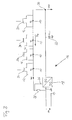
- eine erfindungsgemäße Vorrichtung gemäß einer ersten Ausführungsform mit einer Strombeschränkungseinrichtung, die eine Konstantstromquelle umfasst;
- Fig. 2
- eine erfindungsgemäße Vorrichtung gemäß einer zweiten Ausführungsform mit einer Strombeschränkungseinrichtung, die in den Überbrückungsstrompfaden angeordnete elektrische Widerstände umfasst; und
- Fig. 3
- eine erfindungsgemäße Vorrichtung gemäß einer dritten Ausführungsform mit einer Strombeschränkungseinrichtung, die MOSFETs mit erhöhten Durchlasswiderständen umfasst.
- Fig. 1
- a device according to the invention according to a first embodiment with a current limiting device comprising a constant current source;
- Fig. 2
- a device according to the invention according to a second embodiment with a current limiting device comprising in the bypass current paths arranged electrical resistors; and
- Fig. 3
- a device according to the invention according to a third embodiment with a current limiting device comprising MOSFETs with increased on-resistance.
In
Parallel zu jeder LED 10 ist jeweils ein Überbrückungsstrompfad 12 vorgesehen, der durch einen Schalter 14 geöffnet und geschlossen werden kann. Die Schalter 14 werden von einer auf Pulsweitenmodulation basierenden Steuerung angesteuert, mittels derer die einzelnen Schalter 14 selektiv mit unterschiedlichen Tastverhältnissen geöffnet und geschlossen werden können.Parallel to each
Zur Versorgung der LEDs 10 mit Strom ist eine Stromquelle 16 vorgesehen, die einen stromgesteuerten Aufwärtswandler 18 umfasst und an deren Ausgang 20 die Serienschaltung aus LEDs 10 angeschlossen ist. Der Soll-Wert des Ausgangsstroms des Aufwärtswandlers 18 ist so eingestellt, dass er im Wesentlichen dem Wert des Vorwärtsstroms der LEDs 10 entspricht, d.h. dem Strom, der durch eine LED 10 fließt, wenn die Vorwärtsspannung an dieser anliegt.To supply the
Die Stromquelle 16 umfasst einen Ausgangskondensator 22, in
Die Stromquelle 16 umfasst ferner einen Messwiderstand 28, der zwischen einen Versorgungseingang 24 und einen Rückkopplungseingang 26 des Aufwärtswandlers 18 geschaltet ist. Der Messwiderstand 28 stellt einen relativ kleinen elektrischen Widerstand dar und dient zur Messung des durch die LEDs 10 fließenden Stromes, in
Eine Konstantstromquelle bzw. -senke 30 ist zu der Serienschaltung der LEDs 10 in Serie geschaltet. Der Wert des von der Konstantstromquelle bzw. -senke 30 durchgelassenen Stromes entspricht im Wesentlichen dem Vorwärtsstrom der LEDs 10. Die Konstantstromquelle 30 wirkt als Strombeschränkungseinrichtung, wie nachfolgend genauer erläutert wird.A constant current source or sink 30 is connected in series with the series connection of the
Die Konstantstromquelle 30 beschränkt den durch die nicht überbrückten LEDs 10 fließenden Strom, indem sie für einen zusätzlichen Spannungsabfall sorgt, in
Da die Konstantstromquelle 30 so eingestellt ist, dass der von ihr durchgelassene Strom dem Vorwärtsstrom der LEDs 10 entspricht, nimmt der an der Konstantstromquelle 30 auftretende Spannungsabfall genau den Wert an, der dazu führt, dass an den nicht überbrückten LEDs 10 jeweils die Vorwärtsspannung der LEDs 10 abfällt und somit der Vorwärtsstrom der LEDs 10 durch die nicht überbrückten LEDs 10 fließt.Since the constant current source 30 is set so that the current passed through by it corresponds to the forward current of the
Durch die Beschränkung des im Falle des Überbrückens eines oder mehrerer LEDs 10 durch die nicht überbrückten LEDs 10 fließenden Stroms durch die Konstantstromquelle 30 wird verhindert, dass eine Entladung des Ausgangskondensators 22 in Folge der Überbrückung zu einer Beschädigung der nicht überbrückten LEDs 10 führt.By limiting the current flowing through the constant current source 30 in the case of bridging one or
Gleichzeitig wird durch die Strombeschränkung verhindert, dass sich die Spannung an dem Ausgangskondensator 22 bei einem raschen Ein- und Ausschalten der LEDs 10 mit einer dem Ein- und Ausschalten entsprechenden Frequenz erhöht bzw. reduziert, was aufgrund des umgekehrten piezoelektrischen Effekts zu einer unerwünschten Geräuschentwicklung am Ausgangskondensator 22 führen könnte.At the same time, the current limitation prevents the voltage at the
Werden die ausgeschalteten LEDs 10 mittels Unterbrechung des jeweiligen Überbrückungsstrompfades 12 durch Öffnen des jeweiligen Schalters 14 wieder eingeschaltet, so reduziert die Konstantstromquelle 30 umgekehrt die an ihr abfallende Spannung, sodass die an den LEDs 10 abfallende Spannung weniger stark oder gar nicht mehr reduziert wird und wiederum der Vorwärtsstrom durch die LEDs 10 fließt.If the switched-off
Die Strombeschränkungseinrichtung der Vorrichtung gemäß zweiter Ausführungsform umfasst elektrische Widerstände 32, die in den Überbrückungsstrompfaden 12 jeweils in Serie zu den Schaltern 14 geschaltet sind.The current limiting device of the device according to the second embodiment includes
Bei Überbrückung einer oder mehrerer LEDs 10 stellt der Ausgang 20 der Stromquelle 16 zumindest vorübergehend eine im Wesentlichen unverändert hohe Spannung bereit. Wären die Widerstände 32 nicht vorgesehen, so würde die über die überbrückten LEDs 10 abfallende Spannung nahezu auf null reduziert und die unverändert hohe von der Stromquelle 16 bereitgestellt Spannung würde sich über eine geringere Anzahl von LEDs 10 verteilen, sodass ein erhöhter Strom durch die nicht überbrückten LEDs 10 fließen würde.When bridging one or
Die in den Überbrückungsstrompfaden 12 angeordneten Widerstände 32 bewirken jedoch einen zusätzlichen Spannungsabfall in den geschlossenen Überbrückungsstrompfaden 12 infolge des durch die geschlossenen Überbrückungsstrompfade 12 und die darin angeordneten Widerstände 32 fließenden Stromes. Dieser zusätzliche Spannungsabfall reduziert die an den nicht überbrückten LEDs 10 abfallende Spannung entsprechend und verhindert somit eine übermäßige Spannungserhöhung an den nicht überbrückten LEDs 10, die zu einer Beschädigung dieser LEDs 10 führen könnte.However, the
Für die Werte der Widerstände 32 gelten folgende Bedingungen: Einerseits muss der Wert eines Widerstands 32 so klein sein, dass durch die überbrückte LED 10 deutlich weniger Strom fließt als durch die nicht überbrückte LED 10, damit die LED 10 wirksam ausgeschaltet ist. Andererseits müssen die Werte der Widerstände 32 so groß sein, dass bei der Überbrückung einer oder mehrerer LEDs 10 ein zusätzlicher Spannungsabfall durch die Widerstände 32 derart bewirkt wird, dass eine übermäßige Erhöhung der über die nicht überbrückten LEDs 10 abfallenden Spannung und daraus möglicherweise resultierende Beschädigung der nicht überbrückten LEDs 10 verhindert wird.On the one hand, the value of a
Bei der Festlegung der Werte der Widerstände 32 ist selbstverständlich auch zu berücksichtigen, wie viele der LEDs 10 typischerweise gleichzeitig aus- bzw. eingeschaltet sind.Of course, when determining the values of the
Bei der Vorrichtung gemäß dritter Ausführungsform ist die Strombeschränkungseinrichtung durch die Schalter der Überbrückungsstrompfade 12 gebildet. Bei den Schaltern handelt es sich in diesem Fall um MOSFET-Schalter 34, die - im Vergleich zu Schaltern 14 der ersten und zweiten Ausführungsform oder zu Schaltern, die in den Überbrückungsstrompfaden einer bekannten Vorrichtung verwendet werden - einen erhöhten elektrischen Durchlasswiderstand aufweisen.In the device according to the third embodiment, the current restricting means is constituted by the switches of the bypass
Die MOSFET-Schalter 34 dienen also nicht nur zum, ggf. pulsweitenmoduliert gesteuerten, Öffnen und Schließen des jeweiligen Überbrückungsstrompfads 12, sondern sie bewirken aufgrund ihres erhöhtem elektrischem Durchlasswiderstands im geschlossenen Zustand gleichzeitig eine Beschränkung des durch die nicht überbrückten LEDs 10 fließenden Stromes, entsprechend den in
Obwohl die voranstehend beschriebenen Ausführungsformen jeweils nur eine Art von Strombeschränkungseinrichtung umfassen, d.h. also entweder die Konstantstromquelle bzw. -senke 30, die Widerstände 32 und/oder die MOSFETs 34 mit erhöhtem elektrischem Durchlasswiderstand, ist nachzuvollziehen, dass auch eine Ausführungsform denkbar ist, die eine Kombination dieser verschiedenen Arten von Strombeschränkungseinrichtungen aufweist, beispielsweise die Konstantstromquelle 30 in Kombination mit den Widerständen 32 und/oder den MOSFETs 34 mit erhöhtem elektrischem Durchlasswiderstand.Although the embodiments described above each comprise only one type of current limiting device, ie either the constant current source 30, the
- 1010
- LEDLED
- 1212
- ÜberbrückungsstrompfadBridging current path
- 1414
- Schalterswitch
- 1616
- Stromquellepower source
- 1818
- Aufwärtswandlerboost converter
- 2020
- Ausgang der StromquelleOutput of the power source
- 2222
- Ausgangskondensatoroutput capacitor
- 2424
- Versorgungseingangsupply input
- 2626
- RückkopplungseingangFeedback input
- 2828
- Messwiderstandmeasuring resistor
- 3030
- Konstantstromquelle bzw. -senkeConstant current source or sink
- 3232
- elektrischer Widerstandelectrical resistance
- 3434
- MOSFET-SchalterMOSFET switch
Claims (14)
dadurch gekennzeichnet,
dass die Strombeschränkungseinrichtung von der Stromquelle (16) unabhängig ist.Device according to claim 1,
characterized,
that the current limiting means is independent of the current source (16).
dadurch gekennzeichnet,
dass jedem Leuchtmittel (10) ein eigener Überbrückungsstrompfad (12) zugeordnet ist.Apparatus according to claim 1 or claim 2,
characterized,
that each lighting means (10) is assigned its own bridging current path (12).
dadurch gekennzeichnet,
dass mindestens ein Leuchtmittel eine Leuchtdiode (10) ist und insbesondere alle Leuchtmittel Leuchtdioden (10) sind.Device according to at least one of the preceding claims,
characterized,
in that at least one light-emitting means is a light-emitting diode (10) and in particular all light-emitting means are light-emitting diodes (10).
dadurch gekennzeichnet,
dass die Strombeschränkungseinrichtung eine Konstantstromquelle bzw. -senke (30) umfasst, die zu den Leuchtmitteln (10) elektrisch in Serie geschaltet ist, wobei der von der Konstantstromquelle (30) gelieferte Strom insbesondere im Wesentlichen dem Vorwärtsstrom der in Serie geschalteten Leuchtmittel (10) entspricht.Device according to at least one of the preceding claims,
characterized,
in that the current limiting device comprises a constant current source or sink (30) which is electrically connected in series with the lighting means (10), the current supplied by the constant current source (30) in particular substantially corresponding to the forward current of the series connected lighting means (10). equivalent.
dadurch gekennzeichnet,
dass der von der Konstantstromquelle (30) durchgelassene Strom höher ist als der Nominalstrom der zur Stromversorgung der Leuchtmittel (10) vorgesehenen Stromquelle (16).Device according to claim 5,
characterized,
that from the constant current source (30) transmitted power is higher than the nominal current of the power supply of the lighting means (10) provided current source (16).
dadurch gekennzeichnet,
dass die Strombeschränkungseinrichtung einen elektrischen Widerstand (32) des Überbrückungsstrompfades (12) umfasst.Device according to at least one of the preceding claims,
characterized,
in that the current limiting device comprises an electrical resistance (32) of the bypass current path (12).
dadurch gekennzeichnet,
dass der elektrische Widerstand (32) mit einem Schalter (14) zum Öffnen und Schließen des Überbrückungsstrompfades (12) in Serie geschaltet ist.Device according to claim 7,
characterized,
in that the electrical resistor (32) is connected in series with a switch (14) for opening and closing the bypass current path (12).
dadurch gekennzeichnet,
dass die Strombeschränkungseinrichtung einen Schalter (34) zum Öffnen und Schließen des Überbrückungsstrompfades (12), insbesondere einen MOSFET-Schalter (34), umfasst, welcher Schalter (34) einen erhöhten elektrischen Durchlasswiderstand aufweist.Device according to at least one of the preceding claims,
characterized,
in that the current limiting device has a switch (34) for opening and closing the bypass current path (12), in particular a MOSFET switch (34), which switch (34) has an increased electrical on resistance.
dadurch gekennzeichnet,
dass der Wert des Gesamtwiderstands des Überbrückungsstrompfades (12) im geschlossenen Zustand so gewählt ist, dass die bei geschlossenem Überbrückungsstrompfad (12) über den Überbrückungsstrompfad (12) abfallende Spannung geringer ist als die zum normalen Betrieb des durch den Überbrückungsstrompfad (12) überbrückten Leuchtmittels (10) notwendige Spannung.Device according to at least one of the preceding claims,
characterized,
in that the value of the total resistance of the bypass current path (12) in the closed state is selected such that the voltage dropping across the bypass current path (12) when the bypass current path is closed is less than that for the normal operation of the light source bridged by the bypass current path (12) ( 10) necessary voltage.
dadurch gekennzeichnet,
dass zur Betätigung eines den Überbrückungsstrompfad (12) öffnenden bzw. schließenden Schalters (14; 34) eine auf einer Pulsweitenmodulation basierende Steuerung vorgesehen ist.Device according to at least one of the preceding claims,
characterized,
in that a control based on a pulse width modulation is provided for actuating a switch (14; 34) opening or closing the bypass current path (12).
dadurch gekennzeichnet,
dass die zur Versorgung der Leuchtmittel (10) mit Strom vorgesehene Stromquelle (16) eine Regelungsvorrichtung (18, 28) umfasst, die dazu ausgebildet ist, den Ausgangsstrom der Stromquelle (16) auf einen im Wesentlichen konstanten Wert zu regeln, wobei der im Wesentlichen konstante Ausgangsstrom insbesondere dem Vorwärtsstrom der Leuchtmittel (10) entspricht.Device according to at least one of the preceding claims,
characterized,
in that the current source (16) provided with power for supplying the lighting means (10) comprises a control device (18, 28) arranged to regulate the output current of the current source (16) to a substantially constant value, the substantially constant output current corresponds in particular to the forward current of the lighting means (10).
dadurch gekennzeichnet,
dass die Stromquelle (16) einen Schaltregler (18), insbesondere einen stromgesteuerten Aufwärtswandler (18), umfasst.Device according to at least one of the preceding claims,
characterized,
in that the current source (16) comprises a switching regulator (18), in particular a current-controlled boost converter (18).
dadurch gekennzeichnet,
dass die Stromquelle (16) einen Ausgangskondensator (22) umfasst.Device according to at least one of the preceding claims,
characterized,
in that the current source (16) comprises an output capacitor (22).
Priority Applications (2)
| Application Number | Priority Date | Filing Date | Title |
|---|---|---|---|
| EP10015239A EP2364059A3 (en) | 2008-12-08 | 2008-12-08 | Device with several lamps switched in series |
| EP08021297A EP2194760A1 (en) | 2008-12-08 | 2008-12-08 | Device with several lamps switched in series |
Applications Claiming Priority (1)
| Application Number | Priority Date | Filing Date | Title |
|---|---|---|---|
| EP08021297A EP2194760A1 (en) | 2008-12-08 | 2008-12-08 | Device with several lamps switched in series |
Publications (1)
| Publication Number | Publication Date |
|---|---|
| EP2194760A1 true EP2194760A1 (en) | 2010-06-09 |
Family
ID=40689294
Family Applications (2)
| Application Number | Title | Priority Date | Filing Date |
|---|---|---|---|
| EP08021297A Ceased EP2194760A1 (en) | 2008-12-08 | 2008-12-08 | Device with several lamps switched in series |
| EP10015239A Withdrawn EP2364059A3 (en) | 2008-12-08 | 2008-12-08 | Device with several lamps switched in series |
Family Applications After (1)
| Application Number | Title | Priority Date | Filing Date |
|---|---|---|---|
| EP10015239A Withdrawn EP2364059A3 (en) | 2008-12-08 | 2008-12-08 | Device with several lamps switched in series |
Country Status (1)
| Country | Link |
|---|---|
| EP (2) | EP2194760A1 (en) |
Cited By (1)
| Publication number | Priority date | Publication date | Assignee | Title |
|---|---|---|---|---|
| EP3182799A1 (en) * | 2015-12-18 | 2017-06-21 | odelo GmbH | Method for operating a light source of an automobile light comprising a plurality of semi-conductor light sources and light source for implementation of the method |
Citations (17)
| Publication number | Priority date | Publication date | Assignee | Title |
|---|---|---|---|---|
| EP1006506A1 (en) * | 1998-12-03 | 2000-06-07 | Hewlett-Packard Company | Optical vehicle display |
| DE10103611A1 (en) * | 2001-01-26 | 2002-08-01 | Insta Elektro Gmbh | Circuit arrangement for operating several light sources has light sources connected in series to electrical supply with considerably higher available voltage than microcomputer supply |
| EP1322139A1 (en) * | 2001-12-19 | 2003-06-25 | Toyoda Gosei Co., Ltd. | LED lamp apparatus for vehicles |
| EP1589519A2 (en) | 2004-04-20 | 2005-10-26 | Sony Corporation | Constant current driving device, backlight light source device, and color liquid crystal display device |
| US7012379B1 (en) * | 2003-03-27 | 2006-03-14 | Ilight Technologies, Inc. | Cuttable illumination device |
| US20060197722A1 (en) * | 2003-04-16 | 2006-09-07 | Chiaki Nakajima | Display led drive circuit |
| WO2007035883A2 (en) | 2005-09-20 | 2007-03-29 | California Micro Devices Corporation | Driving parallel strings of series connected leds |
| US20070108843A1 (en) * | 2005-11-17 | 2007-05-17 | Preston Nigel A | Series connected power supply for semiconductor-based vehicle lighting systems |
| WO2007069200A1 (en) | 2005-12-13 | 2007-06-21 | Koninklijke Philips Electronics N.V. | Led lighting device |
| US20070145914A1 (en) | 2005-12-22 | 2007-06-28 | Lg.Philips Lcd Co., Ltd. | Device for driving light emitting diode |
| US20070159736A1 (en) | 2006-01-12 | 2007-07-12 | Denso Corporation | Led-based lamp apparatus |
| US20070159750A1 (en) * | 2006-01-09 | 2007-07-12 | Powerdsine, Ltd. | Fault Detection Mechanism for LED Backlighting |
| US20070257623A1 (en) * | 2006-03-27 | 2007-11-08 | Texas Instruments, Incorporated | Highly efficient series string led driver with individual led control |
| DE102006031679A1 (en) * | 2006-07-08 | 2008-01-10 | Hella Kgaa Hueck & Co. | Circuit arrangement for the electrical control of a motor vehicle headlight |
| US20080068192A1 (en) * | 2006-09-20 | 2008-03-20 | Tir Technology Lp | Light emitting element control system and lighting system comprising same |
| EP1906711A1 (en) * | 2006-09-28 | 2008-04-02 | Valeo Vision | Device for checking a plurality of charges such as light sources and lighting and/or signalling device for a vehicle comprising such a checking device |
| EP2009960A2 (en) * | 2007-06-18 | 2008-12-31 | TridonicAtco Schweiz AG | LED protection |
Family Cites Families (5)
| Publication number | Priority date | Publication date | Assignee | Title |
|---|---|---|---|---|
| DE19728763B4 (en) * | 1997-07-07 | 2007-10-31 | Reitter & Schefenacker Gmbh & Co. Kg | Circuit device for protecting current-driven light sources, in particular LEDs, for signaling or lighting purposes |
| DE10329367B4 (en) * | 2003-03-28 | 2015-09-03 | Osram Opto Semiconductors Gmbh | LED array, LED module and use of the LED module in a signaling system |
| EP1964447B1 (en) * | 2005-12-14 | 2009-10-07 | Philips Intellectual Property & Standards GmbH | Circuit-arrangement for modulating an led and method for operating same |
| US7738229B2 (en) * | 2006-01-10 | 2010-06-15 | Bayco Products, Ltd. | Microprocessor-controlled multifunctioning light with intrinsically safe energy limiting |
| TWI345429B (en) * | 2006-11-13 | 2011-07-11 | Polytronics Technology Corp | Light emitting diode apparatus |
-
2008
- 2008-12-08 EP EP08021297A patent/EP2194760A1/en not_active Ceased
- 2008-12-08 EP EP10015239A patent/EP2364059A3/en not_active Withdrawn
Patent Citations (17)
| Publication number | Priority date | Publication date | Assignee | Title |
|---|---|---|---|---|
| EP1006506A1 (en) * | 1998-12-03 | 2000-06-07 | Hewlett-Packard Company | Optical vehicle display |
| DE10103611A1 (en) * | 2001-01-26 | 2002-08-01 | Insta Elektro Gmbh | Circuit arrangement for operating several light sources has light sources connected in series to electrical supply with considerably higher available voltage than microcomputer supply |
| EP1322139A1 (en) * | 2001-12-19 | 2003-06-25 | Toyoda Gosei Co., Ltd. | LED lamp apparatus for vehicles |
| US7012379B1 (en) * | 2003-03-27 | 2006-03-14 | Ilight Technologies, Inc. | Cuttable illumination device |
| US20060197722A1 (en) * | 2003-04-16 | 2006-09-07 | Chiaki Nakajima | Display led drive circuit |
| EP1589519A2 (en) | 2004-04-20 | 2005-10-26 | Sony Corporation | Constant current driving device, backlight light source device, and color liquid crystal display device |
| WO2007035883A2 (en) | 2005-09-20 | 2007-03-29 | California Micro Devices Corporation | Driving parallel strings of series connected leds |
| US20070108843A1 (en) * | 2005-11-17 | 2007-05-17 | Preston Nigel A | Series connected power supply for semiconductor-based vehicle lighting systems |
| WO2007069200A1 (en) | 2005-12-13 | 2007-06-21 | Koninklijke Philips Electronics N.V. | Led lighting device |
| US20070145914A1 (en) | 2005-12-22 | 2007-06-28 | Lg.Philips Lcd Co., Ltd. | Device for driving light emitting diode |
| US20070159750A1 (en) * | 2006-01-09 | 2007-07-12 | Powerdsine, Ltd. | Fault Detection Mechanism for LED Backlighting |
| US20070159736A1 (en) | 2006-01-12 | 2007-07-12 | Denso Corporation | Led-based lamp apparatus |
| US20070257623A1 (en) * | 2006-03-27 | 2007-11-08 | Texas Instruments, Incorporated | Highly efficient series string led driver with individual led control |
| DE102006031679A1 (en) * | 2006-07-08 | 2008-01-10 | Hella Kgaa Hueck & Co. | Circuit arrangement for the electrical control of a motor vehicle headlight |
| US20080068192A1 (en) * | 2006-09-20 | 2008-03-20 | Tir Technology Lp | Light emitting element control system and lighting system comprising same |
| EP1906711A1 (en) * | 2006-09-28 | 2008-04-02 | Valeo Vision | Device for checking a plurality of charges such as light sources and lighting and/or signalling device for a vehicle comprising such a checking device |
| EP2009960A2 (en) * | 2007-06-18 | 2008-12-31 | TridonicAtco Schweiz AG | LED protection |
Cited By (1)
| Publication number | Priority date | Publication date | Assignee | Title |
|---|---|---|---|---|
| EP3182799A1 (en) * | 2015-12-18 | 2017-06-21 | odelo GmbH | Method for operating a light source of an automobile light comprising a plurality of semi-conductor light sources and light source for implementation of the method |
Also Published As
| Publication number | Publication date |
|---|---|
| EP2364059A3 (en) | 2011-11-16 |
| EP2364059A2 (en) | 2011-09-07 |
Similar Documents
| Publication | Publication Date | Title |
|---|---|---|
| DE102006037342B4 (en) | Circuit for a motor vehicle, in particular for controlling a lighting device | |
| DE102008030365A1 (en) | Individual light sources i.e. LEDs, controlling device for lighting device in motor vehicle i.e. aircraft, has current regulation unit that is assigned to parallel circuits, where individual light sources are arranged in parallel circuits | |
| DE102006024607A1 (en) | Light system for motor vehicle, has two branches, where one branch is parallelly connected or adjustable to other branch, where bridge section is provided for adjustably connecting of two branches | |
| DE10346695B4 (en) | vehicle light | |
| DE102015104973B3 (en) | Arrangement and method for driving a plurality of light-emitting diodes arranged in a series circuit | |
| DE102007041131A1 (en) | Arrangement, use and method for driving light-emitting components | |
| DE102018208177B4 (en) | Light emission control device and vehicle lamp | |
| DE112011105504B4 (en) | LED lighting device | |
| WO2010121806A1 (en) | Circuit for a light-emitting diode assembly and light emitting diode module | |
| DE102007004877A1 (en) | Circuit arrangement for controlling LEDs, has control circuit supplying power dissipation signal for each power source circuit depending on power loss in power source circuits and producing control signal depending on dissipation signal | |
| DE102010002386A1 (en) | Device and method for driving light-emitting diode strands | |
| DE102008048197B4 (en) | Control device for a lighting device of a motor vehicle and motor vehicle lighting device | |
| DE102004034359B3 (en) | Circuit to operate a light signal for rail safety with parallel light diode chains has constant current source connected to a circuit element through a control reference voltage | |
| DE102020113565B3 (en) | Supply circuit and magnifier | |
| EP2745627B1 (en) | Led actuation for running light flashers | |
| DE112020005769T5 (en) | LED DRIVE DEVICE, LIGHTING DEVICE AND VEHICLE MOUNTED DISPLAY DEVICE | |
| EP2194760A1 (en) | Device with several lamps switched in series | |
| EP1945006A2 (en) | LED switching device | |
| DE102011016802B4 (en) | Control device for LED lighting devices | |
| EP3305026B1 (en) | Led light module for a lighting device for vehicles | |
| EP3503688B1 (en) | Flood light | |
| EP3393210B1 (en) | Switching assembly for operating lights | |
| DE102016210736A1 (en) | Arrangement and method for operating LEDs | |
| EP3264863B1 (en) | Method for providing power to consumers | |
| EP1395091B1 (en) | Lamp with a switching arrangement for controlling light-emitting diodes and method for adjusting such an arrangement |
Legal Events
| Date | Code | Title | Description |
|---|---|---|---|
| PUAI | Public reference made under article 153(3) epc to a published international application that has entered the european phase |
Free format text: ORIGINAL CODE: 0009012 |
|
| AK | Designated contracting states |
Kind code of ref document: A1 Designated state(s): AT BE BG CH CY CZ DE DK EE ES FI FR GB GR HR HU IE IS IT LI LT LU LV MC MT NL NO PL PT RO SE SI SK TR |
|
| AX | Request for extension of the european patent |
Extension state: AL BA MK RS |
|
| 17P | Request for examination filed |
Effective date: 20101203 |
|
| AKX | Designation fees paid |
Designated state(s): AT BE BG CH CY CZ DE DK EE ES FI FR GB GR HR HU IE IS IT LI LT LU LV MC MT NL NO PL PT RO SE SI SK TR |
|
| 17Q | First examination report despatched |
Effective date: 20130716 |
|
| RAP1 | Party data changed (applicant data changed or rights of an application transferred) |
Owner name: DELPHI INTERNATIONAL OPERATIONS LUXEMBOURG S.A R.L |
|
| STAA | Information on the status of an ep patent application or granted ep patent |
Free format text: STATUS: THE APPLICATION HAS BEEN REFUSED |
|
| 18R | Application refused |
Effective date: 20181220 |