EP2194612A1 - Electrical connector system - Google Patents
Electrical connector system Download PDFInfo
- Publication number
- EP2194612A1 EP2194612A1 EP09178099A EP09178099A EP2194612A1 EP 2194612 A1 EP2194612 A1 EP 2194612A1 EP 09178099 A EP09178099 A EP 09178099A EP 09178099 A EP09178099 A EP 09178099A EP 2194612 A1 EP2194612 A1 EP 2194612A1
- Authority
- EP
- European Patent Office
- Prior art keywords
- electrical
- wafer
- ground
- mating
- connector system
- Prior art date
- Legal status (The legal status is an assumption and is not a legal conclusion. Google has not performed a legal analysis and makes no representation as to the accuracy of the status listed.)
- Withdrawn
Links
Images


Classifications
-
- H—ELECTRICITY
- H01—ELECTRIC ELEMENTS
- H01R—ELECTRICALLY-CONDUCTIVE CONNECTIONS; STRUCTURAL ASSOCIATIONS OF A PLURALITY OF MUTUALLY-INSULATED ELECTRICAL CONNECTING ELEMENTS; COUPLING DEVICES; CURRENT COLLECTORS
- H01R13/00—Details of coupling devices of the kinds covered by groups H01R12/70 or H01R24/00 - H01R33/00
- H01R13/46—Bases; Cases
- H01R13/514—Bases; Cases composed as a modular blocks or assembly, i.e. composed of co-operating parts provided with contact members or holding contact members between them
-
- H—ELECTRICITY
- H01—ELECTRIC ELEMENTS
- H01R—ELECTRICALLY-CONDUCTIVE CONNECTIONS; STRUCTURAL ASSOCIATIONS OF A PLURALITY OF MUTUALLY-INSULATED ELECTRICAL CONNECTING ELEMENTS; COUPLING DEVICES; CURRENT COLLECTORS
- H01R13/00—Details of coupling devices of the kinds covered by groups H01R12/70 or H01R24/00 - H01R33/00
- H01R13/646—Details of coupling devices of the kinds covered by groups H01R12/70 or H01R24/00 - H01R33/00 specially adapted for high-frequency, e.g. structures providing an impedance match or phase match
- H01R13/6461—Means for preventing cross-talk
- H01R13/6471—Means for preventing cross-talk by special arrangement of ground and signal conductors, e.g. GSGS [Ground-Signal-Ground-Signal]
-
- H—ELECTRICITY
- H01—ELECTRIC ELEMENTS
- H01R—ELECTRICALLY-CONDUCTIVE CONNECTIONS; STRUCTURAL ASSOCIATIONS OF A PLURALITY OF MUTUALLY-INSULATED ELECTRICAL CONNECTING ELEMENTS; COUPLING DEVICES; CURRENT COLLECTORS
- H01R13/00—Details of coupling devices of the kinds covered by groups H01R12/70 or H01R24/00 - H01R33/00
- H01R13/648—Protective earth or shield arrangements on coupling devices, e.g. anti-static shielding
- H01R13/658—High frequency shielding arrangements, e.g. against EMI [Electro-Magnetic Interference] or EMP [Electro-Magnetic Pulse]
- H01R13/6581—Shield structure
- H01R13/6585—Shielding material individually surrounding or interposed between mutually spaced contacts
- H01R13/6586—Shielding material individually surrounding or interposed between mutually spaced contacts for separating multiple connector modules
- H01R13/6587—Shielding material individually surrounding or interposed between mutually spaced contacts for separating multiple connector modules for mounting on PCBs
-
- H—ELECTRICITY
- H01—ELECTRIC ELEMENTS
- H01R—ELECTRICALLY-CONDUCTIVE CONNECTIONS; STRUCTURAL ASSOCIATIONS OF A PLURALITY OF MUTUALLY-INSULATED ELECTRICAL CONNECTING ELEMENTS; COUPLING DEVICES; CURRENT COLLECTORS
- H01R13/00—Details of coupling devices of the kinds covered by groups H01R12/70 or H01R24/00 - H01R33/00
- H01R13/648—Protective earth or shield arrangements on coupling devices, e.g. anti-static shielding
- H01R13/658—High frequency shielding arrangements, e.g. against EMI [Electro-Magnetic Interference] or EMP [Electro-Magnetic Pulse]
- H01R13/6598—Shield material
- H01R13/6599—Dielectric material made conductive, e.g. plastic material coated with metal
-
- H—ELECTRICITY
- H01—ELECTRIC ELEMENTS
- H01R—ELECTRICALLY-CONDUCTIVE CONNECTIONS; STRUCTURAL ASSOCIATIONS OF A PLURALITY OF MUTUALLY-INSULATED ELECTRICAL CONNECTING ELEMENTS; COUPLING DEVICES; CURRENT COLLECTORS
- H01R13/00—Details of coupling devices of the kinds covered by groups H01R12/70 or H01R24/00 - H01R33/00
- H01R13/46—Bases; Cases
- H01R13/502—Bases; Cases composed of different pieces
- H01R13/506—Bases; Cases composed of different pieces assembled by snap action of the parts
-
- H—ELECTRICITY
- H05—ELECTRIC TECHNIQUES NOT OTHERWISE PROVIDED FOR
- H05K—PRINTED CIRCUITS; CASINGS OR CONSTRUCTIONAL DETAILS OF ELECTRIC APPARATUS; MANUFACTURE OF ASSEMBLAGES OF ELECTRICAL COMPONENTS
- H05K1/00—Printed circuits
- H05K1/02—Details
- H05K1/0213—Electrical arrangements not otherwise provided for
- H05K1/0216—Reduction of cross-talk, noise or electromagnetic interference
- H05K1/0218—Reduction of cross-talk, noise or electromagnetic interference by printed shielding conductors, ground planes or power plane
- H05K1/0219—Printed shielding conductors for shielding around or between signal conductors, e.g. coplanar or coaxial printed shielding conductors
- H05K1/0222—Printed shielding conductors for shielding around or between signal conductors, e.g. coplanar or coaxial printed shielding conductors for shielding around a single via or around a group of vias, e.g. coaxial vias or vias surrounded by a grounded via fence
-
- H—ELECTRICITY
- H05—ELECTRIC TECHNIQUES NOT OTHERWISE PROVIDED FOR
- H05K—PRINTED CIRCUITS; CASINGS OR CONSTRUCTIONAL DETAILS OF ELECTRIC APPARATUS; MANUFACTURE OF ASSEMBLAGES OF ELECTRICAL COMPONENTS
- H05K1/00—Printed circuits
- H05K1/02—Details
- H05K1/0213—Electrical arrangements not otherwise provided for
- H05K1/0237—High frequency adaptations
- H05K1/0245—Lay-out of balanced signal pairs, e.g. differential lines or twisted lines
-
- H—ELECTRICITY
- H05—ELECTRIC TECHNIQUES NOT OTHERWISE PROVIDED FOR
- H05K—PRINTED CIRCUITS; CASINGS OR CONSTRUCTIONAL DETAILS OF ELECTRIC APPARATUS; MANUFACTURE OF ASSEMBLAGES OF ELECTRICAL COMPONENTS
- H05K1/00—Printed circuits
- H05K1/02—Details
- H05K1/11—Printed elements for providing electric connections to or between printed circuits
- H05K1/115—Via connections; Lands around holes or via connections
- H05K1/116—Lands, clearance holes or other lay-out details concerning the surrounding of a via
Definitions
- backplane connector systems are typically used to connect a first substrate 2, such as a printed circuit board, in parallel (perpendicular) with a second substrate 3, such as another printed circuit board.
- first substrate 2 such as a printed circuit board
- second substrate 3 such as another printed circuit board.
- an electrical connector system for mounting a substrate comprises a plurality of wafer assemblies.
- Each of the wafer assemblies comprises a plurality of electrical contacts, a frame, and a plurality of ground-able contacts.
- the frame defines a first side and a second side, the first side defining a plurality of channels, each channel comprising a conductive surface and each channel adapted to receive at least one electrical contact of the plurality of electrical contacts.
- the frame further defines a plurality of apertures extending into the conductive surfaces of the plurality of channels, the apertures spaced apart from one another and positioned between the channels of the plurality of channels.
- Each ground-able contact is positioned within an aperture of the plurality of apertures.
- a wafer housing positions the wafer assemblies adjacent to one another in the electrical connector system.
- Figure 1 is a diagram of a backplane connector system connecting a first substrate to a second substrate.
- Figure 2 is a perspective view of a portion of a high-speed backplane connector system.
- Figure 3 is a partially exploded view of the high-speed backplane connector system of Figure 2 .
- Figure 4 is a perspective view of a wafer assembly.
- Figure 5 is a partially exploded view of the wafer assembly of Figure 4 .
- Figure 6a is a perspective view of a center frame of a wafer assembly.
- Figure 6b is another perspective view of a center frame of a wafer assembly.
- Figure 7a is a partially exploded view of the wafer assembly of Fig. 4 .
- Figure 7b is a cross-sectional view of a center frame.
- Figure 8 illustrates a closed-band electrical mating connector
- Figure 9a illustrates a tri-beam electrical mating connector.
- Figure 9b illustrates a dual-beam electrical mating connector.
- Figure 9c illustrates additional implementations of electrical mating connectors.
- Figure 9d illustrates a mirrored pair of electrical mating connectors.
- Figure 9e illustrates a plurality of mirrored pairs of electrical mating connectors.
- Figure 10 illustrates a plurality of ground tabs.
- Figure 11 is a perspective view of a ground tab.
- Figure 12 is another perspective view of a wafer assembly.
- Figure 13 illustrates an organizer
- Figure 14 is a perspective view of a wafer housing.
- Figure 15 is an additional perspective view of a wafer housing.
- Figure 16 is a cross-sectional view of a plurality of wafer assemblies.
- Figure 17a is a side view of a center frame that includes a plurality of mating ridges and a plurality of mating recesses.
- Figure 17b is a cross-sectional view of a plurality of wafer assemblies that include a plurality of mating ridges and a plurality of mating recesses.
- Figure 18a is a perspective view of a header unit.
- Figure 18b illustrates one implementation a mating face of a header unit.
- Figure 18c illustrates another implementation of a mating face of a header unit.
- Figure 18d illustrates a pair of signal pins substantially surrounded by a C-shaped ground shield and a ground tab.
- Figure 19a illustrates one implementation of a signal pin of a header unit.
- Figure 19b illustrates another implementation of a signal pin of a header unit.
- Figure 19c illustrates yet another implementation of a signal pin of a header unit.
- Figure 19d illustrates a mirrored pair of signal pins of a header unit.
- Figure 20a is a perspective view of a C-shaped ground shield of a header unit.
- Figure 20b is another view of the C-shaped ground shield of Figure 20a of a header unit.
- Figure 20c illustrates another implementation of a C-shaped ground shield of a header unit.
- Figure 20d illustrates yet another implementation of a C-shaped ground shield of a header unit.
- Figure 20e illustrates another implementation of a C-shaped ground shield of a header unit.
- Figure 21 illustrates one implementation of a ground tab of a header unit.
- Figure 22 is a perspective view of a high-speed backplane connector system.
- Figure 23 is another perspective view of the high-speed backplane connector system of Figure 22 .
- Figure 24 is yet another perspective view of the high-speed backplane connector system of Figure 22 .
- Figure 25 illustrates one implementation of a mounting face of a header unit.
- Figure 26a illustrates a noise-cancelling footprint of one implementation of a high-speed backplane connector system.
- Figure 26b is an enlarged view of a portion of the noise-cancelling footprint of Figure 26a .
- Figure 27a illustrates another implementation of a mounting face of a header unit.
- Figure 27b illustrates a noise-cancelling footprint of the mounting face of the header unit of Figure 27a .
- Figure 27c illustrates yet another implementation of a mounting face of a header unit.
- Figure 27d illustrates a noise-cancelling array of the mounting face of the header unit of Figure 27c .
- Figure 28a illustrates a substrate footprint that may be used with high-speed backplane connector systems.
- Figure 28b illustrates an enlarged view of the substrate footprint of Figure 28a .
- Figure 28c illustrates a substrate footprint that may be used with high-speed backplane connector systems.
- Figure 28d illustrates an enlarged view of the substrate footprint of Figure 28c .
- Figure 29a illustrates a header unit including a guidance post and a mating key.
- Figure 29b illustrates a wafer housing for use with the header unit of Figure 28a .
- Figure 30a illustrates a mounting end of a plurality of wafer assemblies.
- Figure 30b is an enlarged view of a portion of a noise-cancelling footprint of the mounting end of the plurality of wafer assemblies illustrates in Figure 29a .
- Figure 31a is a perspective view of a tie bar.
- Figure 31b illustrates a tie bar engaging a plurality of wafer assemblies.
- Figure 32a is a performance plot illustrating insertion loss vs. frequency for the high-speed backplane connector system of Figure 2 .
- Figure 32b is a performance plot illustrating return loss vs. frequency for the high-speed backplane connector system of Figure 2 .
- Figure 32c is a performance plot illustrating near-end crosstalk noise vs. frequency for the high-speed backplane connector system of Figure 2 .
- Figure 32d is a performance plot illustrating far-end crosstalk noise vs. frequency for the high-speed connector system of Figure 2 .
- Figure 33 is a perspective view of another implementation of a high-speed backplane connector system.
- Figure 34 is an exploded view of a wafer assembly.
- Figure 35a is a front perspective view of a center frame.
- Figure 35b is a side view of a center frame.
- Figure 35c is a rear perspective view of a center frame.
- Figure 36 illustrates front and side views of a wafer assembly.
- Figure 37a is a front view of a wafer housing.
- Figure 37b is a rear view of a wafer housing.
- Figure 38 is a cross-sectional view of a plurality of wafer assemblies.
- Figure 39a illustrates an unmated header unit, wafer housing, and plurality of wafer assemblies.
- Figure 39b illustrates a mated header unit, wafer housing, and plurality of wafer assemblies.
- Figure 39c illustrates a rear perspective view of an unmated header unit, wafer housing, and plurality of wafer assemblies.
- Figure 39d illustrates an enlarged rear perspective view of an unmated header unit, wafer housing, and plurality of wafer assemblies.
- Figure 40a is a performance plot illustrating insertion loss vs. frequency for the high-speed backplane connector system of Figure 33 .
- Figure 40b is a performance plot illustrating return loss vs. frequency for the high-speed backplane connector system of Figure 33 .
- Figure 40c is a performance plot illustrating near-end crosstalk noise vs. frequency for the high-speed backplane connector system of Figure 33 .
- Figure 40d is a performance plot illustrating far-end crosstalk noise vs. frequency for the high-speed connector system of Figure 33 .
- Figure 41 is a perspective view, and a partially exploded view, of another implementation of a high-speed backplane connector.
- Figure 42 is another perspective view, and partially exploded view, of the high-speed backplane connector of Figure 41 .
- Figure 43a is a perspective view of a wafer assembly.
- Figure 43b is a partially exploded view of a wafer assembly.
- Figure 44a is a perspective view of a housing and an embedded ground frame.
- Figure 44b is a perspective view of a ground frame that may be positioned at a side of a housing.
- Figure 44c is a perspective view of a wafer assembly with a ground frame positioned at a side of a housing.
- Figure 45 is a cross-sectional view of a wafer assembly.
- Figure 46 illustrates front and side views of a wafer assembly.
- Figure 47a illustrates one implementation of a ground shield
- Figure 47b illustrates an assembled wafer assembly with a ground shield spanning two electrical mating connectors and electrically commoned to the first and second housings.
- Figures 47c and 47d are additional illustrations of an assembled wafer assembly with a ground shield spanning two electrical mating connectors and electrically commoned to the first and second housings.
- Figure 48a is a perspective view of a mating face of a header unit.
- Figure 48b is a perspective view of a mating face of a wafer housing.
- Figure 49 illustrates an air gap between two adjacent wafer assemblies.
- Figure 50a is a perspective view of an unmated high-speed backplane connector system.
- Figure 50b is a perspective view of a mated high-speed backplane connector system.
- Figure 51a is a perspective view of a plurality of wafer assemblies and an organizer.
- Figure 51b is another perspective view of a plurality of wafer assemblies and an organizer.
- Figure 52a is a perspective view of one implementation of a mounting-face organizer.
- Figure 52b is an enlarged view of the mounting-face organizer of Figure 52a positioned at a mounting face of a plurality of wafer assemblies.
- Figure 52c is a perspective view of the high-speed backplane connector of Figure 41 with the mounting-face organizer of Figure 52a .
- Figure 53a is a perspective view of another implementation of a mounting-face organizer
- Figure 53b illustrates an air gap at a mounting end of a plurality of wafer assemblies created by a plurality of projections extending through the mounting-face organizer of Figure 53a .
- Figures 53c and 53d are additional illustrations of a plurality of projections extending through the mounting face organizer of Figure 53a .
- Figure 54a is a performance plot illustrating insertion loss vs. frequency for the high-speed backplane connector system of Figure 41 .
- Figure 54b is a performance plot illustrating return loss vs. frequency for the high-speed backplane connector system of Figure 41 .
- Figure 54c is a performance plot illustrating near-end crosstalk noise vs. frequency for the high-speed backplane connector system of Figure 41 .
- Figure 54d is a performance plot illustrating far-end crosstalk noise vs. frequency for the high-speed connector system of Figure 41 .
- Figure 55 is a perspective view of a portion of yet another implementation of a high-speed backplane connector system.
- Figure 56a is a perspective view of a ground shield.
- Figure 56b is a perspective view of a plurality of housing assemblies.
- Figure 56c is another perspective view of the ground shield.
- Figure 57a illustrates a plurality of unbent electrical contact assemblies.
- Figure 57b illustrates a plurality of bent electrical contact assemblies.
- Figure 58 is an enlarged view of a differential pair of electrical mating connectors.
- Figure 59 illustrates a noise-canceling footprint of a mounting end of a ground shield and a matrix of electrical contact assemblies.
- Figure 60 is a front view of a mounting end organizer.
- Figure 61a is a side view of a portion of a high-speed backplane connector system.
- Figure 61b is a perspective view of a portion of a high-speed backplane connector system.
- Figure 62 illustrates a ground shield and plurality of wafer assemblies mating with a header unit.
- Figure 63a is a performance plot illustrating insertion loss vs. frequency for the high-speed backplane connector system of Figure 55 .
- Figure 63b is a performance plot illustrating return loss vs. frequency for the high-speed backplane connector system of Figure 55 .
- Figure 63c is a performance plot illustrating near-end crosstalk noise vs. frequency for the high-speed backplane connector system of Figure 55 .
- Figure 63d is a performance plot illustrating far-end crosstalk noise vs. frequency for the high-speed connector system of Figure 55 .
- Figure 64 is an illustration of a mating end of a plurality of wafer assemblies.
- Figure 65 is another illustration of a mating end of a plurality of wafer assemblies.
- Figure 66a is a perspective view of a header assembly.
- Figure 66b is a side view of the header assembly of Figure 66a .
- Figure 67 illustrates a mounting pin layout of the header assembly of Figs. 66a and 66b .
- Figure 68 is an illustration of a mating end of one implementations of a plurality of wafer assemblies.
- Figure 69 is an illustration of a mating end of another implementation of a plurality of wafer assemblies.
- Figure 70 is an illustration of a mating end of yet another implementation of a plurality of wafer assemblies.
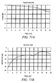
- Figure 71a is a performance plot illustrating insertion loss vs. frequency for a high-speed backplane connector system including the wafer assembly design of Figures 66-70 .
- Figure 71b is a performance plot illustrating return loss vs. frequency for the high-speed backplane connector system including the wafer assembly design of Figures 66-70 .
- Figure 71c is a performance plot illustrating near-end crosstalk noise vs. frequency for the high-speed backplane connector system including the wafer assembly design of Figures 66-70 .
- Figure 71d is a performance plot illustrating far-end crosstalk noise vs. frequency for the high-speed connector system including the wafer assembly design of Figures 66-70 .
- the present disclosure is directed to high-speed backplane connectors systems for mounting a substrate that are capable of operating at speeds of up to at least 25 Gbps, while in some implementations also providing pin densities of at least 50 pairs of electrical connectors per inch.
- implementations of the disclosed high-speed connector systems may provide ground shields and/or other ground structures that substantially encapsulate electrical connector pairs, which may be differential electrical connector pairs, in a three-dimensional manner throughout a backplane footprint, a backplane connector, and a daughtercard footprint.
- implementations of the disclosed high-speed connector systems may provide substantially identical geometry between each connector of an electrical connector pair to prevent longitudinal moding.
- a first high-speed backplane connector system 100 is described with respect to Figs 2-32 .
- the high-speed backplane connector 100 includes a plurality of wafer assemblies 102 that, as explained in more detail below, are positioned adjacent to one another within the connector system 100 by a wafer housing 104.
- Each wafer assembly 106 of the plurality of wafer assemblies 102 includes a center frame 108, a first array of electrical contacts 110 (also known as a first lead frame assembly), a second array of electrical contacts 112 (also known as a second lead frame assembly), a plurality of ground tabs 132, and an organizer 134.
- the center frame 108 comprises a plated plastic or diecast ground wafer such as tin (Sn) over nickel (Ni) plated or a zinc (Zn) die cast
- the first and second arrays of electrical contacts 110, 112 comprise phosphor bronze and gold (Au) or tin (Sn) over nickel (Ni) plating.
- the center frame 108 may comprise an aluminum (AI) die cast, a conductive polymer, a metal injection molding, or any other type of metal; the first and second arrays of electrical contacts 110, 112 may comprise any copper (Cu) alloy material; and the platings could be any noble metal such as palladium (Pd) or an alloy such as Pd-Ni or Au flashed Pd in the contact area, tin (Sn) or nickel (Ni) in the mounting area, and nickel (Ni) in the underplating or base plating.
- Pd palladium
- Au flashed Pd tin
- Sn tin
- Ni nickel
- Ni nickel
- the center frame 108 defines a first side 114 and a second side 116 opposing the first side 114.
- the first side 114 comprises a conductive surface that defines a plurality of first channels 118.
- each channel of the plurality of first channels 118 is lined with an insulation layer 119, such as an overmolded plastic dielectric, so that when the first array of electrical contacts 110 is positioned substantially within the plurality of first channels 118, the insulation layer 119 electrically isolates the electrical contacts from the conductive surface of the first side 114.
- the second side 116 also comprises a conductive surface that defines a plurality of second channels 120.
- each channel of the plurality of second channels 120 is lined with an insulation layer 121, such as an overmolded plastic dielectric, so that when the second array of electrical contacts 112 is positioned substantially within the plurality of second channels 120, the insulation layer 121 electrically isolates the electrical contacts from the conductive surface of the second side 116.
- the center frame includes an embedded conductive shield 115 positioned between the first and second sides 114, 116.
- the conductive shield 115 is electrically connected to the conductive surfaces of the first side 114 and the conductive surface of the second side 116.
- the first array of electrical contacts 110 when assembled, is positioned substantially within the plurality of channels 118 of the first side 114 of the center frame 108 and the second array of electrical contacts 112 is positioned substantially within the plurality of channels 120 of the second side 116 of the center frame 108.
- each electrical contact of the first array of electrical contacts 110 is positioned adjacent to an electrical contact of the second array of electrical contacts 112.
- the first and second arrays of electrical contacts 110, 112 are positioned in the plurality of channels 118, 120 such that a distance between adjacent electrical contacts is substantially the same throughout the wafer assembly 106. Together, the adjacent electrical contacts of the first and second arrays of electrical contacts 110, 112 form an electrical contact pair 130.
- the electrical contact pair 130 may be a differential pair of electrical contacts.
- electrical mating connectors 129 of the first and second array of electrical contacts 110, 112 extend away from a mating end 131 of the wafer assembly 106.
- the electrical mating connectors 129 are closed-band shaped as shown in Figs. 7a and 8 , where in other implementations, the electrical mating connectors 129 are tri-beam shaped as shown in Fig. 9a or dual-beam shaped as shown in Fig. 9b .
- Other mating connector styles could have a multiplicity of beams. Examples of yet other implementations of electrical mating connectors 129 are shown in Fig. 9c .
- the tri-beam shaped, dual-beam shaped, or closed-band shaped electrical mating connectors 129 provide improved reliability in a dusty environment; provide improved performance in a non-stable environment, such as an environment with vibration or physical shock; result in lower contact resistance due to parallel electrical paths; and the closed-band or tri-beam shaped arrangements provide improved electromagnetic properties due to the fact energy tends to radiate from sharp corners of electrical mating connectors 129 with a boxier geometry.
- the electrical contact of the first array of electrical contacts 110 mirrors the adjacent electrical contact of the second array of electrical contacts 112. It will be appreciated that mirroring the electrical contacts of the electrical contact pair provides advantages in manufacturing as well as column-to-column consistency for high-speed electrical performance, while still providing a unique structure in pairs of two columns.
- substrate engagement elements 172 such as electrical contact mounting pins, of the first and second array of electrical contacts 110, 112 also extend away from a mounting end 170 of the wafer assembly 106.
- the first array of electrical contacts 110 includes a first spacer 122 and a second spacer 124 to space each electrical contact appropriately for insertion substantially within the plurality of first channels 118.
- the second array of electrical contacts 112 includes a first spacer 126 and a second spacer 128 to space each electrical contact appropriately for insertion within the plurality of second channels 120.
- the first and second spacers 122, 124 of the first array of electrical contacts 110 and the first and second spacers 126, 128 of the second array of electrical contacts 112 comprise molded plastic.
- the first and second arrays of electrical contacts 110, 112 are substantially positioned within the plurality of channels 118, 120, the first spacer 122 of the first array of electrical contacts 110 abuts the first spacer 126 of the second array of electrical contacts 112.
- first spacer 122 of the first array of electrical contacts 110 may define a tooth-shaped side, or a wave-shaped side
- first spacer 126 of the second array of electrical contacts may define a complementary tooth-shaped side, or a complementary wave-shaped side, so that when the first spacers 122, 126 abut, the complementary sides of the first spacers 122, 126 engage and mate.
- the plurality of ground tabs 132 is positioned at the mating end 131 of the wafer assembly 106 to extend away from the center frame 108.
- the ground tabs 132 are electrically connected to at least one of the first and second sides 114, 116 of the central frame 108.
- a ground tab 132 is paddle shaped and at least one ground tab 132 is positioned above and below each electrical contact pair 130 at the mating end 131 of the wafer assembly.
- the ground tabs comprise tin (Sn) over nickel (Ni) plated brass or other electrically conductive platings or base metals.
- the organizer 134 is positioned at the mating end 131 of the wafer assembly 106.
- the organizer comprises a plurality of apertures 135 that allow the electrical mating connectors 129 and ground tabs 132 extending from the wafer assembly 106 to pass through the organizer 134 when the organizer 134 is positioned at the mating end 131 of the wafer assembly 106.
- the organizer serves to securely lock the center frame 108, first array of electrical contacts 110, second array of electrical contacts 112, and ground tabs 132 together.
- the wafer housing 104 engages the plurality of wafer assemblies 102 at the mating end 131 of each wafer assembly 106.
- the wafer housing 104 accepts the electrical mating connectors 129 and ground tabs 132 extending from the plurality of wafer assemblies 102, and positions each wafer assembly 106 adjacent to another wafer assembly 106 of the plurality of wafer assemblies 102.
- two wafer assemblies 106 when positioned adjacent to one another, two wafer assemblies 106 define a plurality of air gaps 134 substantially between a length of an electrical contact of a first wafer assembly 106 and a length of an electrical contact of a second wafer assembly 106.
- Each air gap 134 serves to electrically isolate the electrical contacts positioned with the air gap 134 of the wafer assemblies 106.
- each center frame 108 defines a plurality of mating ridges 109 extending from the first side 114 of the center frame 108 and a plurality of mating ridges 109 extending from the second side 116 of the center frame 108. Additionally, each center frame defines a plurality of mating recesses 111 at the first side 114 of the center frame 108 and a plurality of mating recesses 111 at the second side 116 of the center frame 108.
- one of the mating ridges 109 and one of the mating recesses 111 are positioned between each channel of the plurality of second channels 120 on the second side 116 of the center frame 108. Further, mating ridges 109 and mating recesses 111 are positioned between each channel of the plurality of first channels 118 on the first side 114 of the center frame 108 that complement the mating ridges 109 and mating recesses 111 on the second side. Therefore, as shown in Fig.
- the resulting overlap 113 provides for improved contact between adjacent wafer assemblies 106. Additionally, the resulting overlap 113 disrupts a direct signal path between adjacent air gaps 134, thereby improving the performance of signals traveling on the electrical contacts of the first and second arrays of electrical contacts 110, 112 positioned in the air gaps 134.
- the connector system 100 further includes a header module 136 adapted to mate with the wafer housing 104.
- a mating face of the header module 136 that engages the wafer housing 104 includes a plurality of C-shaped ground shields 138, a row of ground tabs 140, and a plurality of signal pin pairs 142.
- the header module 136 may comprise a liquid crystal polymer (LCP) insulator;
- the signal pin pairs 142 comprise phosphor bronze base material and, gold (Au), and tin (Sn) platings over nickel (Ni) plating;
- the ground shields 138 and ground tabs 140 comprise brass base material with tin (Sn) over nickel (Ni) plating.
- Other electrically conductive base materials and platings can be used to construct signal pins, ground shields, and ground tabs.
- Other polymers can be used to construct housings.
- the row of ground tabs 140 is positioned along one side of the mating face of the header module 136.
- a first row 144 of the plurality of C-shaped ground shields 138 is positioned above the row of ground tabs 140 at an open end of the C-shaped ground shields 138 so that a signal pin pair 146 of the plurality of signal pin pairs 142 is substantially surrounded by a ground tab and a C-shaped ground shield.
- a second row 148 of the plurality of C-shaped ground shields 138 is positioned above the first row 144 of the plurality of C-shaped ground shields 138 at an open end of C-shaped ground shields of the second row 148 so that a signal pin pair 150 of the plurality of signal pin pairs 142 is substantially surrounded by an edge of a C-shaped ground shield of the first row 144 and a C-shaped ground shield of the second row 148. It will be appreciated that this pattern is repeated so that each subsequent signal pin pair 142 is substantially surrounded by an edge of a first C-shaped ground shield and a second C-shaped ground shield.
- each C-shaped ground shield is horizontal and perpendicular to a wafer assembly 106, and spans both an electrical contact of the first array of electrical contacts 110 and an electrical contact of the second array of electrical contacts of the wafer assembly 106.
- each signal pin pair 142 is positioned on the header module 136 such that a distance between a first signal pin 143 of the signal pin pair and a point on a C-shaped ground shield or ground tab (See distances a, b, and c) is substantially equal to a distance between a second signal pin 145 of the signal pin pair and a corresponding point on the C-shaped ground shield or ground tab (See distances a', b', and c').
- This symmetry between the first and second signal pins 143, 145 and the C-shaped ground shield or ground tab provides improved manageability of signals traveling on the signal pin pair 142.
- each signal pin of the plurality of signal pin pairs 142 is a vertical rounded pin as shown in Fig. 19a so that as the header module 136 receives the wafer housing 104, the wafer housing 104 receives the plurality of signal pin pairs 142, and the plurality of signal pin pairs 142 are received by, and engage the electrical mating connectors 129 of the first and second arrays of electrical contacts 110, 112 that are extending from the plurality of wafer assemblies 102.
- each signal pin of the plurality of signal pin pairs 142 is a vertical U-shaped pin as shown in Fig. 19b or Fig. 19c . It will be appreciated that the U-shaped pin provides for efficient manufacturing because dual gage material is not required to make a mating end and a mounting end.
- the first signal pin 143 of the signal pin pair mirrors the adjacent second signal pin 145 of the signal pin pair. It will be appreciated that mirroring the signal pins of the signal pin pair 142 provides advantages in manufacturing as well in high-speed electrical performance, while still providing a unique structure for the signal pin pairs.
- each C-shaped ground shield 138 and each ground tab 140 of the header module 136 may include one or more mating interfaces 152 as shown in Figs. 20a , 20b , 20c , 20d , 20e , and 21 . Accordingly, as the header module 136 receives the wafer housing 104 as shown in Figs. 22-24 , the wafer housing 104 receives the ground shields 138 and ground tabs 140 of the header module 136, and the C-shaped ground shields 138 and ground tabs 140 of the header module 136 engage the ground tabs 132 extending from the plurality of wafer assemblies 102 at at least the one or more mating interfaces 152.
- each set of engaged signal pin pair 142 and electrical mating connectors 129 of the first and second arrays of electrical contacts 110, 112 is substantially surrounded by, and electrically isolated by, a ground tab 132 of a wafer assembly 106, a C-shaped ground shield 136 of the header module 136 and one of a ground tab 140 of the header module 136 or a side of another C-shaped ground shield 136 of the header module 136.
- each C-shaped ground shield and ground tab of the header module 136 additionally defines one or more substrate engagement elements 156, such as a ground mounting pin, each of which is configured to engage a substrate at a via of the substrate.
- each signal pin of the header module 136 additionally defines a substrate engagement element 158, such as a signal mounting pin, that is configured to engage a substrate at a via of the substrate.
- each ground mounting pin 156 and signal mounting pin 158 defines a broadside 161 and an edge 163 that is smaller than the broadside 161.
- the ground mounting pins 156 and signal mounting pins 158 extend through the header module 136, and extend away from a mounting face of the header module 136.
- the ground mounting pins 156 and signal mounting pins 158 are used to engage a substrate such as a backplane circuit board or a daughtercard circuit board.
- each pair of signal mounting pins 158 is positioned in one of two orientations, such as broadside coupled or edge coupled. In other implementations, each pair of signal mounting pins 156 is positioned in one of two orientations where in a first orientation, a pair of signal mounting pins 158 are aligned so that the broadsides 161 of the pair are substantially parallel to a substrate, and in a second orientation, a pair of signal mounting pins 158 are aligned so that the broadsides 161 of the pair are substantially perpendicular to the substrate. As discussed above with respect to Figs.
- the signal pins of a pair of signal mounting pins 158 may be positioned on the header module 136 such that one signal pin of the pair of signal mounting pins 158 mirrors the adjacent signal pin of the pair of signal mounting pins 158.
- the ground mounting pins 156 and signal mounting pins 158 may be positioned on the header module 136 as shown in Figs. 25 , 26a and 26b to create a noise-canceling footprint 159.
- an orientation of a pair of signal mounting pins 160 is offset from an orientation of each adjacent pair of signal mounting pins 162 that is not separated from signal mounting pins 160 by a ground mounting pin 163.
- the orientation of a pair of signal mounting pins 160 may be offset by 90 degrees from the orientation of each pair of signal mounting pins 162 that is not separated from the pair of signal mounting pins 160 by a ground mounting pin 163.
- each pair of signal mounting pins 158 is positioned in the same orientation.
- C-shaped ground shields 138 and ground tabs 140 with multiple ground mounting pins 156 are then positioned around the signal pin pairs 142 as described above.
- the ground mounting pins 156 of the C-shaped ground shields 138 and ground tabs 140 are positioned such that at least one ground mounting pin 156 is positioned between a signal mounting pin 158 of a first signal pin pair 142 and a signal mounting pin 158 of adjacent signal pin pairs 142.
- the C-shaped ground shields 138 and ground tabs 140 may include ground mounting pins 156 positioned at locations 157.
- each pair of signal mounting pins 158 is positioned in the same orientation.
- C-shaped ground shields 138 and ground tabs 140 with multiple ground mounting pins 156 are then positioned around the signal pin pairs 142 as described above.
- the ground mounting pins 156 are positioned such that at least one ground mounting pin 156 is positioned between a signal mounting pin 158 of a first signal pin pair 142 and a signal mounting pin 158 of adjacent signal pin pairs 142.
- the signal mounting pins 158 of the header module 136 engage a substrate at a plurality of first vias positioned on the substrate, wherein the plurality of first vias are arranged in a matrix of rows and columns and able to provide mounting of the electrical connector.
- Each first via is associated with one of its closest neighboring first vias to form a pair of first vias.
- the pair of first vias is configured to receive signal mounting pins 158 of one of the signal pin pairs 142.
- the ground mounting pins 156 of the C-shaped ground shields 138 and ground tabs 140 of the header module 136 engage a substrate at a plurality of second vias positioned on the substrate.
- the plurality of second vias are configured to be electrically commoned to one another to provide a common ground, and are positioned amongst the plurality of first vias such that there is at least one second via positioned directly between each first via and any of the closest non-paired first via neighbors.
- substrate footprints that may receive the mounting end of header module 156, or as explained in more detail below the mounting end of the plurality of wafer assemblies 102, are illustrated in Figs. 28a , 28b , 28c , and 28d . It will be appreciated that substrate footprints should be able to maintain an impedance of a system, such as 100 Ohms differentially, while also minimizing pair-to-pair crosstalk noise. Substrate footprints should also provide adequate routing channels for differential pairs while preserving skew-free routing and connector design. These tasks should be completed for substrate footprints that are highly dense while minding substrate aspect ratio limits where vias must be large enough (given a substrate thickness) in order to ensure reliable manufacturing.
- Figs. 28a and 28b One implementation of an optimized in-row-differential substrate footprint that may accomplish these tasks is illustrated in Figs. 28a and 28b .
- This substrate footprint is oriented "in-row" so as to reduce or eliminate routing skew and connector skew. Further, the substrate footprint provides improved performance by providing multiple points of contact 165 for connector grounds shields to the printed circuit board around points of contact 167 for signal pins or electrical contacts. Additionally, the substrate footprint provides the ability to route all differential pairs out of an 8-row footprint in only four layers while minimizing intra-layer, inter-layer, and trace-to-barrel routing noise.
- the substrate footprint minimizes pair-to-pair crosstalk in that the total synchronous, multi-aggressor, worst-case crosstalk from a 20 ps (20-80%) edge is approximately 1.90 % (far end noise). Further, the footprint is arranged such that a majority of the far end noise comes from "in-row" aggressors, meaning that schemes such as arrayed transmit/receiver pinouts and layer-specific routing can reduce the noise of the footprint to less than 0.50%.
- the substrate footprint provides an 8-row footprint with an impedance of over 80 Ohms, thereby providing differential insertion loss magnitude preservation in a 100 Ohm nominal system environment.
- an 18 mil diameter drill may be used to create the vias of the substrate footprint, keeping an aspect ratio of less than 14:1 for substrates as thick as 0.250 inch.
- FIG. 28c and 28d Another implementation of an optimized in-row-differential substrate footprint is illustrated in Figs. 28c and 28d .
- adjacent columns of in the substrate footprint are offset from each other in order to minimize noise.
- this substrate footprint is oriented "in-row" so as to reduce or eliminate routing skew and connector skew; provides improved performance by providing multiple points of contact 165 for connector grounds shields to the printed circuit board around points of contact 167 for signal pins or electrical contacts; and provides the ability to route all differential pairs out of an 8-row footprint in only four layers while minimizing intra-layer, inter-layer, and trace-to-barrel routing noise.
- the substrate footprint minimizes pair-to-pair crosstalk in that the total synchronous, multi-aggressor, worst-case crosstalk from a 20 ps (20-80%) edge is approximately 0.34 % (far end noise).
- the substrate footprint provides an impedance of approximately 95 Ohms.
- a 13 mil diameter drill may be used to create the vias of the substrate footprint, keeping aspect ratio of less than 12:1 for substrates as thick as 0.150 inch.
- the header module 136 may include a guidance post 164 and the wafer housing 104 may include a guidance cavity 166 that receives the guidance post 164 when the wafer housing 104 mates with the header module 136.
- the guidance post 164 and corresponding guidance cavity 166 engage to provide initial positioning before the wafer housing 104 mates with the header module 136.
- the header module 136 may additionally include a mating key 168 and the wafer housing 104 may include a complementary keyhole cavity 170 that receives the mating key 168 when the wafer housing 104 mates with the header module 136.
- the mating key 168 and complementary keyhole cavity 170 may be rotated to set the complementary keys at different positions.
- Wafer housings 104 and header modules 136 may include the mating key 168 and complementary keyhole cavity 170 to control which wafer housing 104 mates with which header module 136.
- electrical contact mounting pins 172 of the first and second arrays of electrical contacts 110, 112 extend from the wafer assemblies 102.
- a plurality of tie bars 174 is additionally positioned at the mounting end 170 of the plurality of wafer assemblies 102.
- Each tie bar 176 shown in detail in Fig. 31a , includes a plurality of substrate engagement elements 178, such as ground mounting pins, and a plurality of pairs of engagement tabs 180.
- Each tie bar 174 is positioned across the plurality of wafer assemblies 102 so that the tie bar 174 engages each wafer assembly.
- each pair of engagement tabs 180 engages a different wafer assembly 106 with a first tab 182 of a pair of engagement tabs 174 positioned on one side of the center frame 108 and a second tab 184 of the pair of engagement tabs 174 positioned on the other side of the center frame 108.
- each electrical contact mounting pin 172 and each ground mounting pin may define a broadside 161 and an edge 163 that is smaller than the broadside 161.
- each pair of electrical contact mounting pins 172 corresponding to an electrical contact pair 130 is positioned in one of two orientations, such as broadside coupled or edge coupled. In other implementations, each pair of electrical contact mounting pins 172 corresponding to an electrical contact pair 130 is positioned in one of two orientations, wherein in a first orientation, a pair of electrical contact mounting pins 172 is aligned so that the broadsides 161 of the pins are substantially parallel to a substrate, and in a second orientation, a pair of electrical contact mounting pins 172 are aligned so that the broadsides 161 are substantially perpendicular to the substrate.
- the electrical contact mounting pins 172 and the ground mounting pins 178 may additionally be positioned at the mounting end 170 of the plurality of wafer assemblies 102 as shown in Fig. 29 to create a noise-canceling footprint. Similar to the noise-canceling footprint discussed above with the respect to the header module 136, in the noise-cancelling footprint at the mounting end 170 of the plurality of wafer assemblies 102, an orientation of a pair of electrical contact mounting pins 182 is offset from an orientation of each adjacent pair of electrical contact mounting pins 184 that is not separated from the pair of electrical contact mounting pins 182 by a ground mounting pin 186.
- Figures 32a, 32b , 32c, and 32d are graphs illustrating an approximate performance of the electrical connector system described above with respect to Figures 2-31 .
- Figure 32a is a performance plot illustrating insertion loss vs. frequency for the electrical connector system
- Figure 32b is a performance plot illustrating return loss vs. frequency for the electrical connector system
- Figure 32c is a performance plot illustrating near-end crosstalk noise vs. frequency for the electrical connector system
- Figure 32d is a performance plot illustrating far-end crosstalk noise vs. frequency for the electrical connector system.
- the electrical connector system provides a substantially uniform impedance profile to electrical signals carried on the electrical contacts of the first and second arrays of electrical contacts 110, 112 operating at speeds of up to at least 25 Gbps.
- the high-speed backplane connector 200 includes a plurality of wafer assemblies 202 that are positioned adjacent to one another within the connector system 200 by a wafer housing 204.
- Each wafer assembly 206 of the plurality of wafer assemblies 202 includes a center frame 208, a first array of electrical contacts 210, a second array of electrical contacts 212, a first ground shield lead frame 214, and a second ground shield lead frame 216.
- the center frame 208 may comprise a liquid crystal polymer (LCP);
- the first and second arrays of electrical contacts 210, 212 may comprise phosphor bronze and gold (Au) or tin (Sn) over nickel (Ni) plating;
- the first and second ground shield lead frames 214, 216 may comprise brass or phosphor bronze and gold (Au) or tin (Sn) over nickel (Ni) plating.
- the center frame 208 may comprise other polymers; the first and second arrays of electrical contacts 210, 212 may comprise other electrical conductive base materials and platings (noble or non-noble); and the first and second ground shield lead frames 214, 216 may comprise other electrical conductive base materials and platings (noble or non-noble).
- the center frame 208 defines a first side 218 and a second side 220 opposing the first side 218.
- the first side 218 comprises a conductive surface that defines a plurality of first electrical contact channels 222 and a plurality of first ground shield channels 224.
- the second side 220 also comprises a conductive surface that defines a plurality of second electrical contact channels 226 and a plurality of second ground shield channels 228.
- the first side 218 of the center frame 208 may additionally define a plurality of mating ridges (not shown) and a plurality of mating recesses (not shown), and the second side 220 of the center frame 208 may additionally define a plurality of mating ridges (not shown) and a plurality of mating recesses (not shown), as discussed above with respect to Figs. 17a and 17b .
- at least one mating ridge and mating recess is positioned between two adjacent electrical contact channels of the plurality of first electrical contact channels 222 and at least one mating ridge and mating recess is positioned between two adjacent electric contact channels of the plurality of second electrical contact channels 226.
- the first array of electrical contacts 210 is positioned substantially within the plurality of first electrical contact channels 222 of the first side 218 and the second array of electrical contacts 212 is positioned substantially within the plurality of second electrical contact channels 226 of the second side 220.
- the electrical contact channels 222, 226 are lined with an insulation layer to electrically isolate the electrical contacts 210, 212 positioned in the electrical contact channels 222, 226.
- each electrical contact of the first array of electrical contacts 210 is positioned adjacent to an electrical contact of the second array of electrical contacts 212.
- the first and second arrays of electrical contacts 210, 212 are positioned in the plurality of channels 222, 226 such that a distance between adjacent electrical contacts is substantially the same throughout the wafer assembly 206.
- the adjacent electrical contacts of the first and second arrays of electrical contacts 210, 212 form an electrical contact pair 230.
- the electrical contact pair 230 is an electrical differential pair.
- each electrical contact of the first and second arrays of electrical contacts 210, 212 defines an electrical mating connector 231 that extends away from a mating end 234 of the wafer assembly 206 when the first and second arrays of electrical contacts 210, 212 are positioned substantially within the electrical contact channels 222, 226.
- the electrical mating connectors 231 are closed-band shaped as shown in Fig. 8 , where in other implementations, the electrical mating connectors 231 are tri-beam shaped as shown in Fig. 9a or dual-beam shaped as shown in Fig. 9b .
- Other mating connector styles could have a multiplicity of beams.
- the first ground shield lead frame 214 is positioned substantially within the plurality of first ground shield channels 224 of the first side 218 and the second ground shield lead frame 216 is positioned substantially within the plurality of second ground shield channels 228 of the second side 220.
- Each ground shield lead frame of the first and second ground shield lead frames 214, 216 defines a ground mating tab 232 that extends away from the mating end 234 of the wafer assembly 206 when the ground shield lead frames 214, 216 are positioned substantially within the ground shield channels 224, 228.
- one of the ground shield lead frames 214, 216 is typically positioned above and below each pair of electrical mating connectors 231 associated with an electrical contact pair 230.
- the wafer housing 204 receives the electrical mating connectors 231 and ground tabs 232 extending from the mating end 234 of the plurality of wafer assemblies 202, and positions each wafer assembly 206 adjacent to another wafer assembly of the plurality of wafer assemblies 202. As shown in Fig. 38 , when positioned adjacent to one another, two wafer assemblies 206 define a plurality of air gaps 235 substantially between a length of an electrical contact of one wafer assembly and a length of an electrical contact of the other wafer assembly. As discussed above, the air gaps 235 electrically isolate the electrical contacts positioned within the air gaps.
- the wafer housing 204 defines a space 233 between a mating face of the wafer housing 204 and the center frame 208.
- the space 233 creates an air gap that electrically isolates at least the electrical mating connectors 231 of the first and second array of electrical contacts 210, 212.
- any of the wafer housings described in the present application may utilize an air gap between a mating face of the wafer housing and the center frames of a plurality of wafer assemblies to electrically isolate electrical mating connectors extending from the plurality of wafer assemblies into the wafer housing.
- a header module 236 of the connector system 200 is adapted to mate with the wafer housing 204 and plurality of wafer assemblies 202. As shown in Figs. 39a , 39b , 39c , and 39d , as the header module 236 receives the wafer housing 204, the wafer housing 204 receives a plurality of signal pin pairs 242, a plurality of C-shaped ground shields 238, and a row of ground tabs 240 extending from a mating face of the header module 236.
- the signal pin pairs 242 engage the electrical mating connectors 231 extending from the first and second arrays of electrical contacts 210, 212. Additionally, as the plurality of C-shaped ground shields 238 and row of ground tabs 240 are received by the wafer housing 204, the C-shaped ground shields 238 and ground tabs 240 engage the ground tabs 232 extending from the plurality of wafer assemblies 202.
- the signal pin pairs 242 engage the electrical mating connectors 231 and the plurality of C-shaped ground shields 238 and row of ground tabs 240 engage the ground tabs 232 in the air gap 233 of the wafer housing 204. Accordingly, the air gap 233 electrically isolates the electrical mating connectors 231 of the first and second array of electrical contacts 210, 212; the ground tabs 232 extending from the plurality of wafer assemblies 202; and the C-shaped ground shields 238, ground tabs 240, and signal pin pairs extending from the header module 236.
- each electrical contact of the first and second arrays of electrical contacts 210, 212 defines a substrate engagement element 266, such as an electrical contact mounting pin, that extends away from the mounting end 264 of the plurality of wafer assemblies 202.
- each ground shield of the first and second ground shield lead frames 214, 216 define one or more substrate engagement elements 272, such as ground contact mounting pins, that extend away from the mounting end 264 of the plurality of wafer assemblies 202.
- each electrical contact mounting pin 266 and ground contact mounting pin 272 defines a broadside and an edge that is smaller than the broadside. The electrical contact mounting pins 266 and ground contact mounting pins 272 extend away from the mounting end 264 to engage a substrate, such as a backplane circuit board or a daughtercard circuit board.
- each pair of electrical contact mounting pins 266 corresponding to an electrical contact pair 230 is positioned in one of two orientations, such as broadside coupled or edge coupled. In other implementations, each pair of electrical contact mounting pins 266 corresponding to an electrical contact pair 230 is positioned in one of two orientations, where in a first orientation, a pair of electrical contact mounting pins 266 is aligned so that the broadsides of the pins are substantially parallel to a substrate, and in a second orientation, a pair of electrical contact mounting pins 266 are aligned so that the broadsides are substantially perpendicular to the substrate.
- the electrical contact mounting pins 266 and the ground mounting pins 272 may be positioned at the mounting end 264 of the plurality of wafer assemblies 102 to create a noise-canceling footprint, as discussed above with respect to Figs. 26 and 27 .
- Figures 40a, 40b , 40c, and 40d are graphs illustrating an approximate performance of the electrical connector system described above with respect to Figures 33-39 .
- Figure 40a is a performance plot illustrating insertion loss vs. frequency for the electrical connector system
- Figure 40b is a performance plot illustrating return loss vs. frequency for the electrical connector system
- Figure 40c is a performance plot illustrating near-end crosstalk noise vs. frequency for the electrical connector system
- Figure 40d is a performance plot illustrating far-end crosstalk noise vs. frequency for the electrical connector system.
- the electrical connector system provides a substantially uniform impedance profile to electrical signals carried on the electrical contacts of the first and second arrays of electrical contacts 210, 212 operating at speeds of up to at least 25 Gbps.
- the high-speed backplane connector 300 includes a plurality of wafer assemblies 302 that are positioned adjacent to one another within the connector system 300 by a wafer housing 304.
- Each wafer assembly 306 of the plurality of wafer assemblies 302 includes a first housing 308, a first array of overmolded electrical contacts 310, a second array of overmolded electrical contacts 312, and a second housing 314.
- the first and second housings 308, 314 may comprise a liquid crystal polymer (LCP) and the first and second arrays of electrical contacts 310, 312 may comprise phosphor bronze and gold (Au) or tin (Sn) over nickel (Ni) plating.
- the first and second housings 308, 314 may comprise other polymers or tin (Sn), zinc (Zn), or aluminum (AI) with platings such as copper (Cu), and the first and second arrays of electrical contacts 310, 312 may comprise other electrical conductive base materials and platings (noble or non-noble).
- the second housing 314 comprises an embedded ground frame 316 at a side of the second housing 314 that defines a plurality of substrate engagement elements 318, such as ground mounting pins, and a plurality of ground mating tabs 320.
- the ground mounting pins 318 extend away from a mounting end 364 of the wafer assembly 306 and the ground mating tabs 320 extend away from a mating end 332 of the wafer assembly 306.
- the ground frame 316 is positioned at a side of the second housing 314 and is not embedded in the second housing 314.
- the ground frame 316 may comprise a brass base material with tin (Sn) or nickel (Ni) plating. However, in other implementations, the ground frame 316 may comprise other electrical conductive base materials and platings (noble or non-noble).
- Each electrical contact of the first and second arrays of electrical contacts 310, 312 defines a substrate engagement element 322, such as an electrical contact mounting pin; a lead 324 that may be at least partially surrounded by an insulating overmold 325; and an electrical mating connector 327.
- the electrical mating connectors 327 are closed-band shaped as shown in Fig. 8 , where in other implementations, the electrical mating connectors 327 are tri-beam shaped as shown in Fig. 9a or dual-beam shaped as shown in Fig. 9b .
- Other mating connector styles could have a multiplicity of beams.
- the first housing 308 comprises a conductive surface that defines a plurality of first electrical contact channels 328 and the second housing 314 comprises a conductive surface that defines a plurality of second electrical contact channels 329.
- the first housing 308 may additionally define a plurality of mating ridges (not shown) and a plurality of mating recesses (not shown)
- second housing 314 may additionally define a plurality of mating ridges (not shown) and a plurality of mating recesses (not shown), as discussed above with respect to Figs. 17a and 17b .
- At least one mating ridge and mating recess is positioned between two adjacent electrical contact channels of the plurality of first electrical contact channels 328 and at least one mating ridge and mating recess is positioned between two adjacent electric contact channels of the plurality of second electrical contact channels 329.
- the first array of electrical contacts 310 is positioned within the plurality of first electrical contact channels 328; the second array of electrical contacts 312 is positioned within the plurality of second electrical contact channels 329; and the first housing 308 mates with the second housing 314 to form the wafer assembly 306. Further, in implementations including mating ridges and mating recesses, the mating ridges of the first housing 308 engage and mate with the complementary mating recesses of the second housing 314 and the mating ridges of the second housing 314 mate with the complementary mating recesses of the first housing 308.
- the insulating overmold 325 associated with the first array of electrical contacts 310 is additionally positioned in the plurality of first electrical contact channels 328.
- the insulating overmold 325 associated with the second array of electrical contacts 310 is additionally positioned in the plurality of second electrical contact channels 329.
- the insulating overmolds 325 serve to electrically isolate the electrical contacts of the first and second array of electrical contacts 310, 312 from the conductive surfaces of the first and second housings 308, 314.
- each insulating overmold 325 defines a recess 331 such that when the insulating overmold is positioned in an electrical contact channel 328, 329, an air gap 333 is formed between the recess 331 of the insulating overmold 325 and a wall of the electrical contact channel 328, 329.
- the electrical contacts of the first and second arrays of electrical contacts 310, 312 are then positioned in the air gap 333 to electrically isolate the electrical contacts from the conductive surfaces of the electrical contact channels 328, 329.
- each electrical contact of the first array of electrical contacts 310 is positioned adjacent to an electrical contact of the second array of electrical contacts 312.
- the first and second arrays of electrical contacts 310, 312 are positioned in the electrical contact channels 328, 329 such that a distance between adjacent electrical contacts is substantially the same throughout the wafer assembly 306.
- the adjacent electrical contacts form an electrical contact pair 330, which in some implementations is also a differential pair.
- one of the ground mating tabs 320 is positioned above and below the electrical mating connectors 327 associated with each electrical contact pair 330.
- each ground mating tab 320 of the ground frame 316 includes at least a first mating rib 321 and a second mating rib 323.
- each ground mating 320 extends across an electrical contact pair 330, the first mating rib 321 contacts the first housing 308 and the second mating rib 323 contacts the second housing 314. Due to the contact between the first housing 308, second housing 314, and ground frame 316, the first housing 308, second housing 314, and ground frame 316 are electrically commoned to each other.
- the wafer housing 304 receives the electrical mating connectors 327 and ground tabs 320 extending from the mating end 332 of the wafer assemblies 302 and positions each wafer assembly 306 adjacent to another wafer assembly 306 of the plurality of wafer assemblies 302.
- the wafer housing 304 positions two wafer assemblies 306 adjacent to each other such that an air gap 307 exists between the two adjacent wafer assemblies 306.
- the air gap 307 assists in creating a continuous reference structure including at least the first housing 308, second housing 314, and ground frame 316 of each wafer assembly 306.
- a distance between two adjacent wafer assemblies 306 may be greater than zero but less than or equal to substantially 0.5 mm.
- the connector system 300 includes a header module 336, such as the header modules 136, 236 described above, adapted to mate with the wafer housing 304 and plurality of wafer assemblies 302. As shown in Figs. 48 and 50 , as the header module 336 mates with the wafer housing 304, the wafer housing 304 receives a plurality of signal pin pairs 342, a plurality of C-shaped ground shields 338, and a row of ground tabs 340 extending from a mating face of the header module 336.
- a header module 336 such as the header modules 136, 236 described above
- the signal pin pairs 342 engage the electrical mating connectors 327 extending from the first and second arrays of electrical contacts 310, 312. Additionally, as the plurality of C-shaped ground shields 338 and row of ground tabs 340 are received by the wafer housing 304, the C-shaped ground shields 338 and ground tabs 340 engage the ground tabs 320 extending from the plurality of wafer assemblies 202.
- the connector system 300 includes one or more organizers.
- an organizer 367 is positioned along a backside of the plurality of wafer assemblies 302 to lock the plurality of wafer assemblies 302 together.
- the organizer 367 may comprise a brass base material with tin (Sn) over nickel (Ni) plating.
- the organizer 367 may be stamped or molded from any thin material that is mechanically stiff.
- an organizer 366 is positioned at the mounting end 364 of the plurality of wafer assemblies 302.
- the organizer 366 comprises columns of overmolded plastic insulators 368 positioned on an etched metal plate 370.
- the insulator 368 may comprise a liquid crystal polymer (LCP) and the metal plate may comprise a brass or phosphor bronze base with tin (Sn) over nickel (Ni) plating.
- the insulator 368 may comprise other polymers and the metal plate may comprise other electrically conductive base materials and platings (noble or non-noble).
- the plastic insulators 368 and metal plate 370 include complementary apertures 372 dimensioned to allow the electrical contact mounting pins 322 of the first and second array of electrical contacts 310, 312 to extend through the organizer 366 and away from the wafer assemblies 302 as shown in Fig. 51 to engage a substrate such as a backplane circuit board or a daughtercard circuit board.
- the metal plate 370 includes apertures 372 dimensioned to allow the mounting pins 318 of the ground frames 316 to extend through the organizer 366 and away from the wafer assemblies 302, as shown in Figs. 52b and 52c , to engage a substrate such as a backplane circuit board or a daughtercard circuit board.
- FIG. 53a , 53b , 53c , and 53d Yet another implementation of an organizer 366 positioned at the mounting end 364 of the plurality of wafer assemblies 302 is illustrated in Figs. 53a , 53b , 53c , and 53d .
- the organizer 366 in addition to apertures 372 that allow the electrical contact mounting pins 322 of the first and second arrays of electrical contacts 310, 312 to extend through the organizer 366 and away from the wafer assemblies 302, and apertures 374 that allow the mounting pins 318 of the ground fames 316 to extend through the organizer 366 and away from the wafer assemblies 302, the organizer 366 additionally includes a plurality of apertures 375 that allow projections 376 extending from the first and/or second housings 308, 314 to pass through the organizer 366.
- the projections 376 extend through the organizer 366 and contact the substrate. By extending projections 376 from the first or second housings 308, 314 to the substrate, the projections 376 may provide shielding to the electrical contact mounting pins 322 of the first and second arrays of electrical contacts 310, 312 as they pass through the organizer 366.
- the projections 376 extending from the first and/or second housings 308, 314 are flush with the organizer 366 as shown in Fig. 53a so that when the plurality of wafer assemblies 302 is mounted to the substrate, both the projections 376 and the organizer 366 contact the substrate.
- the projections 376 extending from the first and/or second housings 308, 314 extend away from the organizer 366.
- an air gap 378 is created between the organizer 366 and the substrate that assists in electrically isolating electrical contact mounting pins 322 of the first and second arrays of electrical contacts 310, 312 extending away from the organizer 366.
- the air gap 378 additionally assists in creating a continuous references structure including at least the first wafer housing 308, second wafer housing 314, and ground shield 316 of each wafer assembly 306.
- a distance between the organizer 366 and the substrate may be greater than zero but less than or equal to substantially 0.5 mm.
- each pair of electrical contact mounting pins 332 corresponding to an electrical contact pair 330 is positioned in one of two orientations, such as broadside coupled or edge coupled. In other implementations, each pair of electrical contact mounting pins 332 corresponding to an electrical contact pair 330 is positioned in one of two orientations, where in a first orientation, a pair of electrical contact mounting pins 332 is aligned so that the broadsides of the pins are substantially parallel to a substrate, and in a second orientation, a pair of electrical contact mounting pins 332 are aligned so that the broadsides are substantially perpendicular to the substrate.
- the electrical contact mounting pins 332 and the ground mounting pins 318 may be positioned at the mounting end 364 of the plurality of wafer assemblies 332 to create a noise-canceling footprint, as discussed above with respect to Figs. 26 , 27 , and 28 .
- Figures 54a, 54b , 54c, and 54d are graphs illustrating an approximate performance of the electrical connector system described above with respect to Figures 41-53 .
- Figure 54a is a performance plot illustrating insertion loss vs. frequency for the electrical connector system
- Figure 54b is a performance plot illustrating return loss vs. frequency for the electrical connector system
- Figure 54c is a performance plot illustrating near-end crosstalk noise vs. frequency for the electrical connector system
- Figure 54d is a performance plot illustrating far-end crosstalk noise vs. frequency for the electrical connector system.
- the electrical connector system provides a substantially uniform impedance profile to electrical signals carried on the electrical contacts of the first and second arrays of electrical contacts 310, 312 operating at speeds of up to at least 25 Gbps.
- the connector system 400 includes a ground shield 402, a plurality of housing segments 404, and a plurality of electrical contact assemblies 406.
- the ground shield 402 may comprise a liquid crystal polymer, tin (Sn) plating and copper (Cu) plating.
- the ground shield 402 may comprise other materials such as zinc (Zn), aluminum (AI), or a conductive polymer.
- each electrical contact assembly 408 of the plurality of electrical contact assemblies 406 includes a plurality of electrical contacts 410 and a plurality of substantially rigid insulated sections 412.
- the electrical contacts 410 may comprise a phosphor bronze base material and gold plating and tin plating over nickel plating
- the insulating sections 412 may comprise a liquid crystal polymer (LCP).
- the electrical contacts 410 may comprise other electrically conductive base materials and platings (noble or non-noble) and the insulating sections 412 may comprise other polymers.
- Each electrical contact of the plurality of electrical contacts 410 defines a length direction 414 with one or more substrate engagement elements 415, such as electrical contact mounting pins, at a mounting end 426 of the electrical contact and defines an electrical mating connector 417 at a mating end 422 of the electrical contact.
- the electrical mating connectors 417 are closed-band shaped as shown in Fig. 8 , where in other implementations, the electrical mating connectors 417 are tri-beam shaped as shown in Fig. 9a or dual-beam shaped as shown in Fig. 9b .
- Other mating connector styles could have a multiplicity of beams.
- the electrical contacts 410 are positioned within the electrical contact assembly 408 such that each electrical contact is substantially parallel to the other electrical contacts.
- two electrical contacts of the plurality of electrical contacts 410 form an electrical contact pair 430, which in some implementations may be a differential pair.
- the plurality of insulated sections 412 is positioned along the length direction of the plurality of electrical contacts 410 to position the electrical contacts 410 in the substantially parallel relationship.
- the plurality of insulated sections 412 are spaced apart from one another along the length of the plurality of electrical contacts 410. Due to the spaces 416 between the insulated sections, the electrical contact assembly 408 may be bent between the insulated sections 412, as shown in Fig. 57b , while still maintaining the substantially parallel relationship between the electrical contacts of the plurality of electrical contacts 410.
- Parallel contact pairs could be positioned in a helical configuration (like twisted pairs of wires) within each insulated section, and oriented favorably for bending at the spaces between insulated sections.
- Each housing segment of the plurality of housing segments 404 defines a plurality of electrical contact channels 418.
- the electric contact channels 418 may comprise a conductive surface to create a conductive pathway.
- Each electric contact channel 418 is adapted to receive one of the electrical contact assemblies 408 and to electrically isolate the electrical contacts 410 of the electrical contact assembly positioned within the electric contact channel from the conductive surfaces of the electric contact channel and from electrical contacts 410 positioned in other electric contact channels.
- the ground shield 402 defines a plurality of segment channels 425, each of which is adapted to receive a housing segment of the plurality of housing segments 404.
- the ground shield 402 positions the plurality of housing segments 404 as shown in Fig. 55 so that the electrical mating connectors 417 of the electrical contact assemblies 406 extending from the housing segments 404 form a matrix of rows and columns. It should be appreciated that each housing segment of the plurality of housing segments 404 and associated electrical contact assemblies 406 form a row of the matrix so that when the plurality of housing segments 404 are positioned adjacent to one another as shown in Fig. 56b , the matrix is formed.
- the ground shield 402 defines a plurality of ground mating tabs 420 extending from a mating end 422 of the ground shield 402 and defines a plurality of substrate engagement elements 424, such as ground mounting pins, extending from a mounting end 426 of the ground shield 402.
- the ground mounting pins may define a broadside and an edge that is smaller than the broadside.
- each pair of electrical contact mounting pins 415 corresponding to an electrical contact pair 430 is positioned in one of two orientations, such as broadside coupled or edge coupled. In other implementations, each pair of electrical contact mounting pins 415 corresponding to an electrical contact pair 430 is positioned in one of two orientations, wherein in a first orientation, a pair of electrical contact mounting pins 415 is aligned so that the broadsides of the pins are substantially parallel to a substrate, and in a second orientation, a pair of electrical contact mounting pins 415 are aligned so that the broadsides are substantially perpendicular to the substrate. Other mounting pin orientations from 0 degrees to 90 degrees between broadside and edge are possible. Further, the electrical contact mounting pins 415 and the ground mounting pins 424 may be positioned to create a noise-canceling footprint, as discussed above with respect to Figs. 26 , 27 , and 28 .
- the connector system 400 may include a mounting-end organizer 428 and/or a mating-end organizer 432.
- the mounting-end and mating-end organizers 428, 432 may comprise a liquid crystal polymer (LCP).
- LCP liquid crystal polymer
- the mounting-end and mating-end organizers 428, 432 may comprise other polymers.
- the mounting-end organizer 428 defines a plurality of apertures 434 so that when the mounting-end organizer 428 is positioned at the mounting end 426 of the ground shield 402, the ground mounting pins 424 extending from the ground shield 402 and the electrical contact mounting pins 415 extending from the plurality of electrical contact assemblies 406 pass through the plurality of apertures 434, and extend away from the mounting-end organizer 428 to engage one of a backplane circuit board or a daughtercard circuit board, as explained above.
- the mating-end organizer 432 defines a plurality of apertures 435 so that when the mating-end organizer 432 is positioned at the mating end 426 of the ground shield 402, the ground mating tabs 420 extending from the ground shield 402 and the electrical mating connectors 417 extending from the plurality of electrical contact assemblies 406 pass through the plurality of apertures 434, and extend away from the mating-end organizer 432.
- the connector system 400 includes a header module 436, such as the header modules 136, 236, 336 described above, adapted to receive the ground mating tabs 420 and electrical mating connectors 417 extending away from the mating-end organizer 432.
- a header module 436 receives the electrical mating connectors 417, a plurality of signal pin pairs 442 extending from a mating face of header module 436 engages the electrical mating connectors 417.
- a plurality of C-shaped ground shields 438 and row of ground tabs 440 extending from the mating face of the header module 436 engage the ground mating tabs 420.
- Figures 63a, 63b , 63c, and 63d are graphs illustrating an approximate performance of the electrical connector system described above with respect to Figures 55-62 .
- Figure 63a is a performance plot illustrating insertion loss vs. frequency for the electrical connector system
- Figure 63b is a performance plot illustrating return loss vs. frequency for the electrical connector system
- Figure 63c is a performance plot illustrating near-end crosstalk noise vs. frequency for the electrical connector system
- Figure 63d is a performance plot illustrating far-end crosstalk noise vs. frequency for the electrical connector system.
- the electrical connector system provides a substantially uniform impedance profile to electrical signals carried on the electrical contacts of the first and second arrays of electrical contacts 410 operating at speeds of up to at least 25 Gbps.
- a high-speed backplane connector system may includes a plurality of wafer assemblies 502 that are positioned adjacent to one another within the connector system 500 by a wafer housing, as described above.
- each wafer assembly 505 of the plurality of wafer assemblies 502 includes a plurality of electrical signal contacts 506, a plurality of groundable electric contacts 508, and a frame 510.
- the frame 510 defines a first side 512 and a second side 514.
- the first side 512 further defines a plurality of first channels 516, each of which comprises a conductive surface and is adapted to receive one or more electrical signal contacts of the plurality of electrical signal contacts 506.
- the plurality of electrical signal contacts 506 is positioned within a signal lead shell 518 that is sized to be received by the plurality of first channels 516 as shown in Fig. 64 . It will be appreciated that in some implementations, two electrical signal contacts of the plurality of electrical signal contacts 506 are positioned within the signal lead shell 518 to form an electrical contact pair 520, which may additionally be a differential pair.
- the second side 514 of the frame 510 may also define a plurality of second channels 522.
- Each channel of the plurality of second channels 522 includes a conductive surface and is adapted to receive one or more electrical signal contacts, as explained in more detail below.
- the frame 510 further includes a plurality of apertures 524 extending into the conductive surface of the plurality of first channels 516.
- the plurality of apertures 524 may also extend into the conductive surface of the plurality of second channels 522.
- each aperture of the plurality of apertures 524 is spaced apart from another aperture of the plurality of apertures along the frame 510, and is positioned on the frame 510 between channels of the plurality of first channels 516.
- Each aperture of the plurality of apertures 524 is adapted to receive a groundable electric contact of the plurality of groundable electric contacts 508.
- the plurality of groundable electric contacts 508 are electrically connected to the conductive surfaces of the first and second sides 512, 514.
- a wafer housing such as the wafer housing described above 104, 204, and 304, receives a mating end 531 of the plurality of wafer assemblies 502 and positions each wafer assembly adjacent to another wafer assembly of the plurality of wafer assemblies 502.
- the signal lead shell 518 engaging the first side 514 of the frame 510 also engages the second side 514 of the frame 510 of an adjacent wafer assembly.
- the connector system 500 includes a header unit 536 adapted to mate with a wafer housing and the plurality of wafer assemblies 502.
- the electrical signal contacts 506 of the wafer assemblies 502 receive a plurality of signal pin pairs 542 extending from a mating face of the header module 536.
- the groundable electric contacts 508 receive a plurality of ground pins or ground shields 540 extending from the mating face of the header module 536.
- Each signal pin of the signal pin pairs 542 defines a substrate engagement element such as a signal mounting pin 544 and each ground pin 540 defines a substrate engagement element such as a ground mounting pin 546.
- the signal pins 542 and ground pins 540 extend through the header unit 536 so that the signal mounting pins 544 and ground mounting pins 546 extend away from a mounting face of the header module 536 to engage a backplane circuit board or a daughtercard circuit board.
- each pair of signal mounting pins 544 is positioned in one of two orientations, such as broadside coupled or edge coupled. In other implementations, each pair of signal mounting pins 544 is positioned in one of two orientations where in a first orientation, a pair of signal mounting pins 544 are aligned so that broadsides of the pair are substantially parallel to a substrate, and in a second orientation, a pair of signal mounting pins 544 are aligned so that the broadsides of the pair are substantially perpendicular to the substrate. Further, the signal mounting pins 544 and the ground mounting pins 546 may be positioned to create a noise-cancelling footprint, as described above with respect to Figs. 26 , 27 , and 28 .
- electrical signal contacts are not embedded in a signal lead shell 518, but are positioned within channels of the signal lead shell 518.
- the signal lead shell 518 may define a plurality of first channels 525 and a plurality of second channels 526.
- a first array of electrical contacts 527 is positioned within the plurality of first channels 525 and a second array of electrical contacts 528 is positioned within the plurality of second channels 526.
- each electrical contact of the first array of electrical contacts 527 is positioned adjacent to an electrical contact of the second array of electrical contacts 528. Together, the two electrical contacts form the electrical contact pair 520, which may also be a differential pair.
- a plurality of air gaps 529 are formed between one of the channels 525, 526 of the signal lead shell 518 and a frame 510 of a wafer assembly 505.
- the air gaps 529 serve to electrically isolate the electrical contact positioned in the air gap from the conductive surfaces of the channels 525, 526.
- each wafer assembly 505 may include a locking assembly 532 to secure the plurality of wafer assemblies 502 together.
- the locking assembly 532 may be a fork that extends into an adjacent wafer assembly 505 and mates with a frame 510 of the adjacent wafer assembly 505.
- the locking assembly 532 may be a wave spring that engages two adjacent wafer assemblies 505.
- Figures 71a, 71b , 71c, and 71d are graphs illustrating an approximate performance of the high-speed connector system utilizing the wafer assemblies described above with respect to Figures 64-70 .
- Figure 71a is a performance plot illustrating insertion loss vs. frequency for the high-speed connector system
- Figure 71b is a performance plot illustrating return loss vs. frequency for the high-speed connector system
- Figure 71c is a performance plot illustrating near-end crosstalk noise vs. frequency for the high-speed connector system
- Figure 71d is a performance plot illustrating far-end crosstalk noise vs. frequency for the high-speed connector system.
- the electrical connector system provides a substantially uniform impedance profile to electrical signals carried on the electrical contacts 506 operating at speeds of up to at least 25 Gbps.
Abstract
An electrical connector system for mounting a substrate comprises a plurality of wafer assemblies. Each wafer assembly (505) comprises a plurality of electrical contacts (506), a frame (510), and a plurality of ground-able contacts (508). The frame (510) defines a first side (512) and a second side (514), the first side defining a plurality of channels (516), each channel comprising a conductive surface and each channel adapted to receive at least one electrical contact of the plurality of electrical contacts (506). The frame (510) further defines a plurality of apertures (524) extending into the conductive surfaces of the plurality of channels (516), the apertures (524) spaced apart from one another and positioned between the channels of the plurality of channels. Each ground-able contact (508) is positioned within an aperture of the plurality of apertures (524). A wafer housing positions the wafer assemblies adjacent to one another in the electrical connector system.
Description
- As shown in
Fig. 1 , backplane connector systems are typically used to connect afirst substrate 2, such as a printed circuit board, in parallel (perpendicular) with asecond substrate 3, such as another printed circuit board. As the size of electronic components is reduced and electronic components generally become more complex, it is often desirable to fit more components in less space on a circuit board or other substrate. Consequently, it has become desirable to reduce the spacing between electrical terminals within backplane connector systems and to increase the number of electrical terminals housed within backplane connector systems. Accordingly, it is desirable to develop backplane connector systems capable of operating at increased speeds, while also increasing the number of electrical terminals housed within the backplane connector system. - According to the invention, an electrical connector system for mounting a substrate comprises a plurality of wafer assemblies. Each of the wafer assemblies comprises a plurality of electrical contacts, a frame, and a plurality of ground-able contacts. The frame defines a first side and a second side, the first side defining a plurality of channels, each channel comprising a conductive surface and each channel adapted to receive at least one electrical contact of the plurality of electrical contacts. The frame further defines a plurality of apertures extending into the conductive surfaces of the plurality of channels, the apertures spaced apart from one another and positioned between the channels of the plurality of channels. Each ground-able contact is positioned within an aperture of the plurality of apertures. A wafer housing positions the wafer assemblies adjacent to one another in the electrical connector system.
- The invention will now be described by way of example with reference to the accompanying drawings wherein:
-
Figure 1 is a diagram of a backplane connector system connecting a first substrate to a second substrate. -
Figure 2 is a perspective view of a portion of a high-speed backplane connector system. -
Figure 3 is a partially exploded view of the high-speed backplane connector system ofFigure 2 . -
Figure 4 is a perspective view of a wafer assembly. -
Figure 5 is a partially exploded view of the wafer assembly ofFigure 4 . -
Figure 6a is a perspective view of a center frame of a wafer assembly. -
Figure 6b is another perspective view of a center frame of a wafer assembly. -
Figure 7a is a partially exploded view of the wafer assembly ofFig. 4 . -
Figure 7b is a cross-sectional view of a center frame. -
Figure 8 illustrates a closed-band electrical mating connector. -
Figure 9a illustrates a tri-beam electrical mating connector. -
Figure 9b illustrates a dual-beam electrical mating connector. -
Figure 9c illustrates additional implementations of electrical mating connectors. -
Figure 9d illustrates a mirrored pair of electrical mating connectors. -
Figure 9e illustrates a plurality of mirrored pairs of electrical mating connectors. -
Figure 10 illustrates a plurality of ground tabs. -
Figure 11 is a perspective view of a ground tab. -
Figure 12 is another perspective view of a wafer assembly. -
Figure 13 illustrates an organizer. -
Figure 14 is a perspective view of a wafer housing. -
Figure 15 is an additional perspective view of a wafer housing. -
Figure 16 is a cross-sectional view of a plurality of wafer assemblies. -
Figure 17a is a side view of a center frame that includes a plurality of mating ridges and a plurality of mating recesses. -
Figure 17b is a cross-sectional view of a plurality of wafer assemblies that include a plurality of mating ridges and a plurality of mating recesses. -
Figure 18a is a perspective view of a header unit. -
Figure 18b illustrates one implementation a mating face of a header unit. -
Figure 18c illustrates another implementation of a mating face of a header unit. -
Figure 18d illustrates a pair of signal pins substantially surrounded by a C-shaped ground shield and a ground tab. -
Figure 19a illustrates one implementation of a signal pin of a header unit.. -
Figure 19b illustrates another implementation of a signal pin of a header unit. -
Figure 19c illustrates yet another implementation of a signal pin of a header unit. -
Figure 19d illustrates a mirrored pair of signal pins of a header unit. -
Figure 20a is a perspective view of a C-shaped ground shield of a header unit. -
Figure 20b is another view of the C-shaped ground shield ofFigure 20a of a header unit. -
Figure 20c illustrates another implementation of a C-shaped ground shield of a header unit. -
Figure 20d illustrates yet another implementation of a C-shaped ground shield of a header unit. -
Figure 20e illustrates another implementation of a C-shaped ground shield of a header unit. -
Figure 21 illustrates one implementation of a ground tab of a header unit. -
Figure 22 is a perspective view of a high-speed backplane connector system. -
Figure 23 is another perspective view of the high-speed backplane connector system ofFigure 22 . -
Figure 24 is yet another perspective view of the high-speed backplane connector system ofFigure 22 . -
Figure 25 illustrates one implementation of a mounting face of a header unit. -
Figure 26a illustrates a noise-cancelling footprint of one implementation of a high-speed backplane connector system. -
Figure 26b is an enlarged view of a portion of the noise-cancelling footprint ofFigure 26a . -
Figure 27a illustrates another implementation of a mounting face of a header unit. -
Figure 27b illustrates a noise-cancelling footprint of the mounting face of the header unit ofFigure 27a . -
Figure 27c illustrates yet another implementation of a mounting face of a header unit. -
Figure 27d illustrates a noise-cancelling array of the mounting face of the header unit ofFigure 27c . -
Figure 28a illustrates a substrate footprint that may be used with high-speed backplane connector systems. -
Figure 28b illustrates an enlarged view of the substrate footprint ofFigure 28a . -
Figure 28c illustrates a substrate footprint that may be used with high-speed backplane connector systems. -
Figure 28d illustrates an enlarged view of the substrate footprint ofFigure 28c . -
Figure 29a illustrates a header unit including a guidance post and a mating key. -
Figure 29b illustrates a wafer housing for use with the header unit ofFigure 28a . -
Figure 30a illustrates a mounting end of a plurality of wafer assemblies. -
Figure 30b is an enlarged view of a portion of a noise-cancelling footprint of the mounting end of the plurality of wafer assemblies illustrates inFigure 29a . -
Figure 31a is a perspective view of a tie bar. -
Figure 31b illustrates a tie bar engaging a plurality of wafer assemblies. -
Figure 32a is a performance plot illustrating insertion loss vs. frequency for the high-speed backplane connector system ofFigure 2 . -
Figure 32b is a performance plot illustrating return loss vs. frequency for the high-speed backplane connector system ofFigure 2 . -
Figure 32c is a performance plot illustrating near-end crosstalk noise vs. frequency for the high-speed backplane connector system ofFigure 2 . -
Figure 32d is a performance plot illustrating far-end crosstalk noise vs. frequency for the high-speed connector system ofFigure 2 . -
Figure 33 is a perspective view of another implementation of a high-speed backplane connector system. -
Figure 34 is an exploded view of a wafer assembly. -
Figure 35a is a front perspective view of a center frame. -
Figure 35b is a side view of a center frame. -
Figure 35c is a rear perspective view of a center frame. -
Figure 36 illustrates front and side views of a wafer assembly. -
Figure 37a is a front view of a wafer housing. -
Figure 37b is a rear view of a wafer housing. -
Figure 38 is a cross-sectional view of a plurality of wafer assemblies. -
Figure 39a illustrates an unmated header unit, wafer housing, and plurality of wafer assemblies. -
Figure 39b illustrates a mated header unit, wafer housing, and plurality of wafer assemblies. -
Figure 39c illustrates a rear perspective view of an unmated header unit, wafer housing, and plurality of wafer assemblies. -
Figure 39d illustrates an enlarged rear perspective view of an unmated header unit, wafer housing, and plurality of wafer assemblies. -
Figure 40a is a performance plot illustrating insertion loss vs. frequency for the high-speed backplane connector system ofFigure 33 . -
Figure 40b is a performance plot illustrating return loss vs. frequency for the high-speed backplane connector system ofFigure 33 . -
Figure 40c is a performance plot illustrating near-end crosstalk noise vs. frequency for the high-speed backplane connector system ofFigure 33 . -
Figure 40d is a performance plot illustrating far-end crosstalk noise vs. frequency for the high-speed connector system ofFigure 33 . -
Figure 41 is a perspective view, and a partially exploded view, of another implementation of a high-speed backplane connector. -
Figure 42 is another perspective view, and partially exploded view, of the high-speed backplane connector ofFigure 41 . -
Figure 43a is a perspective view of a wafer assembly. -
Figure 43b is a partially exploded view of a wafer assembly. -
Figure 44a is a perspective view of a housing and an embedded ground frame. -
Figure 44b is a perspective view of a ground frame that may be positioned at a side of a housing. -
Figure 44c is a perspective view of a wafer assembly with a ground frame positioned at a side of a housing. -
Figure 45 is a cross-sectional view of a wafer assembly. -
Figure 46 illustrates front and side views of a wafer assembly. -
Figure 47a illustrates one implementation of a ground shield; -
Figure 47b illustrates an assembled wafer assembly with a ground shield spanning two electrical mating connectors and electrically commoned to the first and second housings. -
Figures 47c and47d are additional illustrations of an assembled wafer assembly with a ground shield spanning two electrical mating connectors and electrically commoned to the first and second housings. -
Figure 48a is a perspective view of a mating face of a header unit. -
Figure 48b is a perspective view of a mating face of a wafer housing. -
Figure 49 illustrates an air gap between two adjacent wafer assemblies. -
Figure 50a is a perspective view of an unmated high-speed backplane connector system. -
Figure 50b is a perspective view of a mated high-speed backplane connector system. -
Figure 51a is a perspective view of a plurality of wafer assemblies and an organizer. -
Figure 51b is another perspective view of a plurality of wafer assemblies and an organizer. -
Figure 52a is a perspective view of one implementation of a mounting-face organizer. -
Figure 52b is an enlarged view of the mounting-face organizer ofFigure 52a positioned at a mounting face of a plurality of wafer assemblies. -
Figure 52c is a perspective view of the high-speed backplane connector ofFigure 41 with the mounting-face organizer ofFigure 52a . -
Figure 53a is a perspective view of another implementation of a mounting-face organizer; -
Figure 53b illustrates an air gap at a mounting end of a plurality of wafer assemblies created by a plurality of projections extending through the mounting-face organizer ofFigure 53a . -
Figures 53c and53d are additional illustrations of a plurality of projections extending through the mounting face organizer ofFigure 53a . -
Figure 54a is a performance plot illustrating insertion loss vs. frequency for the high-speed backplane connector system ofFigure 41 . -
Figure 54b is a performance plot illustrating return loss vs. frequency for the high-speed backplane connector system ofFigure 41 . -
Figure 54c is a performance plot illustrating near-end crosstalk noise vs. frequency for the high-speed backplane connector system ofFigure 41 . -
Figure 54d is a performance plot illustrating far-end crosstalk noise vs. frequency for the high-speed connector system ofFigure 41 . -
Figure 55 is a perspective view of a portion of yet another implementation of a high-speed backplane connector system. -
Figure 56a is a perspective view of a ground shield. -
Figure 56b is a perspective view of a plurality of housing assemblies. -
Figure 56c is another perspective view of the ground shield. -
Figure 57a illustrates a plurality of unbent electrical contact assemblies. -
Figure 57b illustrates a plurality of bent electrical contact assemblies. -
Figure 58 is an enlarged view of a differential pair of electrical mating connectors. -
Figure 59 illustrates a noise-canceling footprint of a mounting end of a ground shield and a matrix of electrical contact assemblies. -
Figure 60 is a front view of a mounting end organizer. -
Figure 61a is a side view of a portion of a high-speed backplane connector system. -
Figure 61b is a perspective view of a portion of a high-speed backplane connector system. -
Figure 62 illustrates a ground shield and plurality of wafer assemblies mating with a header unit. -
Figure 63a is a performance plot illustrating insertion loss vs. frequency for the high-speed backplane connector system ofFigure 55 . -
Figure 63b is a performance plot illustrating return loss vs. frequency for the high-speed backplane connector system ofFigure 55 . -
Figure 63c is a performance plot illustrating near-end crosstalk noise vs. frequency for the high-speed backplane connector system ofFigure 55 . -
Figure 63d is a performance plot illustrating far-end crosstalk noise vs. frequency for the high-speed connector system ofFigure 55 . -
Figure 64 is an illustration of a mating end of a plurality of wafer assemblies. -
Figure 65 is another illustration of a mating end of a plurality of wafer assemblies. -
Figure 66a is a perspective view of a header assembly. -
Figure 66b is a side view of the header assembly ofFigure 66a . -
Figure 67 illustrates a mounting pin layout of the header assembly ofFigs. 66a and66b . -
Figure 68 is an illustration of a mating end of one implementations of a plurality of wafer assemblies. -
Figure 69 is an illustration of a mating end of another implementation of a plurality of wafer assemblies. -
Figure 70 is an illustration of a mating end of yet another implementation of a plurality of wafer assemblies. -
Figure 71a is a performance plot illustrating insertion loss vs. frequency for a high-speed backplane connector system including the wafer assembly design ofFigures 66-70 . -
Figure 71b is a performance plot illustrating return loss vs. frequency for the high-speed backplane connector system including the wafer assembly design ofFigures 66-70 . -
Figure 71c is a performance plot illustrating near-end crosstalk noise vs. frequency for the high-speed backplane connector system including the wafer assembly design ofFigures 66-70 . -
Figure 71d is a performance plot illustrating far-end crosstalk noise vs. frequency for the high-speed connector system including the wafer assembly design ofFigures 66-70 . - The present disclosure is directed to high-speed backplane connectors systems for mounting a substrate that are capable of operating at speeds of up to at least 25 Gbps, while in some implementations also providing pin densities of at least 50 pairs of electrical connectors per inch. As will be explained in more detail below, implementations of the disclosed high-speed connector systems may provide ground shields and/or other ground structures that substantially encapsulate electrical connector pairs, which may be differential electrical connector pairs, in a three-dimensional manner throughout a backplane footprint, a backplane connector, and a daughtercard footprint. These encapsulating ground shields and/or ground structures, along with a dielectric filler of the differential cavities surrounding the electrical connector pairs themselves, prevent undesirable propagation of non-traverse, longitudinal, and higher-order modes when the high-speed backplane connector systems operates at frequencies up to at least 30 GHz.
- Further, as explained in more detail below, implementations of the disclosed high-speed connector systems may provide substantially identical geometry between each connector of an electrical connector pair to prevent longitudinal moding.
- A first high-speed
backplane connector system 100 is described with respect toFigs 2-32 . The high-speed backplane connector 100 includes a plurality ofwafer assemblies 102 that, as explained in more detail below, are positioned adjacent to one another within theconnector system 100 by awafer housing 104. - Each
wafer assembly 106 of the plurality ofwafer assemblies 102 includes acenter frame 108, a first array of electrical contacts 110 (also known as a first lead frame assembly), a second array of electrical contacts 112 (also known as a second lead frame assembly), a plurality ofground tabs 132, and anorganizer 134. In some implementations, thecenter frame 108 comprises a plated plastic or diecast ground wafer such as tin (Sn) over nickel (Ni) plated or a zinc (Zn) die cast, and the first and second arrays ofelectrical contacts center frame 108 may comprise an aluminum (AI) die cast, a conductive polymer, a metal injection molding, or any other type of metal; the first and second arrays ofelectrical contacts - The
center frame 108 defines afirst side 114 and asecond side 116 opposing thefirst side 114. Thefirst side 114 comprises a conductive surface that defines a plurality offirst channels 118. In some implementations, each channel of the plurality offirst channels 118 is lined with aninsulation layer 119, such as an overmolded plastic dielectric, so that when the first array ofelectrical contacts 110 is positioned substantially within the plurality offirst channels 118, theinsulation layer 119 electrically isolates the electrical contacts from the conductive surface of thefirst side 114. - Similarly, the
second side 116 also comprises a conductive surface that defines a plurality ofsecond channels 120. As with the plurality offirst channels 118, in some implementations, each channel of the plurality ofsecond channels 120 is lined with aninsulation layer 121, such as an overmolded plastic dielectric, so that when the second array ofelectrical contacts 112 is positioned substantially within the plurality ofsecond channels 120, theinsulation layer 121 electrically isolates the electrical contacts from the conductive surface of thesecond side 116. - As shown in
Fig. 7b , in some implementations, the center frame includes an embeddedconductive shield 115 positioned between the first andsecond sides conductive shield 115 is electrically connected to the conductive surfaces of thefirst side 114 and the conductive surface of thesecond side 116. - Referring to
Fig. 4 , when assembled, the first array ofelectrical contacts 110 is positioned substantially within the plurality ofchannels 118 of thefirst side 114 of thecenter frame 108 and the second array ofelectrical contacts 112 is positioned substantially within the plurality ofchannels 120 of thesecond side 116 of thecenter frame 108. When positioned within the plurality ofchannels electrical contacts 110 is positioned adjacent to an electrical contact of the second array ofelectrical contacts 112. In some implementations, the first and second arrays ofelectrical contacts channels wafer assembly 106. Together, the adjacent electrical contacts of the first and second arrays ofelectrical contacts electrical contact pair 130. In some implementations, theelectrical contact pair 130 may be a differential pair of electrical contacts. - When positioned within the plurality of
channels electrical mating connectors 129 of the first and second array ofelectrical contacts mating end 131 of thewafer assembly 106. In some implementations, theelectrical mating connectors 129 are closed-band shaped as shown inFigs. 7a and8 , where in other implementations, theelectrical mating connectors 129 are tri-beam shaped as shown inFig. 9a or dual-beam shaped as shown inFig. 9b . Other mating connector styles could have a multiplicity of beams. Examples of yet other implementations ofelectrical mating connectors 129 are shown inFig. 9c . - It will be appreciated that the tri-beam shaped, dual-beam shaped, or closed-band shaped
electrical mating connectors 129 provide improved reliability in a dusty environment; provide improved performance in a non-stable environment, such as an environment with vibration or physical shock; result in lower contact resistance due to parallel electrical paths; and the closed-band or tri-beam shaped arrangements provide improved electromagnetic properties due to the fact energy tends to radiate from sharp corners ofelectrical mating connectors 129 with a boxier geometry. - Referring to
Figs. 9d and9e , in some implementations, for eachelectrical contact pair 130, the electrical contact of the first array ofelectrical contacts 110 mirrors the adjacent electrical contact of the second array ofelectrical contacts 112. It will be appreciated that mirroring the electrical contacts of the electrical contact pair provides advantages in manufacturing as well as column-to-column consistency for high-speed electrical performance, while still providing a unique structure in pairs of two columns. - When positioned within the plurality of
channels substrate engagement elements 172, such as electrical contact mounting pins, of the first and second array ofelectrical contacts end 170 of thewafer assembly 106. - The first array of
electrical contacts 110 includes afirst spacer 122 and asecond spacer 124 to space each electrical contact appropriately for insertion substantially within the plurality offirst channels 118. Similarly, the second array ofelectrical contacts 112 includes afirst spacer 126 and asecond spacer 128 to space each electrical contact appropriately for insertion within the plurality ofsecond channels 120. In some implementations, the first andsecond spacers electrical contacts 110 and the first andsecond spacers electrical contacts 112 comprise molded plastic. The first and second arrays ofelectrical contacts channels first spacer 122 of the first array ofelectrical contacts 110 abuts thefirst spacer 126 of the second array ofelectrical contacts 112. - In some implementations the
first spacer 122 of the first array ofelectrical contacts 110 may define a tooth-shaped side, or a wave-shaped side, and thefirst spacer 126 of the second array of electrical contacts may define a complementary tooth-shaped side, or a complementary wave-shaped side, so that when thefirst spacers first spacers - As shown in
Figs. 4 ,10 , and11 , the plurality ofground tabs 132 is positioned at themating end 131 of thewafer assembly 106 to extend away from thecenter frame 108. Theground tabs 132 are electrically connected to at least one of the first andsecond sides central frame 108. Typically, aground tab 132 is paddle shaped and at least oneground tab 132 is positioned above and below eachelectrical contact pair 130 at themating end 131 of the wafer assembly. In some implementations, the ground tabs comprise tin (Sn) over nickel (Ni) plated brass or other electrically conductive platings or base metals. - The
organizer 134 is positioned at themating end 131 of thewafer assembly 106. The organizer comprises a plurality ofapertures 135 that allow theelectrical mating connectors 129 andground tabs 132 extending from thewafer assembly 106 to pass through theorganizer 134 when theorganizer 134 is positioned at themating end 131 of thewafer assembly 106. The organizer serves to securely lock thecenter frame 108, first array ofelectrical contacts 110, second array ofelectrical contacts 112, andground tabs 132 together. - Referring to
Figs. 2 and3 , thewafer housing 104 engages the plurality ofwafer assemblies 102 at themating end 131 of eachwafer assembly 106. Thewafer housing 104 accepts theelectrical mating connectors 129 andground tabs 132 extending from the plurality ofwafer assemblies 102, and positions eachwafer assembly 106 adjacent to anotherwafer assembly 106 of the plurality ofwafer assemblies 102. As shown inFig. 16 , when positioned adjacent to one another, twowafer assemblies 106 define a plurality ofair gaps 134 substantially between a length of an electrical contact of afirst wafer assembly 106 and a length of an electrical contact of asecond wafer assembly 106. Eachair gap 134 serves to electrically isolate the electrical contacts positioned with theair gap 134 of thewafer assemblies 106. - Referring to
Figs. 17a and17b , in some implementations, eachcenter frame 108 defines a plurality ofmating ridges 109 extending from thefirst side 114 of thecenter frame 108 and a plurality ofmating ridges 109 extending from thesecond side 116 of thecenter frame 108. Additionally, each center frame defines a plurality of mating recesses 111 at thefirst side 114 of thecenter frame 108 and a plurality of mating recesses 111 at thesecond side 116 of thecenter frame 108. - As shown in
Fig. 17a , in some implementations, one of themating ridges 109 and one of the mating recesses 111 are positioned between each channel of the plurality ofsecond channels 120 on thesecond side 116 of thecenter frame 108. Further,mating ridges 109 andmating recesses 111 are positioned between each channel of the plurality offirst channels 118 on thefirst side 114 of thecenter frame 108 that complement themating ridges 109 and mating recesses 111 on the second side. Therefore, as shown inFig. 17b , when twowafer assemblies 106 are positioned adjacent to each other in thewafer housing 104, themating ridges 109 extending from thefirst side 114 of afirst wafer assembly 106 engage the mating recesses 111 positioned on thesecond side 116 of the secondadjacent wafer assembly 106, and themating ridges 109 extending from thesecond side 116 of thesecond wafer assembly 106 engage the mating recesses 111 positioned on thefirst side 114 of the adjacentfirst wafer assembly 106. - The resulting
overlap 113 provides for improved contact betweenadjacent wafer assemblies 106. Additionally, the resultingoverlap 113 disrupts a direct signal path betweenadjacent air gaps 134, thereby improving the performance of signals traveling on the electrical contacts of the first and second arrays ofelectrical contacts air gaps 134. - As shown in
Figs. 18-23 , theconnector system 100 further includes aheader module 136 adapted to mate with thewafer housing 104. A mating face of theheader module 136 that engages thewafer housing 104 includes a plurality of C-shaped ground shields 138, a row ofground tabs 140, and a plurality of signal pin pairs 142. In some implementations, theheader module 136 may comprise a liquid crystal polymer (LCP) insulator; the signal pin pairs 142 comprise phosphor bronze base material and, gold (Au), and tin (Sn) platings over nickel (Ni) plating; and the ground shields 138 andground tabs 140 comprise brass base material with tin (Sn) over nickel (Ni) plating. Other electrically conductive base materials and platings (noble or non-noble) can be used to construct signal pins, ground shields, and ground tabs. Other polymers can be used to construct housings. - As shown in
Figs. 18a and18b , the row ofground tabs 140 is positioned along one side of the mating face of theheader module 136. A first row 144 of the plurality of C-shaped ground shields 138 is positioned above the row ofground tabs 140 at an open end of the C-shaped ground shields 138 so that a signal pin pair 146 of the plurality of signal pin pairs 142 is substantially surrounded by a ground tab and a C-shaped ground shield. - A second row 148 of the plurality of C-shaped ground shields 138 is positioned above the first row 144 of the plurality of C-shaped ground shields 138 at an open end of C-shaped ground shields of the second row 148 so that a signal pin pair 150 of the plurality of signal pin pairs 142 is substantially surrounded by an edge of a C-shaped ground shield of the first row 144 and a C-shaped ground shield of the second row 148. It will be appreciated that this pattern is repeated so that each subsequent
signal pin pair 142 is substantially surrounded by an edge of a first C-shaped ground shield and a second C-shaped ground shield. - The row of
ground tabs 140 and plurality of C-shaped ground shields 138 are positioned on theheader module 136 such that when theheader module 136 mates with the plurality ofwafer assemblies 102 and wafer housing, as described in more detail below, each C-shaped ground shield is horizontal and perpendicular to awafer assembly 106, and spans both an electrical contact of the first array ofelectrical contacts 110 and an electrical contact of the second array of electrical contacts of thewafer assembly 106. - As shown in
Fig. 18d , eachsignal pin pair 142 is positioned on theheader module 136 such that a distance between afirst signal pin 143 of the signal pin pair and a point on a C-shaped ground shield or ground tab (See distances a, b, and c) is substantially equal to a distance between asecond signal pin 145 of the signal pin pair and a corresponding point on the C-shaped ground shield or ground tab (See distances a', b', and c'). This symmetry between the first and second signal pins 143, 145 and the C-shaped ground shield or ground tab provides improved manageability of signals traveling on thesignal pin pair 142. - In some implementations, each signal pin of the plurality of signal pin pairs 142 is a vertical rounded pin as shown in
Fig. 19a so that as theheader module 136 receives thewafer housing 104, thewafer housing 104 receives the plurality of signal pin pairs 142, and the plurality of signal pin pairs 142 are received by, and engage theelectrical mating connectors 129 of the first and second arrays ofelectrical contacts wafer assemblies 102. However, in other implementations, each signal pin of the plurality of signal pin pairs 142 is a vertical U-shaped pin as shown inFig. 19b orFig. 19c . It will be appreciated that the U-shaped pin provides for efficient manufacturing because dual gage material is not required to make a mating end and a mounting end. - Referring to
Figs. 19d , in some implementations, for eachsignal pin pair 142, thefirst signal pin 143 of the signal pin pair mirrors the adjacentsecond signal pin 145 of the signal pin pair. It will be appreciated that mirroring the signal pins of thesignal pin pair 142 provides advantages in manufacturing as well in high-speed electrical performance, while still providing a unique structure for the signal pin pairs. - In some implementations, each C-shaped
ground shield 138 and eachground tab 140 of theheader module 136 may include one ormore mating interfaces 152 as shown inFigs. 20a ,20b ,20c ,20d ,20e , and21 . Accordingly, as theheader module 136 receives thewafer housing 104 as shown inFigs. 22-24 , thewafer housing 104 receives the ground shields 138 andground tabs 140 of theheader module 136, and the C-shaped ground shields 138 andground tabs 140 of theheader module 136 engage theground tabs 132 extending from the plurality ofwafer assemblies 102 at at least the one or more mating interfaces 152. - It will be appreciated that when the
header module 136 mates with thewafer housing 104 and plurality ofwafer assemblies 102, each set of engagedsignal pin pair 142 andelectrical mating connectors 129 of the first and second arrays ofelectrical contacts ground tab 132 of awafer assembly 106, a C-shapedground shield 136 of theheader module 136 and one of aground tab 140 of theheader module 136 or a side of another C-shapedground shield 136 of theheader module 136. - As shown in
Figs. 19-21 , each C-shaped ground shield and ground tab of theheader module 136 additionally defines one or moresubstrate engagement elements 156, such as a ground mounting pin, each of which is configured to engage a substrate at a via of the substrate. Further, each signal pin of theheader module 136 additionally defines asubstrate engagement element 158, such as a signal mounting pin, that is configured to engage a substrate at a via of the substrate. In some implementations, eachground mounting pin 156 and signal mountingpin 158 defines abroadside 161 and anedge 163 that is smaller than thebroadside 161. - The
ground mounting pins 156 andsignal mounting pins 158 extend through theheader module 136, and extend away from a mounting face of theheader module 136. Theground mounting pins 156 andsignal mounting pins 158 are used to engage a substrate such as a backplane circuit board or a daughtercard circuit board. - In some implementations, each pair of
signal mounting pins 158 is positioned in one of two orientations, such as broadside coupled or edge coupled. In other implementations, each pair ofsignal mounting pins 156 is positioned in one of two orientations where in a first orientation, a pair ofsignal mounting pins 158 are aligned so that thebroadsides 161 of the pair are substantially parallel to a substrate, and in a second orientation, a pair ofsignal mounting pins 158 are aligned so that thebroadsides 161 of the pair are substantially perpendicular to the substrate. As discussed above with respect toFigs. 9d and9e , the signal pins of a pair ofsignal mounting pins 158 may be positioned on theheader module 136 such that one signal pin of the pair ofsignal mounting pins 158 mirrors the adjacent signal pin of the pair of signal mounting pins 158. - In some implementations, the
ground mounting pins 156 andsignal mounting pins 158 may be positioned on theheader module 136 as shown inFigs. 25 ,26a and26b to create a noise-cancelingfootprint 159. Referring toFig. 26b , in the noise-cancelingfootprint 159, an orientation of a pair ofsignal mounting pins 160 is offset from an orientation of each adjacent pair ofsignal mounting pins 162 that is not separated fromsignal mounting pins 160 by aground mounting pin 163. For example, the orientation of a pair ofsignal mounting pins 160 may be offset by 90 degrees from the orientation of each pair ofsignal mounting pins 162 that is not separated from the pair ofsignal mounting pins 160 by aground mounting pin 163. - In other implementations of footprints, as shown in
Figs. 27a and27b , each pair ofsignal mounting pins 158 is positioned in the same orientation. C-shaped ground shields 138 andground tabs 140 with multipleground mounting pins 156 are then positioned around the signal pin pairs 142 as described above. Theground mounting pins 156 of the C-shaped ground shields 138 andground tabs 140 are positioned such that at least oneground mounting pin 156 is positioned between asignal mounting pin 158 of a firstsignal pin pair 142 and asignal mounting pin 158 of adjacent signal pin pairs 142. In some implementations, in addition to the ground mounting pins illustrated inFig. 27a andFig. 27b , the C-shaped ground shields 138 andground tabs 140 may includeground mounting pins 156 positioned atlocations 157. - In yet other implementations of footprints, as shown in
Figs. 27c and27d , each pair ofsignal mounting pins 158 is positioned in the same orientation. C-shaped ground shields 138 andground tabs 140 with multipleground mounting pins 156 are then positioned around the signal pin pairs 142 as described above. Theground mounting pins 156 are positioned such that at least oneground mounting pin 156 is positioned between asignal mounting pin 158 of a firstsignal pin pair 142 and asignal mounting pin 158 of adjacent signal pin pairs 142. - It will be appreciated that positioning
ground mounting pins 156 between thesignal mounting pins 158 reduces an amount of crosstalk between the signal mounting pins 158. Crosstalk occurs when a signal traveling along a signal pin of asignal pin pair 142 interferes with a signal traveling along a signal pin of anothersignal pin pair 142. - With respect to the footprints described above, typically, the
signal mounting pins 158 of theheader module 136 engage a substrate at a plurality of first vias positioned on the substrate, wherein the plurality of first vias are arranged in a matrix of rows and columns and able to provide mounting of the electrical connector. Each first via is associated with one of its closest neighboring first vias to form a pair of first vias. The pair of first vias is configured to receivesignal mounting pins 158 of one of the signal pin pairs 142. Theground mounting pins 156 of the C-shaped ground shields 138 andground tabs 140 of theheader module 136 engage a substrate at a plurality of second vias positioned on the substrate. The plurality of second vias are configured to be electrically commoned to one another to provide a common ground, and are positioned amongst the plurality of first vias such that there is at least one second via positioned directly between each first via and any of the closest non-paired first via neighbors. - Examples of substrate footprints that may receive the mounting end of
header module 156, or as explained in more detail below the mounting end of the plurality ofwafer assemblies 102, are illustrated inFigs. 28a ,28b ,28c , and28d . It will be appreciated that substrate footprints should be able to maintain an impedance of a system, such as 100 Ohms differentially, while also minimizing pair-to-pair crosstalk noise. Substrate footprints should also provide adequate routing channels for differential pairs while preserving skew-free routing and connector design. These tasks should be completed for substrate footprints that are highly dense while minding substrate aspect ratio limits where vias must be large enough (given a substrate thickness) in order to ensure reliable manufacturing. - One implementation of an optimized in-row-differential substrate footprint that may accomplish these tasks is illustrated in
Figs. 28a and28b . This substrate footprint is oriented "in-row" so as to reduce or eliminate routing skew and connector skew. Further, the substrate footprint provides improved performance by providing multiple points ofcontact 165 for connector grounds shields to the printed circuit board around points ofcontact 167 for signal pins or electrical contacts. Additionally, the substrate footprint provides the ability to route all differential pairs out of an 8-row footprint in only four layers while minimizing intra-layer, inter-layer, and trace-to-barrel routing noise. - The substrate footprint minimizes pair-to-pair crosstalk in that the total synchronous, multi-aggressor, worst-case crosstalk from a 20 ps (20-80%) edge is approximately 1.90 % (far end noise). Further, the footprint is arranged such that a majority of the far end noise comes from "in-row" aggressors, meaning that schemes such as arrayed transmit/receiver pinouts and layer-specific routing can reduce the noise of the footprint to less than 0.50%. In some implementations, at 52.1 pairs of vias per inch, the substrate footprint provides an 8-row footprint with an impedance of over 80 Ohms, thereby providing differential insertion loss magnitude preservation in a 100 Ohm nominal system environment. In this implementation, an 18 mil diameter drill may be used to create the vias of the substrate footprint, keeping an aspect ratio of less than 14:1 for substrates as thick as 0.250 inch.
- Another implementation of an optimized in-row-differential substrate footprint is illustrated in
Figs. 28c and28d . In contrast to the substrate footprint ofFigs. 28a and28b , adjacent columns of in the substrate footprint are offset from each other in order to minimize noise. Similar to the substrate footprint described above, this substrate footprint is oriented "in-row" so as to reduce or eliminate routing skew and connector skew; provides improved performance by providing multiple points ofcontact 165 for connector grounds shields to the printed circuit board around points ofcontact 167 for signal pins or electrical contacts; and provides the ability to route all differential pairs out of an 8-row footprint in only four layers while minimizing intra-layer, inter-layer, and trace-to-barrel routing noise. - The substrate footprint minimizes pair-to-pair crosstalk in that the total synchronous, multi-aggressor, worst-case crosstalk from a 20 ps (20-80%) edge is approximately 0.34 % (far end noise). In some implementations, at 52.1 pairs of vias per inch, the substrate footprint provides an impedance of approximately 95 Ohms. In some implementations, a 13 mil diameter drill may be used to create the vias of the substrate footprint, keeping aspect ratio of less than 12:1 for substrates as thick as 0.150 inch.
- It will be appreciated that while the footprints of
Figs. 27a ,27b ,27c , and27d have been described with respect to the high-speed connector systems described in the present application, these same footprints could be used with other modules that connect to substrates such as printed circuit boards. - Referring to
Figs. 29a and29b , in some implementations, to improve mating alignment between thewafer housing 104 and theheader module 136, theheader module 136 may include aguidance post 164 and thewafer housing 104 may include a guidance cavity 166 that receives theguidance post 164 when thewafer housing 104 mates with theheader module 136. Generally, theguidance post 164 and corresponding guidance cavity 166 engage to provide initial positioning before thewafer housing 104 mates with theheader module 136. - Further, in some implementations, the
header module 136 may additionally include amating key 168 and thewafer housing 104 may include acomplementary keyhole cavity 170 that receives themating key 168 when thewafer housing 104 mates with theheader module 136. Typically, themating key 168 andcomplementary keyhole cavity 170 may be rotated to set the complementary keys at different positions.Wafer housings 104 andheader modules 136 may include themating key 168 andcomplementary keyhole cavity 170 to control whichwafer housing 104 mates with whichheader module 136. - Referring to the mounting
end 170 of the plurality ofwafer assemblies 102, as shown in theFig. 30a , electricalcontact mounting pins 172 of the first and second arrays ofelectrical contacts wafer assemblies 102. A plurality of tie bars 174 is additionally positioned at the mountingend 170 of the plurality ofwafer assemblies 102. - Each
tie bar 176, shown in detail inFig. 31a , includes a plurality ofsubstrate engagement elements 178, such as ground mounting pins, and a plurality of pairs of engagement tabs 180. Eachtie bar 174 is positioned across the plurality ofwafer assemblies 102 so that thetie bar 174 engages each wafer assembly. Specifically, as shown inFig. 31b , each pair of engagement tabs 180 engages adifferent wafer assembly 106 with afirst tab 182 of a pair ofengagement tabs 174 positioned on one side of thecenter frame 108 and asecond tab 184 of the pair ofengagement tabs 174 positioned on the other side of thecenter frame 108. - The electrical
contact mounting pins 172 extend from the plurality ofwafer assemblies 102, and theground mounting pins 178 extend from the plurality of tie bars 174, to engage a substrate such as a backplane circuit board or a daughtercard circuit board, as known in the art. As discussed above, each electricalcontact mounting pin 172 and each ground mounting pin may define abroadside 161 and anedge 163 that is smaller than thebroadside 161. - In some implementations, each pair of electrical
contact mounting pins 172 corresponding to anelectrical contact pair 130 is positioned in one of two orientations, such as broadside coupled or edge coupled. In other implementations, each pair of electricalcontact mounting pins 172 corresponding to anelectrical contact pair 130 is positioned in one of two orientations, wherein in a first orientation, a pair of electricalcontact mounting pins 172 is aligned so that thebroadsides 161 of the pins are substantially parallel to a substrate, and in a second orientation, a pair of electricalcontact mounting pins 172 are aligned so that thebroadsides 161 are substantially perpendicular to the substrate. - The electrical
contact mounting pins 172 and theground mounting pins 178 may additionally be positioned at the mountingend 170 of the plurality ofwafer assemblies 102 as shown inFig. 29 to create a noise-canceling footprint. Similar to the noise-canceling footprint discussed above with the respect to theheader module 136, in the noise-cancelling footprint at the mountingend 170 of the plurality ofwafer assemblies 102, an orientation of a pair of electricalcontact mounting pins 182 is offset from an orientation of each adjacent pair of electricalcontact mounting pins 184 that is not separated from the pair of electricalcontact mounting pins 182 by aground mounting pin 186. -
Figures 32a, 32b ,32c, and 32d are graphs illustrating an approximate performance of the electrical connector system described above with respect toFigures 2-31 .Figure 32a is a performance plot illustrating insertion loss vs. frequency for the electrical connector system;Figure 32b is a performance plot illustrating return loss vs. frequency for the electrical connector system;Figure 32c is a performance plot illustrating near-end crosstalk noise vs. frequency for the electrical connector system;Figure 32d is a performance plot illustrating far-end crosstalk noise vs. frequency for the electrical connector system. As shown inFigures 32a, 32b ,32c, and 32d , the electrical connector system provides a substantially uniform impedance profile to electrical signals carried on the electrical contacts of the first and second arrays ofelectrical contacts - Another implementation of a high-speed
backplane connector system 200 is described with respect toFigs. 33-40 . Similar to theconnector system 100 described above with respect toFigs. 2-32 , the high-speed backplane connector 200 includes a plurality ofwafer assemblies 202 that are positioned adjacent to one another within theconnector system 200 by awafer housing 204. - Each
wafer assembly 206 of the plurality ofwafer assemblies 202 includes acenter frame 208, a first array ofelectrical contacts 210, a second array ofelectrical contacts 212, a first groundshield lead frame 214, and a second groundshield lead frame 216. In some implementations, thecenter frame 208 may comprise a liquid crystal polymer (LCP); the first and second arrays ofelectrical contacts center frame 208 may comprise other polymers; the first and second arrays ofelectrical contacts - As shown in
Figs. 34 ,35a and35b , thecenter frame 208 defines afirst side 218 and asecond side 220 opposing thefirst side 218. Thefirst side 218 comprises a conductive surface that defines a plurality of firstelectrical contact channels 222 and a plurality of firstground shield channels 224. Thesecond side 220 also comprises a conductive surface that defines a plurality of secondelectrical contact channels 226 and a plurality of secondground shield channels 228. - In some implementations, the
first side 218 of thecenter frame 208 may additionally define a plurality of mating ridges (not shown) and a plurality of mating recesses (not shown), and thesecond side 220 of thecenter frame 208 may additionally define a plurality of mating ridges (not shown) and a plurality of mating recesses (not shown), as discussed above with respect toFigs. 17a and17b . Typically at least one mating ridge and mating recess is positioned between two adjacent electrical contact channels of the plurality of firstelectrical contact channels 222 and at least one mating ridge and mating recess is positioned between two adjacent electric contact channels of the plurality of secondelectrical contact channels 226. - When each
wafer assembly 206 is assembled, the first array ofelectrical contacts 210 is positioned substantially within the plurality of firstelectrical contact channels 222 of thefirst side 218 and the second array ofelectrical contacts 212 is positioned substantially within the plurality of secondelectrical contact channels 226 of thesecond side 220. In some implementations, theelectrical contact channels electrical contacts electrical contact channels - When positioned within the electrical contact channels, each electrical contact of the first array of
electrical contacts 210 is positioned adjacent to an electrical contact of the second array ofelectrical contacts 212. In some implementations, the first and second arrays ofelectrical contacts channels wafer assembly 206. Together, the adjacent electrical contacts of the first and second arrays ofelectrical contacts electrical contact pair 230. In some implementations, theelectrical contact pair 230 is an electrical differential pair. - As shown in
Fig. 34 , each electrical contact of the first and second arrays ofelectrical contacts electrical mating connector 231 that extends away from amating end 234 of thewafer assembly 206 when the first and second arrays ofelectrical contacts electrical contact channels electrical mating connectors 231 are closed-band shaped as shown inFig. 8 , where in other implementations, theelectrical mating connectors 231 are tri-beam shaped as shown inFig. 9a or dual-beam shaped as shown inFig. 9b . Other mating connector styles could have a multiplicity of beams. - When each
wafer assembly 206 is assembled, the first groundshield lead frame 214 is positioned substantially within the plurality of firstground shield channels 224 of thefirst side 218 and the second groundshield lead frame 216 is positioned substantially within the plurality of secondground shield channels 228 of thesecond side 220. Each ground shield lead frame of the first and second ground shield lead frames 214, 216 defines aground mating tab 232 that extends away from themating end 234 of thewafer assembly 206 when the ground shield lead frames 214, 216 are positioned substantially within theground shield channels Fig. 36 , one of the ground shield lead frames 214, 216 is typically positioned above and below each pair ofelectrical mating connectors 231 associated with anelectrical contact pair 230. - The
wafer housing 204 receives theelectrical mating connectors 231 andground tabs 232 extending from themating end 234 of the plurality ofwafer assemblies 202, and positions eachwafer assembly 206 adjacent to another wafer assembly of the plurality ofwafer assemblies 202. As shown inFig. 38 , when positioned adjacent to one another, twowafer assemblies 206 define a plurality ofair gaps 235 substantially between a length of an electrical contact of one wafer assembly and a length of an electrical contact of the other wafer assembly. As discussed above, theair gaps 235 electrically isolate the electrical contacts positioned within the air gaps. - Referring to
Figs. 39a ,39b ,39c , and39d , in some implementations, thewafer housing 204 defines aspace 233 between a mating face of thewafer housing 204 and thecenter frame 208. Thespace 233 creates an air gap that electrically isolates at least theelectrical mating connectors 231 of the first and second array ofelectrical contacts - A
header module 236 of theconnector system 200, such as theheader module 136 described above with respect toFigs. 18-28 , is adapted to mate with thewafer housing 204 and plurality ofwafer assemblies 202. As shown inFigs. 39a ,39b ,39c , and39d , as theheader module 236 receives thewafer housing 204, thewafer housing 204 receives a plurality of signal pin pairs 242, a plurality of C-shaped ground shields 238, and a row ofground tabs 240 extending from a mating face of theheader module 236. As the plurality of signal pin pairs 242 are received by thewafer housing 204, the signal pin pairs 242 engage theelectrical mating connectors 231 extending from the first and second arrays ofelectrical contacts ground tabs 240 are received by thewafer housing 204, the C-shaped ground shields 238 andground tabs 240 engage theground tabs 232 extending from the plurality ofwafer assemblies 202. - As shown in
Fig. 39b , the signal pin pairs 242 engage theelectrical mating connectors 231 and the plurality of C-shaped ground shields 238 and row ofground tabs 240 engage theground tabs 232 in theair gap 233 of thewafer housing 204. Accordingly, theair gap 233 electrically isolates theelectrical mating connectors 231 of the first and second array ofelectrical contacts ground tabs 232 extending from the plurality ofwafer assemblies 202; and the C-shaped ground shields 238,ground tabs 240, and signal pin pairs extending from theheader module 236. - Referring to a mounting
end 264 of the plurality ofwafer assemblies 202, each electrical contact of the first and second arrays ofelectrical contacts substrate engagement element 266, such as an electrical contact mounting pin, that extends away from the mountingend 264 of the plurality ofwafer assemblies 202. Additionally, each ground shield of the first and second ground shield lead frames 214, 216 define one or moresubstrate engagement elements 272, such as ground contact mounting pins, that extend away from the mountingend 264 of the plurality ofwafer assemblies 202. As discussed above, in some implementations, each electricalcontact mounting pin 266 and groundcontact mounting pin 272 defines a broadside and an edge that is smaller than the broadside. The electricalcontact mounting pins 266 and groundcontact mounting pins 272 extend away from the mountingend 264 to engage a substrate, such as a backplane circuit board or a daughtercard circuit board. - In some implementations, each pair of electrical
contact mounting pins 266 corresponding to anelectrical contact pair 230 is positioned in one of two orientations, such as broadside coupled or edge coupled. In other implementations, each pair of electricalcontact mounting pins 266 corresponding to anelectrical contact pair 230 is positioned in one of two orientations, where in a first orientation, a pair of electricalcontact mounting pins 266 is aligned so that the broadsides of the pins are substantially parallel to a substrate, and in a second orientation, a pair of electricalcontact mounting pins 266 are aligned so that the broadsides are substantially perpendicular to the substrate. Further, the electricalcontact mounting pins 266 and theground mounting pins 272 may be positioned at the mountingend 264 of the plurality ofwafer assemblies 102 to create a noise-canceling footprint, as discussed above with respect toFigs. 26 and27 . -
Figures 40a, 40b ,40c, and 40d are graphs illustrating an approximate performance of the electrical connector system described above with respect toFigures 33-39 .Figure 40a is a performance plot illustrating insertion loss vs. frequency for the electrical connector system;Figure 40b is a performance plot illustrating return loss vs. frequency for the electrical connector system;Figure 40c is a performance plot illustrating near-end crosstalk noise vs. frequency for the electrical connector system; andFigure 40d is a performance plot illustrating far-end crosstalk noise vs. frequency for the electrical connector system. As shown inFigures 40a, 40b ,40c, and 40d , the electrical connector system provides a substantially uniform impedance profile to electrical signals carried on the electrical contacts of the first and second arrays ofelectrical contacts - Another implementation of a high-speed
backplane connector system 300 is described with respect toFigs. 41 - 54 . Similar to theconnector systems Figs. 2-40 , the high-speed backplane connector 300 includes a plurality ofwafer assemblies 302 that are positioned adjacent to one another within theconnector system 300 by awafer housing 304. Eachwafer assembly 306 of the plurality ofwafer assemblies 302 includes afirst housing 308, a first array of overmoldedelectrical contacts 310, a second array of overmoldedelectrical contacts 312, and asecond housing 314. - In some implementations, the first and
second housings electrical contacts second housings electrical contacts - As shown in
Figs. 41 ,43 , and44a , in some implementations, thesecond housing 314 comprises an embeddedground frame 316 at a side of thesecond housing 314 that defines a plurality ofsubstrate engagement elements 318, such as ground mounting pins, and a plurality ofground mating tabs 320. Theground mounting pins 318 extend away from a mountingend 364 of thewafer assembly 306 and theground mating tabs 320 extend away from amating end 332 of thewafer assembly 306. However in other implementations, as shown inFigs. 42 ,44b , and44c theground frame 316 is positioned at a side of thesecond housing 314 and is not embedded in thesecond housing 314. In some implementations, theground frame 316 may comprise a brass base material with tin (Sn) or nickel (Ni) plating. However, in other implementations, theground frame 316 may comprise other electrical conductive base materials and platings (noble or non-noble). - Each electrical contact of the first and second arrays of
electrical contacts substrate engagement element 322, such as an electrical contact mounting pin; a lead 324 that may be at least partially surrounded by an insulatingovermold 325; and anelectrical mating connector 327. In some implementations, theelectrical mating connectors 327 are closed-band shaped as shown inFig. 8 , where in other implementations, theelectrical mating connectors 327 are tri-beam shaped as shown inFig. 9a or dual-beam shaped as shown inFig. 9b . Other mating connector styles could have a multiplicity of beams. - The
first housing 308 comprises a conductive surface that defines a plurality of firstelectrical contact channels 328 and thesecond housing 314 comprises a conductive surface that defines a plurality of secondelectrical contact channels 329. In some implementations, thefirst housing 308 may additionally define a plurality of mating ridges (not shown) and a plurality of mating recesses (not shown), andsecond housing 314 may additionally define a plurality of mating ridges (not shown) and a plurality of mating recesses (not shown), as discussed above with respect toFigs. 17a and17b . Typically at least one mating ridge and mating recess is positioned between two adjacent electrical contact channels of the plurality of firstelectrical contact channels 328 and at least one mating ridge and mating recess is positioned between two adjacent electric contact channels of the plurality of secondelectrical contact channels 329. - When the
wafer assembly 306 is assembled, the first array ofelectrical contacts 310 is positioned within the plurality of firstelectrical contact channels 328; the second array ofelectrical contacts 312 is positioned within the plurality of secondelectrical contact channels 329; and thefirst housing 308 mates with thesecond housing 314 to form thewafer assembly 306. Further, in implementations including mating ridges and mating recesses, the mating ridges of thefirst housing 308 engage and mate with the complementary mating recesses of thesecond housing 314 and the mating ridges of thesecond housing 314 mate with the complementary mating recesses of thefirst housing 308. - In implementations where at least a portion of the first array of
electrical contacts 310 is surrounded by an insulatingovermold 325, the insulatingovermold 325 associated with the first array ofelectrical contacts 310 is additionally positioned in the plurality of firstelectrical contact channels 328. Similarly, in implementations where at least a portion of the second array ofelectrical contacts 312 is surrounded by an insulatingovermold 325, the insulatingovermold 325 associated with the second array ofelectrical contacts 310 is additionally positioned in the plurality of secondelectrical contact channels 329. The insulatingovermolds 325 serve to electrically isolate the electrical contacts of the first and second array ofelectrical contacts second housings - Referring to
Fig. 45 , in some implementations, each insulatingovermold 325 defines arecess 331 such that when the insulating overmold is positioned in anelectrical contact channel air gap 333 is formed between therecess 331 of the insulatingovermold 325 and a wall of theelectrical contact channel electrical contacts air gap 333 to electrically isolate the electrical contacts from the conductive surfaces of theelectrical contact channels - Referring to
Fig. 46 , when positioned within the first and secondelectrical contact channels electrical contacts 310 is positioned adjacent to an electrical contact of the second array ofelectrical contacts 312. In some implementations, the first and second arrays ofelectrical contacts electrical contact channels wafer assembly 306. Together, the adjacent electrical contacts form anelectrical contact pair 330, which in some implementations is also a differential pair. Typically, one of theground mating tabs 320 is positioned above and below theelectrical mating connectors 327 associated with eachelectrical contact pair 330. - Referring to
Figs. 47a ,47b ,47c , and47d , in some implementations eachground mating tab 320 of theground frame 316 includes at least afirst mating rib 321 and asecond mating rib 323. When thewafer assembly 306 is assembled, eachground mating 320 extends across anelectrical contact pair 330, thefirst mating rib 321 contacts thefirst housing 308 and thesecond mating rib 323 contacts thesecond housing 314. Due to the contact between thefirst housing 308,second housing 314, andground frame 316, thefirst housing 308,second housing 314, andground frame 316 are electrically commoned to each other. - Referring to
Figs. 48a and48b , thewafer housing 304 receives theelectrical mating connectors 327 andground tabs 320 extending from themating end 332 of thewafer assemblies 302 and positions eachwafer assembly 306 adjacent to anotherwafer assembly 306 of the plurality ofwafer assemblies 302. As shown inFig. 49 , in some implementations thewafer housing 304 positions twowafer assemblies 306 adjacent to each other such that anair gap 307 exists between the twoadjacent wafer assemblies 306. Theair gap 307 assists in creating a continuous reference structure including at least thefirst housing 308,second housing 314, andground frame 316 of eachwafer assembly 306. In some implementations, a distance between two adjacent wafer assemblies 306 (the air gap 307) may be greater than zero but less than or equal to substantially 0.5 mm. - Referring to
Figs. 48a and48b , theconnector system 300 includes aheader module 336, such as theheader modules wafer housing 304 and plurality ofwafer assemblies 302. As shown inFigs. 48 and50 , as theheader module 336 mates with thewafer housing 304, thewafer housing 304 receives a plurality of signal pin pairs 342, a plurality of C-shaped ground shields 338, and a row ofground tabs 340 extending from a mating face of theheader module 336. As the plurality of signal pin pairs 342 are received by thewafer housing 304, the signal pin pairs 342 engage theelectrical mating connectors 327 extending from the first and second arrays ofelectrical contacts ground tabs 340 are received by thewafer housing 304, the C-shaped ground shields 338 andground tabs 340 engage theground tabs 320 extending from the plurality ofwafer assemblies 202. - Referring to
Figs. 51-53 , in some implementations, theconnector system 300 includes one or more organizers. In one implementation, as shown inFigs 51a and51b , anorganizer 367 is positioned along a backside of the plurality ofwafer assemblies 302 to lock the plurality ofwafer assemblies 302 together. In some implementations, theorganizer 367 may comprise a brass base material with tin (Sn) over nickel (Ni) plating. However, in other implementations, theorganizer 367 may be stamped or molded from any thin material that is mechanically stiff. - In other implementations, as shown in
Figs. 52a ,52b , and52c , anorganizer 366 is positioned at the mountingend 364 of the plurality ofwafer assemblies 302. Typically, theorganizer 366 comprises columns of overmoldedplastic insulators 368 positioned on an etchedmetal plate 370. In some implementations, theinsulator 368 may comprise a liquid crystal polymer (LCP) and the metal plate may comprise a brass or phosphor bronze base with tin (Sn) over nickel (Ni) plating. However, in other implementations, theinsulator 368 may comprise other polymers and the metal plate may comprise other electrically conductive base materials and platings (noble or non-noble). - The
plastic insulators 368 andmetal plate 370 includecomplementary apertures 372 dimensioned to allow the electricalcontact mounting pins 322 of the first and second array ofelectrical contacts organizer 366 and away from thewafer assemblies 302 as shown inFig. 51 to engage a substrate such as a backplane circuit board or a daughtercard circuit board. Similarly, themetal plate 370 includesapertures 372 dimensioned to allow the mountingpins 318 of the ground frames 316 to extend through theorganizer 366 and away from thewafer assemblies 302, as shown inFigs. 52b and52c , to engage a substrate such as a backplane circuit board or a daughtercard circuit board. - Yet another implementation of an
organizer 366 positioned at the mountingend 364 of the plurality ofwafer assemblies 302 is illustrated inFigs. 53a ,53b ,53c , and53d . In this implementation, in addition toapertures 372 that allow the electricalcontact mounting pins 322 of the first and second arrays ofelectrical contacts organizer 366 and away from thewafer assemblies 302, andapertures 374 that allow the mountingpins 318 of the ground fames 316 to extend through theorganizer 366 and away from thewafer assemblies 302, theorganizer 366 additionally includes a plurality ofapertures 375 that allowprojections 376 extending from the first and/orsecond housings organizer 366. When the plurality ofwafer assemblies 302 is mounted to a substrate, such as a printed circuit board, theprojections 376 extend through theorganizer 366 and contact the substrate. By extendingprojections 376 from the first orsecond housings projections 376 may provide shielding to the electricalcontact mounting pins 322 of the first and second arrays ofelectrical contacts organizer 366. - In some implementations, the
projections 376 extending from the first and/orsecond housings organizer 366 as shown inFig. 53a so that when the plurality ofwafer assemblies 302 is mounted to the substrate, both theprojections 376 and theorganizer 366 contact the substrate. However in other implementations, as shown inFigs. 53b ,53c , and53d , theprojections 376 extending from the first and/orsecond housings organizer 366. Because theprojections 376 extend away from theorganizer 366, when the plurality ofwafer assemblies 302 is mounted to a substrate, anair gap 378 is created between theorganizer 366 and the substrate that assists in electrically isolating electricalcontact mounting pins 322 of the first and second arrays ofelectrical contacts organizer 366. Theair gap 378 additionally assists in creating a continuous references structure including at least thefirst wafer housing 308,second wafer housing 314, andground shield 316 of eachwafer assembly 306. In some implementations, a distance between theorganizer 366 and the substrate (the air gap 378) may be greater than zero but less than or equal to substantially 0.5 mm. - In some implementations, each pair of electrical
contact mounting pins 332 corresponding to anelectrical contact pair 330 is positioned in one of two orientations, such as broadside coupled or edge coupled. In other implementations, each pair of electricalcontact mounting pins 332 corresponding to anelectrical contact pair 330 is positioned in one of two orientations, where in a first orientation, a pair of electricalcontact mounting pins 332 is aligned so that the broadsides of the pins are substantially parallel to a substrate, and in a second orientation, a pair of electricalcontact mounting pins 332 are aligned so that the broadsides are substantially perpendicular to the substrate. Further, the electricalcontact mounting pins 332 and theground mounting pins 318 may be positioned at the mountingend 364 of the plurality ofwafer assemblies 332 to create a noise-canceling footprint, as discussed above with respect toFigs. 26 ,27 , and28 . -
Figures 54a, 54b ,54c, and 54d are graphs illustrating an approximate performance of the electrical connector system described above with respect toFigures 41-53 .Figure 54a is a performance plot illustrating insertion loss vs. frequency for the electrical connector system;Figure 54b is a performance plot illustrating return loss vs. frequency for the electrical connector system;Figure 54c is a performance plot illustrating near-end crosstalk noise vs. frequency for the electrical connector system; andFigure 54d is a performance plot illustrating far-end crosstalk noise vs. frequency for the electrical connector system. As shown inFigures 54a, 54b ,54c, and 54d , the electrical connector system provides a substantially uniform impedance profile to electrical signals carried on the electrical contacts of the first and second arrays ofelectrical contacts - Yet another implementation of a high-speed
backplane connector system 400 is described with respect toFigs. 55-63 . Generally, theconnector system 400 includes aground shield 402, a plurality ofhousing segments 404, and a plurality ofelectrical contact assemblies 406. In some implementations, theground shield 402 may comprise a liquid crystal polymer, tin (Sn) plating and copper (Cu) plating. However, in other implementations, theground shield 402 may comprise other materials such as zinc (Zn), aluminum (AI), or a conductive polymer. - Referring to
Figs. 57a and57b , eachelectrical contact assembly 408 of the plurality ofelectrical contact assemblies 406 includes a plurality ofelectrical contacts 410 and a plurality of substantially rigidinsulated sections 412. In some implementations, theelectrical contacts 410 may comprise a phosphor bronze base material and gold plating and tin plating over nickel plating, and the insulatingsections 412 may comprise a liquid crystal polymer (LCP). However, in other implementations, theelectrical contacts 410 may comprise other electrically conductive base materials and platings (noble or non-noble) and the insulatingsections 412 may comprise other polymers. - Each electrical contact of the plurality of
electrical contacts 410 defines alength direction 414 with one or moresubstrate engagement elements 415, such as electrical contact mounting pins, at a mountingend 426 of the electrical contact and defines anelectrical mating connector 417 at amating end 422 of the electrical contact. In some implementations, theelectrical mating connectors 417 are closed-band shaped as shown inFig. 8 , where in other implementations, theelectrical mating connectors 417 are tri-beam shaped as shown inFig. 9a or dual-beam shaped as shown inFig. 9b . Other mating connector styles could have a multiplicity of beams. - The
electrical contacts 410 are positioned within theelectrical contact assembly 408 such that each electrical contact is substantially parallel to the other electrical contacts. Typically, two electrical contacts of the plurality ofelectrical contacts 410 form anelectrical contact pair 430, which in some implementations may be a differential pair. - The plurality of
insulated sections 412 is positioned along the length direction of the plurality ofelectrical contacts 410 to position theelectrical contacts 410 in the substantially parallel relationship. The plurality ofinsulated sections 412 are spaced apart from one another along the length of the plurality ofelectrical contacts 410. Due to thespaces 416 between the insulated sections, theelectrical contact assembly 408 may be bent between theinsulated sections 412, as shown inFig. 57b , while still maintaining the substantially parallel relationship between the electrical contacts of the plurality ofelectrical contacts 410. Parallel contact pairs could be positioned in a helical configuration (like twisted pairs of wires) within each insulated section, and oriented favorably for bending at the spaces between insulated sections. - Each housing segment of the plurality of
housing segments 404 defines a plurality ofelectrical contact channels 418. Theelectric contact channels 418 may comprise a conductive surface to create a conductive pathway. Eachelectric contact channel 418 is adapted to receive one of theelectrical contact assemblies 408 and to electrically isolate theelectrical contacts 410 of the electrical contact assembly positioned within the electric contact channel from the conductive surfaces of the electric contact channel and fromelectrical contacts 410 positioned in other electric contact channels. - As shown in
Figs. 56a and56c , theground shield 402 defines a plurality ofsegment channels 425, each of which is adapted to receive a housing segment of the plurality ofhousing segments 404. Theground shield 402 positions the plurality ofhousing segments 404 as shown inFig. 55 so that theelectrical mating connectors 417 of theelectrical contact assemblies 406 extending from thehousing segments 404 form a matrix of rows and columns. It should be appreciated that each housing segment of the plurality ofhousing segments 404 and associatedelectrical contact assemblies 406 form a row of the matrix so that when the plurality ofhousing segments 404 are positioned adjacent to one another as shown inFig. 56b , the matrix is formed. - The
ground shield 402 defines a plurality ofground mating tabs 420 extending from amating end 422 of theground shield 402 and defines a plurality ofsubstrate engagement elements 424, such as ground mounting pins, extending from a mountingend 426 of theground shield 402. The ground mounting pins may define a broadside and an edge that is smaller than the broadside. - In some implementations, each pair of electrical
contact mounting pins 415 corresponding to anelectrical contact pair 430 is positioned in one of two orientations, such as broadside coupled or edge coupled. In other implementations, each pair of electricalcontact mounting pins 415 corresponding to anelectrical contact pair 430 is positioned in one of two orientations, wherein in a first orientation, a pair of electricalcontact mounting pins 415 is aligned so that the broadsides of the pins are substantially parallel to a substrate, and in a second orientation, a pair of electricalcontact mounting pins 415 are aligned so that the broadsides are substantially perpendicular to the substrate. Other mounting pin orientations from 0 degrees to 90 degrees between broadside and edge are possible. Further, the electricalcontact mounting pins 415 and theground mounting pins 424 may be positioned to create a noise-canceling footprint, as discussed above with respect toFigs. 26 ,27 , and28 . - The
connector system 400 may include a mounting-end organizer 428 and/or a mating-end organizer 432. In some implementations the mounting-end and mating-end organizers end organizers end organizer 428 defines a plurality ofapertures 434 so that when the mounting-end organizer 428 is positioned at the mountingend 426 of theground shield 402, theground mounting pins 424 extending from theground shield 402 and the electricalcontact mounting pins 415 extending from the plurality ofelectrical contact assemblies 406 pass through the plurality ofapertures 434, and extend away from the mounting-end organizer 428 to engage one of a backplane circuit board or a daughtercard circuit board, as explained above. - Similarly, the mating-
end organizer 432 defines a plurality ofapertures 435 so that when the mating-end organizer 432 is positioned at themating end 426 of theground shield 402, theground mating tabs 420 extending from theground shield 402 and theelectrical mating connectors 417 extending from the plurality ofelectrical contact assemblies 406 pass through the plurality ofapertures 434, and extend away from the mating-end organizer 432. - Referring to
Fig. 62 , theconnector system 400 includes aheader module 436, such as theheader modules ground mating tabs 420 andelectrical mating connectors 417 extending away from the mating-end organizer 432. As theheader module 436 receives theelectrical mating connectors 417, a plurality of signal pin pairs 442 extending from a mating face ofheader module 436 engages theelectrical mating connectors 417. Similarly, as theheader module 436 receives theground mating tabs 420, a plurality of C-shaped ground shields 438 and row ofground tabs 440 extending from the mating face of theheader module 436 engage theground mating tabs 420. -
Figures 63a, 63b ,63c, and 63d are graphs illustrating an approximate performance of the electrical connector system described above with respect toFigures 55-62 .Figure 63a is a performance plot illustrating insertion loss vs. frequency for the electrical connector system;Figure 63b is a performance plot illustrating return loss vs. frequency for the electrical connector system;Figure 63c is a performance plot illustrating near-end crosstalk noise vs. frequency for the electrical connector system; andFigure 63d is a performance plot illustrating far-end crosstalk noise vs. frequency for the electrical connector system. As shown inFigures 63a, 63b ,63c, and 63d , the electrical connector system provides a substantially uniform impedance profile to electrical signals carried on the electrical contacts of the first and second arrays ofelectrical contacts 410 operating at speeds of up to at least 25 Gbps. - Additional implementations of wafer assemblies used in a high-speed backplane connector system is described below respect to
Figs. 64-71 . Similar to theconnector systems Figs. 2-54 , a high-speed backplane connector system may includes a plurality ofwafer assemblies 502 that are positioned adjacent to one another within the connector system 500 by a wafer housing, as described above. - Referring to
Fig. 64 and65 , in one implementation, eachwafer assembly 505 of the plurality ofwafer assemblies 502 includes a plurality ofelectrical signal contacts 506, a plurality of groundableelectric contacts 508, and aframe 510. Theframe 510 defines afirst side 512 and asecond side 514. Thefirst side 512 further defines a plurality offirst channels 516, each of which comprises a conductive surface and is adapted to receive one or more electrical signal contacts of the plurality ofelectrical signal contacts 506. In some implementations, the plurality ofelectrical signal contacts 506 is positioned within asignal lead shell 518 that is sized to be received by the plurality offirst channels 516 as shown inFig. 64 . It will be appreciated that in some implementations, two electrical signal contacts of the plurality ofelectrical signal contacts 506 are positioned within thesignal lead shell 518 to form anelectrical contact pair 520, which may additionally be a differential pair. - The
second side 514 of theframe 510 may also define a plurality ofsecond channels 522. Each channel of the plurality ofsecond channels 522 includes a conductive surface and is adapted to receive one or more electrical signal contacts, as explained in more detail below. - The
frame 510 further includes a plurality ofapertures 524 extending into the conductive surface of the plurality offirst channels 516. In some implementations, the plurality ofapertures 524 may also extend into the conductive surface of the plurality ofsecond channels 522. - As shown in
Fig. 64 , each aperture of the plurality ofapertures 524 is spaced apart from another aperture of the plurality of apertures along theframe 510, and is positioned on theframe 510 between channels of the plurality offirst channels 516. Each aperture of the plurality ofapertures 524 is adapted to receive a groundable electric contact of the plurality of groundableelectric contacts 508. In some implementations, the plurality of groundableelectric contacts 508 are electrically connected to the conductive surfaces of the first andsecond sides - A wafer housing, such as the wafer housing described above 104, 204, and 304, receives a
mating end 531 of the plurality ofwafer assemblies 502 and positions each wafer assembly adjacent to another wafer assembly of the plurality ofwafer assemblies 502. When positioned in the wafer housing 504, thesignal lead shell 518 engaging thefirst side 514 of theframe 510 also engages thesecond side 514 of theframe 510 of an adjacent wafer assembly. - As shown in
Figs. 66a ,66b , and67 , the connector system 500 includes aheader unit 536 adapted to mate with a wafer housing and the plurality ofwafer assemblies 502. When theheader unit 536 mates with the wafer housing and plurality ofwafer assemblies 502, theelectrical signal contacts 506 of thewafer assemblies 502 receive a plurality of signal pin pairs 542 extending from a mating face of theheader module 536. Similarly, when theheader unit 536 mates with the wafer housing and plurality ofwafer assemblies 502, the groundableelectric contacts 508 receive a plurality of ground pins or ground shields 540 extending from the mating face of theheader module 536. - Each signal pin of the signal pin pairs 542 defines a substrate engagement element such as a
signal mounting pin 544 and eachground pin 540 defines a substrate engagement element such as aground mounting pin 546. The signal pins 542 and ground pins 540 extend through theheader unit 536 so that thesignal mounting pins 544 andground mounting pins 546 extend away from a mounting face of theheader module 536 to engage a backplane circuit board or a daughtercard circuit board. - As described above, in some implementations, each pair of
signal mounting pins 544 is positioned in one of two orientations, such as broadside coupled or edge coupled. In other implementations, each pair ofsignal mounting pins 544 is positioned in one of two orientations where in a first orientation, a pair ofsignal mounting pins 544 are aligned so that broadsides of the pair are substantially parallel to a substrate, and in a second orientation, a pair ofsignal mounting pins 544 are aligned so that the broadsides of the pair are substantially perpendicular to the substrate. Further, thesignal mounting pins 544 and theground mounting pins 546 may be positioned to create a noise-cancelling footprint, as described above with respect toFigs. 26 ,27 , and28 . - Referring to
Figure 68 , in some implementations, electrical signal contacts are not embedded in asignal lead shell 518, but are positioned within channels of thesignal lead shell 518. For example, thesignal lead shell 518 may define a plurality offirst channels 525 and a plurality ofsecond channels 526. A first array ofelectrical contacts 527 is positioned within the plurality offirst channels 525 and a second array ofelectrical contacts 528 is positioned within the plurality ofsecond channels 526. - When positioned within the
channels electrical contacts 527 is positioned adjacent to an electrical contact of the second array ofelectrical contacts 528. Together, the two electrical contacts form theelectrical contact pair 520, which may also be a differential pair. - When the
signal lead shell 518 is positioned between aframe 510 of a wafer assembly and aframe 510 of an adjacent wafer assembly, a plurality ofair gaps 529 are formed between one of thechannels signal lead shell 518 and aframe 510 of awafer assembly 505. Theair gaps 529 serve to electrically isolate the electrical contact positioned in the air gap from the conductive surfaces of thechannels - Referring to
Figures 69 and70 , in some implementations, eachwafer assembly 505 may include a lockingassembly 532 to secure the plurality ofwafer assemblies 502 together. For example, as shown inFigure 69 , the lockingassembly 532 may be a fork that extends into anadjacent wafer assembly 505 and mates with aframe 510 of theadjacent wafer assembly 505. Alternatively, as shown inFigure 70 , the lockingassembly 532 may be a wave spring that engages twoadjacent wafer assemblies 505. -
Figures 71a, 71b ,71c, and 71d are graphs illustrating an approximate performance of the high-speed connector system utilizing the wafer assemblies described above with respect toFigures 64-70 .Figure 71a is a performance plot illustrating insertion loss vs. frequency for the high-speed connector system;Figure 71b is a performance plot illustrating return loss vs. frequency for the high-speed connector system;Figure 71c is a performance plot illustrating near-end crosstalk noise vs. frequency for the high-speed connector system; andFigure 71d is a performance plot illustrating far-end crosstalk noise vs. frequency for the high-speed connector system. As shown inFigures 71a, 71b ,71c, and 71d , the electrical connector system provides a substantially uniform impedance profile to electrical signals carried on theelectrical contacts 506 operating at speeds of up to at least 25 Gbps.
Claims (9)
- An electrical connector system for mounting a substrate, the system comprising:a plurality of wafer assemblies, each wafer assembly comprising:a plurality of electrical contacts;a frame defining a first side and a second side, the first side defining a plurality of channels, each channel comprising a conductive surface and each channel adapted to receive at least one electrical contact of the plurality of electrical contacts;
wherein the frame further defines a plurality of apertures extending into the conductive surfaces of the plurality of channels, the apertures spaced apart from one another and positioned between the channels of the plurality of channels; anda plurality of ground-able contacts, each ground-able contact positioned within an aperture of the plurality of apertures; anda wafer housing to position the wafer assemblies adjacent to one another in the electrical connector system. - The electrical connector system of claim 1, wherein for each wafer assembly, the second side of the frame defines a plurality of channels, each channel comprising a conductive surface and each channel adapted to receive at least one electrical contact of a plurality of electrical contacts of an adjacent wafer assembly.
- The electrical connector system of claim 1 or 2, wherein the frame of each wafer assembly is conductive.
- The electrical connector system of claim 1, 2 or 3, wherein for each wafer assembly, each channel of the plurality of channels receives two electrical contacts of the plurality of electrical contacts.
- The electrical connector system of claim 4, wherein the two electrical contacts received by a channel form a differential pair.
- The electrical connector system of claim 4, wherein the two electrical contacts received by a channel are electrically isolated from the conductive surfaces of other channels of the plurality of channels.
- The electrical connector system of any preceding claim, wherein the conductive surfaces of the plurality of channels are electrically connected to the plurality of ground-able contacts.
- The electrical connector system of any preceding claim, wherein the plurality of electrical contacts are positioned in a signal lead shell.
- The electrical connector system of any preceding claim, wherein each wafer assembly comprises a locking assembly to mate with an adjacent wafer assembly.
Applications Claiming Priority (3)
| Application Number | Priority Date | Filing Date | Title |
|---|---|---|---|
| US20095508P | 2008-12-05 | 2008-12-05 | |
| US20519409P | 2009-01-16 | 2009-01-16 | |
| US12/474,505 US7811129B2 (en) | 2008-12-05 | 2009-05-29 | Electrical connector system |
Publications (1)
| Publication Number | Publication Date |
|---|---|
| EP2194612A1 true EP2194612A1 (en) | 2010-06-09 |
Family
ID=41683344
Family Applications (1)
| Application Number | Title | Priority Date | Filing Date |
|---|---|---|---|
| EP09178099A Withdrawn EP2194612A1 (en) | 2008-12-05 | 2009-12-04 | Electrical connector system |
Country Status (4)
| Country | Link |
|---|---|
| US (1) | US7811129B2 (en) |
| EP (1) | EP2194612A1 (en) |
| CN (1) | CN101783450B (en) |
| TW (1) | TWI476995B (en) |
Cited By (2)
| Publication number | Priority date | Publication date | Assignee | Title |
|---|---|---|---|---|
| WO2013085732A1 (en) * | 2011-12-08 | 2013-06-13 | Tyco Electronics Corporation | Cable header connector |
| US8500487B2 (en) * | 2011-11-15 | 2013-08-06 | Tyco Electronics Corporation | Grounding structures for header and receptacle assemblies |
Families Citing this family (43)
| Publication number | Priority date | Publication date | Assignee | Title |
|---|---|---|---|---|
| TWI519011B (en) * | 2009-12-29 | 2016-01-21 | 太谷電子公司 | Electrical connector system |
| US8814595B2 (en) | 2011-02-18 | 2014-08-26 | Amphenol Corporation | High speed, high density electrical connector |
| US8430691B2 (en) * | 2011-07-13 | 2013-04-30 | Tyco Electronics Corporation | Grounding structures for header and receptacle assemblies |
| CN202259895U (en) * | 2011-08-24 | 2012-05-30 | 欧品电子(昆山)有限公司 | Electric connector |
| US8398431B1 (en) * | 2011-10-24 | 2013-03-19 | Tyco Electronics Corporation | Receptacle assembly |
| US8992252B2 (en) * | 2012-04-26 | 2015-03-31 | Tyco Electronics Corporation | Receptacle assembly for a midplane connector system |
| US9155194B1 (en) * | 2012-06-28 | 2015-10-06 | Emc Corporation | Memory interconnect arrangement having high data transfer speed signal integrity |
| US9225085B2 (en) * | 2012-06-29 | 2015-12-29 | Amphenol Corporation | High performance connector contact structure |
| WO2014031851A1 (en) | 2012-08-22 | 2014-02-27 | Amphenol Corporation | High-frequency electrical connector |
| US8771017B2 (en) * | 2012-10-17 | 2014-07-08 | Tyco Electronics Corporation | Ground inlays for contact modules of receptacle assemblies |
| US9545004B2 (en) * | 2013-01-29 | 2017-01-10 | Fci Americas Technology Llc | Printed circuit board having orthogonal signal routing |
| WO2014160356A1 (en) * | 2013-03-13 | 2014-10-02 | Amphenol Corporation | Housing for a speed electrical connector |
| US9065213B2 (en) * | 2013-07-03 | 2015-06-23 | Tyco Electronics Corporation | Electrical connector for transmitting data signals |
| DE102013216472A1 (en) * | 2013-08-20 | 2015-02-26 | Brose Fahrzeugteile GmbH & Co. Kommanditgesellschaft, Würzburg | Electrical contact arrangement for an electric motor and method of manufacture |
| US9190764B2 (en) * | 2013-10-11 | 2015-11-17 | Tyco Electronics Corporation | Electrical connector having an array of signal contacts |
| DE202014011449U1 (en) * | 2013-12-12 | 2020-10-26 | Harting Electric Gmbh & Co. Kg | Holding frame for a connector |
| CN110247219B (en) | 2014-01-22 | 2021-06-15 | 安费诺有限公司 | Electrical connector |
| CN105098517B (en) * | 2014-04-22 | 2019-03-12 | 泰连公司 | Mezzanine connector component |
| CN107112696B (en) | 2014-11-12 | 2020-06-09 | 安费诺有限公司 | Very high speed, high density electrical interconnect system with impedance control in the mating region |
| CN105655778B (en) * | 2014-12-01 | 2021-06-08 | 安费诺富加宜(亚洲)私人有限公司 | Organizer for an electrical connector |
| TWI712222B (en) | 2015-07-23 | 2020-12-01 | 美商安芬諾Tcs公司 | Connector, method of manufacturing connector, extender module for connector, and electric system |
| WO2017201170A1 (en) | 2016-05-18 | 2017-11-23 | Amphenol Corporation | Controlled impedance edged coupled connectors |
| TWI790785B (en) | 2016-05-31 | 2023-01-21 | 美商安芬諾股份有限公司 | Electrical termination, a cable assembly and a method for terminating a cable |
| US10651603B2 (en) | 2016-06-01 | 2020-05-12 | Amphenol Fci Connectors Singapore Pte. Ltd. | High speed electrical connector |
| CN115189162A (en) | 2016-10-19 | 2022-10-14 | 安费诺有限公司 | Assembly for mounting interface, electrical connector, electronic system and printed circuit board |
| US10944214B2 (en) | 2017-08-03 | 2021-03-09 | Amphenol Corporation | Cable connector for high speed interconnects |
| EP3448135B1 (en) * | 2017-08-25 | 2023-11-08 | Yamaichi Electronics Deutschland GmbH | Connector, socket and corresponding connection system |
| US10665973B2 (en) | 2018-03-22 | 2020-05-26 | Amphenol Corporation | High density electrical connector |
| WO2019195319A1 (en) | 2018-04-02 | 2019-10-10 | Ardent Concepts, Inc. | Controlled-impedance compliant cable termination |
| TW202019264A (en) | 2018-09-07 | 2020-05-16 | 美商Fci美國有限責任公司 | Connectors for low cost, high speed printed circuit boards |
| US10931062B2 (en) | 2018-11-21 | 2021-02-23 | Amphenol Corporation | High-frequency electrical connector |
| WO2020154507A1 (en) | 2019-01-25 | 2020-07-30 | Fci Usa Llc | I/o connector configured for cable connection to a midboard |
| CN117175250A (en) | 2019-01-25 | 2023-12-05 | 富加宜(美国)有限责任公司 | I/O connector configured for cable connection to midplane |
| US11437762B2 (en) | 2019-02-22 | 2022-09-06 | Amphenol Corporation | High performance cable connector assembly |
| TW202109986A (en) | 2019-05-20 | 2021-03-01 | 美商安芬諾股份有限公司 | High density, high speed electrical connector |
| CN114788097A (en) | 2019-09-19 | 2022-07-22 | 安费诺有限公司 | High speed electronic system with midplane cable connector |
| DE102019127686A1 (en) * | 2019-10-15 | 2021-04-15 | Türk & Hillinger GmbH | Bushing for an electrical heating device, electrical heating device with such a bushing, system with such a bushing and method for producing such a bushing |
| CN115428275A (en) | 2020-01-27 | 2022-12-02 | 富加宜(美国)有限责任公司 | High speed connector |
| US11469554B2 (en) | 2020-01-27 | 2022-10-11 | Fci Usa Llc | High speed, high density direct mate orthogonal connector |
| CN113258325A (en) | 2020-01-28 | 2021-08-13 | 富加宜(美国)有限责任公司 | High-frequency middle plate connector |
| US11217944B2 (en) | 2020-01-30 | 2022-01-04 | TE Connectivity Services Gmbh | Shielding structure for a connector assembly |
| US11715911B2 (en) * | 2021-08-24 | 2023-08-01 | Te Connectivity Solutions Gmbh | Contact assembly with ground structure |
| USD1002553S1 (en) | 2021-11-03 | 2023-10-24 | Amphenol Corporation | Gasket for connector |
Citations (4)
| Publication number | Priority date | Publication date | Assignee | Title |
|---|---|---|---|---|
| JP2000311749A (en) * | 1999-04-27 | 2000-11-07 | Japan Aviation Electronics Industry Ltd | Connector for high speed transmission |
| US20030203677A1 (en) * | 2000-05-05 | 2003-10-30 | Marko Spiegel | Modular shielded connector |
| EP1710873A1 (en) * | 2004-01-09 | 2006-10-11 | Japan Aviation Electronics Industry, Limited | Connector |
| US20080268708A1 (en) * | 2007-04-26 | 2008-10-30 | Kyocera Elco Corporation | Connector and method of producing the same |
Family Cites Families (22)
| Publication number | Priority date | Publication date | Assignee | Title |
|---|---|---|---|---|
| US5882227A (en) * | 1997-09-17 | 1999-03-16 | Intercon Systems, Inc. | Controlled impedance connector block |
| CA2399960A1 (en) * | 2000-02-03 | 2001-08-09 | Teradyne, Inc. | Connector with shielding |
| WO2001091247A2 (en) * | 2000-05-25 | 2001-11-29 | Tyco Electronics Corporation | Electrical connector having contacts isolated by shields |
| US6409543B1 (en) * | 2001-01-25 | 2002-06-25 | Teradyne, Inc. | Connector molding method and shielded waferized connector made therefrom |
| US6461202B2 (en) * | 2001-01-30 | 2002-10-08 | Tyco Electronics Corporation | Terminal module having open side for enhanced electrical performance |
| US20030022555A1 (en) * | 2001-03-30 | 2003-01-30 | Samtec, Inc. | Ground plane shielding array |
| US6431914B1 (en) * | 2001-06-04 | 2002-08-13 | Hon Hai Precision Ind. Co., Ltd. | Grounding scheme for a high speed backplane connector system |
| US6979215B2 (en) * | 2001-11-28 | 2005-12-27 | Molex Incorporated | High-density connector assembly with flexural capabilities |
| US6899566B2 (en) * | 2002-01-28 | 2005-05-31 | Erni Elektroapparate Gmbh | Connector assembly interface for L-shaped ground shields and differential contact pairs |
| US6764349B2 (en) * | 2002-03-29 | 2004-07-20 | Teradyne, Inc. | Matrix connector with integrated power contacts |
| US6709294B1 (en) * | 2002-12-17 | 2004-03-23 | Teradyne, Inc. | Electrical connector with conductive plastic features |
| US6932626B2 (en) * | 2003-06-30 | 2005-08-23 | Tyco Electronics Corporation | Electrical card connector |
| JP2005032529A (en) * | 2003-07-10 | 2005-02-03 | Jst Mfg Co Ltd | Connector for high-speed transmission |
| US7217889B1 (en) * | 2003-12-04 | 2007-05-15 | Cisco Technology, Inc. | System and method for reducing crosstalk between vias in a printed circuit board |
| NL1027045C2 (en) * | 2004-09-15 | 2006-03-16 | Framatome Connectors Int | Connector provided with a shield plate. |
| US7371117B2 (en) * | 2004-09-30 | 2008-05-13 | Amphenol Corporation | High speed, high density electrical connector |
| US7207807B2 (en) * | 2004-12-02 | 2007-04-24 | Tyco Electronics Corporation | Noise canceling differential connector and footprint |
| US7338063B2 (en) * | 2005-04-13 | 2008-03-04 | Graber John D | Trailer damping apparatus and trailer utilizing same |
| US7163421B1 (en) * | 2005-06-30 | 2007-01-16 | Amphenol Corporation | High speed high density electrical connector |
| US7722401B2 (en) * | 2007-04-04 | 2010-05-25 | Amphenol Corporation | Differential electrical connector with skew control |
| WO2008124101A2 (en) * | 2007-04-04 | 2008-10-16 | Amphenol Corporation | Electrical connector lead frame |
| TWM322090U (en) * | 2007-05-11 | 2007-11-11 | Chief Land Electronic Co Ltd | Ground terminal capable of preventing noise |
-
2009
- 2009-05-29 US US12/474,505 patent/US7811129B2/en active Active
- 2009-12-03 TW TW098141330A patent/TWI476995B/en active
- 2009-12-04 EP EP09178099A patent/EP2194612A1/en not_active Withdrawn
- 2009-12-07 CN CN2009110001989A patent/CN101783450B/en active Active
Patent Citations (4)
| Publication number | Priority date | Publication date | Assignee | Title |
|---|---|---|---|---|
| JP2000311749A (en) * | 1999-04-27 | 2000-11-07 | Japan Aviation Electronics Industry Ltd | Connector for high speed transmission |
| US20030203677A1 (en) * | 2000-05-05 | 2003-10-30 | Marko Spiegel | Modular shielded connector |
| EP1710873A1 (en) * | 2004-01-09 | 2006-10-11 | Japan Aviation Electronics Industry, Limited | Connector |
| US20080268708A1 (en) * | 2007-04-26 | 2008-10-30 | Kyocera Elco Corporation | Connector and method of producing the same |
Cited By (3)
| Publication number | Priority date | Publication date | Assignee | Title |
|---|---|---|---|---|
| US8500487B2 (en) * | 2011-11-15 | 2013-08-06 | Tyco Electronics Corporation | Grounding structures for header and receptacle assemblies |
| WO2013085732A1 (en) * | 2011-12-08 | 2013-06-13 | Tyco Electronics Corporation | Cable header connector |
| US8517765B2 (en) | 2011-12-08 | 2013-08-27 | Tyco Electronics Corporation | Cable header connector |
Also Published As
| Publication number | Publication date |
|---|---|
| CN101783450A (en) | 2010-07-21 |
| CN101783450B (en) | 2013-11-13 |
| US7811129B2 (en) | 2010-10-12 |
| TWI476995B (en) | 2015-03-11 |
| TW201029276A (en) | 2010-08-01 |
| US20100144203A1 (en) | 2010-06-10 |
Similar Documents
| Publication | Publication Date | Title |
|---|---|---|
| EP2194609B1 (en) | Electrical connector system. | |
| EP2194607B1 (en) | Electrical connector system | |
| EP2194612A1 (en) | Electrical connector system | |
| EP2194611A1 (en) | Electrical connector system. | |
| EP2194615A1 (en) | Electrical connector system. | |
| EP2194614A1 (en) | Electrical connector system. | |
| EP2194606A1 (en) | Electrical connector system | |
| EP2194610A1 (en) | Electrical connector system. |
Legal Events
| Date | Code | Title | Description |
|---|---|---|---|
| PUAI | Public reference made under article 153(3) epc to a published international application that has entered the european phase |
Free format text: ORIGINAL CODE: 0009012 |
|
| AK | Designated contracting states |
Kind code of ref document: A1 Designated state(s): AT BE BG CH CY CZ DE DK EE ES FI FR GB GR HR HU IE IS IT LI LT LU LV MC MK MT NL NO PL PT RO SE SI SK SM TR |
|
| AX | Request for extension of the european patent |
Extension state: AL BA RS |
|
| STAA | Information on the status of an ep patent application or granted ep patent |
Free format text: STATUS: THE APPLICATION IS DEEMED TO BE WITHDRAWN |
|
| 18D | Application deemed to be withdrawn |
Effective date: 20101210 |