EP2194362B1 - Radiometrical level or density measurement - Google Patents
Radiometrical level or density measurement Download PDFInfo
- Publication number
- EP2194362B1 EP2194362B1 EP08170957.8A EP08170957A EP2194362B1 EP 2194362 B1 EP2194362 B1 EP 2194362B1 EP 08170957 A EP08170957 A EP 08170957A EP 2194362 B1 EP2194362 B1 EP 2194362B1
- Authority
- EP
- European Patent Office
- Prior art keywords
- voltage pulses
- radiation
- level
- digital signals
- signals
- Prior art date
- Legal status (The legal status is an assumption and is not a legal conclusion. Google has not performed a legal analysis and makes no representation as to the accuracy of the status listed.)
- Active
Links
- 238000001739 density measurement Methods 0.000 title claims description 6
- 230000005855 radiation Effects 0.000 claims description 24
- 238000005259 measurement Methods 0.000 claims description 22
- 238000011156 evaluation Methods 0.000 claims description 14
- 238000000034 method Methods 0.000 claims description 12
- 230000002285 radioactive effect Effects 0.000 description 8
- 230000005865 ionizing radiation Effects 0.000 description 7
- 239000000463 material Substances 0.000 description 5
- 230000001427 coherent effect Effects 0.000 description 4
- 230000005670 electromagnetic radiation Effects 0.000 description 3
- 239000004065 semiconductor Substances 0.000 description 3
- 230000035945 sensitivity Effects 0.000 description 2
- 230000002238 attenuated effect Effects 0.000 description 1
- JJWKPURADFRFRB-UHFFFAOYSA-N carbonyl sulfide Chemical compound O=C=S JJWKPURADFRFRB-UHFFFAOYSA-N 0.000 description 1
- 238000006243 chemical reaction Methods 0.000 description 1
- 230000008878 coupling Effects 0.000 description 1
- 238000010168 coupling process Methods 0.000 description 1
- 238000005859 coupling reaction Methods 0.000 description 1
- 230000001419 dependent effect Effects 0.000 description 1
- 238000011161 development Methods 0.000 description 1
- 230000018109 developmental process Effects 0.000 description 1
- 238000005516 engineering process Methods 0.000 description 1
- 239000011521 glass Substances 0.000 description 1
- 230000002452 interceptive effect Effects 0.000 description 1
- 239000007788 liquid Substances 0.000 description 1
- 238000004519 manufacturing process Methods 0.000 description 1
- 238000012544 monitoring process Methods 0.000 description 1
- 239000013307 optical fiber Substances 0.000 description 1
- 239000002245 particle Substances 0.000 description 1
- 239000007787 solid Substances 0.000 description 1
Images

Classifications
-
- G—PHYSICS
- G01—MEASURING; TESTING
- G01N—INVESTIGATING OR ANALYSING MATERIALS BY DETERMINING THEIR CHEMICAL OR PHYSICAL PROPERTIES
- G01N9/00—Investigating density or specific gravity of materials; Analysing materials by determining density or specific gravity
- G01N9/24—Investigating density or specific gravity of materials; Analysing materials by determining density or specific gravity by observing the transmission of wave or particle radiation through the material
-
- G—PHYSICS
- G01—MEASURING; TESTING
- G01F—MEASURING VOLUME, VOLUME FLOW, MASS FLOW OR LIQUID LEVEL; METERING BY VOLUME
- G01F23/00—Indicating or measuring liquid level or level of fluent solid material, e.g. indicating in terms of volume or indicating by means of an alarm
- G01F23/22—Indicating or measuring liquid level or level of fluent solid material, e.g. indicating in terms of volume or indicating by means of an alarm by measuring physical variables, other than linear dimensions, pressure or weight, dependent on the level to be measured, e.g. by difference of heat transfer of steam or water
- G01F23/28—Indicating or measuring liquid level or level of fluent solid material, e.g. indicating in terms of volume or indicating by means of an alarm by measuring physical variables, other than linear dimensions, pressure or weight, dependent on the level to be measured, e.g. by difference of heat transfer of steam or water by measuring the variations of parameters of electromagnetic or acoustic waves applied directly to the liquid or fluent solid material
- G01F23/284—Electromagnetic waves
- G01F23/288—X-rays; Gamma rays or other forms of ionising radiation
Definitions
- the invention relates to the radiometric fill level or density measurement.
- the invention relates to a radiometric level measurement system and a radiometric density measurement system for determining a level or a density of a medium and a method for the radiometric determination of a level, for the level measurement, a density of a medium or for measuring the duration of conveyor belts or screw conveyors.
- photomultipliers In today's radiometric measuring systems so-called photomultipliers are used, which detect the light flashes generated by a scintillator and convert them into an electrical signal. Such photomultipliers require a complex voltage generation. In addition, the space requirement is relatively large.
- the WO 02/18883 A2 describes a device for determining and / or monitoring the density and / or the level of a filling material in a container.
- a signal originating from a detector element is amplified in an amplifier.
- a differentiator removes high-energy interfering signals (for example cosmic radiation) from the measurement signal;
- a comparator removes low-energy noise components.
- a radiometric level or density measuring system for determining a level or a density of a medium in a tank
- the measuring system comprises a converter, a photodiode and an evaluation unit.
- the converter serves to at least partially convert ionizing first radiation which transits the medium into electromagnetic second radiation.
- the photodiode serves to at least partially convert the second radiation into an electrical signal z.
- B. a voltage signal and the evaluation unit is used to determine the level or the density of the medium based on a number of generated voltage pulses or voltage signals.
- the electromagnetic signals (second radiation) output by the converter are at least partially detected by the photodiode.
- the photodiode converts these electromagnetic signals into corresponding voltage signals, which can then be counted. Before counting, signals corresponding to one another (that is, based on the same event) can be summed up.
- photodiodes are small, inexpensive to manufacture, and easy to drive.
- the combination of several photodiodes makes it possible to suppress dark pulses of the photodiodes and to increase the sensitivity of the system.
- the photodiode By at least partially converting the ionizing radiation, it is to be understood that not all radiation emitted by the radioactive source and passing through the tank must be converted. It is sufficient if only a fraction of this radiation is converted. The same applies to the conversion of the radiation by the photodiode, since the photodiode or the photodiode array may not detect all the radiation from the converter because e.g. a portion of this radiation passes the photodiodes.
- the photodiode is an avalanche photodiode (avalanche photodiode, APD).
- a semiconductor-based photodiode is used instead of, for example, a photomultiplier based on tube technology. This is smaller and easier to control than a photomultiplier. Advantageous are avalanche photodiodes, as they have a very high sensitivity.
- the converter is designed as a scintillation counter or scintillator, which converts the incident ionizing radiation into flashes of light.
- the measuring system further comprises a comparator for converting the voltage pulse from the photodiode into a digital signal.
- the evaluation unit is designed to count the digital signals originating from the comparator or the voltage pulses.
- the measuring system has a summing device for accumulating digital signals which have arisen at the same time (ie are based on the same event in the scintillator and thus correspond with one another).
- the summation device then outputs a corresponding sum signal.
- the evaluation unit is used in this case for counting only those sum signals having a predetermined minimum number of digital signals. The remaining sum signals are not counted, but discarded.
- the summation means is for accumulating voltage pulses which have arisen at the same time and for outputting a corresponding sum signal executed, wherein the evaluation unit is designed to count only those sum signals having a predetermined minimum pulse strength. The remaining sum signals are discarded again.
- This second radiation is at least partially converted into a voltage pulse by means of a photodiode.
- the determination of the level or the density of the medium is based on a detected number of generated voltage pulses.
- the generated voltage pulses may be converted to digital signals which are then counted.
- the digital signals or the voltage pulses which have arisen at the same time can be summed up.
- the corresponding sum signal is only used for the determination of the measured value if it fulfills a minimum condition.
- a filter can be provided, which allows only pass sufficiently strong signals.
- the minimum condition is that the sum signal has a certain minimum number of digital signals added together.
- the minimum condition is that the resulting total pulse has a minimum pulse strength or minimum amplitude, that is to say consists of a sufficient number of individual pulses.
- Fig. 1 shows a representation of a measuring system according to an embodiment of the invention.
- the measuring system 100 has a radioactive source 106, a converter 101 in the form of a scintillation counter or scintillator, a plurality of photodiodes 102, 113, 114, a summation device 105, a comparator 104 and a microprocessor or an evaluation unit 103.
- the evaluation unit 103 may be embodied, for example, in the form of a computer.
- the radioactive source is, for example, a gamma emitter.
- the radioactive or ionizing radiation 109 produced by the source 106 is emitted in the direction of a container or tank 107.
- the container 107 contains a filling material 108, for example in the form of a liquid, a solid or a gas.
- the ionizing radiation 109 is attenuated more or less strongly when the container 107 is irradiated.
- the (residual) radiation 110 emerging on the other side of the container strikes the scintillation counter 101.
- radioactive source 106 may also be an alpha or a beta emitter.
- the ionizing radiation or ionizing particle striking the scintillator 101 produces flashes of light 111, 112.
- a gamma quantum can simultaneously generate hundreds to thousands of photons that are emitted at the same time and are ultimately registered as an event. These light flashes (or the event) are picked up by the photodiodes 102, 113, 114 and converted into corresponding voltage pulses that correlate with each other.
- the two voltage pulses which are produced by the flashes of light 111, 112 are summed up in the summation device 105 and converted in the comparator 104 into a digital signal which, insofar as the digital signal has a minimum number is due to individual voltage pulses, is used to determine the level or the density of the medium by the evaluation unit 103.
- FIG. 12 shows another embodiment of such a measurement system 100, which does not include a directional radioactive emitter 106 (as in FIG Fig. 1 ), but a radiation source 106 is used which radiates in several directions and thus radiates through a large part of the container 107.
- the light flashes generated by the scintillator 101 are at least partially picked up by the diode array 102, 113, 114, 201 to 204, which may be designed flat, and converted into corresponding voltage pulses. All voltage pulses are then digitized in the comparator 104. Corresponding digital signals are then added up in the device 105 and forwarded to the evaluation unit 103 as a sum signal.
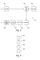
- Fig. 3 shows a measuring system according to another embodiment of the invention.
- the measuring system comprises a power supply 301, a processor or microcontroller (evaluation unit) 103, a scintillator 101, one or more photodiodes 102, a signal amplifier 302, comparators 104 and a current output or a fieldbus interface 303.
- a voltage multiplication can be provided.
- the scintillator 101 converts radioactive gamma radiation from a radiation source into flashes of light, which are converted into voltage pulses by the photodiode or photodiodes.
- the subsequent signal amplifier amplifies these voltage pulses.
- Comparators (for example, for each diode of one) then convert the voltage pulses into digital pulses counted by the processor 103.
- the process value ie the fill level in the tank or the density ratios in the tank) Tank
- the ionizing radiation in the container is more or less strongly absorbed or damped. This changes the pulse rate.
- the processor 103 determines the physical process value from the pulse rate.
- semiconductor devices have inherent noise, unwanted pulses, in particular avalanche photodiodes, can occur, so-called dark pulses.
- the active area of the semiconductor diodes is smaller than in photomultipliers.
- the measurement result can be improved. This increases the active area and at the same time suppresses the inherent noise, since the self-noise is not coherent with several diodes.
- the measurement pulses are very coherent if they are due to the same ionizing event.
- the output pulses of the diodes are first converted into digital signals before plausibility checks, such. For example, a "two out of three decision" that separates noise signals from the measurement pulses.
- Fig. 4 shows a flowchart of a method in which ionizing radiation is converted into electromagnetic radiation in step 401.
- the electromagnetic radiation is then converted by means of a photodiode into a voltage pulse.
- an assessment is made as to whether the resulting signal is the result of an ionizing event or noise.
- the then as valid measurement signals identified signals used to determine the level or density of the medium.
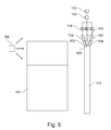
- Fig. 5 shows a measuring system according to another embodiment of the invention, in which not a directional radioactive radiator (as in Fig. 1 ), but a radiation source 106 is used which radiates in several directions and thus radiates through a large part of the container 107.
- a plurality of photodiodes 102, 113, 114 are coupled to the front side (that is to say at the upper side and / or the lower side). These can be connected by means of light guides 502, 503, 504 to the scintillator.
- the optical fibers split the resulting light flashes so that each photodiode can receive and detect part of it.
- the light guides can be made of plastic, glass or scintillator material. Any other material containing the second electromagnetic radiation, e.g. Light, can guide is suitable for this. A direct coupling of the photodiode to the scintillator or an air gap is suitable for this purpose.
- One or more comparators 104 detect the signals of the photodiodes and generate voltage pulses.
- at least one comparator is used per photodiode.
- a summation device 105 can sum up the voltage pulses of the comparators and pass the information on to the evaluation unit 103 if a minimum number of comparators have delivered a signal at the same time and the event is therefore due to a measurement signal and not to a noise signal from the photodiode.
Description
Die Erfindung betrifft die radiometrische Füllstands- oder Dichtemessung. Insbesondere betrifft die Erfindung ein radiometrisches Füllstandsmesssystem und ein radiometrisches Dichtemesssystem zur Bestimmung eines Füllstands oder einer Dichte eines Mediums sowie ein Verfahren zur radiometrischen Bestimmung eines Füllstands, für die Grenzstandmessung, einer Dichte eines Mediums oder für die Dursatzmessung an Förderbändern bzw. Förderschnecken.The invention relates to the radiometric fill level or density measurement. In particular, the invention relates to a radiometric level measurement system and a radiometric density measurement system for determining a level or a density of a medium and a method for the radiometric determination of a level, for the level measurement, a density of a medium or for measuring the duration of conveyor belts or screw conveyors.
In heutigen radiometrischen Messsystemen werden sog. Photomultiplier verwendet, die die von einem Szintillator erzeugten Lichtblitze detektieren und in ein elektrisches Signal umwandeln. Solche Photomultiplier benötigen eine aufwändige Spannungserzeugung. Außerdem ist der Platzbedarf relativ groß.In today's radiometric measuring systems so-called photomultipliers are used, which detect the light flashes generated by a scintillator and convert them into an electrical signal. Such photomultipliers require a complex voltage generation. In addition, the space requirement is relatively large.
Die
Es ist eine Aufgabe der Erfindung, ein verbessertes radiometrisches Messsystem für die Füllstandsmessung oder für die Dichtemessung zu schaffen.It is an object of the invention to provide an improved radiometric measurement system for level measurement or for density measurement.
Es sind ein radiometrisches Füllstands- oder Dichtemesssystem zur Bestimmung eines Füllstands oder einer Dichte eines Mediums sowie ein Verfahren zur radiometrischen Bestimmung eines Füllstands oder einer Dichte des Mediums gemäß den Merkmalen der unabhängigen Ansprüche angegeben. Weiterbildungen der Erfindung ergeben sich aus den Unteransprüchen.It is a radiometric level or density measurement system for determining a level or a density of a medium and a method for the radiometric determination of a level or a density of the medium specified according to the features of the independent claims. Further developments of the invention will become apparent from the dependent claims.
Die beschriebenen Ausführungsbeispiele betreffen gleichermaßen das Messsystem und das Verfahren. In anderen Worten lassen sich Merkmale, die im Folgenden im Hinblick auf das Messsystem beschrieben werden, auch in dem Verfahren implementieren, und umgekehrt.The described embodiments equally relate to the measuring system and the method. In other words, features that are described below with regard to the measuring system can also be implemented in the method, and vice versa.
Gemäß der Erfindung ist ein radiometrisches Füllstands- oder Dichtemesssystem zur Bestimmung eines Füllstands oder einer Dichte eines Mediums in einem Tank angegeben, wobei das Messsystem einen Umwandler, eine Photodiode und eine Auswerteeinheit aufweist. Der Umwandler dient dem zumindest teilweisen Umwandeln von ionisierender erster Strahlung, die das Medium durchstrahlt, in elektromagnetische zweite Strahlung. Die Photodiode dient dem zumindest teilweisen Umwandeln der zweiten Strahlung in ein elektrisches Signal z. B. ein Spannungssignal und die Auswerteeinheit dient der Bestimmung des Füllstands oder der Dichte des Mediums auf Basis einer Anzahl von erzeugten Spannungspulsen bzw. Spannungssignalen.According to the invention, a radiometric level or density measuring system for determining a level or a density of a medium in a tank is provided, wherein the measuring system comprises a converter, a photodiode and an evaluation unit. The converter serves to at least partially convert ionizing first radiation which transits the medium into electromagnetic second radiation. The photodiode serves to at least partially convert the second radiation into an electrical signal z. B. a voltage signal and the evaluation unit is used to determine the level or the density of the medium based on a number of generated voltage pulses or voltage signals.
In anderen Worten werden die von dem Umwandler ausgegebenen elektromagnetischen Signale (zweite Strahlung) zumindest teilweise von der Photodiode detektiert. Die Photodiode wandelt diese elektromagnetischen Signale in entsprechende Spannungssignale um, die dann gezählt werden können. Vor dem Zählen können miteinander korrespondierende Signale (die also auf demselben Ereignis beruhen) aufsummiert werden.In other words, the electromagnetic signals (second radiation) output by the converter are at least partially detected by the photodiode. The photodiode converts these electromagnetic signals into corresponding voltage signals, which can then be counted. Before counting, signals corresponding to one another (that is, based on the same event) can be summed up.
Ein Vorteil der Verwendung von Photodioden liegt darin, dass sie klein sind, preiswert herzustellen sind sowie einfach anzusteuern sind. Die Kombination mehrerer Photodioden erlaubt es, Dunkelpulse der Photodioden zu unterdrücken sowie die Empfindlichkeit des Systems zu erhöhen.An advantage of using photodiodes is that they are small, inexpensive to manufacture, and easy to drive. The combination of several photodiodes makes it possible to suppress dark pulses of the photodiodes and to increase the sensitivity of the system.
Unter dem zumindest teilweisen Umwandeln der ionisierenden Strahlung ist zu verstehen, dass nicht sämtliche Strahlung, die von der radioaktiven Quelle ausgesendet wird und den Tank durchläuft, umgewandelt werden muss. Es genügt, wenn lediglich ein Bruchteil dieser Strahlung umgewandelt wird. Ebendieses gilt auch für die Umwandlung der Strahlung durch die Photodiode, da die Photodiode bzw. der Photodiodenarray gegebenenfalls nicht sämtliche Strahlung vom Umwandler detektiert weil z.B. ein Teil dieser Strahlung an den Photodioden vorbeiläuft.By at least partially converting the ionizing radiation, it is to be understood that not all radiation emitted by the radioactive source and passing through the tank must be converted. It is sufficient if only a fraction of this radiation is converted. The same applies to the conversion of the radiation by the photodiode, since the photodiode or the photodiode array may not detect all the radiation from the converter because e.g. a portion of this radiation passes the photodiodes.
Gemäß einem weiteren Ausführungsbeispiel der Erfindung handelt es sich bei der Photodiode um eine Lawinenphotodiode (Avalanche Photodiode, APD).According to a further exemplary embodiment of the invention, the photodiode is an avalanche photodiode (avalanche photodiode, APD).
Statt beispielsweise eines Photomultipliers, der auf Röhrentechnologie beruht, wird eine Photodiode auf Halbleiterbasis verwendet. Diese ist kleiner und einfacher anzusteuern als ein Photomultiplier. Von Vorteil sind Avalanche Photodioden, da diese eine sehr hohe Empfindlichkeit aufweisen.Instead of, for example, a photomultiplier based on tube technology, a semiconductor-based photodiode is used. This is smaller and easier to control than a photomultiplier. Advantageous are avalanche photodiodes, as they have a very high sensitivity.
Gemäß einem weiteren Ausführungsbeispiel der Erfindung ist der Umwandler als Szintillationszähler oder Szintillator ausgeführt, der die auftreffende ionisierende Strahlung in Lichtblitze umwandelt.According to a further embodiment of the invention, the converter is designed as a scintillation counter or scintillator, which converts the incident ionizing radiation into flashes of light.
Gemäß einem weiteren Ausführungsbeispiel der Erfindung weist das Messsystem weiterhin einen Komparator zum Umwandeln des Spannungspulses aus der Photodiode in ein digitales Signal auf.According to a further embodiment of the invention, the measuring system further comprises a comparator for converting the voltage pulse from the photodiode into a digital signal.
Gemäß einem weiteren Ausführungsbeispiel der Erfindung ist die Auswerteeinheit zum Zählen der digitalen Signale, die von dem Komparator stammen, oder der Spannungspulse ausgeführt.According to a further exemplary embodiment of the invention, the evaluation unit is designed to count the digital signals originating from the comparator or the voltage pulses.
Gemäß der Erfindung weist das Messsystem eine Summationseinrichtung zum Aufsummieren von digitalen Signalen auf, die zur selben Zeit entstanden sind (also auf dem selben Ereignis im Szintillator beruhen und somit miteinander korrespondieren). Die Summationseinrichtung gibt dann ein korrespondierendes Summensignal aus. Die Auswerteeinheit dient in diesem Fall zum Zählen nur derjenigen Summensignale, welche eine vorbestimmte Mindestanzahl an digitalen Signalen aufweisen. Die restlichen Summensignale werden nicht gezählt, sondern verworfen.According to the invention, the measuring system has a summing device for accumulating digital signals which have arisen at the same time (ie are based on the same event in the scintillator and thus correspond with one another). The summation device then outputs a corresponding sum signal. The evaluation unit is used in this case for counting only those sum signals having a predetermined minimum number of digital signals. The remaining sum signals are not counted, but discarded.
Auf diese Weise kann vermieden werden, dass Fehlmessungen das Endergebnis negativ beeinflussen. Vielmehr werden nur diejenigen Signale berücksichtigt, die zur selben Zeit entstanden sind und demnach auf mehrere Lichtblitze zurückzuführen sind, die durch das selbe Ereignis im Szintillator generiert wurden, also beispielsweise von dem selben Gamma-Quant erzeugt wurden. Dunkelpulse, die z.B. durch das thermische Eigenrauschen der Photodiode erzeugt werden, stammen von unterschiedlichen Ereignissen und sind daher nicht zeitgleich. Diese werden hierdurch wirksam unterdrückt.In this way it can be avoided that incorrect measurements negatively affect the final result. Rather, only those signals are taken into account that were created at the same time and are therefore attributable to several flashes of light that were generated by the same event in the scintillator, so for example, were generated by the same gamma quant. Dark pulses, e.g. are generated by the thermal noise inherent in the photodiode come from different events and are therefore not simultaneous. These are thereby effectively suppressed.
Gemäß einem alterntiven Ausführungsbeispiel der Erfindung ist die Summationseinrichtung zum Aufsummieren von Spannungspulsen, die zur selben Zeit entstanden sind, und zur Ausgabe eines korrespondierenden Summensignals ausgeführt, wobei die Auswerteeinheit zum Zählen nur derjenigen Summensignale ausgeführt ist, welche eine vorbestimmte Mindestimpulsstärke aufweisen. Die restlichen Summensignale werden wieder verworfen.According to an alternative embodiment of the invention, the summation means is for accumulating voltage pulses which have arisen at the same time and for outputting a corresponding sum signal executed, wherein the evaluation unit is designed to count only those sum signals having a predetermined minimum pulse strength. The remaining sum signals are discarded again.
Gemäß der Erfindung ist ein Verfahren zur radiometrischen Bestimmung eines Füllstands oder einer Dichte eines Mediums angegeben, bei dem ionisierende erste Strahlung, die das Medium durchstrahlt, zumindest teilweise in elektromagnetische zweite Strahlung, z.B. Licht, umgewandelt wird. Diese zweite Strahlung wird zumindest teilweise in einen Spannungspuls mit Hilfe einer Photodiode umgewandelt. Danach erfolgt die Bestimmung des Füllstands oder der Dichte des Mediums auf Basis einer detektierten Anzahl an erzeugten Spannungspulsen.According to the invention, there is provided a method of radiometric determination of a level or density of a medium in which ionizing first radiation which transmits the medium is at least partially transformed into electromagnetic second radiation, e.g. Light, being transformed. This second radiation is at least partially converted into a voltage pulse by means of a photodiode. Thereafter, the determination of the level or the density of the medium is based on a detected number of generated voltage pulses.
Vor der Bestimmung des Füllstands oder der Dichte können die erzeugten Spannungspulse in digitale Signale umgewandelt werden, die daraufhin gezählt werden.Prior to determining the level or density, the generated voltage pulses may be converted to digital signals which are then counted.
Insbesondere können, wie bereits oben beschrieben, die digitalen Signale oder die Spannungspulse, die zur selben Zeit entstanden sind, aufsummiert werden. Das korrespondierende Summensignal wird nur dann für die Bestimmung des Messwerts verwendet, wenn es eine Mindestbedingung erfüllt. Zur Entscheidung, ob die Mindestbedingung erfüllt ist, kann ein Filter vorgesehen sein, der nur ausreichend starke Signale passieren lässt. Im Falle der Aufsummierung der digitalen Signale handelt es sich bei der Mindestbedingung darum, dass das Summensignal eine bestimmte Mindestzahl an digitalen Signalen aufweist, die miteinander addiert wurden. Im Falle der Aufsummierung der Spannungspulse handelt es sich bei der Mindestbedingung darum, dass der resultierende Gesamtimpuls eine Mindestimpulsstärke bzw. Mindestamplitude aufweist, also aus einer ausreichenden Anzahl an einzelnen Pulsen besteht.In particular, as already described above, the digital signals or the voltage pulses which have arisen at the same time can be summed up. The corresponding sum signal is only used for the determination of the measured value if it fulfills a minimum condition. To decide whether the minimum condition is met, a filter can be provided, which allows only pass sufficiently strong signals. In the case of summing the digital signals, the minimum condition is that the sum signal has a certain minimum number of digital signals added together. In the case of the summation of the voltage pulses, the minimum condition is that the resulting total pulse has a minimum pulse strength or minimum amplitude, that is to say consists of a sufficient number of individual pulses.
Im Folgenden werden mit Verweis auf die Figuren Ausführungsbeispiele der Erfindung beschrieben.In the following, embodiments of the invention will be described with reference to the figures.
-
Fig. 1 zeigt eine Darstellung eines Messsystems gemäß einem Ausführungsbeispiel der Erfindung.Fig. 1 shows a representation of a measuring system according to an embodiment of the invention. -
Fig. 2 zeigt eine Darstellung eines Messsystems gemäß einem weiteren Ausführungsbeispiel der Erfindung.Fig. 2 shows a representation of a measuring system according to another embodiment of the invention. -
Fig. 3 zeigt eine Darstellung eines Messsystems gemäß einem weiteren Ausführungsbeispiel der Erfindung.Fig. 3 shows a representation of a measuring system according to another embodiment of the invention. -
Fig. 4 zeigt ein Flussdiagramm eines Verfahrens gemäß einem Ausführungsbeispiel der Erfindung.Fig. 4 shows a flowchart of a method according to an embodiment of the invention. -
Fig. 5 zeigt eine Darstellung eines Messsystems gemäß einem weiteren Ausführungsbeispiel der Erfindung.Fig. 5 shows a representation of a measuring system according to another embodiment of the invention.
Die Darstellungen in den Figuren sind schematisch und nicht maßstäblich.The illustrations in the figures are schematic and not to scale.
In der folgenden Figurenbeschreibung werden für die gleichen oder ähnlichen Elemente die gleichen Bezugsziffern verwendet.In the following description of the figures, the same reference numerals are used for the same or similar elements.
Bei der radioaktiven Quelle handelt es sich beispielsweise um einen Gamma-Strahler. Die von der Quelle 106 erzeugte radioaktive bzw. ionisierende Strahlung 109 wird in Richtung eines Behälters oder Tanks 107 ausgestrahlt. Der Behälter 107 enthält ein Füllgut 108, beispielsweise in Form einer Flüssigkeit, eines Feststoffes oder eines Gases. Je nach Füllstand oder Dichte des Füllguts 108 wird die ionisierende Strahlung 109 beim Durchstrahlen des Behälters 107 mehr oder weniger stark gedämpft. Die auf der anderen Seite des Behälters heraustretende (Rest) Strahlung 110 trifft auf den Szintillationszähler 101.The radioactive source is, for example, a gamma emitter. The radioactive or
Hierbei ist zu bemerken, dass es sich bei der radioaktiven Quelle 106 auch um einen Alpha- oder einen Beta-Strahler handeln kann.It should be noted that the
Die ionisierende Strahlung bzw. das ionisierende Teilchen, das auf den Szintillator 101 trifft, erzeugt Lichtblitze 111, 112. Ein Gammaquant kann gleichzeitig hunderte bis tausende Photonen erzeugen, die zeitgleich emittiert werden und schussendlich als ein Ereignis registriert werden. Diese Lichtblitze (bzw. das Ereignis) werden von den Photodioden 102, 113, 114 aufgenommen und in entsprechende Spannungspulse umgewandelt, die miteinander korrelieren.The ionizing radiation or ionizing particle striking the
Die beiden Spannungspulse, die durch die Lichtblitze 111, 112 entstehen, werden in der Summationseinrichtung 105 aufsummiert und im Komparator 104 in ein digitales Signal umgewandelt, das dann, insofern das digitale Signal auf eine Mindestanzahl an einzelnen Spannungspulsen zurückzuführen ist, zur Bestimmung des Füllstandes oder der Dichte des Mediums durch die Auswerteeinheit 103 verwendet wird.The two voltage pulses which are produced by the flashes of
Die vom Szintillator 101 erzeugten Lichtblitze werden von dem Diodenarray 102, 113, 114, 201 bis 204, der flächig ausgeführt sein kann, zumindest teilweise aufgenommen und in entsprechende Spannungspulse umgewandelt. Sämtliche Spannungspulse werden danach im Komparator 104 digitalisiert. Korrespondierende digitale Signale werden anschließend in der Einrichtung 105 aufsummiert und als Summensignal an die Auswerteeinheit 103 weitergegeben.The light flashes generated by the
Auch kann eine Spannungsvervielfachung vorgesehen sein.Also, a voltage multiplication can be provided.
Der Szintillator 101 wandelt radioaktive Gamma-Strahlung einer Strahlungsquelle in Lichtblitze um, die von der oder den Photodioden in Spannungspulse gewandelt werden. Der anschließende Signalverstärker verstärkt diese Spannungspulse. Komparatoren (beispielsweise für jede Diode einer) wandeln die Spannungspulse dann in digitale Pulse um, die vom Prozessor 103 gezählt werden. Abhängig von dem Prozesswert (also dem Füllstand im Tank oder den Dichteverhältnissen im Tank) wird die ionisierende Strahlung im Behälter mehr oder weniger stark absorbiert bzw. gedämpft. Damit ändert sich die Pulsrate.The
Der Prozessor 103 bestimmt aus der Pulsrate den physikalischen Prozesswert.The
Da Halbleiterbausteine Eigenrauschen besitzen, kann es insbesondere bei Lawinenphotodioden zu ungewollten Pulsen kommen, sog. Dunkelpulse. Die aktive Fläche der Halbleiterdioden ist kleiner als bei Photomultipliern.
Verwendet man nun aber mehrerer Photodioden parallel (als Array), kann das Messergebnis verbessert werden. Hierdurch wird die aktive Fläche vergrößert und gleichzeitig das Eigenrauschen unterdrückt, da das Eigenrauschen bei mehreren Dioden nicht kohärent ist. Die Messpulse sind aber sehr wohl kohärent, wenn sie auf das selbe ionisierende Ereignis zurückzuführen sind.Since semiconductor devices have inherent noise, unwanted pulses, in particular avalanche photodiodes, can occur, so-called dark pulses. The active area of the semiconductor diodes is smaller than in photomultipliers.
However, if one uses several photodiodes in parallel (as an array), the measurement result can be improved. This increases the active area and at the same time suppresses the inherent noise, since the self-noise is not coherent with several diodes. However, the measurement pulses are very coherent if they are due to the same ionizing event.
Werden nun die Ausgangspulse der Dioden summiert, ergeben kohärente Messpulse größere Ausgangspulse als die nicht kohärenten Rauschsignale. Auf diese Weise können die Messsignale, die auf einem ionisierenden Ereignis beruhen, von denjenigen Messsignalen, die auf Rauschen beruhen, getrennt werden.Now, when the output pulses of the diodes are summed up, coherent measuring pulses produce larger output pulses than the non-coherent noise signals. In this way, the measurement signals that are based on an ionizing event can be separated from those measurement signals that are based on noise.
Auch ist es möglich, dass die Ausgangspulse der Dioden zuerst in digitale Signale gewandelt werden, bevor Plausibilitätsprüfungen, wie z. B. eine "zwei aus drei Entscheidung", die Rauschsignale von den Messpulsen trennen.It is also possible that the output pulses of the diodes are first converted into digital signals before plausibility checks, such. For example, a "two out of three decision" that separates noise signals from the measurement pulses.
Es findet also keine vertikal auflösende Messung statt, sondern es wird die im Szintillator entstehende Lichtintensität gemessen. Aus der gemessenen Intensität, die mit der Anzahl an Ereignissen (Lichtblitzen) korrespondiert, kann auf die Füllhöhe oder die Dichte des Mediums im Behälter geschlossen werden.So there is no vertical resolution measurement instead, but it is measured in the scintillator resulting light intensity. From the measured intensity, which corresponds to the number of events (flashes of light), it is possible to deduce the filling level or the density of the medium in the container.
Die Lichtleiter können aus Kunststoff, Glas oder aus Szintillatormaterial bestehen. Jedes andere Material, das die zweite elektromagnetische Strahlung, z.B. Licht, leiten kann ist hierfür geeignet. Auch eine direkte Kopplung der Photodiode an den Szintillator oder ein Luftspalt ist hierfür geeignet.The light guides can be made of plastic, glass or scintillator material. Any other material containing the second electromagnetic radiation, e.g. Light, can guide is suitable for this. A direct coupling of the photodiode to the scintillator or an air gap is suitable for this purpose.
Ein oder mehrere Komparatoren 104 detektieren die Signale der Photodioden und erzeugen Spannungspulse. Vorzugsweise wird pro Photodiode mindestens ein Komparator verwendet. Eine Summationseinrichtung 105 kann die Spannungspulse der Komparatoren aufsummieren und die Information an die Auswerteeinheit 103 weitergeben, wenn eine Mindestanzahl an Komparatoren gleichzeitig ein Signal abgegeben haben und das Ereignis daher auf ein Messsignal und nicht auf ein Rauschsignal der Photodiode zurückzuführen ist.One or
Ergänzend ist darauf hingewiesen, dass "umfassend" und "aufweisend" keine anderen Elemente oder Schritte ausschließt und "eine" oder "ein" keine Vielzahl ausschließt. Ferner sei darauf hingewiesen, dass Merkmale oder Schritte, die mit Verweis auf eines der obigen Ausführungsbeispiele beschrieben worden sind, auch in Kombination mit anderen Merkmalen oder Schritten anderer oben beschriebener Ausführungsbeispiele verwendet werden können. Bezugszeichen in den Ansprüchen sind nicht als Einschränkung anzusehen.In addition, it should be noted that "comprising" and "having" does not exclude other elements or steps, and "a" or "an" does not exclude a plurality. It should also be appreciated that features or steps described with reference to any of the above embodiments may also be used in combination with other features or steps of other embodiments described above. Reference signs in the claims are not to be considered as limiting.
Claims (8)
- A radiometric level or density measurement system for determining a level or a density of a medium, wherein the measurement system (100) features:a converter (101) for at least partially converting ionizing first radiation that penetrates the medium into electromagnetic second radiation;multiple photodiodes (102, 113, 114) for at least partially converting the second radiation from the converter (101) into voltage pulses;an evaluation unit (103) for determining the level or the density of the medium based on a number of generated voltage pulses;a summation device (105) for summing up digital signals, that were created at the same time or voltage pulses that were created at the same time, and for outputting a corresponding sum signal;wherein the evaluation unit (103) is designed for counting only the sum signals, with a predetermined minimum number of digital signals or with a predetermined minimum pulse intensity;wherein the remaining sum signals are discarded.
- The measurement system of claim 1,
wherein the photodiode is an avalanche photodiode. - The measurement system of one of the preceding claims,
wherein the measurement system features a plurality of photodiodes, that are arranged in the form of an array. - The measurement system of one of the preceding claims,
wherein the converter (101) is realized in the form of a scintillator. - The measurement system of one of the preceding claims, furthermore featuring:a comparator (104) for converting the voltage pulses into digital signals.
- The measurement system of one of the preceding claims,
wherein the evaluation unit (103) is designed for counting the digital signals originating from the comparator or the voltage pulses. - A method for radiometrically determining a level or a density of a medium, wherein said method features the following steps:at least partially converting ionizing first radiation, that penetrates the medium into electromagnetic second radiation through a converter (101);at least partially converting the second radiation from the converter (101) into voltage pulses with the aid of multiple photodiodes (102, 113,114);converting of the voltage pulses into digital signals and summing up of digital signals that were created at the same time or summing up of voltage pulses that were created at the same time and outputting of a corresponding sum signal;wherein only the sum signals with a predetermined minimum number of digital signals or with a predetermined minimum pulse intensity are counted;discarding the remaining sum signals;determining the level or the density of the medium based on the sum signals with a predetermined minimum number of digital signals or with a predetermined minimum pulse intensity are counted.
- The method of claim 7, furthermore featuring the following step:counting the digital signals or the voltage pulses.
Priority Applications (3)
| Application Number | Priority Date | Filing Date | Title |
|---|---|---|---|
| EP08170957.8A EP2194362B1 (en) | 2008-12-08 | 2008-12-08 | Radiometrical level or density measurement |
| CN200910253639.XA CN101750132B (en) | 2008-12-08 | 2009-12-07 | Radiometrical level or density measurement |
| US12/632,324 US8466417B2 (en) | 2008-12-08 | 2009-12-07 | Radiometric level or density measurement |
Applications Claiming Priority (1)
| Application Number | Priority Date | Filing Date | Title |
|---|---|---|---|
| EP08170957.8A EP2194362B1 (en) | 2008-12-08 | 2008-12-08 | Radiometrical level or density measurement |
Publications (2)
| Publication Number | Publication Date |
|---|---|
| EP2194362A1 EP2194362A1 (en) | 2010-06-09 |
| EP2194362B1 true EP2194362B1 (en) | 2016-07-27 |
Family
ID=40568735
Family Applications (1)
| Application Number | Title | Priority Date | Filing Date |
|---|---|---|---|
| EP08170957.8A Active EP2194362B1 (en) | 2008-12-08 | 2008-12-08 | Radiometrical level or density measurement |
Country Status (3)
| Country | Link |
|---|---|
| US (1) | US8466417B2 (en) |
| EP (1) | EP2194362B1 (en) |
| CN (1) | CN101750132B (en) |
Families Citing this family (8)
| Publication number | Priority date | Publication date | Assignee | Title |
|---|---|---|---|---|
| GB201114151D0 (en) * | 2011-08-17 | 2011-10-05 | Johnson Matthey Plc | Density and level measurement apparatus |
| DE102013114617A1 (en) * | 2013-12-20 | 2015-06-25 | Endress + Hauser Gmbh + Co. Kg | Radiometric instrument for performing measurements in potentially explosive atmospheres |
| DE102014101373A1 (en) | 2014-02-04 | 2015-08-06 | Vega Grieshaber Kg | Radiometric measuring system and method for operating a radiometric measuring system |
| US9983304B2 (en) * | 2015-02-20 | 2018-05-29 | Northrop Grumman Systems Corporation | Delta-sigma digital radiometric system |
| EP3064910B1 (en) * | 2015-03-05 | 2020-05-06 | Berthold Technologies GmbH & Co. KG | Radiometric detector for detecting a variable |
| EP3093628B1 (en) * | 2015-05-13 | 2020-05-27 | VEGA Grieshaber KG | Aging compensation and temperature compensation of a photomultiplier in a radiometric measuring device with scintillator assembly |
| EP3196607B1 (en) | 2016-01-25 | 2020-03-04 | Berthold Technologies GmbH & Co. KG | Radiometric process measurement system |
| EP3349047B1 (en) * | 2017-01-13 | 2020-12-23 | Berthold Technologies GmbH & Co. KG | Module system for a radiometric measuring device |
Citations (3)
| Publication number | Priority date | Publication date | Assignee | Title |
|---|---|---|---|---|
| US5218202A (en) * | 1991-04-29 | 1993-06-08 | Laboratorium Prof. Dr. Rudolf Berthold Gmbh & Co. | Method for automatic drift stabilization in radiation measurement with a detector |
| DE4233278A1 (en) * | 1992-10-02 | 1994-04-07 | Endress Hauser Gmbh Co | Process for the suppression of external radiation influences in radioactive measurement processes |
| DE10048559A1 (en) * | 2000-09-30 | 2002-04-11 | Endress Hauser Gmbh Co | Density and fill level determination apparatus for has analysis unit, which determines energy spectrum of secondary radiation, and control and evaluation unit, which carries out drift stabilization |
Family Cites Families (9)
| Publication number | Priority date | Publication date | Assignee | Title |
|---|---|---|---|---|
| US3501632A (en) | 1964-06-04 | 1970-03-17 | Rimvydas A Kaminskas | Penetrating radiation system for detecting the amount of liquid in a tank |
| US5270547A (en) | 1992-05-07 | 1993-12-14 | Independent Scintillation Imaging Systems (Isis) Inc. | Scintillation camera valid event discrimination |
| FR2755815B1 (en) | 1996-11-08 | 1998-12-18 | Commissariat Energie Atomique | DEVICE AND METHOD FOR DETERMINING THE PRESUMED POSITION OF AN EVENT IN RELATION TO A SET OF PHOTODETECTORS, AND APPLICATION TO GAMMA-CAMERAS |
| US6100532A (en) | 1997-03-14 | 2000-08-08 | Triumf | Detector for gamma rays |
| DE10043629A1 (en) | 2000-09-01 | 2002-03-14 | Endress Hauser Gmbh Co | Device for determining and / or monitoring the density and / or the filling level of a filling material in a container |
| DE10144764C2 (en) | 2001-09-11 | 2003-06-26 | Forschungszentrum Juelich Gmbh | Method for reading out measurement signals from multi-channel photomultipliers and circuit therefor |
| DE102004007680A1 (en) | 2004-02-16 | 2005-09-01 | Endress + Hauser Gmbh + Co. Kg | Radiometric measuring device |
| WO2006018766A2 (en) | 2004-08-13 | 2006-02-23 | Koninklijke Philips Electronics, N.V. | Timing calibration for a tof-pet scanner |
| DE102006048266A1 (en) | 2006-10-12 | 2008-04-17 | Berthold Technologies Gmbh & Co. Kg | Apparatus for measuring ionizing radiation |
-
2008
- 2008-12-08 EP EP08170957.8A patent/EP2194362B1/en active Active
-
2009
- 2009-12-07 US US12/632,324 patent/US8466417B2/en active Active
- 2009-12-07 CN CN200910253639.XA patent/CN101750132B/en active Active
Patent Citations (3)
| Publication number | Priority date | Publication date | Assignee | Title |
|---|---|---|---|---|
| US5218202A (en) * | 1991-04-29 | 1993-06-08 | Laboratorium Prof. Dr. Rudolf Berthold Gmbh & Co. | Method for automatic drift stabilization in radiation measurement with a detector |
| DE4233278A1 (en) * | 1992-10-02 | 1994-04-07 | Endress Hauser Gmbh Co | Process for the suppression of external radiation influences in radioactive measurement processes |
| DE10048559A1 (en) * | 2000-09-30 | 2002-04-11 | Endress Hauser Gmbh Co | Density and fill level determination apparatus for has analysis unit, which determines energy spectrum of secondary radiation, and control and evaluation unit, which carries out drift stabilization |
Also Published As
| Publication number | Publication date |
|---|---|
| US8466417B2 (en) | 2013-06-18 |
| EP2194362A1 (en) | 2010-06-09 |
| CN101750132B (en) | 2014-02-26 |
| CN101750132A (en) | 2010-06-23 |
| US20100140480A1 (en) | 2010-06-10 |
Similar Documents
| Publication | Publication Date | Title |
|---|---|---|
| EP2194362B1 (en) | Radiometrical level or density measurement | |
| EP1569012B1 (en) | Method for the detection of ionizing radiation | |
| EP1314006B1 (en) | Device for determining and/or monitoring the level of a filling material in a container | |
| DE10352012B4 (en) | Detector module for CT and / or PET and / or SPECT tomography | |
| DE102008033960A1 (en) | Radiation detector module i.e. X-ray radiation detector module, for e.g. X-ray-computer tomography-device, has photo-detection unit connected with scintillation elements, detecting light, and including silicon-photomultiplier | |
| DE112006001456T5 (en) | Methods and systems for medical imaging | |
| DE102009002816A1 (en) | Radiometric measuring device | |
| EP2378312B1 (en) | Diagnosis of radiometric detectors | |
| DE112015004713T5 (en) | Photon counting detector | |
| DE112012005517T5 (en) | Methods and apparatus for measuring the effective atomic number of an object | |
| DE102007034982B4 (en) | Method for operating a clocked, counting X-ray detector | |
| DE102017217538A1 (en) | Radiometric two-wire gauge for level or density measurement | |
| DE102016222298A1 (en) | Radiometric level measurement | |
| DE102011077397B4 (en) | X-ray imaging device with coincidence circuits in detector units | |
| EP2963451A1 (en) | Dose measuring device for measuring the eye lens dose | |
| DE4223773A1 (en) | Method for differentiation and simultaneous or separate measurement of single and multi-electron events in an optoelectronic detector | |
| DE202015103673U1 (en) | Signal sampling in a radiometric measuring system | |
| EP3561459B1 (en) | Device and method for measuring a medium fill level or density by the help of muons | |
| DE102011006393A1 (en) | Method for obtaining x-rays based spectrum information for pixels in raster image, involves providing x-ray detectors with multiple pixel elements, where each pixel corresponds to raster image | |
| WO2016083021A1 (en) | Scintillation detector with a high count rate | |
| DE102019122115B4 (en) | Detector unit for a scintillation counter, radiometric measuring device with such a detector unit, method for operating such a detector unit and computer program code | |
| Gruber | Studies of SiPM photosensors for time-of-flight detectors within PANDA at FAIR | |
| WO2017063772A1 (en) | Method, device and use of the device for the detection of neutrons, and reading and processing unit | |
| DE102010043944B3 (en) | Method for minimizing the orientation dependence of automatic drift compensation of a scintillation counter | |
| DE102005033533A1 (en) | Method and device for examining a test object by means of invasive radiation |
Legal Events
| Date | Code | Title | Description |
|---|---|---|---|
| PUAI | Public reference made under article 153(3) epc to a published international application that has entered the european phase |
Free format text: ORIGINAL CODE: 0009012 |
|
| AK | Designated contracting states |
Kind code of ref document: A1 Designated state(s): AT BE BG CH CY CZ DE DK EE ES FI FR GB GR HR HU IE IS IT LI LT LU LV MC MT NL NO PL PT RO SE SI SK TR |
|
| AX | Request for extension of the european patent |
Extension state: AL BA MK RS |
|
| 17P | Request for examination filed |
Effective date: 20100909 |
|
| AKX | Designation fees paid |
Designated state(s): AT BE BG CH CY CZ DE DK EE ES FI FR GB GR HR HU IE IS IT LI LT LU LV MC MT NL NO PL PT RO SE SI SK TR |
|
| 17Q | First examination report despatched |
Effective date: 20141117 |
|
| TPAC | Observations filed by third parties |
Free format text: ORIGINAL CODE: EPIDOSNTIPA |
|
| TPAC | Observations filed by third parties |
Free format text: ORIGINAL CODE: EPIDOSNTIPA |
|
| TPAC | Observations filed by third parties |
Free format text: ORIGINAL CODE: EPIDOSNTIPA |
|
| TPAC | Observations filed by third parties |
Free format text: ORIGINAL CODE: EPIDOSNTIPA |
|
| GRAP | Despatch of communication of intention to grant a patent |
Free format text: ORIGINAL CODE: EPIDOSNIGR1 |
|
| GRAP | Despatch of communication of intention to grant a patent |
Free format text: ORIGINAL CODE: EPIDOSNIGR1 |
|
| INTG | Intention to grant announced |
Effective date: 20160223 |
|
| INTG | Intention to grant announced |
Effective date: 20160315 |
|
| GRAS | Grant fee paid |
Free format text: ORIGINAL CODE: EPIDOSNIGR3 |
|
| GRAA | (expected) grant |
Free format text: ORIGINAL CODE: 0009210 |
|
| AK | Designated contracting states |
Kind code of ref document: B1 Designated state(s): AT BE BG CH CY CZ DE DK EE ES FI FR GB GR HR HU IE IS IT LI LT LU LV MC MT NL NO PL PT RO SE SI SK TR |
|
| REG | Reference to a national code |
Ref country code: GB Ref legal event code: FG4D Free format text: NOT ENGLISH |
|
| REG | Reference to a national code |
Ref country code: CH Ref legal event code: EP |
|
| REG | Reference to a national code |
Ref country code: AT Ref legal event code: REF Ref document number: 816168 Country of ref document: AT Kind code of ref document: T Effective date: 20160815 |
|
| REG | Reference to a national code |
Ref country code: IE Ref legal event code: FG4D Free format text: LANGUAGE OF EP DOCUMENT: GERMAN |
|
| REG | Reference to a national code |
Ref country code: DE Ref legal event code: R096 Ref document number: 502008014430 Country of ref document: DE |
|
| REG | Reference to a national code |
Ref country code: LT Ref legal event code: MG4D |
|
| REG | Reference to a national code |
Ref country code: NL Ref legal event code: MP Effective date: 20160727 |
|
| REG | Reference to a national code |
Ref country code: NO Ref legal event code: T2 Effective date: 20160727 |
|
| PG25 | Lapsed in a contracting state [announced via postgrant information from national office to epo] |
Ref country code: LT Free format text: LAPSE BECAUSE OF FAILURE TO SUBMIT A TRANSLATION OF THE DESCRIPTION OR TO PAY THE FEE WITHIN THE PRESCRIBED TIME-LIMIT Effective date: 20160727 Ref country code: FI Free format text: LAPSE BECAUSE OF FAILURE TO SUBMIT A TRANSLATION OF THE DESCRIPTION OR TO PAY THE FEE WITHIN THE PRESCRIBED TIME-LIMIT Effective date: 20160727 Ref country code: IT Free format text: LAPSE BECAUSE OF FAILURE TO SUBMIT A TRANSLATION OF THE DESCRIPTION OR TO PAY THE FEE WITHIN THE PRESCRIBED TIME-LIMIT Effective date: 20160727 Ref country code: HR Free format text: LAPSE BECAUSE OF FAILURE TO SUBMIT A TRANSLATION OF THE DESCRIPTION OR TO PAY THE FEE WITHIN THE PRESCRIBED TIME-LIMIT Effective date: 20160727 Ref country code: IS Free format text: LAPSE BECAUSE OF FAILURE TO SUBMIT A TRANSLATION OF THE DESCRIPTION OR TO PAY THE FEE WITHIN THE PRESCRIBED TIME-LIMIT Effective date: 20161127 Ref country code: NL Free format text: LAPSE BECAUSE OF FAILURE TO SUBMIT A TRANSLATION OF THE DESCRIPTION OR TO PAY THE FEE WITHIN THE PRESCRIBED TIME-LIMIT Effective date: 20160727 |
|
| PG25 | Lapsed in a contracting state [announced via postgrant information from national office to epo] |
Ref country code: ES Free format text: LAPSE BECAUSE OF FAILURE TO SUBMIT A TRANSLATION OF THE DESCRIPTION OR TO PAY THE FEE WITHIN THE PRESCRIBED TIME-LIMIT Effective date: 20160727 Ref country code: GR Free format text: LAPSE BECAUSE OF FAILURE TO SUBMIT A TRANSLATION OF THE DESCRIPTION OR TO PAY THE FEE WITHIN THE PRESCRIBED TIME-LIMIT Effective date: 20161028 Ref country code: PT Free format text: LAPSE BECAUSE OF FAILURE TO SUBMIT A TRANSLATION OF THE DESCRIPTION OR TO PAY THE FEE WITHIN THE PRESCRIBED TIME-LIMIT Effective date: 20161128 Ref country code: PL Free format text: LAPSE BECAUSE OF FAILURE TO SUBMIT A TRANSLATION OF THE DESCRIPTION OR TO PAY THE FEE WITHIN THE PRESCRIBED TIME-LIMIT Effective date: 20160727 Ref country code: SE Free format text: LAPSE BECAUSE OF FAILURE TO SUBMIT A TRANSLATION OF THE DESCRIPTION OR TO PAY THE FEE WITHIN THE PRESCRIBED TIME-LIMIT Effective date: 20160727 Ref country code: LV Free format text: LAPSE BECAUSE OF FAILURE TO SUBMIT A TRANSLATION OF THE DESCRIPTION OR TO PAY THE FEE WITHIN THE PRESCRIBED TIME-LIMIT Effective date: 20160727 |
|
| PG25 | Lapsed in a contracting state [announced via postgrant information from national office to epo] |
Ref country code: RO Free format text: LAPSE BECAUSE OF FAILURE TO SUBMIT A TRANSLATION OF THE DESCRIPTION OR TO PAY THE FEE WITHIN THE PRESCRIBED TIME-LIMIT Effective date: 20160727 Ref country code: EE Free format text: LAPSE BECAUSE OF FAILURE TO SUBMIT A TRANSLATION OF THE DESCRIPTION OR TO PAY THE FEE WITHIN THE PRESCRIBED TIME-LIMIT Effective date: 20160727 |
|
| REG | Reference to a national code |
Ref country code: DE Ref legal event code: R097 Ref document number: 502008014430 Country of ref document: DE |
|
| PG25 | Lapsed in a contracting state [announced via postgrant information from national office to epo] |
Ref country code: BG Free format text: LAPSE BECAUSE OF FAILURE TO SUBMIT A TRANSLATION OF THE DESCRIPTION OR TO PAY THE FEE WITHIN THE PRESCRIBED TIME-LIMIT Effective date: 20161027 Ref country code: DK Free format text: LAPSE BECAUSE OF FAILURE TO SUBMIT A TRANSLATION OF THE DESCRIPTION OR TO PAY THE FEE WITHIN THE PRESCRIBED TIME-LIMIT Effective date: 20160727 Ref country code: SK Free format text: LAPSE BECAUSE OF FAILURE TO SUBMIT A TRANSLATION OF THE DESCRIPTION OR TO PAY THE FEE WITHIN THE PRESCRIBED TIME-LIMIT Effective date: 20160727 Ref country code: CZ Free format text: LAPSE BECAUSE OF FAILURE TO SUBMIT A TRANSLATION OF THE DESCRIPTION OR TO PAY THE FEE WITHIN THE PRESCRIBED TIME-LIMIT Effective date: 20160727 Ref country code: BE Free format text: LAPSE BECAUSE OF NON-PAYMENT OF DUE FEES Effective date: 20161231 |
|
| PLBE | No opposition filed within time limit |
Free format text: ORIGINAL CODE: 0009261 |
|
| STAA | Information on the status of an ep patent application or granted ep patent |
Free format text: STATUS: NO OPPOSITION FILED WITHIN TIME LIMIT |
|
| 26N | No opposition filed |
Effective date: 20170502 |
|
| REG | Reference to a national code |
Ref country code: CH Ref legal event code: PL |
|
| PG25 | Lapsed in a contracting state [announced via postgrant information from national office to epo] |
Ref country code: SI Free format text: LAPSE BECAUSE OF FAILURE TO SUBMIT A TRANSLATION OF THE DESCRIPTION OR TO PAY THE FEE WITHIN THE PRESCRIBED TIME-LIMIT Effective date: 20160727 |
|
| PG25 | Lapsed in a contracting state [announced via postgrant information from national office to epo] |
Ref country code: MC Free format text: LAPSE BECAUSE OF FAILURE TO SUBMIT A TRANSLATION OF THE DESCRIPTION OR TO PAY THE FEE WITHIN THE PRESCRIBED TIME-LIMIT Effective date: 20160727 |
|
| REG | Reference to a national code |
Ref country code: FR Ref legal event code: ST Effective date: 20170831 |
|
| REG | Reference to a national code |
Ref country code: IE Ref legal event code: MM4A |
|
| PG25 | Lapsed in a contracting state [announced via postgrant information from national office to epo] |
Ref country code: LU Free format text: LAPSE BECAUSE OF NON-PAYMENT OF DUE FEES Effective date: 20161208 Ref country code: CH Free format text: LAPSE BECAUSE OF NON-PAYMENT OF DUE FEES Effective date: 20161231 Ref country code: LI Free format text: LAPSE BECAUSE OF NON-PAYMENT OF DUE FEES Effective date: 20161231 Ref country code: FR Free format text: LAPSE BECAUSE OF NON-PAYMENT OF DUE FEES Effective date: 20170102 |
|
| PG25 | Lapsed in a contracting state [announced via postgrant information from national office to epo] |
Ref country code: IE Free format text: LAPSE BECAUSE OF NON-PAYMENT OF DUE FEES Effective date: 20161208 |
|
| REG | Reference to a national code |
Ref country code: BE Ref legal event code: MM Effective date: 20161231 |
|
| REG | Reference to a national code |
Ref country code: AT Ref legal event code: MM01 Ref document number: 816168 Country of ref document: AT Kind code of ref document: T Effective date: 20161208 |
|
| PG25 | Lapsed in a contracting state [announced via postgrant information from national office to epo] |
Ref country code: CY Free format text: LAPSE BECAUSE OF FAILURE TO SUBMIT A TRANSLATION OF THE DESCRIPTION OR TO PAY THE FEE WITHIN THE PRESCRIBED TIME-LIMIT Effective date: 20160727 Ref country code: HU Free format text: LAPSE BECAUSE OF FAILURE TO SUBMIT A TRANSLATION OF THE DESCRIPTION OR TO PAY THE FEE WITHIN THE PRESCRIBED TIME-LIMIT; INVALID AB INITIO Effective date: 20081208 Ref country code: AT Free format text: LAPSE BECAUSE OF NON-PAYMENT OF DUE FEES Effective date: 20161208 |
|
| PG25 | Lapsed in a contracting state [announced via postgrant information from national office to epo] |
Ref country code: TR Free format text: LAPSE BECAUSE OF FAILURE TO SUBMIT A TRANSLATION OF THE DESCRIPTION OR TO PAY THE FEE WITHIN THE PRESCRIBED TIME-LIMIT Effective date: 20160727 |
|
| PG25 | Lapsed in a contracting state [announced via postgrant information from national office to epo] |
Ref country code: MT Free format text: LAPSE BECAUSE OF FAILURE TO SUBMIT A TRANSLATION OF THE DESCRIPTION OR TO PAY THE FEE WITHIN THE PRESCRIBED TIME-LIMIT Effective date: 20160727 |
|
| P01 | Opt-out of the competence of the unified patent court (upc) registered |
Effective date: 20230524 |
|
| PGFP | Annual fee paid to national office [announced via postgrant information from national office to epo] |
Ref country code: GB Payment date: 20231220 Year of fee payment: 16 |
|
| PGFP | Annual fee paid to national office [announced via postgrant information from national office to epo] |
Ref country code: NO Payment date: 20231218 Year of fee payment: 16 Ref country code: DE Payment date: 20231214 Year of fee payment: 16 |