EP2194287A1 - A method of controlling a friction clutch in a motor-vehicle transmission - Google Patents
A method of controlling a friction clutch in a motor-vehicle transmission Download PDFInfo
- Publication number
- EP2194287A1 EP2194287A1 EP08425772A EP08425772A EP2194287A1 EP 2194287 A1 EP2194287 A1 EP 2194287A1 EP 08425772 A EP08425772 A EP 08425772A EP 08425772 A EP08425772 A EP 08425772A EP 2194287 A1 EP2194287 A1 EP 2194287A1
- Authority
- EP
- European Patent Office
- Prior art keywords
- torque
- clutch
- characteristic
- transmitted
- curve
- Prior art date
- Legal status (The legal status is an assumption and is not a legal conclusion. Google has not performed a legal analysis and makes no representation as to the accuracy of the status listed.)
- Granted
Links
Images


Classifications
-
- F—MECHANICAL ENGINEERING; LIGHTING; HEATING; WEAPONS; BLASTING
- F16—ENGINEERING ELEMENTS AND UNITS; GENERAL MEASURES FOR PRODUCING AND MAINTAINING EFFECTIVE FUNCTIONING OF MACHINES OR INSTALLATIONS; THERMAL INSULATION IN GENERAL
- F16D—COUPLINGS FOR TRANSMITTING ROTATION; CLUTCHES; BRAKES
- F16D48/00—External control of clutches
- F16D48/06—Control by electric or electronic means, e.g. of fluid pressure
-
- F—MECHANICAL ENGINEERING; LIGHTING; HEATING; WEAPONS; BLASTING
- F16—ENGINEERING ELEMENTS AND UNITS; GENERAL MEASURES FOR PRODUCING AND MAINTAINING EFFECTIVE FUNCTIONING OF MACHINES OR INSTALLATIONS; THERMAL INSULATION IN GENERAL
- F16D—COUPLINGS FOR TRANSMITTING ROTATION; CLUTCHES; BRAKES
- F16D2500/00—External control of clutches by electric or electronic means
- F16D2500/30—Signal inputs
- F16D2500/302—Signal inputs from the actuator
- F16D2500/3026—Stroke
-
- F—MECHANICAL ENGINEERING; LIGHTING; HEATING; WEAPONS; BLASTING
- F16—ENGINEERING ELEMENTS AND UNITS; GENERAL MEASURES FOR PRODUCING AND MAINTAINING EFFECTIVE FUNCTIONING OF MACHINES OR INSTALLATIONS; THERMAL INSULATION IN GENERAL
- F16D—COUPLINGS FOR TRANSMITTING ROTATION; CLUTCHES; BRAKES
- F16D2500/00—External control of clutches by electric or electronic means
- F16D2500/30—Signal inputs
- F16D2500/304—Signal inputs from the clutch
- F16D2500/30404—Clutch temperature
-
- F—MECHANICAL ENGINEERING; LIGHTING; HEATING; WEAPONS; BLASTING
- F16—ENGINEERING ELEMENTS AND UNITS; GENERAL MEASURES FOR PRODUCING AND MAINTAINING EFFECTIVE FUNCTIONING OF MACHINES OR INSTALLATIONS; THERMAL INSULATION IN GENERAL
- F16D—COUPLINGS FOR TRANSMITTING ROTATION; CLUTCHES; BRAKES
- F16D2500/00—External control of clutches by electric or electronic means
- F16D2500/30—Signal inputs
- F16D2500/304—Signal inputs from the clutch
- F16D2500/3042—Signal inputs from the clutch from the output shaft
- F16D2500/30421—Torque of the output shaft
- F16D2500/30425—Estimation of the transmitted clutch torque, e.g. applying dynamic torque balance equation
-
- F—MECHANICAL ENGINEERING; LIGHTING; HEATING; WEAPONS; BLASTING
- F16—ENGINEERING ELEMENTS AND UNITS; GENERAL MEASURES FOR PRODUCING AND MAINTAINING EFFECTIVE FUNCTIONING OF MACHINES OR INSTALLATIONS; THERMAL INSULATION IN GENERAL
- F16D—COUPLINGS FOR TRANSMITTING ROTATION; CLUTCHES; BRAKES
- F16D2500/00—External control of clutches by electric or electronic means
- F16D2500/30—Signal inputs
- F16D2500/306—Signal inputs from the engine
- F16D2500/3065—Torque of the engine
-
- F—MECHANICAL ENGINEERING; LIGHTING; HEATING; WEAPONS; BLASTING
- F16—ENGINEERING ELEMENTS AND UNITS; GENERAL MEASURES FOR PRODUCING AND MAINTAINING EFFECTIVE FUNCTIONING OF MACHINES OR INSTALLATIONS; THERMAL INSULATION IN GENERAL
- F16D—COUPLINGS FOR TRANSMITTING ROTATION; CLUTCHES; BRAKES
- F16D2500/00—External control of clutches by electric or electronic means
- F16D2500/30—Signal inputs
- F16D2500/306—Signal inputs from the engine
- F16D2500/3067—Speed of the engine
- F16D2500/3068—Speed change of rate of the engine
-
- F—MECHANICAL ENGINEERING; LIGHTING; HEATING; WEAPONS; BLASTING
- F16—ENGINEERING ELEMENTS AND UNITS; GENERAL MEASURES FOR PRODUCING AND MAINTAINING EFFECTIVE FUNCTIONING OF MACHINES OR INSTALLATIONS; THERMAL INSULATION IN GENERAL
- F16D—COUPLINGS FOR TRANSMITTING ROTATION; CLUTCHES; BRAKES
- F16D2500/00—External control of clutches by electric or electronic means
- F16D2500/30—Signal inputs
- F16D2500/308—Signal inputs from the transmission
- F16D2500/3081—Signal inputs from the transmission from the input shaft
- F16D2500/30814—Torque of the input shaft
-
- F—MECHANICAL ENGINEERING; LIGHTING; HEATING; WEAPONS; BLASTING
- F16—ENGINEERING ELEMENTS AND UNITS; GENERAL MEASURES FOR PRODUCING AND MAINTAINING EFFECTIVE FUNCTIONING OF MACHINES OR INSTALLATIONS; THERMAL INSULATION IN GENERAL
- F16D—COUPLINGS FOR TRANSMITTING ROTATION; CLUTCHES; BRAKES
- F16D2500/00—External control of clutches by electric or electronic means
- F16D2500/50—Problem to be solved by the control system
- F16D2500/502—Relating the clutch
- F16D2500/50236—Adaptations of the clutch characteristics, e.g. curve clutch capacity torque - clutch actuator displacement
-
- F—MECHANICAL ENGINEERING; LIGHTING; HEATING; WEAPONS; BLASTING
- F16—ENGINEERING ELEMENTS AND UNITS; GENERAL MEASURES FOR PRODUCING AND MAINTAINING EFFECTIVE FUNCTIONING OF MACHINES OR INSTALLATIONS; THERMAL INSULATION IN GENERAL
- F16D—COUPLINGS FOR TRANSMITTING ROTATION; CLUTCHES; BRAKES
- F16D2500/00—External control of clutches by electric or electronic means
- F16D2500/50—Problem to be solved by the control system
- F16D2500/502—Relating the clutch
- F16D2500/50245—Calibration or recalibration of the clutch touch-point
- F16D2500/50266—Way of detection
- F16D2500/50281—Transmitted torque
-
- F—MECHANICAL ENGINEERING; LIGHTING; HEATING; WEAPONS; BLASTING
- F16—ENGINEERING ELEMENTS AND UNITS; GENERAL MEASURES FOR PRODUCING AND MAINTAINING EFFECTIVE FUNCTIONING OF MACHINES OR INSTALLATIONS; THERMAL INSULATION IN GENERAL
- F16D—COUPLINGS FOR TRANSMITTING ROTATION; CLUTCHES; BRAKES
- F16D2500/00—External control of clutches by electric or electronic means
- F16D2500/70—Details about the implementation of the control system
- F16D2500/702—Look-up tables
- F16D2500/70252—Clutch torque
- F16D2500/70264—Stroke
-
- F—MECHANICAL ENGINEERING; LIGHTING; HEATING; WEAPONS; BLASTING
- F16—ENGINEERING ELEMENTS AND UNITS; GENERAL MEASURES FOR PRODUCING AND MAINTAINING EFFECTIVE FUNCTIONING OF MACHINES OR INSTALLATIONS; THERMAL INSULATION IN GENERAL
- F16D—COUPLINGS FOR TRANSMITTING ROTATION; CLUTCHES; BRAKES
- F16D2500/00—External control of clutches by electric or electronic means
- F16D2500/70—Details about the implementation of the control system
- F16D2500/706—Strategy of control
- F16D2500/70605—Adaptive correction; Modifying control system parameters, e.g. gains, constants, look-up tables
-
- F—MECHANICAL ENGINEERING; LIGHTING; HEATING; WEAPONS; BLASTING
- F16—ENGINEERING ELEMENTS AND UNITS; GENERAL MEASURES FOR PRODUCING AND MAINTAINING EFFECTIVE FUNCTIONING OF MACHINES OR INSTALLATIONS; THERMAL INSULATION IN GENERAL
- F16D—COUPLINGS FOR TRANSMITTING ROTATION; CLUTCHES; BRAKES
- F16D2500/00—External control of clutches by electric or electronic means
- F16D2500/70—Details about the implementation of the control system
- F16D2500/706—Strategy of control
- F16D2500/70673—Statistical calculations
- F16D2500/70684—Statistical calculations using regressions
Definitions
- the present invention relates to a method of controlling a friction clutch in a transmission of a motor vehicle provided with an internal combustion engine.
- control method comprising the steps of:
- Controlled friction clutches are being used more and more in motor-vehicle transmissions, for example, in so-called “dual clutch” transmissions.
- the movable portion of a clutch of this type is brought, by means of suitable conventional actuators, to an operative position (relative to the stationary portion) in which the clutch transmits the desired nominal torque.
- An object of the present invention is to propose a control method which overcomes this disadvantage.
- a method of the type specified above characterized in that, upon the occurrence of predetermined operative conditions, the value of the torque transmitted by the clutch is estimated, by means of an algorithm, as a function of the detected instantaneous values of the torque delivered and of the angular velocity of the shaft of the engine, and the corresponding instantaneous position, or estimate position, of the clutch is detected, and the previously stored curve or characteristic is then modified in accordance with predetermined procedures in dependence on the difference between the estimated value of the torque transmitted and that value of the torque transmitted which corresponds to the estimate position according to the previously stored curve or characteristic.
- the torque transmitted by the friction clutch is estimated during a normal operating cycle of the associated actuator, in particular during the pick-up and gear-changing stages.
- the stored transmissibility curve or characteristic comprises a plurality of contiguous linear sections corresponding to respective adjacent ranges or bands of values of the position of the clutch.
- the torque transmitted values that are associated with the ends of the range or band in which the estimate position is included are modified in accordance with predetermined procedures.
- the torque values that are associated with the ends are modified in dependence on the difference between the estimated value of the torque transmitted and that value which is associated with the same position of the clutch according to the previously stored characteristic or curve.
- a motor-vehicle internal combustion engine indicated E, has a shaft S which can be connected to a primary shaft PS of a transmission TR by means of a controlled friction clutch FC.
- the clutch FC is of known type and the position x of its movable portion is controlled by means of an associated actuator EA which may be, for example, an electromagnetically-operated actuator.
- the actuator EA is driven by an electronic control system, generally indicated ECS.
- ECS electronice control system
- This system comprises an electronic processing and control unit ECU which receives signals or data from a plurality of sensors and detectors.
- ECU electronic processing and control unit
- the following are connected to the electronic unit ECU:
- sensors or detectors are also connected to the unit ECU for supplying thereto signals or data on the basis of which the unit ECU can detect the occurrence of predetermined operative conditions such as those which will be described further below.
- the clutch transfers to the shaft PS of the transmission TR a variable fraction of the torque T E developed by the engine E, according to the degree of closure of the clutch FC.
- the torque transmitted to the shaft PS of the transmission TR by means of the clutch FC is indicated T in Figure 1 as well as in the following drawings.
- the torque T transmitted is thus a function of the position x (of the movable portion) of the clutch FC.
- a memory M ( Figure 1 ) is associated with the electronic unit ECU; a curve or characteristic representative of the torque T transmitted by the clutch FC as a function of the position x is stored in the memory M.
- the curve or characteristic of transmissibility (torque transmitted as a function of position) has a non-linear shape.
- the transmissibility curve or characteristic of a clutch of this type is approximated by means of a plurality of contiguous linear sections corresponding to respective adjacent ranges or bands of clutch position values, as shown in Figure 2 .
- the position X may correspond precisely to the actual position x of the movable portion of the clutch or may be a "standardized" position obtained, for example, by dividing the values of the position x by the value x M (maximum of the position x), possibly multiplied by a scaling factor, for example, of 1000.
- the transmissibility curve or characteristic is, for example, that indicated A.
- the transmissibility curve or characteristic of the same clutch has a linearized trace of the type shown by the curve B of Figure 2 .
- the transmissibility curve or characteristic of the clutch has an intermediate trace between the curves A and B, for example, the trace of the linearized curve indicated C in Figure 2 .
- the band Z1 extends between the value 0 (origin point) and a value X1 of the position X
- the band Z2 extends between the value X1 and a value X2 of the position X
- the band Z3 extends between the value X2 and a value X3 of the position X.
- an intermediate transmissibility curve or characteristic between those corresponding to the "new" clutch condition and the "maximum wear” condition, for example, the transmissibility curve of the type indicated C in Figure 2 is stored in the memory M of the electronic unit ECU.
- the unit ECU arranges from time to time for the transmissibility curve or characteristic to be checked and possibly updated in the manner which will now be described.
- the unit ECU arranges to estimate, in predetermined operative conditions, the value TC of the torque T instantaneously transmitted by the clutch FC as a function of the detected instantaneous values of the torque T E delivered by the engine E and of the angular velocity ⁇ E of the engine shaft S, at the same time detecting the corresponding value XC of the corresponding instantaneous position of the clutch, hereinafter defined as the "estimate position".
- TC T E - J E ⁇ d ⁇ ⁇ E dt
- J E is the moment of inertia of the shaft S of the engine E and t is the time.
- the estimated value TC and the associated value XC of the friction clutch position identify a point indicated PC in the plane T, X in Figure 3 .
- the transmissibility curve or characteristic stored in the memory M of the electronic unit ECU at the moment at which the value TC corresponding to the position XC of the friction clutch is estimated is indicated C O in Figure 3 .
- the electronic unit ECU does not proceed with any updating of the transmissibility curve or characteristic stored in the memory M.
- the unit ECU arranges to modify the transmissibility curve or characteristic stored in the memory M in the manner which will now be described.
- the graphs of Figure 3 relate to a situation in which the estimated value TC of the torque T transmitted by the clutch and the associated clutch position value XC identify a point PC which lies within the range or band Z1; in other words, the estimate position XC falls within the range of positions which extends from 0 to X1, the width of which range is indicated B in Figure 3 .
- the electronic unit ECU is arranged to modify the transmissibility curve or characteristic stored in the memory M by modifying first of all the section of that curve corresponding to the band Z1, and then the sections of that curve or characteristic which fall within the bands Z2 and Z3.
- the modified transmissibility curve or characteristic must nevertheless pass through the origin reference point T, X so that, essentially, the unit ECU arranges to modify the inclination or slope of the first linear section of the transmissibility curve or characteristic.
- This in fact translates into a modification of the torque value that is associated with the upper end X1 of the first range or band Z1; this torque value is modified by a quantity corresponding to the torque difference ⁇ T (between the estimated value TC and the value of the torque T transmitted which, according to the previously stored curve or characteristic C O , corresponds to the estimate position XC), multiplied by a factor which is a function of the estimate position XC.
- the first linear section of the previously stored transmissibility curve or characteristic C O is thus replaced by the line joining the origin point 0 and the point T1 N , X1.
- the linear sections of the transmissibility curve or characteristic subsequent to the first section are also modified by translation by the same quantity ⁇ T1.
- the curve or characteristic C N of Figure 3 is then stored in the memory M in place of the previously stored curve or characteristic C O .
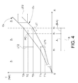
- the graphs of Figure 4 show the procedure for modifying the stored transmissibility curve or characteristic when the point PC estimated, that is, identified by the estimated value TC of torque transmitted and by the associated position (estimate position) XC lies within a range or band subsequent to the first range or band Z1, in particular, in the range or band Z2.
- the corresponding linear section of the stored transmissibility curve or characteristic is modified in a manner such that the transmitted torque values associated with the ends X1 and X2 of that range or band are modified by respective quantities ⁇ T1, ⁇ T2 which are predetermined in dependence on the torque difference ⁇ T between the estimated value TC and that torque value T which corresponds to the estimate position XC according to the previously stored transmissibility curve.
- the transmitted torque values associated with the ends of the range in which the estimate position XC lies are modified by respective quantities which depend on the torque difference ⁇ T and on the respective distances A, B - A of those ends from the estimate position XC.
- the linear section or sections of the transmissibility curve or characteristic subsequent to the range Z2 in which the estimate position (XC) lies are translated by a quantity equal to the modification ⁇ T2 of the transmitted torque value corresponding to the upper end X2 of the range Z2.
- the linear section of the transmissibility curve which precedes the range Z2 in which the estimate position XC lies is modified in a manner such that the torque value associated with the upper end X1 of the preceding range or band Z1 is modified by a quantity corresponding to the torque value modification ⁇ T1 for the lower end (X1) of the range Z2 in which the estimate position lies.
- the initial linear section of the new transmissibility curve C N is obtained by joining the origin reference point T,X to the initial point of the second linear section of the new transmissibility curve.
- the unit ECU arranges, if necessary, to modify the transmissibility curve stored by operating in the same way as described above with reference to the case in which the estimate point PC lies in the second range or band Z2.
- the updating of the transmissibility curve or characteristic stored in the memory M is enabled by the unit ECU only when predetermined operative conditions occur, for example, when the following conditions occur simultaneously:
- the above-described control method compensates for degradation and ageing of the friction clutch FC used and enables the performance of the control system to be ensured substantially throughout the useful life cycle of the component.
Abstract
Description
- The present invention relates to a method of controlling a friction clutch in a transmission of a motor vehicle provided with an internal combustion engine.
- More specifically, the subject of the invention is a control method comprising the steps of:
- storing a characteristic curve of torque transmitted by the friction clutch as a function of the position of the clutch,
- calculating a desired value of the torque to be transmitted by means of the clutch, and
- modifying the position of the clutch so as to bring it to the position to which the desired transmitted torque value corresponds according to the stored curve or characteristic.
- Controlled friction clutches are being used more and more in motor-vehicle transmissions, for example, in so-called "dual clutch" transmissions. In use, the movable portion of a clutch of this type is brought, by means of suitable conventional actuators, to an operative position (relative to the stationary portion) in which the clutch transmits the desired nominal torque.
- The curve or characteristic of torque transmitted/position of a clutch of this type inevitably varies over time owing to degradation and ageing phenomena and because of wear of the friction linings.
- Consequently, with the passage of time, the torque transmission that corresponds to a predetermined position (of the movable portion) of a clutch of this type is gradually reduced.
- An object of the present invention is to propose a control method which overcomes this disadvantage.
- This and other objects are achieved, according to the invention, by a method of the type specified above, characterized in that, upon the occurrence of predetermined operative conditions, the value of the torque transmitted by the clutch is estimated, by means of an algorithm, as a function of the detected instantaneous values of the torque delivered and of the angular velocity of the shaft of the engine, and the corresponding instantaneous position, or estimate position, of the clutch is detected, and the previously stored curve or characteristic is then modified in accordance with predetermined procedures in dependence on the difference between the estimated value of the torque transmitted and that value of the torque transmitted which corresponds to the estimate position according to the previously stored curve or characteristic.
- Typically, the torque transmitted by the friction clutch is estimated during a normal operating cycle of the associated actuator, in particular during the pick-up and gear-changing stages.
- In one embodiment, the stored transmissibility curve or characteristic comprises a plurality of contiguous linear sections corresponding to respective adjacent ranges or bands of values of the position of the clutch.
- During the implementation of the method, the torque transmitted values that are associated with the ends of the range or band in which the estimate position is included are modified in accordance with predetermined procedures.
- In particular, the torque values that are associated with the ends are modified in dependence on the difference between the estimated value of the torque transmitted and that value which is associated with the same position of the clutch according to the previously stored characteristic or curve.
- Further characteristics and advantages of the invention will become clear from the following detailed description which is given purely by way of non-limiting example with reference to the appended drawings, in which:
-
Figure 1 is a block diagram of a motor-vehicle transmission comprising a friction clutch controlled by the method according to the invention, -
Figure 2 is a graph which shows the linearized traces of the transmissibility curve or characteristic of a friction clutch, and -
Figures 3 and4 are two graphs which illustrate the procedure for updating a stored transmissibility curve or characteristic. - In
Figure 1 , a motor-vehicle internal combustion engine, indicated E, has a shaft S which can be connected to a primary shaft PS of a transmission TR by means of a controlled friction clutch FC. The clutch FC is of known type and the position x of its movable portion is controlled by means of an associated actuator EA which may be, for example, an electromagnetically-operated actuator. - The actuator EA is driven by an electronic control system, generally indicated ECS. This system comprises an electronic processing and control unit ECU which receives signals or data from a plurality of sensors and detectors. In particular, the following are connected to the electronic unit ECU:
- a detector D1 for supplying signals or data indicative of the value of the torque TE developed in the shaft S of the engine E,
- a detector D2, for example, of the phonic wheel type, for supplying signals or data indicative of the angular velocity ωE of the shaft S of the engine E,
- a detector D3 for supplying signals or data indicative of the position x of the movable portion of the clutch FC relative to the stationary portion, and
- a detector D4 for supplying signals or data indicative of the temperature TFC of the friction clutch FC.
- Further sensors or detectors, not shown in
Figure 1 , are also connected to the unit ECU for supplying thereto signals or data on the basis of which the unit ECU can detect the occurrence of predetermined operative conditions such as those which will be described further below. - In operation, the clutch transfers to the shaft PS of the transmission TR a variable fraction of the torque TE developed by the engine E, according to the degree of closure of the clutch FC. The torque transmitted to the shaft PS of the transmission TR by means of the clutch FC is indicated T in
Figure 1 as well as in the following drawings. - The torque T transmitted is thus a function of the position x (of the movable portion) of the clutch FC.
- A memory M (
Figure 1 ) is associated with the electronic unit ECU; a curve or characteristic representative of the torque T transmitted by the clutch FC as a function of the position x is stored in the memory M. - In general, for a typical friction clutch for automotive use, the curve or characteristic of transmissibility (torque transmitted as a function of position) has a non-linear shape.
- In the method according to the invention, the transmissibility curve or characteristic of a clutch of this type is approximated by means of a plurality of contiguous linear sections corresponding to respective adjacent ranges or bands of clutch position values, as shown in
Figure 2 . - In this drawing, the clutch position X is given on the abscissa and the torque T transmitted by the clutch is given on the ordinate.
- The position X may correspond precisely to the actual position x of the movable portion of the clutch or may be a "standardized" position obtained, for example, by dividing the values of the position x by the value xM (maximum of the position x), possibly multiplied by a scaling factor, for example, of 1000.
- With reference to
Figure 2 , for a "new" clutch (never used), the transmissibility curve or characteristic is, for example, that indicated A. - In conditions of maximum wear, the transmissibility curve or characteristic of the same clutch has a linearized trace of the type shown by the curve B of
Figure 2 . - In a generic intermediate condition between minimum (zero) wear and maximum wear, the transmissibility curve or characteristic of the clutch has an intermediate trace between the curves A and B, for example, the trace of the linearized curve indicated C in
Figure 2 . - The linearization of the transmissibility characteristics shown in
Figure 2 arranges for each curve or characteristic to comprise three contiguous linear sections A1-A3, B1-B3, C1-C3 in respective adjacent ranges or bands Z1-Z3 of values of the clutch position X. - In
Figure 2 , the band Z1 extends between the value 0 (origin point) and a value X1 of the position X, the band Z2 extends between the value X1 and a value X2 of the position X, and the band Z3 extends between the value X2 and a value X3 of the position X. - The
values 0, X1, X2 and X3 will also be referred to below as "ends" of the above-mentioned ranges of bands of clutch position values. - Initially, an intermediate transmissibility curve or characteristic between those corresponding to the "new" clutch condition and the "maximum wear" condition, for example, the transmissibility curve of the type indicated C in
Figure 2 , is stored in the memory M of the electronic unit ECU. - Subsequently, when the motor-vehicle is in use, the unit ECU arranges from time to time for the transmissibility curve or characteristic to be checked and possibly updated in the manner which will now be described.
- From time to time, the unit ECU arranges to estimate, in predetermined operative conditions, the value TC of the torque T instantaneously transmitted by the clutch FC as a function of the detected instantaneous values of the torque TE delivered by the engine E and of the angular velocity ωE of the engine shaft S, at the same time detecting the corresponding value XC of the corresponding instantaneous position of the clutch, hereinafter defined as the "estimate position".
- The value TC of the torque T transmitted by the clutch FC is estimated, for example, on the basis of the following equation:

where JE is the moment of inertia of the shaft S of the engine E and t is the time. - Alternatively, with a more "refined" approach, the value TC of the torque T transmitted by the clutch FC may be estimated on the basis of the following equation:

where f(TFC) is a predetermined function of the temperature TFC of the friction clutch FC. - The estimated value TC and the associated value XC of the friction clutch position identify a point indicated PC in the plane T, X in
Figure 3 . - The transmissibility curve or characteristic stored in the memory M of the electronic unit ECU at the moment at which the value TC corresponding to the position XC of the friction clutch is estimated is indicated CO in
Figure 3 . - If the point PC identified by the pair of values TC, XC lies on the curve or characteristic CO or within a neighbouring area of predetermined width, the electronic unit ECU does not proceed with any updating of the transmissibility curve or characteristic stored in the memory M.
- If, on the other hand, as in the example of
Figure 3 , the point PC lies considerably outside the curve CO, the unit ECU arranges to modify the transmissibility curve or characteristic stored in the memory M in the manner which will now be described. - The graphs of
Figure 3 relate to a situation in which the estimated value TC of the torque T transmitted by the clutch and the associated clutch position value XC identify a point PC which lies within the range or band Z1; in other words, the estimate position XC falls within the range of positions which extends from 0 to X1, the width of which range is indicated B inFigure 3 . - In a situation of this type, the electronic unit ECU is arranged to modify the transmissibility curve or characteristic stored in the memory M by modifying first of all the section of that curve corresponding to the band Z1, and then the sections of that curve or characteristic which fall within the bands Z2 and Z3.
- In the case to which
Figure 3 relates, in which the estimated point PC falls within band Z1, the modified transmissibility curve or characteristic must nevertheless pass through the origin reference point T, X so that, essentially, the unit ECU arranges to modify the inclination or slope of the first linear section of the transmissibility curve or characteristic. This in fact translates into a modification of the torque value that is associated with the upper end X1 of the first range or band Z1; this torque value is modified by a quantity corresponding to the torque difference ΔT (between the estimated value TC and the value of the torque T transmitted which, according to the previously stored curve or characteristic CO, corresponds to the estimate position XC), multiplied by a factor which is a function of the estimate position XC. - The following equation can easily be derived from
Figure 3 by simple geometrical considerations:
where: - T1N is the new torque transmitted value associated with the position X1,
- T1O is the old torque transmitted value associated with the position X1 according to the previously stored transmissibility characteristic,
- A is the width of the range XC - 0, and
- B = X1 - 0 is the width of the first range or band Z1.
- The first linear section of the previously stored transmissibility curve or characteristic CO is thus replaced by the line joining the
origin point 0 and the point T1N, X1. - As shown in
Figure 3 , the linear sections of the transmissibility curve or characteristic subsequent to the first section are also modified by translation by the same quantity ΔT1. - The curve or characteristic CN of
Figure 3 is then stored in the memory M in place of the previously stored curve or characteristic CO. - The graphs of
Figure 4 , on the other hand, show the procedure for modifying the stored transmissibility curve or characteristic when the point PC estimated, that is, identified by the estimated value TC of torque transmitted and by the associated position (estimate position) XC lies within a range or band subsequent to the first range or band Z1, in particular, in the range or band Z2. - In this case, the corresponding linear section of the stored transmissibility curve or characteristic is modified in a manner such that the transmitted torque values associated with the ends X1 and X2 of that range or band are modified by respective quantities ΔT1, ΔT2 which are predetermined in dependence on the torque difference ΔT between the estimated value TC and that torque value T which corresponds to the estimate position XC according to the previously stored transmissibility curve.
- By analogy with the symbols used in
Figure 3 , the distance between the estimate position XC and the lower end X1 of the band Z2 in which the position XC lies, and the width X2-X1 of the band Z2 are indicated A and B, respectively, inFigure 4 . - The electronic unit ECU is arranged to calculate the new torque transmitted values T1N and T2N that are associated with the positions X1 and X2 as functions of the values T1O and T2O that are associated with those positions according to the previously stored transmissibility curve or characteristic, on the basis of the following equations which can easily be derived from
Figure 4 on the basis of simple geometrical considerations:

- In summary, the transmitted torque values associated with the ends of the range in which the estimate position XC lies are modified by respective quantities which depend on the torque difference ΔT and on the respective distances A, B - A of those ends from the estimate position XC.
- Still with reference to the case of
Figure 4 , the linear section or sections of the transmissibility curve or characteristic subsequent to the range Z2 in which the estimate position (XC) lies are translated by a quantity equal to the modification ΔT2 of the transmitted torque value corresponding to the upper end X2 of the range Z2. - Again with reference to
Figure 4 , the linear section of the transmissibility curve which precedes the range Z2 in which the estimate position XC lies is modified in a manner such that the torque value associated with the upper end X1 of the preceding range or band Z1 is modified by a quantity corresponding to the torque value modification ΔT1 for the lower end (X1) of the range Z2 in which the estimate position lies. In other words, the initial linear section of the new transmissibility curve CN is obtained by joining the origin reference point T,X to the initial point of the second linear section of the new transmissibility curve. - If the estimate position XC at which the value TC of the torque transmitted by the clutch FC is estimated lies in the upper range or band Z3, the unit ECU arranges, if necessary, to modify the transmissibility curve stored by operating in the same way as described above with reference to the case in which the estimate point PC lies in the second range or band Z2.
- In any case, as already mentioned above, the updating of the transmissibility curve or characteristic stored in the memory M is enabled by the unit ECU only when predetermined operative conditions occur, for example, when the following conditions occur simultaneously:
- a pick-up stage is in progress;
- the torque TE produced by the engine E is within a predetermined range (for example, between 20 Nm and 450 Nm);
- the engine E has reached a predetermined minimum temperature (for example, greater than 75°C);
- the temperature TFC of the clutch FC is within a predetermined range (for example, between 70 and 200°C);
- the angular acceleration of the shaft S of the engine E is below a predetermined value (for example, 50 rad/s2);
- the slipping velocity of the clutch FC is above a threshold (for example, 150 rpm);
- the absolute value of the time derivative of the torque T transmitted by the clutch FC is less than or equal to a predetermined threshold value;
- the change in the relative position of the clutch FC is kept above a threshold for a predetermined period of time (for example, 10 ms).
- The above-described control method compensates for degradation and ageing of the friction clutch FC used and enables the performance of the control system to be ensured substantially throughout the useful life cycle of the component.
- Naturally, the principle of the invention remaining the same, the forms of embodiment and details of construction may be varied widely with respect to those described and illustrated purely by way of non-limiting example, without thereby departing from the scope of the invention as defined in the appended claims.
Claims (14)
- A method of controlling a friction clutch (FC) in a transmission (TR) of a motor vehicle provided with an internal combustion engine (E), the method comprising the steps of:- storing a curve or characteristic (CO) of torque (T) transmitted by the friction clutch (FC) as a function of the position (X) of the clutch,- calculating a desired value of the torque to be transmitted by means of the clutch (FC), and- modifying the position (X) of the clutch (FC) so as to bring it to the position (X) to which the desired transmitted torque value (T) corresponds according to the stored curve or characteristic (CO),the method being characterized in that:upon the occurrence of predetermined operative conditions, the value (TC) of the torque (T) transmitted by the clutch (FC) is estimated, by means of an algorithm, as a function of the detected instantaneous values of the torque delivered (TE) and of the angular velocity (ωE) of the shaft (S) of the engine (E), and the corresponding instantaneous position or estimate position (XC) of the clutch (FC) is detected, andthe previously stored curve or characteristic (CO) is then modified in accordance with predetermined procedures, in dependence on the difference (ΔT) between the estimated value (TC) of the torque (T) transmitted and that value of the torque (T) transmitted which corresponds to the estimate position (XC) according to the previously stored curve or characteristic (CO).
- A method according to Claim 1 in which the stored curve or characteristic comprises a plurality of contiguous linear sections (C1, C2, C3) corresponding to respective adjacent ranges or bands (Z1, Z2, Z3) of values of the position (X) of the clutch (FC).
- A method according to Claim 2 in which the torque values associated with the ends (0, X1; X1, X2; X2, X3) of the range or band (Z1; Z2; Z3) in which the estimate position (XC) is included are modified in accordance with predetermined procedures.
- A method according to Claim 3 in which the torque values associated with the ends (0, X1; X1, X2; X2, X3) are modified in dependence on the difference (ΔT) between the estimated value (TC) of the torque transmitted (T) and that value which is associated with the same position (XC) of the clutch (FC) according to the previously stored characteristic or curve (Co).
- A method according to Claim 4 in which, for the first range or band (Z1) starting from the origin (0), the modification of the curve or characteristic of torque transmitted (CO) is such that the modified curve or characteristic (CN) also comes from the origin (0).
- A method according to Claim 5 in which, when the estimate position (XC) lies within the first range or band (Z1), the corresponding first linear section of the stored curve or characteristic (CO) is modified in a manner such that the torque value (T1) that is associated with the upper end (X1) of the first range or band (Z1) is modified by a quantity corresponding to the difference in torque transmitted (ΔT) multiplied by a factor (B/A) which is a function of the estimate position (XC).
- A method according to Claim 6 in which the factor (B/A) is a function of the distance between the estimate position (XC) and the ends (0, X1) of the first range or band (Z1).
- A method according to Claim 7 in which the factor (B/A) is equal to the ratio between the width (B) of the first range or band (Z1) and the distance (A) between the estimate position (XC) and the origin (0).
- A method according to any one of Claims 6 to 8 in which the linear sections of the curve or characteristic subsequent to the first section are translated by the same above-mentioned quantity (ΔT).
- A method according to any one of Claims 4 to 9 in which, when the estimate position (XC) lies within a range subsequent to the first range (Z1), the corresponding linear section of the stored curve or characteristic is modified in a manner such that the torque transmitted values (T1, T2) that are associated with the ends (X1, X2) of the range (Z2) are modified by respective quantities (ΔT1; ΔT2) which are predetermined in dependence on the torque difference (ΔT) and the respective distances A; B - A) from the estimate position (XC).
- A method according to Claim 10 in which the linear sections of the stored curve or characteristic which are subsequent to the range (Z2) in which the estimate position (XC) lies are translated by a quantity (ΔT2) equal to the modification of the value of the torque transmitted (T2) at the upper end (X2) of the range (Z2).
- A method according to Claim 10 or Claim 11 in which the linear section of the stored curve or characteristic which precedes the range (Z2) in which the estimate position (XC) lies is modified in a manner such that the torque value that is associated with the upper end (X1) of the preceding range (Z1) is modified by a quantity (ΔT1) corresponding to the modification of the torque value for the lower end (X1) of the range (Z2) in which the estimate position (XC) lies.
- A method according to any one of the preceding claims in which the torque transmitted by the clutch (FC) is estimated by finding the difference between the detected engine torque (TE) and the product of the moment of inertia (JE) of the shaft (S) of the engine (E) and the angular acceleration (dωE/dt) of the shaft (S).
- A method according to Claim 13 in which the difference is multiplied by a factor (f(TFC)) which is a predetermined function of the detected temperature (TFC) of the clutch (FC).
Priority Applications (3)
| Application Number | Priority Date | Filing Date | Title |
|---|---|---|---|
| EP08425772.4A EP2194287B1 (en) | 2008-12-03 | 2008-12-03 | A method of controlling a friction clutch in a motor-vehicle transmission |
| US12/620,989 US8571767B2 (en) | 2008-12-03 | 2009-11-18 | Method of controlling a friction clutch in a motor-vehicle transmission |
| CN2009102536794A CN101749414B (en) | 2008-12-03 | 2009-12-02 | A method of controlling a friction clutch in a motor-vehicle transmission |
Applications Claiming Priority (1)
| Application Number | Priority Date | Filing Date | Title |
|---|---|---|---|
| EP08425772.4A EP2194287B1 (en) | 2008-12-03 | 2008-12-03 | A method of controlling a friction clutch in a motor-vehicle transmission |
Publications (2)
| Publication Number | Publication Date |
|---|---|
| EP2194287A1 true EP2194287A1 (en) | 2010-06-09 |
| EP2194287B1 EP2194287B1 (en) | 2013-05-29 |
Family
ID=40561847
Family Applications (1)
| Application Number | Title | Priority Date | Filing Date |
|---|---|---|---|
| EP08425772.4A Active EP2194287B1 (en) | 2008-12-03 | 2008-12-03 | A method of controlling a friction clutch in a motor-vehicle transmission |
Country Status (3)
| Country | Link |
|---|---|
| US (1) | US8571767B2 (en) |
| EP (1) | EP2194287B1 (en) |
| CN (1) | CN101749414B (en) |
Cited By (5)
| Publication number | Priority date | Publication date | Assignee | Title |
|---|---|---|---|---|
| FR2998346A1 (en) * | 2012-11-20 | 2014-05-23 | Peugeot Citroen Automobiles Sa | Method for conversion of instruction of torque to instruction of final position of actuator of clutch in car, involves adding position value of relocated nominal position and selected compensation value to obtain final position instruction |
| FR2998527A1 (en) * | 2012-11-28 | 2014-05-30 | Peugeot Citroen Automobiles Sa | METHOD AND DEVICE FOR ADAPTING THE NOMINAL CHARACTERISTIC OF A TORQUE TRANSMITTED BY A CLUTCH BASED ON ESTIMATED TORQUE ODDS |
| FR3030422A1 (en) * | 2014-12-22 | 2016-06-24 | Renault Sa | METHOD AND SYSTEM FOR CONTROLLING A MOTORIZED ACTUATED MECHANICAL CLUTCH |
| EP3101300A1 (en) * | 2015-06-01 | 2016-12-07 | Aisin Seiki Kabushiki Kaisha | Clutch characteristic learning apparatus |
| KR20180069602A (en) * | 2016-12-15 | 2018-06-25 | 현대자동차주식회사 | Method and device for calibrating engine clutch delivery torque of hybrid vehicle |
Families Citing this family (13)
| Publication number | Priority date | Publication date | Assignee | Title |
|---|---|---|---|---|
| JP5267043B2 (en) * | 2008-10-23 | 2013-08-21 | 株式会社ジェイテクト | Driving force distribution device and torque coupling control method |
| CN102129487B (en) * | 2010-11-18 | 2012-10-03 | 杭州高特数码技术有限公司 | Method for simulative generation of working condition curve of electric vehicle |
| US20140324309A1 (en) * | 2010-12-20 | 2014-10-30 | Volvo Lastvagnar Ab | Method and system for calibrating an estimated clutch characteristic curve |
| KR101786126B1 (en) * | 2012-10-26 | 2017-10-17 | 현대자동차주식회사 | Motor torque control method for electric vehicle with transmission |
| DE102013114959B4 (en) | 2013-01-07 | 2022-02-03 | GM Global Technology Operations LLC (n. d. Ges. d. Staates Delaware) | Upshift control of a dry dual clutch transmission |
| DE102013114958B4 (en) * | 2013-01-07 | 2023-12-28 | GM Global Technology Operations LLC (n. d. Gesetzen des Staates Delaware) | Start-up control for a vehicle with a dual clutch transmission |
| US8996266B2 (en) * | 2013-01-07 | 2015-03-31 | GM Global Technology Operations LLC | Dual clutch transmission vehicle launch control |
| US9140359B2 (en) * | 2013-01-07 | 2015-09-22 | GM Global Technology Operations LLC | Upshift control of a dry dual-clutch transmission |
| US9002606B1 (en) * | 2013-09-24 | 2015-04-07 | GM Global Technology Operations LLC | System and method for controlling a dry dual clutch transmission of a vehicle |
| KR101551008B1 (en) | 2013-12-17 | 2015-09-07 | 현대자동차주식회사 | Dry type clutch characteristic adjusting method for dct |
| KR101628519B1 (en) * | 2014-11-05 | 2016-06-09 | 현대자동차주식회사 | Clutch characteristic adjusting method for vehicle with dct |
| KR101628528B1 (en) * | 2014-11-17 | 2016-06-09 | 현대자동차주식회사 | Touch point adjusting method for dct |
| KR101776499B1 (en) | 2016-05-20 | 2017-09-20 | 현대자동차주식회사 | Clutch control method of hybrid vehicle |
Citations (5)
| Publication number | Priority date | Publication date | Assignee | Title |
|---|---|---|---|---|
| EP1411262A2 (en) * | 2002-10-18 | 2004-04-21 | Aisin Seiki Kabushiki Kaisha | Clutch control device |
| EP1418083A2 (en) * | 2002-11-11 | 2004-05-12 | LuK Lamellen und Kupplungsbau Beteiligungs KG | Method and device for the operation of a vehicle |
| EP1630442A1 (en) * | 2004-08-25 | 2006-03-01 | Aisin Seiki Kabushiki Kaisha | Clutch control device |
| EP1840401A1 (en) * | 2006-03-30 | 2007-10-03 | Industrial Technology Research Institute | Method for defining a touch point of a clutch and a torque characteristic curve relating thereto |
| DE102007015679A1 (en) * | 2007-03-31 | 2008-10-02 | Zf Friedrichshafen Ag | Method for controlling an automated friction clutch |
-
2008
- 2008-12-03 EP EP08425772.4A patent/EP2194287B1/en active Active
-
2009
- 2009-11-18 US US12/620,989 patent/US8571767B2/en active Active
- 2009-12-02 CN CN2009102536794A patent/CN101749414B/en active Active
Patent Citations (5)
| Publication number | Priority date | Publication date | Assignee | Title |
|---|---|---|---|---|
| EP1411262A2 (en) * | 2002-10-18 | 2004-04-21 | Aisin Seiki Kabushiki Kaisha | Clutch control device |
| EP1418083A2 (en) * | 2002-11-11 | 2004-05-12 | LuK Lamellen und Kupplungsbau Beteiligungs KG | Method and device for the operation of a vehicle |
| EP1630442A1 (en) * | 2004-08-25 | 2006-03-01 | Aisin Seiki Kabushiki Kaisha | Clutch control device |
| EP1840401A1 (en) * | 2006-03-30 | 2007-10-03 | Industrial Technology Research Institute | Method for defining a touch point of a clutch and a torque characteristic curve relating thereto |
| DE102007015679A1 (en) * | 2007-03-31 | 2008-10-02 | Zf Friedrichshafen Ag | Method for controlling an automated friction clutch |
Cited By (7)
| Publication number | Priority date | Publication date | Assignee | Title |
|---|---|---|---|---|
| FR2998346A1 (en) * | 2012-11-20 | 2014-05-23 | Peugeot Citroen Automobiles Sa | Method for conversion of instruction of torque to instruction of final position of actuator of clutch in car, involves adding position value of relocated nominal position and selected compensation value to obtain final position instruction |
| FR2998527A1 (en) * | 2012-11-28 | 2014-05-30 | Peugeot Citroen Automobiles Sa | METHOD AND DEVICE FOR ADAPTING THE NOMINAL CHARACTERISTIC OF A TORQUE TRANSMITTED BY A CLUTCH BASED ON ESTIMATED TORQUE ODDS |
| WO2014083253A1 (en) * | 2012-11-28 | 2014-06-05 | Peugeot Citroen Automobiles Sa | Method and device for adapting the nominal characteristic of a torque transmitted by a clutch as a function of estimated torque differences |
| FR3030422A1 (en) * | 2014-12-22 | 2016-06-24 | Renault Sa | METHOD AND SYSTEM FOR CONTROLLING A MOTORIZED ACTUATED MECHANICAL CLUTCH |
| EP3101300A1 (en) * | 2015-06-01 | 2016-12-07 | Aisin Seiki Kabushiki Kaisha | Clutch characteristic learning apparatus |
| KR20180069602A (en) * | 2016-12-15 | 2018-06-25 | 현대자동차주식회사 | Method and device for calibrating engine clutch delivery torque of hybrid vehicle |
| KR102383232B1 (en) | 2016-12-15 | 2022-04-05 | 현대자동차 주식회사 | Method and device for calibrating engine clutch delivery torque of hybrid vehicle |
Also Published As
| Publication number | Publication date |
|---|---|
| CN101749414A (en) | 2010-06-23 |
| EP2194287B1 (en) | 2013-05-29 |
| CN101749414B (en) | 2013-12-11 |
| US8571767B2 (en) | 2013-10-29 |
| US20100138121A1 (en) | 2010-06-03 |
Similar Documents
| Publication | Publication Date | Title |
|---|---|---|
| EP2194287B1 (en) | A method of controlling a friction clutch in a motor-vehicle transmission | |
| US8392083B2 (en) | Clutch contact points | |
| EP2655914B1 (en) | Method and system for calibrating an estimated clutch characteristic curve | |
| US8892322B2 (en) | Clutch parameters | |
| KR101629582B1 (en) | Method and apparatus for controlling transmission of vehicle | |
| US8897980B2 (en) | Method of estimating transmission torque of dry clutch of vehicle | |
| US20170138418A1 (en) | Method for learning clutch characteristic in dual clutch transmission vehicle | |
| US10974712B2 (en) | Vehicle and method for operating a clutch as a starter element | |
| US9822831B2 (en) | Method for learning touch point of dual clutch transmission | |
| US11828361B2 (en) | Method for determining a drag torque coefficient | |
| KR20140142665A (en) | Method for determining a wear of a clutch | |
| US9534645B2 (en) | Touch point correction method for double clutch transmission | |
| US8062181B2 (en) | Method and control device for adjusting a rotational speed of a shaft of a gear change transmission | |
| US20170043779A1 (en) | Control method of vehicle | |
| KR20130131478A (en) | Method and system for determination of a need for contact point adaptation | |
| US20020038747A1 (en) | Method of detecting the operating state of a friction clutch | |
| EP1416182B1 (en) | Clutch control device | |
| KR101583872B1 (en) | Estimating method for detecting abrasion of dry type clutch in vehicle | |
| JP2012062998A (en) | Lock-up clutch controller of automatic transmission | |
| WO2012123089A1 (en) | Clutch run-in by slip control | |
| US8768588B2 (en) | Transmission and method of shift control for transmission | |
| CN110959082B (en) | Gear shifting method for transmission, transmission system, computer readable storage medium and vehicle | |
| EP1158218B1 (en) | Automated transmission upshift control with upshift brake thermal protection | |
| US20050143222A1 (en) | Control method for suppressing blow-up phenomenon during power-on 2-3 upshift of automatic transmission | |
| WO2003106867A2 (en) | Method of detecting false neutral in an automated transmission system |
Legal Events
| Date | Code | Title | Description |
|---|---|---|---|
| PUAI | Public reference made under article 153(3) epc to a published international application that has entered the european phase |
Free format text: ORIGINAL CODE: 0009012 |
|
| AK | Designated contracting states |
Kind code of ref document: A1 Designated state(s): AT BE BG CH CY CZ DE DK EE ES FI FR GB GR HR HU IE IS IT LI LT LU LV MC MT NL NO PL PT RO SE SI SK TR |
|
| AX | Request for extension of the european patent |
Extension state: AL BA MK RS |
|
| 17P | Request for examination filed |
Effective date: 20101209 |
|
| AKX | Designation fees paid |
Designated state(s): AT BE BG CH CY CZ DE DK EE ES FI FR GB GR HR HU IE IS IT LI LT LU LV MC MT NL NO PL PT RO SE SI SK TR |
|
| 17Q | First examination report despatched |
Effective date: 20110124 |
|
| GRAP | Despatch of communication of intention to grant a patent |
Free format text: ORIGINAL CODE: EPIDOSNIGR1 |
|
| GRAS | Grant fee paid |
Free format text: ORIGINAL CODE: EPIDOSNIGR3 |
|
| GRAP | Despatch of communication of intention to grant a patent |
Free format text: ORIGINAL CODE: EPIDOSNIGR1 |
|
| RIN1 | Information on inventor provided before grant (corrected) |
Inventor name: MONTU', MARCO Inventor name: DEL PIN, DARIO Inventor name: PORTA, ATTILIO Inventor name: LUPO, MASSIMO Inventor name: CORIGLIANO, EMANUEL Inventor name: OSELLA, GIANCARLO |
|
| GRAA | (expected) grant |
Free format text: ORIGINAL CODE: 0009210 |
|
| AK | Designated contracting states |
Kind code of ref document: B1 Designated state(s): AT BE BG CH CY CZ DE DK EE ES FI FR GB GR HR HU IE IS IT LI LT LU LV MC MT NL NO PL PT RO SE SI SK TR |
|
| REG | Reference to a national code |
Ref country code: GB Ref legal event code: FG4D |
|
| REG | Reference to a national code |
Ref country code: CH Ref legal event code: EP |
|
| REG | Reference to a national code |
Ref country code: AT Ref legal event code: REF Ref document number: 614601 Country of ref document: AT Kind code of ref document: T Effective date: 20130615 |
|
| REG | Reference to a national code |
Ref country code: IE Ref legal event code: FG4D |
|
| REG | Reference to a national code |
Ref country code: DE Ref legal event code: R096 Ref document number: 602008024977 Country of ref document: DE Effective date: 20130725 |
|
| REG | Reference to a national code |
Ref country code: AT Ref legal event code: MK05 Ref document number: 614601 Country of ref document: AT Kind code of ref document: T Effective date: 20130529 |
|
| REG | Reference to a national code |
Ref country code: LT Ref legal event code: MG4D |
|
| PG25 | Lapsed in a contracting state [announced via postgrant information from national office to epo] |
Ref country code: GR Free format text: LAPSE BECAUSE OF FAILURE TO SUBMIT A TRANSLATION OF THE DESCRIPTION OR TO PAY THE FEE WITHIN THE PRESCRIBED TIME-LIMIT Effective date: 20130830 Ref country code: PT Free format text: LAPSE BECAUSE OF FAILURE TO SUBMIT A TRANSLATION OF THE DESCRIPTION OR TO PAY THE FEE WITHIN THE PRESCRIBED TIME-LIMIT Effective date: 20130930 Ref country code: AT Free format text: LAPSE BECAUSE OF FAILURE TO SUBMIT A TRANSLATION OF THE DESCRIPTION OR TO PAY THE FEE WITHIN THE PRESCRIBED TIME-LIMIT Effective date: 20130529 Ref country code: SE Free format text: LAPSE BECAUSE OF FAILURE TO SUBMIT A TRANSLATION OF THE DESCRIPTION OR TO PAY THE FEE WITHIN THE PRESCRIBED TIME-LIMIT Effective date: 20130529 Ref country code: ES Free format text: LAPSE BECAUSE OF FAILURE TO SUBMIT A TRANSLATION OF THE DESCRIPTION OR TO PAY THE FEE WITHIN THE PRESCRIBED TIME-LIMIT Effective date: 20130909 Ref country code: LT Free format text: LAPSE BECAUSE OF FAILURE TO SUBMIT A TRANSLATION OF THE DESCRIPTION OR TO PAY THE FEE WITHIN THE PRESCRIBED TIME-LIMIT Effective date: 20130529 Ref country code: IS Free format text: LAPSE BECAUSE OF FAILURE TO SUBMIT A TRANSLATION OF THE DESCRIPTION OR TO PAY THE FEE WITHIN THE PRESCRIBED TIME-LIMIT Effective date: 20130929 Ref country code: SI Free format text: LAPSE BECAUSE OF FAILURE TO SUBMIT A TRANSLATION OF THE DESCRIPTION OR TO PAY THE FEE WITHIN THE PRESCRIBED TIME-LIMIT Effective date: 20130529 Ref country code: FI Free format text: LAPSE BECAUSE OF FAILURE TO SUBMIT A TRANSLATION OF THE DESCRIPTION OR TO PAY THE FEE WITHIN THE PRESCRIBED TIME-LIMIT Effective date: 20130529 Ref country code: NO Free format text: LAPSE BECAUSE OF FAILURE TO SUBMIT A TRANSLATION OF THE DESCRIPTION OR TO PAY THE FEE WITHIN THE PRESCRIBED TIME-LIMIT Effective date: 20130829 |
|
| REG | Reference to a national code |
Ref country code: NL Ref legal event code: VDEP Effective date: 20130529 |
|
| PG25 | Lapsed in a contracting state [announced via postgrant information from national office to epo] |
Ref country code: HR Free format text: LAPSE BECAUSE OF FAILURE TO SUBMIT A TRANSLATION OF THE DESCRIPTION OR TO PAY THE FEE WITHIN THE PRESCRIBED TIME-LIMIT Effective date: 20130529 Ref country code: BG Free format text: LAPSE BECAUSE OF FAILURE TO SUBMIT A TRANSLATION OF THE DESCRIPTION OR TO PAY THE FEE WITHIN THE PRESCRIBED TIME-LIMIT Effective date: 20130829 Ref country code: PL Free format text: LAPSE BECAUSE OF FAILURE TO SUBMIT A TRANSLATION OF THE DESCRIPTION OR TO PAY THE FEE WITHIN THE PRESCRIBED TIME-LIMIT Effective date: 20130529 |
|
| PG25 | Lapsed in a contracting state [announced via postgrant information from national office to epo] |
Ref country code: LV Free format text: LAPSE BECAUSE OF FAILURE TO SUBMIT A TRANSLATION OF THE DESCRIPTION OR TO PAY THE FEE WITHIN THE PRESCRIBED TIME-LIMIT Effective date: 20130529 |
|
| PG25 | Lapsed in a contracting state [announced via postgrant information from national office to epo] |
Ref country code: CZ Free format text: LAPSE BECAUSE OF FAILURE TO SUBMIT A TRANSLATION OF THE DESCRIPTION OR TO PAY THE FEE WITHIN THE PRESCRIBED TIME-LIMIT Effective date: 20130529 Ref country code: BE Free format text: LAPSE BECAUSE OF FAILURE TO SUBMIT A TRANSLATION OF THE DESCRIPTION OR TO PAY THE FEE WITHIN THE PRESCRIBED TIME-LIMIT Effective date: 20130529 Ref country code: DK Free format text: LAPSE BECAUSE OF FAILURE TO SUBMIT A TRANSLATION OF THE DESCRIPTION OR TO PAY THE FEE WITHIN THE PRESCRIBED TIME-LIMIT Effective date: 20130529 Ref country code: EE Free format text: LAPSE BECAUSE OF FAILURE TO SUBMIT A TRANSLATION OF THE DESCRIPTION OR TO PAY THE FEE WITHIN THE PRESCRIBED TIME-LIMIT Effective date: 20130529 Ref country code: SK Free format text: LAPSE BECAUSE OF FAILURE TO SUBMIT A TRANSLATION OF THE DESCRIPTION OR TO PAY THE FEE WITHIN THE PRESCRIBED TIME-LIMIT Effective date: 20130529 |
|
| PG25 | Lapsed in a contracting state [announced via postgrant information from national office to epo] |
Ref country code: RO Free format text: LAPSE BECAUSE OF FAILURE TO SUBMIT A TRANSLATION OF THE DESCRIPTION OR TO PAY THE FEE WITHIN THE PRESCRIBED TIME-LIMIT Effective date: 20130529 Ref country code: NL Free format text: LAPSE BECAUSE OF FAILURE TO SUBMIT A TRANSLATION OF THE DESCRIPTION OR TO PAY THE FEE WITHIN THE PRESCRIBED TIME-LIMIT Effective date: 20130529 |
|
| PLBE | No opposition filed within time limit |
Free format text: ORIGINAL CODE: 0009261 |
|
| STAA | Information on the status of an ep patent application or granted ep patent |
Free format text: STATUS: NO OPPOSITION FILED WITHIN TIME LIMIT |
|
| 26N | No opposition filed |
Effective date: 20140303 |
|
| REG | Reference to a national code |
Ref country code: DE Ref legal event code: R097 Ref document number: 602008024977 Country of ref document: DE Effective date: 20140303 |
|
| REG | Reference to a national code |
Ref country code: CH Ref legal event code: PL |
|
| GBPC | Gb: european patent ceased through non-payment of renewal fee |
Effective date: 20131203 |
|
| PG25 | Lapsed in a contracting state [announced via postgrant information from national office to epo] |
Ref country code: MC Free format text: LAPSE BECAUSE OF FAILURE TO SUBMIT A TRANSLATION OF THE DESCRIPTION OR TO PAY THE FEE WITHIN THE PRESCRIBED TIME-LIMIT Effective date: 20130529 Ref country code: LU Free format text: LAPSE BECAUSE OF FAILURE TO SUBMIT A TRANSLATION OF THE DESCRIPTION OR TO PAY THE FEE WITHIN THE PRESCRIBED TIME-LIMIT Effective date: 20131203 |
|
| REG | Reference to a national code |
Ref country code: IE Ref legal event code: MM4A |
|
| PG25 | Lapsed in a contracting state [announced via postgrant information from national office to epo] |
Ref country code: CH Free format text: LAPSE BECAUSE OF NON-PAYMENT OF DUE FEES Effective date: 20131231 Ref country code: LI Free format text: LAPSE BECAUSE OF NON-PAYMENT OF DUE FEES Effective date: 20131231 Ref country code: IE Free format text: LAPSE BECAUSE OF NON-PAYMENT OF DUE FEES Effective date: 20131203 |
|
| PG25 | Lapsed in a contracting state [announced via postgrant information from national office to epo] |
Ref country code: GB Free format text: LAPSE BECAUSE OF NON-PAYMENT OF DUE FEES Effective date: 20131203 |
|
| PG25 | Lapsed in a contracting state [announced via postgrant information from national office to epo] |
Ref country code: TR Free format text: LAPSE BECAUSE OF FAILURE TO SUBMIT A TRANSLATION OF THE DESCRIPTION OR TO PAY THE FEE WITHIN THE PRESCRIBED TIME-LIMIT Effective date: 20130529 Ref country code: CY Free format text: LAPSE BECAUSE OF FAILURE TO SUBMIT A TRANSLATION OF THE DESCRIPTION OR TO PAY THE FEE WITHIN THE PRESCRIBED TIME-LIMIT Effective date: 20130529 |
|
| PG25 | Lapsed in a contracting state [announced via postgrant information from national office to epo] |
Ref country code: HU Free format text: LAPSE BECAUSE OF FAILURE TO SUBMIT A TRANSLATION OF THE DESCRIPTION OR TO PAY THE FEE WITHIN THE PRESCRIBED TIME-LIMIT; INVALID AB INITIO Effective date: 20081203 |
|
| PG25 | Lapsed in a contracting state [announced via postgrant information from national office to epo] |
Ref country code: MT Free format text: LAPSE BECAUSE OF FAILURE TO SUBMIT A TRANSLATION OF THE DESCRIPTION OR TO PAY THE FEE WITHIN THE PRESCRIBED TIME-LIMIT Effective date: 20130529 |
|
| REG | Reference to a national code |
Ref country code: FR Ref legal event code: PLFP Year of fee payment: 8 |
|
| REG | Reference to a national code |
Ref country code: FR Ref legal event code: PLFP Year of fee payment: 9 |
|
| REG | Reference to a national code |
Ref country code: FR Ref legal event code: PLFP Year of fee payment: 10 |
|
| PGFP | Annual fee paid to national office [announced via postgrant information from national office to epo] |
Ref country code: IT Payment date: 20221107 Year of fee payment: 15 Ref country code: FR Payment date: 20221123 Year of fee payment: 15 Ref country code: DE Payment date: 20221122 Year of fee payment: 15 |