EP2194282A1 - Band and bag set - Google Patents
Band and bag set Download PDFInfo
- Publication number
- EP2194282A1 EP2194282A1 EP08832898A EP08832898A EP2194282A1 EP 2194282 A1 EP2194282 A1 EP 2194282A1 EP 08832898 A EP08832898 A EP 08832898A EP 08832898 A EP08832898 A EP 08832898A EP 2194282 A1 EP2194282 A1 EP 2194282A1
- Authority
- EP
- European Patent Office
- Prior art keywords
- teeth
- strip
- engaging means
- proximal
- band
- Prior art date
- Legal status (The legal status is an assumption and is not a legal conclusion. Google has not performed a legal analysis and makes no representation as to the accuracy of the status listed.)
- Granted
Links
Images





Classifications
-
- B—PERFORMING OPERATIONS; TRANSPORTING
- B65—CONVEYING; PACKING; STORING; HANDLING THIN OR FILAMENTARY MATERIAL
- B65D—CONTAINERS FOR STORAGE OR TRANSPORT OF ARTICLES OR MATERIALS, e.g. BAGS, BARRELS, BOTTLES, BOXES, CANS, CARTONS, CRATES, DRUMS, JARS, TANKS, HOPPERS, FORWARDING CONTAINERS; ACCESSORIES, CLOSURES, OR FITTINGS THEREFOR; PACKAGING ELEMENTS; PACKAGES
- B65D63/00—Flexible elongated elements, e.g. straps, for bundling or supporting articles
- B65D63/10—Non-metallic straps, tapes, or bands; Filamentary elements, e.g. strings, threads or wires; Joints between ends thereof
- B65D63/1018—Joints produced by application of integral securing members, e.g. buckles, wedges, tongue and slot, locking head and teeth or the like
-
- A—HUMAN NECESSITIES
- A61—MEDICAL OR VETERINARY SCIENCE; HYGIENE
- A61G—TRANSPORT, PERSONAL CONVEYANCES, OR ACCOMMODATION SPECIALLY ADAPTED FOR PATIENTS OR DISABLED PERSONS; OPERATING TABLES OR CHAIRS; CHAIRS FOR DENTISTRY; FUNERAL DEVICES
- A61G7/00—Beds specially adapted for nursing; Devices for lifting patients or disabled persons
- A61G7/05—Parts, details or accessories of beds
- A61G7/0503—Holders, support devices for receptacles, e.g. for drainage or urine bags
-
- H—ELECTRICITY
- H02—GENERATION; CONVERSION OR DISTRIBUTION OF ELECTRIC POWER
- H02G—INSTALLATION OF ELECTRIC CABLES OR LINES, OR OF COMBINED OPTICAL AND ELECTRIC CABLES OR LINES
- H02G3/00—Installations of electric cables or lines or protective tubing therefor in or on buildings, equivalent structures or vehicles
- H02G3/26—Installations of cables, lines, or separate protective tubing therefor directly on or in walls, ceilings, or floors
-
- Y—GENERAL TAGGING OF NEW TECHNOLOGICAL DEVELOPMENTS; GENERAL TAGGING OF CROSS-SECTIONAL TECHNOLOGIES SPANNING OVER SEVERAL SECTIONS OF THE IPC; TECHNICAL SUBJECTS COVERED BY FORMER USPC CROSS-REFERENCE ART COLLECTIONS [XRACs] AND DIGESTS
- Y10—TECHNICAL SUBJECTS COVERED BY FORMER USPC
- Y10T—TECHNICAL SUBJECTS COVERED BY FORMER US CLASSIFICATION
- Y10T24/00—Buckles, buttons, clasps, etc.
- Y10T24/14—Bale and package ties, hose clamps
- Y10T24/1402—Packet holders
- Y10T24/1406—Adjustable bands
-
- Y—GENERAL TAGGING OF NEW TECHNOLOGICAL DEVELOPMENTS; GENERAL TAGGING OF CROSS-SECTIONAL TECHNOLOGIES SPANNING OVER SEVERAL SECTIONS OF THE IPC; TECHNICAL SUBJECTS COVERED BY FORMER USPC CROSS-REFERENCE ART COLLECTIONS [XRACs] AND DIGESTS
- Y10—TECHNICAL SUBJECTS COVERED BY FORMER USPC
- Y10T—TECHNICAL SUBJECTS COVERED BY FORMER US CLASSIFICATION
- Y10T24/00—Buckles, buttons, clasps, etc.
- Y10T24/14—Bale and package ties, hose clamps
- Y10T24/1498—Plastic band
-
- Y—GENERAL TAGGING OF NEW TECHNOLOGICAL DEVELOPMENTS; GENERAL TAGGING OF CROSS-SECTIONAL TECHNOLOGIES SPANNING OVER SEVERAL SECTIONS OF THE IPC; TECHNICAL SUBJECTS COVERED BY FORMER USPC CROSS-REFERENCE ART COLLECTIONS [XRACs] AND DIGESTS
- Y10—TECHNICAL SUBJECTS COVERED BY FORMER USPC
- Y10T—TECHNICAL SUBJECTS COVERED BY FORMER US CLASSIFICATION
- Y10T24/00—Buckles, buttons, clasps, etc.
- Y10T24/15—Bag fasteners
- Y10T24/153—Plastic band bag tie
Definitions
- the present invention relates to a band for use in hanging various containers or bundling various members together, and a bag set including such a band.
- a band of this type known in the prior art is so configured that a bendable strip portion is formed into, and held as, a ring during use.
- the proximal portion of the strip portion includes a through hole through which the strip portion is passed from the distal portion thereof, and the intermediate portion of the strip portion includes many teeth formed in series of a saw-toothed pattern.
- a engaging portion for engaging a tooth is provided on the inner periphery of the through hole. The engaging portion can be moved by operating a tab portion integral with the engaging portion.
- the strip portion When using the band, first, the strip portion is bent and the distal portion is passed into the through hole, thereby forming the strip portion into a ring.
- the strip portion When the strip portion is passed through the through hole from the distal portion thereof, a tooth is engaged to the engaging portion, and the strip portion is kept in the ring form.
- the tab portion When adjusting the diameter of the ring, the tab portion is operated to unhook the engaging portion from the tooth, after which the strip portion is pulled in a direction out of the through hole or passed deeper into the through hole, thereby engaging a different tooth to the engaging portion.
- the strip portion When turning the strip portion in the ring form back into a flat shape, the strip portion is pulled out of the through hole similarly after the engaging portion is unhooked from the tooth.
- PATENT DOCUMENT 1 Japanese Laid-Open Patent Publication No. 2003-47139
- the present invention has been made in view of the above, and has an object to provide a band that is used in a ring form kept by engaging teeth to engaging means, wherein the operation can be performed easily and quickly.
- engaging means are formed in a proximal portion of the strip portion while being spaced apart from each other in the width direction for respectively engaging teeth formed on opposite sides of the strip portion in the width direction, with a release portion formed between these engaging means so that the strip portion can be moved into and out by using the release portion.
- a first aspect is directed to a strip portion including a proximal portion, an intermediate portion and a distal portion; engaging means formed on a surface of the proximal portion in one thickness direction thereof; and a plurality of teeth formed in series in a longitudinal direction of the strip portion in at least a portion of the distal portion and the intermediate portion, wherein the strip portion is formed into a ring by bending at least a portion of the strip portion, overlapping a portion of an area from the distal portion to the intermediate portion on the surface of the proximal portion in one thickness direction, and engaging one of the teeth to the engaging means, and a diameter of the ring is configured to be adjusted by selecting one of the teeth engaged to the engaging means, the teeth are formed on opposite sides of the strip portion in a width direction, a plurality of the engaging means are formed spaced apart from each other in the width direction of the proximal portion so as to respectively engage the teeth on opposite sides of the strip portion in the width direction, and a release portion is provided between the engaging means
- the intermediate portion of the strip portion when holding the strip portion in a ring, the intermediate portion of the strip portion, for example, is bent, and the intermediate portion is inserted, through the release portion, into the space between the engaging means, overlapping the intermediate portion on the surface of the proximal portion in one thickness direction, and engaging the teeth to the engaging means.
- the intermediate portion is pulled out, via the release portion, from the space between the engaging means, thereby allowing the teeth to be unhooked from the engaging means.
- the teeth are unhooked from the engaging means as described above and the intermediate portion is pulled out, via the release portion, from the space between the engaging means, after which different portions of the strip portion are bent so as to achieve an intended diameter, and the intermediate portion, for example, is inserted into the space between the engaging means through the release portion so as to engage other teeth to the engaging means.
- teeth in the distal portion may be engaged to, and unhooked from, the engaging means, as described above.
- a second aspect is according to the first aspect, wherein the engaging means includes a stopper portion for preventing the tooth from being unhooked in a thickness direction of the strip portion.
- a third aspect is according to the second aspect, wherein the stopper portion is spaced apart from the surface of the proximal portion in one thickness direction in the thickness direction of the strip portion.
- the tooth engaged to the engaging means is located between the surface of the proximal portion in one thickness direction and the stopper portion, thereby preventing the tooth from moving in the thickness direction of the strip portion.
- a fourth aspect is according to the second or third aspect, wherein the stopper portion includes a guide surface formed thereon for guiding the strip portion into the space between the engaging means.
- a fifth aspect is according to one of the first to fourth aspects, wherein the proximal portion of the strip portion is formed wider than the intermediate portion and the distal portion.
- the proximal portion is formed wider than the intermediate portion and the distal portion, the proximal portion can be held firmly by hand when engaging the teeth to the engaging means or when unhooking the teeth from the engaging means.
- a sixth aspect is according to one of the first to fifth aspects, wherein a thick portion, which is thicker than a central portion of the proximal portion in the width direction, is formed on each side of the proximal portion in the width direction, and the engaging means is integral with the thick portions.
- a seventh aspect is according to one of the first to sixth aspects, wherein the engaging means include protruding portions protruding from the surface of the proximal portion in one thickness direction and facing each other in the width direction of the proximal portion.
- the protruding portions engage the teeth from opposite sides of the strip portion in the width direction.
- An eighth aspect is according to one of the first to seventh aspects, wherein the proximal portion of the strip portion includes a weakened portion provided between the engaging means.
- a ninth aspect is according to the eighth aspect, wherein the weakened portion is a hole running through the proximal portion of the strip portion in the thickness direction.
- a tenth aspect is directed to a bag set including, as a set, the band as set forth above and a bag.
- teeth are formed on opposite sides of the strip portion in the width direction, and a plurality of engaging means are formed spaced apart from each other in the width direction of the strip portion so as to engage the teeth on opposite sides, with a release portion for allowing the strip portion to be moved into and out of the space between the engaging means. Therefore, when forming the strip portion into a ring, when turning it back into the original shape, and when adjusting the diameter of the ring, the teeth of the strip portion will not get caught on the engaging means, and the operation can be performed easily and quickly.
- the stopper portion it is possible, with the stopper portion, to prevent the teeth from being unhooked inadvertently in a state where the teeth are engaged to the engaging means. Therefore, the strip portion can be held in a ring form even if a large load acts upon the strip portion in a ring form.
- the stopper portion is spaced apart, in the thickness direction of the strip portion, from the surface of the proximal portion in one thickness direction, the teeth engaged to the engaging means are located between the surface of the proximal portion and the stopper portion, and it is possible to reliably prevent the teeth from being unhooked inadvertently from the engaging means.
- the portion of the strip portion where the teeth are formed can be guided by the guide surface of the stopper portion into the space between the engaging means, and it is therefore possible to easily engage the teeth to the engaging means.
- the proximal portion of the strip portion is formed wider than the intermediate portion and the distal portion, the proximal portion can be held firmly when engaging the teeth to the engaging means or when unhooking the teeth from the engaging means, thereby improving the usability.
- the engaging means can be easily displaced when unhooking the teeth from the engaging means, thereby further improving the usability.
- the engaging means include protruding portions facing each other in the width direction of the proximal portion, it is possible to reduce the play of the strip portion in the width direction in a state where the teeth are engaged to the engaging means.
- the proximal portion of the strip portion includes a weakened portion provided between the engaging means, the engaging means can be easily displaced, thereby further improving the usability.
- the ninth aspect it is possible to easily obtain the weakened portion.
- the operation of hanging a bag or fixing a bag to a fixture can be performed easily and quickly.
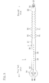
- FIG. 1 shows a band 1 according to an embodiment of the present invention.
- the band 1 is an integral molded product obtained by molding a flexible resin material, and can be used for hanging various containers or for bundling various members together, for example.
- the resin material molded into the band 1 may be, for example, polyethylene, polypropylene, or the like, but it is not limited thereto. It is in a ring shape as shown in FIG. 2 when used, and it is in a generally flat plate shape as shown in FIGS. 3 and 4 when not used.
- the band 1 includes a strip portion 2, wherein an upper surface 2a of the strip portion 2 is the surface to be the outer periphery surface when in a ring form, and a reverse surface 2b of the strip portion 2 is the surface to be the inner periphery surface.
- the strip portion 2 includes a proximal portion (the left end portion in FIGS. 1 , 3 and 4 ) 20, an intermediate portion 21, and a distal portion (the right end portion in FIGS. 1 , 3 and 4 ) 22.
- the width of the proximal portion 20 is set to be wider than the width of the distal portion 22 and the intermediate portion 21.
- Many engagement holes 30, 30, ... are formed in a proximal end portion of the intermediate portion 21, and many first teeth 31, 31, ...
- first and second teeth 31 and 32 are formed in a distal end portion of the intermediate portion 21. That is, the widest portion of the strip portion 2 is the proximal portion 20, and the portion on the distal end side of the first and second teeth 31 and 32 is the distal portion 22.
- the thickness of the intermediate portion 21 and that of the distal portion 22 are set to be equal to each other.
- the distal portion 22 is formed in a tapered shape whose width decreases toward the distal end of the strip portion 2.
- the distal portion of the distal portion 22 is rounded.
- a plurality of ridge portions 33, 33, ... , extending in the width direction are formed with an interval therebetween in the longitudinal direction of the strip portion 2 at the distal end of the reverse surface of the distal portion 22.
- the ridge portions 33, 33, ... serve as non-slip means for holding the distal portion 22 by hand.
- an engagement protrusion 34 is formed on the proximal end side of the ridge portions 33 on the reverse surface of the distal portion 22.
- the engagement protrusion 34 is in a cylindrical shape and is placed at generally the central portion in the width direction.
- the axial line of the engagement protrusion 34 is perpendicular to the reverse surface of the distal portion 22.
- first teeth 31, 31, ... are formed in series in the longitudinal direction of the strip portion 2 on one side of the intermediate portion 21 in the width direction (the upper side in FIG. 1 ), and many second teeth 32, 32, ... , are similarly formed on the other side in the width direction (the lower side in FIG. 1 ).
- first and second teeth 31 and 32 With the first and second teeth 31 and 32, the opposite sides of the intermediate portion 21 in the width direction are in a saw-toothed shape.
- the first teeth 31 and the second teeth 32 are placed at the same position with respect to the longitudinal direction of the intermediate portion 21.
- an edge portion 31a of each first tooth 31 on the distal end side of the strip portion 2 extends along a straight line.
- An edge portion 31b of each first tooth 31 on the proximal end side of the strip portion 2 extends along a straight line in a direction perpendicular to the center line X extending in the longitudinal direction of the strip portion 2. While the angle ⁇ formed between the edge portion 31b and the center line X extending in the longitudinal direction of the strip portion 2 is set to 90° in the present embodiment, it is not limited thereto, and the angle ⁇ may be any angle within a range of 80° or more and 120° or less.
- An outer edge portion 31c of each first tooth 31 extends in the longitudinal direction of the strip portion 2.
- the second teeth 32 have the same shape as the first teeth 31, and the edge portions of each second tooth 32 extend similarly to the edge portions 31a-31 of the first tooth 31.
- the engagement holes 30 of the intermediate portion 21 are formed so that the engagement protrusion 34 of the distal portion 22 can fit in and engage with an engagement hole 30.
- the engagement holes 30 are formed in a generally circular shape, and are formed with an interval therebetween in the longitudinal direction of the strip portion 2 in the central portion of the intermediate portion 21 in the width direction. The interval between the engagement holes 30 is set to be equal to the interval between the first teeth 31.
- the edge portion of the proximal portion 20 on the proximal end side is formed along a straight line perpendicular to the longitudinal direction of the strip portion 2 as viewed from above.
- the opposite edge portions of the proximal portion 20 in the width direction are both in an arc shape as viewed from above, and are continuous with the edge portion on the proximal end side. That is, the width size of the proximal portion 20 is greatest in the central portion thereof in the longitudinal direction (the direction of the center line X in FIG. 6 ), and decreases toward either end thereof in the longitudinal direction. Since the opposite edge portions of the proximal portion 20 in the width direction each have a corner-less arc shape, one will not feel a pain when holding the proximal portion 20 by hand, and the proximal portion 20 will not get caught on other members.
- a first thick portion 41 and a second thick portion 42 which are thicker than the central portion in the width direction, are formed so as to protrude in the direction of the upper surface 2a of the strip portion 2, and a thin portion 43 having the same thickness as that of the intermediate portion 21 and the distal portion 22 is formed between the first and second thick portions 41 and 42.
- the first thick portion 41 and the thin portion 43 together form a first step portion 44 on the upper surface of the proximal portion 20 and, similarly, the second thick portion 42 and the thin portion 43 together form a second step portion 45.
- the interval between the first and second thick portions 41 and 42 is set so that the intermediate portion 21 and the distal portion 22 can be inserted into the space between the thick portions 41 and 42, i.e., generally equal to, or slightly larger than, the width size of the intermediate portion 21.
- a plurality of ridge portions 46, 46, ... , and ridge portions 47, 47, ... , extending in the longitudinal direction of the strip portion 2 are formed with an interval therebetween in the width direction on the upper surface of the first and second thick portions 41 and 42.
- the ridge portions 46 and 47 serve as non-slip means for holding the first and second thick portions 41 and 42 by hand.
- First to fourth protruding portions 51-54 are formed on the thin portion 43.
- the first tooth 31 is engaged to the first and second protruding portions 51 and 52
- the second tooth 32 is engaged to the third and fourth protruding portions 53 and 54.
- the first and second protruding portions 51 and 52 protrude from the upper surface of the thin portion 43, and are continuous with the first thick portion 41, while extending toward the second thick portion 42.
- the third and fourth protruding portions 53 and 54 protrude from the upper surface of the thin portion 43, and are continuous with the second thick portion 42, while extending toward the first thick portion 41.
- the first to fourth protruding portions 51-54 protrude from the upper surface of the thin portion 43 by an equal amount, which is set to be greater than the thickness size of the intermediate portion 21 and the distal portion 22.
- the amount by which the first to fourth protruding portions 51-54 protrude from the upper surface of the thin portion 43 may be equal to the thickness size of the intermediate portion 21 and the distal portion 22.
- the amount by which the first to fourth protruding portions 51-54 protrude from the upper surface of the thin portion 43 is set to be preferably less than or equal to 2.0 times, and more preferably 1.4 times, the thickness size of the intermediate portion 21 and the distal portion 22.
- the first protruding portion 51 and the second protruding portion 52 are placed with a predetermined interval therebetween in the longitudinal direction of the strip portion 2.
- the interval corresponds to the shape of the first teeth 31, and is set so that the first teeth 31 can each fit in between the protruding portions 51 and 52.
- the third protruding portion 53 and the fourth protruding portion 54 are similarly placed with an interval therebetween.
- the first protruding portion 51 and the third protruding portion 53 are placed with an interval therebetween in the width direction of the proximal portion 20 while opposing each other in the width direction of the proximal portion 20.
- the second protruding portion 52 and the fourth protruding portion 54 are similarly placed with an interval therebetween in the width direction of the proximal portion 20 and are opposing each other.
- An edge portion 51a of the first protruding portion 51 on the proximal end side of the strip portion 2 is inclined so that portions thereof closer to the second thick portion 42 are located closer to the distal end of the strip portion 2.
- the edge portion 51a on the proximal end side conforms with the edge portion 31 a of the first teeth 31.
- an edge portion 51b of the first protruding portion 51 on the distal end side of the strip portion 2 extends generally perpendicular to the center line X extending in the longitudinal direction of the strip portion 2, and conforms with the edge portion 31b of the first teeth 31. That is, as shown in FIG.
- the angle ⁇ formed between the edge portion 51b of the first protruding portion 51 and the center line X extending in the longitudinal direction of the strip portion 2 is set to be equal to the angle ⁇ .
- An edge portion 51c of the first protruding portion 51 opposing the third protruding portion 53 extends in the longitudinal direction of the strip portion 2, and conforms with the edge portion 31c of the first teeth 31. That is, the first protruding portion 51 has a shape corresponding to the shape of each first tooth 31.
- the second to fourth protruding portions 52-54 have the same shape as that of the first protruding portion 51, and edge portions of the second to fourth protruding portions 52-54 extend similarly to the edge portions 51a-51c of the first protruding portion 51.
- a first stopper portion 61 is formed on, and integral with, the upper surface of the first thick portion 41, and a second stopper portion 62 is formed on, and integral with, the upper surface of the second thick portion 42.
- the first stopper portion 61, the first protruding portion 51 and the second protruding portion 52 together form engaging means for engaging the first teeth 31, and the second stopper portion 62, the third protruding portion 53 and the fourth protruding portion 54 together form engaging means for engaging the second teeth 32.
- the first and second stopper portions 61 and 62 are opposing each other in the width direction of the proximal portion 20.
- the first stopper portion 61 protrudes from the upper surface of the first thick portion 41, and extends from the first protruding portion 51 to the second protruding portion 52 along an edge portion of the first thick portion 41 on the side of the thin portion 43. That is, the first protruding portion 51 and the second protruding portion 52 are coupled with each other by the first stopper portion 61.
- the second stopper portion 62 extends so as to couple together the third protruding portion 53 and the fourth protruding portion 54.
- the protrusion height H (shown in FIG. 7(b) ) of the first stopper portion 61 from the upper surface of the first thick portion 41 is set to be 0.5 mm or more and 3.0 mm or less.
- the protrusion height of the second stopper portion 62 is set similarly to this.
- the space between the first stopper portion 61 and the second stopper portion 62 is open, and the open space serves as a release portion S between the first and second protruding portions 51 and 52 and the third and fourth protruding portions 53 and 54.
- the release portion S serves to allow a portion of the intermediate portion 21 where the first and second teeth 31 and 32 are formed to be moved into and out of the space between the first and second protruding portions 51 and 52 and the third and fourth protruding portions 53 and 54.
- the first stopper portion 61 protrudes from the first thick portion 41 toward the second thick portion 42.
- the separation size R (shown in FIG. 7(c) ) between the first stopper portion 61 and the upper surface of the thin portion 43 is set to be greater than the thickness of the intermediate portion 21 and the distal portion 22 by a factor of 1.0 or more and 2.0 or less.
- An opposing surface 61a of the first stopper portion 61 opposing the second stopper portion 62 is inclined in such a direction that portions thereof further away from the thin portion 43 in the thickness direction are located further away from the second stopper portion 62.
- An opposing surface 62a of the second stopper portion 62 is also inclined similarly.
- a hole (weakened portion) 65 extending in the longitudinal direction of the strip portion 2 is formed in the thin portion 43 of the proximal portion 20.
- the hole 65 is positioned in the central portion of the proximal portion 20 in the width direction, and serves to weaken the central portion of the proximal portion 20 in the width direction as compared with other portions. With the formation of the hole 65, the proximal portion 20 can be bent more easily at around the central portion in the width direction, as shown in FIG. 8 .
- the length of the hole 65 is preferably set to be 40 mm or less.
- the width of the hole 65 is preferably set to be 0.5 mm or more and 7.0 mm or less, and is more preferably set to be 4.0 mm or less.
- the sizes of the hole 65 are not limited to those described above, but may be set otherwise as appropriate.
- reference numeral 66 in the figures denotes through holes that are left void when a mold is taken out in the molding process.
- the intermediate portion 21 of the strip portion 2 is bent as shown in FIG. 2 .
- the intermediate portion 21 is inserted, through the release portion S, into the space between the first and second protruding portions 51 and 52 and the third and fourth protruding portions 53 and 54.
- the opposing surface 61 a of the first stopper portion 61 is inclined as described above, the first tooth 31 can be pushed toward the thin portion 43, whereby the first tooth 31 slides on the opposing surface 61a while being deformed elastically and gets over the first stopper portion 61 so as to be engaged to the first and second protruding portions 51 and 52.
- the second tooth 32 slides on the opposing surface 62a of the second stopper portion 62 while being deformed elastically and gets over the second stopper portion 62 so as to be engaged to the third and fourth protruding portions 53 and 54. That is, the strip portion 2 is guided by the opposing surfaces 61a and 62a into the space between the protruding portions 51 and 52 and the protruding portions 53 and 54, and therefore the opposing surfaces 61a and 62a serve as the guide surface of the present invention.
- the intermediate portion 21 is laid on the upper surface of the thin portion 43 of the proximal portion 20.
- the proximal portion 20 may be deformed so as to move the first stopper portion 61 and the second stopper portion 62 away from each other, as shown in FIG. 8 .
- the first tooth 31 and the second tooth 32 can be easily engaged to the protruding portions 51-54 and the first and second stopper portions 61 and 62.
- the engagement protrusion 34 is fitted into, and engaged with, the engagement hole 30.
- the first and second teeth 31 and 32 are prevented by the first and second stopper portions 61 and 62 from being unhooked in the thickness direction of the strip portion 2 and are kept engaged with the protruding portions 51-54, as shown in FIG. 9(b) .
- the engagement protrusion 34 is engaged with the engagement hole 30, the distal portion 22 of the strip portion 2 is unlikely to be lifted off the intermediate portion 21 when a tensile load is applied. This also makes it more unlikely that the first and second teeth 31 and 32 are unhooked from the protruding portions 51-54.
- the intermediate portion 21 does not move in either longitudinal direction, and the diameter of the ring does not increase or decrease. Note that when forming the ring, the distal portion 22 may be bent, or the proximal portion 20 may be bent.
- the strip portion 2 in a ring form is turned back into the original shape.
- the first thick portion 41 and the second thick portion 42 are held by hand, and the proximal portion 20 is bent in such a direction that the stopper portions 61 and 62 are moved away from each other, as shown in FIG. 10 .
- the first tooth 31 is unhooked from the first and second protruding portions 51 and 52
- the second tooth 32 is unhooked from the third and fourth protruding portions 53 and 54.
- the intermediate portion 21 is pulled out, via the release portion S, from the space between the first and second protruding portions 51 and 52 and the third and fourth protruding portions 53 and 54.
- the first and second teeth 31 and 32 When adjusting the diameter of the ring, the first and second teeth 31 and 32 may be unhooked from the first to fourth protruding portions 51-54 as described above, and then the strip portion 2 may be bent so as to achieve an intended diameter, whereupon another set of first and second teeth 31 and 32 are engaged to the first to fourth protruding portions 51-54 and the first and second stopper portions 61 and 62.
- the band 1 of the present embodiment includes the first teeth 31 and the second teeth 32 formed on opposite sides of the strip portion 2 in the width direction, and the first to fourth protruding portions 51-54 and the first and second stopper portions 61 and 62 formed in the proximal portion 20 so as to hold the first teeth 31 and the second teeth 32, with the release portion S provided serving to allow the strip portion 2 to be moved into and out of the space between the first protruding portion 51, the second protruding portion 52 and the first stopper portion 61, and the third protruding portion 53, the fourth protruding portion 54 and the second stopper portion 62.
- the proximal portion 20 of the strip portion 2 is formed wider than the intermediate portion 21 and the distal portion 22, the proximal portion 20 can be held firmly when engaging the first teeth 31 and the second teeth 32 to the first to fourth protruding portions 51-54 or when unhooking them from the protruding portions 51-54, thus improving the usability.
- first and second thick portions 41 and 42 are formed on opposite sides of the proximal portion 20 in the width direction, with the first and second stopper portions 61 and 62 being integral with the thick portions 41 and 42, it is possible to easily displace the first and second stopper portions 61 and 62 when unhooking the first teeth 31 and the second teeth 32 from the first to fourth protruding portions 51-54, thus further improving the usability.
- first and second protruding portions 51 and 52 and the third and fourth protruding portions 53 and 54 are shaped so as to protrude from the upper surface of the proximal portion 20 while opposing each other, it is possible to reduce the play of the strip portion 2 in the width direction in a state where the first teeth 31 and the second teeth 32 are engaged to the first to fourth protruding portions 51-54.
- first and second stopper portions 61 and 62 are apart from the upper surface of the thin portion 43 in the thickness direction of the strip portion 2, the first teeth 31 and the second teeth 32 do not move in the thickness direction of the strip portion 2 in a state where the first teeth 31 and the second teeth 32 are engaged to the first to fourth protruding portions 51-54, and it is therefore possible to reliably prevent the first teeth 31 and the second teeth 32 from being unhooked inadvertently.
- the first teeth 31 and the second teeth 32 can be easily engaged to the first to fourth protruding portions 51-54.
- the hole 65 is provided in an area of the proximal portion 20 of the strip portion 2 between the first and second protruding portions 51 and 52 and the third and fourth protruding portions 53 and 54, it is possible to easily displace the first and second stopper portions 61 and 62 by deforming the proximal portion 20, thus further improving the usability.
- the shape of the edge portion of the proximal portion 20 may be a polygonal shape as in Variation 1 shown in FIG. 11 .
- the first stopper portion 61 is extended toward the proximal end of the strip portion 2 past the first protruding portion 51 and toward the distal end of the strip portion 2 past the second protruding portion 52.
- the second stopper portion 62 is extended similarly, and can hold a plurality of second teeth 32.
- the weakened portion of the present invention is a single hole 65 running through the proximal portion 20 in the embodiment above, the present invention is not limited thereto. It may be a groove 70 as in Variation 2 shown in FIG. 12 , or may be a plurality of holes 71, 71, ... , as in Variation 3 shown in FIG. 13 . Although not shown, the weakened portion may be a plurality of grooves or a combination of a groove and a hole. The weakened portion may be a thin hinge, or the like.
- the teeth may be formed in the distal portion 22.
- One of the first and second stopper portions 61 and 62 may be omitted. While four protruding portions 51-54 are provided in the embodiment above, the number of protruding portions is not limited thereto.
- a bag set may be provided, including the band 1 and a bag (container) as a set.
- the bag may be a urine bag, for example.
- a urine bag is a bag for holding urine drawn out of a patient in a clinical scene, and is well known in the art. In this case, the operation of hanging a urine bag can be done simply and quickly. It is also possible to prevent the hung urine bag from falling inadvertently, thereby improving the reliability of the medical procedure.
- the type of the bag is not limited to this, but may be any of various bags to be hung.
- the band 1 may be provided, as a set, with any of various medical instruments.
- the band of the present invention can be used for hanging various bags in a clinical scene, for example.
Landscapes
- Health & Medical Sciences (AREA)
- General Health & Medical Sciences (AREA)
- Mechanical Engineering (AREA)
- Nursing (AREA)
- Life Sciences & Earth Sciences (AREA)
- Animal Behavior & Ethology (AREA)
- Engineering & Computer Science (AREA)
- Public Health (AREA)
- Veterinary Medicine (AREA)
- Package Frames And Binding Bands (AREA)
- Installation Of Indoor Wiring (AREA)
- Clamps And Clips (AREA)
- Medical Preparation Storing Or Oral Administration Devices (AREA)
- Infusion, Injection, And Reservoir Apparatuses (AREA)
Abstract
Description
- The present invention relates to a band for use in hanging various containers or bundling various members together, and a bag set including such a band.
- As disclosed in
Patent Document 1, for example, a band of this type known in the prior art is so configured that a bendable strip portion is formed into, and held as, a ring during use. The proximal portion of the strip portion includes a through hole through which the strip portion is passed from the distal portion thereof, and the intermediate portion of the strip portion includes many teeth formed in series of a saw-toothed pattern. A engaging portion for engaging a tooth is provided on the inner periphery of the through hole. The engaging portion can be moved by operating a tab portion integral with the engaging portion. - When using the band, first, the strip portion is bent and the distal portion is passed into the through hole, thereby forming the strip portion into a ring. When the strip portion is passed through the through hole from the distal portion thereof, a tooth is engaged to the engaging portion, and the strip portion is kept in the ring form. Thus, it is possible to hang various containers or bundle various members together. When adjusting the diameter of the ring, the tab portion is operated to unhook the engaging portion from the tooth, after which the strip portion is pulled in a direction out of the through hole or passed deeper into the through hole, thereby engaging a different tooth to the engaging portion. When turning the strip portion in the ring form back into a flat shape, the strip portion is pulled out of the through hole similarly after the engaging portion is unhooked from the tooth.
- PATENT DOCUMENT 1: Japanese Laid-Open Patent Publication No.
2003-47139 - With the band of
Patent Document 1, however, when forming the strip portion into a ring, it is necessary to pass the strip portion into the through hole from the distal portion thereof, thus resulting in a troublesome operation. When turning the strip portion back into the original shape from the ring form, it is necessary to pull the strip portion out of the through hole by the amount it has been passed into the through hole, thus also resulting in a troublesome operation. In addition, while the strip portion is moved through the through hole when forming the strip portion into a ring, when turning it back into the original shape and when adjusting the diameter of the ring, the teeth may get caught on the engaging portion because the engaging portion is present on the inner periphery of the through hole, and the teeth may get caught on edges of the through hole other than the engaging portion. As described above, with the band ofPatent Document 1, a troublesome operation is required, and it is difficult to quickly perform the operation. - The present invention has been made in view of the above, and has an object to provide a band that is used in a ring form kept by engaging teeth to engaging means, wherein the operation can be performed easily and quickly.
- In the present invention, in order to achieve the object set forth above, engaging means are formed in a proximal portion of the strip portion while being spaced apart from each other in the width direction for respectively engaging teeth formed on opposite sides of the strip portion in the width direction, with a release portion formed between these engaging means so that the strip portion can be moved into and out by using the release portion.
- Specifically, a first aspect is directed to a strip portion including a proximal portion, an intermediate portion and a distal portion; engaging means formed on a surface of the proximal portion in one thickness direction thereof; and a plurality of teeth formed in series in a longitudinal direction of the strip portion in at least a portion of the distal portion and the intermediate portion, wherein the strip portion is formed into a ring by bending at least a portion of the strip portion, overlapping a portion of an area from the distal portion to the intermediate portion on the surface of the proximal portion in one thickness direction, and engaging one of the teeth to the engaging means, and a diameter of the ring is configured to be adjusted by selecting one of the teeth engaged to the engaging means, the teeth are formed on opposite sides of the strip portion in a width direction, a plurality of the engaging means are formed spaced apart from each other in the width direction of the proximal portion so as to respectively engage the teeth on opposite sides of the strip portion in the width direction, and a release portion is provided between the engaging means for allowing the portion of the distal portion and the intermediate portion where the teeth are formed to be moved into and out of a space between the engaging means.
- With this configuration, when holding the strip portion in a ring, the intermediate portion of the strip portion, for example, is bent, and the intermediate portion is inserted, through the release portion, into the space between the engaging means, overlapping the intermediate portion on the surface of the proximal portion in one thickness direction, and engaging the teeth to the engaging means. When turning the strip portion in a ring form back into the original shape, the intermediate portion is pulled out, via the release portion, from the space between the engaging means, thereby allowing the teeth to be unhooked from the engaging means. When adjusting the diameter of the ring, the teeth are unhooked from the engaging means as described above and the intermediate portion is pulled out, via the release portion, from the space between the engaging means, after which different portions of the strip portion are bent so as to achieve an intended diameter, and the intermediate portion, for example, is inserted into the space between the engaging means through the release portion so as to engage other teeth to the engaging means. Note that teeth in the distal portion may be engaged to, and unhooked from, the engaging means, as described above.
- That is, when forming the strip portion into a ring by engaging the teeth to the engaging means, when turning the strip portion back into the original shape by unhooking the teeth from the engaging means, and when adjusting the diameter of the ring, it is not necessary, as is in the prior art, to move the strip portion through the through hole, but the strip portion can be moved into and out of the space between the engaging means via the release portion, and therefore the teeth of the strip portion will not get caught on the engaging means.
- A second aspect is according to the first aspect, wherein the engaging means includes a stopper portion for preventing the tooth from being unhooked in a thickness direction of the strip portion.
- With this configuration, it is possible with the stopper portion to prevent the tooth from being unhooked in a state where the tooth is engaged to the engaging means.
- A third aspect is according to the second aspect, wherein the stopper portion is spaced apart from the surface of the proximal portion in one thickness direction in the thickness direction of the strip portion.
- With this configuration, the tooth engaged to the engaging means is located between the surface of the proximal portion in one thickness direction and the stopper portion, thereby preventing the tooth from moving in the thickness direction of the strip portion.
- A fourth aspect is according to the second or third aspect, wherein the stopper portion includes a guide surface formed thereon for guiding the strip portion into the space between the engaging means.
- With this configuration, when a portion of the strip portion where the teeth are formed is inserted into the space between the engaging means, the strip portion is guided by the guide surface of the stopper portion.
- A fifth aspect is according to one of the first to fourth aspects, wherein the proximal portion of the strip portion is formed wider than the intermediate portion and the distal portion.
- With this configuration, since the proximal portion is formed wider than the intermediate portion and the distal portion, the proximal portion can be held firmly by hand when engaging the teeth to the engaging means or when unhooking the teeth from the engaging means.
- A sixth aspect is according to one of the first to fifth aspects, wherein a thick portion, which is thicker than a central portion of the proximal portion in the width direction, is formed on each side of the proximal portion in the width direction, and the engaging means is integral with the thick portions.
- With this configuration, a central portion of the proximal portion in the width direction is more easily deformed as compared with the opposite side portions. Therefore, the engaging means can be easily displaced when unhooking the teeth from the engaging means.
- A seventh aspect is according to one of the first to sixth aspects, wherein the engaging means include protruding portions protruding from the surface of the proximal portion in one thickness direction and facing each other in the width direction of the proximal portion.
- With this configuration, the protruding portions engage the teeth from opposite sides of the strip portion in the width direction.
- An eighth aspect is according to one of the first to seventh aspects, wherein the proximal portion of the strip portion includes a weakened portion provided between the engaging means.
- With this configuration, a portion of the proximal portion between the engaging means is easily deformed. Thus, it is possible to easily displace the engaging means.
- A ninth aspect is according to the eighth aspect, wherein the weakened portion is a hole running through the proximal portion of the strip portion in the thickness direction.
- With this configuration, the structure of the weakened portion is simple.
- A tenth aspect is directed to a bag set including, as a set, the band as set forth above and a bag.
- According to the first aspect, teeth are formed on opposite sides of the strip portion in the width direction, and a plurality of engaging means are formed spaced apart from each other in the width direction of the strip portion so as to engage the teeth on opposite sides, with a release portion for allowing the strip portion to be moved into and out of the space between the engaging means. Therefore, when forming the strip portion into a ring, when turning it back into the original shape, and when adjusting the diameter of the ring, the teeth of the strip portion will not get caught on the engaging means, and the operation can be performed easily and quickly.
- According to the second aspect, it is possible, with the stopper portion, to prevent the teeth from being unhooked inadvertently in a state where the teeth are engaged to the engaging means. Therefore, the strip portion can be held in a ring form even if a large load acts upon the strip portion in a ring form.
- According to the third aspect, since the stopper portion is spaced apart, in the thickness direction of the strip portion, from the surface of the proximal portion in one thickness direction, the teeth engaged to the engaging means are located between the surface of the proximal portion and the stopper portion, and it is possible to reliably prevent the teeth from being unhooked inadvertently from the engaging means.
- According to the fourth aspect, the portion of the strip portion where the teeth are formed can be guided by the guide surface of the stopper portion into the space between the engaging means, and it is therefore possible to easily engage the teeth to the engaging means.
- According to the fifth aspect, since the proximal portion of the strip portion is formed wider than the intermediate portion and the distal portion, the proximal portion can be held firmly when engaging the teeth to the engaging means or when unhooking the teeth from the engaging means, thereby improving the usability.
- According to the sixth aspect, since a thick portion is formed on each side of the proximal portion in the width direction, and the engaging means is integral with the thick portion, the engaging means can be easily displaced when unhooking the teeth from the engaging means, thereby further improving the usability.
- According to the seventh aspect, since the engaging means include protruding portions facing each other in the width direction of the proximal portion, it is possible to reduce the play of the strip portion in the width direction in a state where the teeth are engaged to the engaging means.
- According to the eighth aspect, since the proximal portion of the strip portion includes a weakened portion provided between the engaging means, the engaging means can be easily displaced, thereby further improving the usability.
- According to the ninth aspect, it is possible to easily obtain the weakened portion.
- According to the tenth aspect, the operation of hanging a bag or fixing a bag to a fixture can be performed easily and quickly.
-
- [
FIG. 1] FIG. 1 is a plan view of a band of an embodiment. - [
FIG. 2] FIG. 2 is a side view of the band of which the strip portion has been formed into a ring. - [
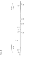
FIG. 3] FIG. 3 is a bottom view of the band. - [
FIG. 4] FIG. 4 is a side view of the band. - [
FIG. 5] FIG. 5 is a plan view showing, on an enlarged scale, a portion of the band of which the strip portion has been formed into a ring. - [
FIG. 6] FIG. 6 is a plan view showing, on an enlarged scale, a proximal portion of the strip portion. - [
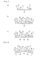
FIG. 7] FIG. 7(a) is a cross-sectional view taken along line A-A ofFIG. 6 ,FIG. 7(b) is a cross-sectional view taken along line B-B ofFIG. 6 , andFIG. 7(c) is a cross-sectional view taken along line C-C ofFIG. 6 . - [
FIG. 8] FIG. 8 is a view corresponding toFIG. 7(c) where the proximal portion is bent. - [
FIG. 9] FIG. 9 shows the strip portion in a ring form, whereFIG. 9(a) corresponds toFIG. 7(b) , andFIG. 9(b) corresponds toFIG. 7(c) . - [
FIG. 10] FIG. 10 is a view corresponding toFIG. 9(b) illustrating a case where teeth are unhooked from stopper portions. - [
FIG. 11] FIG. 11 is a view corresponding toFIG. 6 according toVariation 1. -
FIG. 12] FIG. 12 is a view corresponding toFIG. 7(b) according toVariation 2. - [
FIG. 13] FIG. 13 is a view corresponding toFIG. 6 according toVariation 3. -
- 1
- Band
- 2
- Strip portion
- 20
- Proximal portion
- 21
- Intermediate portion
- 22
- Distal portion
- 31, 32
- First teeth, second teeth
- 41, 42
- First thick portion, second thick portion
- 51-54
- First to fourth protruding portions (protruding portions)
- 61, 62
- First stopper portion, second stopper portion
- 61 a, 62a
- First opposing surface, second opposing surface (guide surface)
- 65
- Hole (weakened portion)
- 70
- Groove (weakened portion)
- 71
- Hole (weakened portion)
- S
- Release portion
- Embodiments of the present invention will now be described in detail with reference to the drawings. Note that the following description of preferred embodiments is merely illustrative of the present invention, and is not intended to limit the present invention or the application and uses thereof.
-
FIG. 1 shows aband 1 according to an embodiment of the present invention. Theband 1 is an integral molded product obtained by molding a flexible resin material, and can be used for hanging various containers or for bundling various members together, for example. The resin material molded into theband 1 may be, for example, polyethylene, polypropylene, or the like, but it is not limited thereto. It is in a ring shape as shown inFIG. 2 when used, and it is in a generally flat plate shape as shown inFIGS. 3 and4 when not used. - The
band 1 includes astrip portion 2, wherein anupper surface 2a of thestrip portion 2 is the surface to be the outer periphery surface when in a ring form, and areverse surface 2b of thestrip portion 2 is the surface to be the inner periphery surface. Thestrip portion 2 includes a proximal portion (the left end portion inFIGS. 1 ,3 and4 ) 20, anintermediate portion 21, and a distal portion (the right end portion inFIGS. 1 ,3 and4 ) 22. The width of theproximal portion 20 is set to be wider than the width of thedistal portion 22 and theintermediate portion 21. Many engagement holes 30, 30, ... , are formed in a proximal end portion of theintermediate portion 21, and manyfirst teeth second teeth intermediate portion 21. That is, the widest portion of thestrip portion 2 is theproximal portion 20, and the portion on the distal end side of the first andsecond teeth distal portion 22. The thickness of theintermediate portion 21 and that of thedistal portion 22 are set to be equal to each other. - The
distal portion 22 is formed in a tapered shape whose width decreases toward the distal end of thestrip portion 2. The distal portion of thedistal portion 22 is rounded. As shown inFIG. 3 , a plurality ofridge portions strip portion 2 at the distal end of the reverse surface of thedistal portion 22. Theridge portions distal portion 22 by hand. As shown inFIG. 4 , anengagement protrusion 34 is formed on the proximal end side of theridge portions 33 on the reverse surface of thedistal portion 22. Theengagement protrusion 34 is in a cylindrical shape and is placed at generally the central portion in the width direction. The axial line of theengagement protrusion 34 is perpendicular to the reverse surface of thedistal portion 22. - Many
first teeth strip portion 2 on one side of theintermediate portion 21 in the width direction (the upper side inFIG. 1 ), and manysecond teeth FIG. 1 ). With the first andsecond teeth intermediate portion 21 in the width direction are in a saw-toothed shape. Thefirst teeth 31 and thesecond teeth 32 are placed at the same position with respect to the longitudinal direction of theintermediate portion 21. - As shown in
FIG. 5 , anedge portion 31a of eachfirst tooth 31 on the distal end side of thestrip portion 2 extends along a straight line. Anedge portion 31b of eachfirst tooth 31 on the proximal end side of thestrip portion 2 extends along a straight line in a direction perpendicular to the center line X extending in the longitudinal direction of thestrip portion 2. While the angle α formed between theedge portion 31b and the center line X extending in the longitudinal direction of thestrip portion 2 is set to 90° in the present embodiment, it is not limited thereto, and the angle α may be any angle within a range of 80° or more and 120° or less. Anouter edge portion 31c of eachfirst tooth 31 extends in the longitudinal direction of thestrip portion 2. Thesecond teeth 32 have the same shape as thefirst teeth 31, and the edge portions of eachsecond tooth 32 extend similarly to theedge portions 31a-31 of thefirst tooth 31. - As shown in
FIG. 2 , the engagement holes 30 of theintermediate portion 21 are formed so that theengagement protrusion 34 of thedistal portion 22 can fit in and engage with anengagement hole 30. The engagement holes 30 are formed in a generally circular shape, and are formed with an interval therebetween in the longitudinal direction of thestrip portion 2 in the central portion of theintermediate portion 21 in the width direction. The interval between the engagement holes 30 is set to be equal to the interval between thefirst teeth 31. - As shown in
FIGS. 1 ,3 and6 , the edge portion of theproximal portion 20 on the proximal end side is formed along a straight line perpendicular to the longitudinal direction of thestrip portion 2 as viewed from above. The opposite edge portions of theproximal portion 20 in the width direction are both in an arc shape as viewed from above, and are continuous with the edge portion on the proximal end side. That is, the width size of theproximal portion 20 is greatest in the central portion thereof in the longitudinal direction (the direction of the center line X inFIG. 6 ), and decreases toward either end thereof in the longitudinal direction. Since the opposite edge portions of theproximal portion 20 in the width direction each have a corner-less arc shape, one will not feel a pain when holding theproximal portion 20 by hand, and theproximal portion 20 will not get caught on other members. - As shown in
FIG. 7 , on opposite sides of theproximal portion 20 in the width direction, a firstthick portion 41 and a secondthick portion 42, which are thicker than the central portion in the width direction, are formed so as to protrude in the direction of theupper surface 2a of thestrip portion 2, and athin portion 43 having the same thickness as that of theintermediate portion 21 and thedistal portion 22 is formed between the first and secondthick portions FIG. 7(a) , the firstthick portion 41 and thethin portion 43 together form afirst step portion 44 on the upper surface of theproximal portion 20 and, similarly, the secondthick portion 42 and thethin portion 43 together form asecond step portion 45. The interval between the first and secondthick portions intermediate portion 21 and thedistal portion 22 can be inserted into the space between thethick portions intermediate portion 21. As shown inFIGS. 6 and7 , a plurality ofridge portions ridge portions strip portion 2, are formed with an interval therebetween in the width direction on the upper surface of the first and secondthick portions ridge portions thick portions - First to fourth protruding portions 51-54 are formed on the
thin portion 43. As shown inFIG. 5 , thefirst tooth 31 is engaged to the first and second protrudingportions second tooth 32 is engaged to the third and fourth protrudingportions FIG. 6 , the first and second protrudingportions thin portion 43, and are continuous with the firstthick portion 41, while extending toward the secondthick portion 42. The third and fourth protrudingportions thin portion 43, and are continuous with the secondthick portion 42, while extending toward the firstthick portion 41. The first to fourth protruding portions 51-54 protrude from the upper surface of thethin portion 43 by an equal amount, which is set to be greater than the thickness size of theintermediate portion 21 and thedistal portion 22. Note that the amount by which the first to fourth protruding portions 51-54 protrude from the upper surface of thethin portion 43 may be equal to the thickness size of theintermediate portion 21 and thedistal portion 22. The amount by which the first to fourth protruding portions 51-54 protrude from the upper surface of thethin portion 43 is set to be preferably less than or equal to 2.0 times, and more preferably 1.4 times, the thickness size of theintermediate portion 21 and thedistal portion 22. - The first protruding
portion 51 and the second protrudingportion 52 are placed with a predetermined interval therebetween in the longitudinal direction of thestrip portion 2. The interval corresponds to the shape of thefirst teeth 31, and is set so that thefirst teeth 31 can each fit in between the protrudingportions portion 53 and the fourth protrudingportion 54 are similarly placed with an interval therebetween. The first protrudingportion 51 and the third protrudingportion 53 are placed with an interval therebetween in the width direction of theproximal portion 20 while opposing each other in the width direction of theproximal portion 20. The second protrudingportion 52 and the fourth protrudingportion 54 are similarly placed with an interval therebetween in the width direction of theproximal portion 20 and are opposing each other. - An
edge portion 51a of the first protrudingportion 51 on the proximal end side of thestrip portion 2 is inclined so that portions thereof closer to the secondthick portion 42 are located closer to the distal end of thestrip portion 2. Theedge portion 51a on the proximal end side conforms with theedge portion 31 a of thefirst teeth 31. On the other hand, anedge portion 51b of the first protrudingportion 51 on the distal end side of thestrip portion 2 extends generally perpendicular to the center line X extending in the longitudinal direction of thestrip portion 2, and conforms with theedge portion 31b of thefirst teeth 31. That is, as shown inFIG. 6 , the angle β formed between theedge portion 51b of the first protrudingportion 51 and the center line X extending in the longitudinal direction of thestrip portion 2 is set to be equal to the angle α. Anedge portion 51c of the first protrudingportion 51 opposing the third protrudingportion 53 extends in the longitudinal direction of thestrip portion 2, and conforms with theedge portion 31c of thefirst teeth 31. That is, the first protrudingportion 51 has a shape corresponding to the shape of eachfirst tooth 31. The second to fourth protruding portions 52-54 have the same shape as that of the first protrudingportion 51, and edge portions of the second to fourth protruding portions 52-54 extend similarly to theedge portions 51a-51c of the first protrudingportion 51. - A
first stopper portion 61 is formed on, and integral with, the upper surface of the firstthick portion 41, and asecond stopper portion 62 is formed on, and integral with, the upper surface of the secondthick portion 42. Thefirst stopper portion 61, the first protrudingportion 51 and the second protrudingportion 52 together form engaging means for engaging thefirst teeth 31, and thesecond stopper portion 62, the third protrudingportion 53 and the fourth protrudingportion 54 together form engaging means for engaging thesecond teeth 32. - The first and
second stopper portions proximal portion 20. Thefirst stopper portion 61 protrudes from the upper surface of the firstthick portion 41, and extends from the first protrudingportion 51 to the second protrudingportion 52 along an edge portion of the firstthick portion 41 on the side of thethin portion 43. That is, the first protrudingportion 51 and the second protrudingportion 52 are coupled with each other by thefirst stopper portion 61. Similarly, thesecond stopper portion 62 extends so as to couple together the third protrudingportion 53 and the fourth protrudingportion 54. The protrusion height H (shown inFIG. 7(b) ) of thefirst stopper portion 61 from the upper surface of the firstthick portion 41 is set to be 0.5 mm or more and 3.0 mm or less. The protrusion height of thesecond stopper portion 62 is set similarly to this. - The space between the
first stopper portion 61 and thesecond stopper portion 62 is open, and the open space serves as a release portion S between the first and second protrudingportions portions intermediate portion 21 where the first andsecond teeth portions portions - The
first stopper portion 61 protrudes from the firstthick portion 41 toward the secondthick portion 42. The separation size R (shown inFIG. 7(c) ) between thefirst stopper portion 61 and the upper surface of thethin portion 43 is set to be greater than the thickness of theintermediate portion 21 and thedistal portion 22 by a factor of 1.0 or more and 2.0 or less. An opposingsurface 61a of thefirst stopper portion 61 opposing thesecond stopper portion 62 is inclined in such a direction that portions thereof further away from thethin portion 43 in the thickness direction are located further away from thesecond stopper portion 62. An opposingsurface 62a of thesecond stopper portion 62 is also inclined similarly. - A hole (weakened portion) 65 extending in the longitudinal direction of the
strip portion 2 is formed in thethin portion 43 of theproximal portion 20. Thehole 65 is positioned in the central portion of theproximal portion 20 in the width direction, and serves to weaken the central portion of theproximal portion 20 in the width direction as compared with other portions. With the formation of thehole 65, theproximal portion 20 can be bent more easily at around the central portion in the width direction, as shown inFIG. 8 . The length of thehole 65 is preferably set to be 40 mm or less. The width of thehole 65 is preferably set to be 0.5 mm or more and 7.0 mm or less, and is more preferably set to be 4.0 mm or less. The sizes of thehole 65 are not limited to those described above, but may be set otherwise as appropriate. - Note that
reference numeral 66 in the figures denotes through holes that are left void when a mold is taken out in the molding process. - Next, how the
band 1 having such a configuration is used will be described. First, when forming a ring, theintermediate portion 21 of thestrip portion 2 is bent as shown inFIG. 2 . Then, as shown inFIG. 9 , theintermediate portion 21 is inserted, through the release portion S, into the space between the first and second protrudingportions portions surface 61 a of thefirst stopper portion 61 is inclined as described above, thefirst tooth 31 can be pushed toward thethin portion 43, whereby thefirst tooth 31 slides on the opposingsurface 61a while being deformed elastically and gets over thefirst stopper portion 61 so as to be engaged to the first and second protrudingportions second tooth 32 slides on the opposingsurface 62a of thesecond stopper portion 62 while being deformed elastically and gets over thesecond stopper portion 62 so as to be engaged to the third and fourth protrudingportions strip portion 2 is guided by the opposingsurfaces portions portions surfaces - When the
first tooth 31 and thesecond tooth 32 are engaged to the first to fourth protruding portions 51-54 and the first andsecond stopper portions intermediate portion 21 is laid on the upper surface of thethin portion 43 of theproximal portion 20. When engaging the first teeth and thesecond teeth proximal portion 20 may be deformed so as to move thefirst stopper portion 61 and thesecond stopper portion 62 away from each other, as shown inFIG. 8 . Then, thefirst tooth 31 and thesecond tooth 32 can be easily engaged to the protruding portions 51-54 and the first andsecond stopper portions second teeth second stopper portions engagement protrusion 34 is fitted into, and engaged with, theengagement hole 30. - When a tensile load is applied in the direction of outline arrows in
FIG. 2 , for example, with theband 1 being in a ring form, the first andsecond teeth second stopper portions strip portion 2 and are kept engaged with the protruding portions 51-54, as shown inFIG. 9(b) . Moreover, since theengagement protrusion 34 is engaged with theengagement hole 30, thedistal portion 22 of thestrip portion 2 is unlikely to be lifted off theintermediate portion 21 when a tensile load is applied. This also makes it more unlikely that the first andsecond teeth first tooth 31 is located between the first protrudingportion 51 and the second protrudingportion 52 and thesecond tooth 32 is located between the third protrudingportion 53 and the fourth protrudingportion 54, theintermediate portion 21 does not move in either longitudinal direction, and the diameter of the ring does not increase or decrease. Note that when forming the ring, thedistal portion 22 may be bent, or theproximal portion 20 may be bent. - Next, how the
strip portion 2 in a ring form is turned back into the original shape will be described. First, the firstthick portion 41 and the secondthick portion 42 are held by hand, and theproximal portion 20 is bent in such a direction that thestopper portions FIG. 10 . Then, thefirst tooth 31 is unhooked from the first and second protrudingportions second tooth 32 is unhooked from the third and fourth protrudingportions intermediate portion 21 is pulled out, via the release portion S, from the space between the first and second protrudingportions portions - When adjusting the diameter of the ring, the first and
second teeth strip portion 2 may be bent so as to achieve an intended diameter, whereupon another set of first andsecond teeth second stopper portions - As described above, the
band 1 of the present embodiment includes thefirst teeth 31 and thesecond teeth 32 formed on opposite sides of thestrip portion 2 in the width direction, and the first to fourth protruding portions 51-54 and the first andsecond stopper portions proximal portion 20 so as to hold thefirst teeth 31 and thesecond teeth 32, with the release portion S provided serving to allow thestrip portion 2 to be moved into and out of the space between the first protrudingportion 51, the second protrudingportion 52 and thefirst stopper portion 61, and the third protrudingportion 53, the fourth protrudingportion 54 and thesecond stopper portion 62. Therefore, when turning thestrip portion 2 into a ring, when turning it back into the original shape, and when adjusting the diameter of the ring, thefirst teeth 31 and thesecond teeth 32 of thestrip portion 2 do not get caught on the protruding portions 51-54, thus realizing simple and quick operations. In a state where thefirst tooth 31 and thesecond tooth 32 are engaged to the first to fourth protruding portions 51-54, it is possible with the first andsecond stopper portions teeth strip portion 2 in a ring form. - Since the
proximal portion 20 of thestrip portion 2 is formed wider than theintermediate portion 21 and thedistal portion 22, theproximal portion 20 can be held firmly when engaging thefirst teeth 31 and thesecond teeth 32 to the first to fourth protruding portions 51-54 or when unhooking them from the protruding portions 51-54, thus improving the usability. - Since the first and second
thick portions proximal portion 20 in the width direction, with the first andsecond stopper portions thick portions second stopper portions first teeth 31 and thesecond teeth 32 from the first to fourth protruding portions 51-54, thus further improving the usability. - Since the first and second protruding
portions portions proximal portion 20 while opposing each other, it is possible to reduce the play of thestrip portion 2 in the width direction in a state where thefirst teeth 31 and thesecond teeth 32 are engaged to the first to fourth protruding portions 51-54. - Since the first and
second stopper portions thin portion 43 in the thickness direction of thestrip portion 2, thefirst teeth 31 and thesecond teeth 32 do not move in the thickness direction of thestrip portion 2 in a state where thefirst teeth 31 and thesecond teeth 32 are engaged to the first to fourth protruding portions 51-54, and it is therefore possible to reliably prevent thefirst teeth 31 and thesecond teeth 32 from being unhooked inadvertently. - Since it is possible, with the opposing
surfaces second stopper portions strip portion 2 into the space between the first and second protrudingportions portions first teeth 31 and thesecond teeth 32 can be easily engaged to the first to fourth protruding portions 51-54. - Since the
hole 65 is provided in an area of theproximal portion 20 of thestrip portion 2 between the first and second protrudingportions portions second stopper portions proximal portion 20, thus further improving the usability. - Note that the shape of the edge portion of the
proximal portion 20 may be a polygonal shape as inVariation 1 shown inFIG. 11 . InVariation 1, thefirst stopper portion 61 is extended toward the proximal end of thestrip portion 2 past the first protrudingportion 51 and toward the distal end of thestrip portion 2 past the second protrudingportion 52. Thus, it is possible to hold a plurality offirst teeth 31 by thefirst stopper portion 61. Thesecond stopper portion 62 is extended similarly, and can hold a plurality ofsecond teeth 32. - While the weakened portion of the present invention is a
single hole 65 running through theproximal portion 20 in the embodiment above, the present invention is not limited thereto. It may be agroove 70 as inVariation 2 shown inFIG. 12 , or may be a plurality ofholes Variation 3 shown inFIG. 13 . Although not shown, the weakened portion may be a plurality of grooves or a combination of a groove and a hole. The weakened portion may be a thin hinge, or the like. - The teeth may be formed in the
distal portion 22. One of the first andsecond stopper portions - A bag set may be provided, including the
band 1 and a bag (container) as a set. The bag may be a urine bag, for example. A urine bag is a bag for holding urine drawn out of a patient in a clinical scene, and is well known in the art. In this case, the operation of hanging a urine bag can be done simply and quickly. It is also possible to prevent the hung urine bag from falling inadvertently, thereby improving the reliability of the medical procedure. The type of the bag is not limited to this, but may be any of various bags to be hung. - The
band 1 may be provided, as a set, with any of various medical instruments. - As described above, the band of the present invention can be used for hanging various bags in a clinical scene, for example.
Claims (10)
- A band comprising:a strip portion including a proximal portion, an intermediate portion and a distal portion;engaging means formed on a surface of the proximal portion in one thickness direction thereof; anda plurality of teeth formed in series in a longitudinal direction of the strip portion in at least a portion of the distal portion and the intermediate portion, whereinthe strip portion is formed into a ring by bending at least a portion of the strip portion, overlapping a portion of an area from the distal portion to the intermediate portion on the surface of the proximal portion in one thickness direction, and engaging one of the teeth to the engaging means, and a diameter of the ring is configured to be adjusted by selecting one of the teeth engaged to the engaging means,the teeth are formed on opposite sides of the strip portion in a width direction,a plurality of the engaging means are formed spaced apart from each other in the width direction of the proximal portion so as to respectively engage the teeth on opposite sides of the strip portion in the width direction, anda release portion is provided between the engaging means for allowing the portion of the distal portion and the intermediate portion where the teeth are formed to be moved into and out of a space between the engaging means.
- The band of claim 1, wherein the engaging means includes a stopper portion for preventing the tooth from being unhooked in a thickness direction of the strip portion.
- The band of claim 2, wherein the stopper portion is spaced apart from the surface of the proximal portion in one thickness direction in the thickness direction of the strip portion.
- The band of claim 2 or 3, wherein the stopper portion includes a guide surface formed thereon for guiding the strip portion into the space between the engaging means.
- The band of one of claims 1-4, wherein the proximal portion of the strip portion is formed wider than the intermediate portion and the distal portion.
- The band of one of claims 1-5, wherein
a thick portion, which is thicker than a central portion of the proximal portion in the width direction, is formed on each side of the proximal portion in the width direction, and
the engaging means is integral with the thick portions. - The band of one of claims 1-6, wherein the engaging means include protruding portions protruding from the surface of the proximal portion in one thickness direction and facing each other in the width direction of the proximal portion.
- The band of one of claims 1-7, wherein the proximal portion of the strip portion includes a weakened portion provided between the engaging means.
- The band of claim 8, wherein the weakened portion is a hole running through the proximal portion of the strip portion in the thickness direction.
- A bag set including, as a set, the band of one of claims 1-9 and a bag.
Applications Claiming Priority (2)
| Application Number | Priority Date | Filing Date | Title |
|---|---|---|---|
| JP2007255328 | 2007-09-28 | ||
| PCT/JP2008/002711 WO2009041071A1 (en) | 2007-09-28 | 2008-09-29 | Band and bag set |
Publications (3)
| Publication Number | Publication Date |
|---|---|
| EP2194282A1 true EP2194282A1 (en) | 2010-06-09 |
| EP2194282A4 EP2194282A4 (en) | 2011-10-05 |
| EP2194282B1 EP2194282B1 (en) | 2013-01-09 |
Family
ID=40510975
Family Applications (1)
| Application Number | Title | Priority Date | Filing Date |
|---|---|---|---|
| EP08832898A Not-in-force EP2194282B1 (en) | 2007-09-28 | 2008-09-29 | Band and bag set |
Country Status (5)
| Country | Link |
|---|---|
| US (1) | US8302264B2 (en) |
| EP (1) | EP2194282B1 (en) |
| JP (1) | JP5234002B2 (en) |
| CN (1) | CN101809295B (en) |
| WO (1) | WO2009041071A1 (en) |
Cited By (1)
| Publication number | Priority date | Publication date | Assignee | Title |
|---|---|---|---|---|
| WO2020146201A1 (en) * | 2019-01-07 | 2020-07-16 | Panduit Corp. | Cushion sleeve |
Families Citing this family (14)
| Publication number | Priority date | Publication date | Assignee | Title |
|---|---|---|---|---|
| JP5275129B2 (en) * | 2009-05-11 | 2013-08-28 | 日本飛行機株式会社 | Work temporary fastener |
| JP5275130B2 (en) * | 2009-05-11 | 2013-08-28 | 日本飛行機株式会社 | Work temporary fastener |
| JP5471486B2 (en) * | 2010-01-19 | 2014-04-16 | 住友電装株式会社 | Band clamp for wire harness |
| US8826625B2 (en) * | 2010-01-29 | 2014-09-09 | Rebarb, L.L.C. | Fastener to secure rebar rods and associated methods |
| JP5810583B2 (en) * | 2011-03-30 | 2015-11-11 | 株式会社ジェイ・エム・エス | Fastening band |
| US9021681B2 (en) * | 2012-09-27 | 2015-05-05 | Thomas Dale Owen | Mountable cable tie with fine adjustment and method of use thereof |
| KR200481773Y1 (en) * | 2016-03-03 | 2016-11-08 | 프타 주식회사 | Cable tie for incision type |
| USD848615S1 (en) * | 2016-08-18 | 2019-05-14 | Clinical Biotechnology Research Institute At Rsfh | IV pole attachment device |
| US10479574B2 (en) * | 2017-01-17 | 2019-11-19 | Daniel J. Vorhis | Reusable cable tie |
| CN107606337A (en) * | 2017-09-04 | 2018-01-19 | 无锡市永兴金属软管有限公司 | A kind of adjustable metal hose |
| USD848616S1 (en) * | 2018-02-18 | 2019-05-14 | Clinical Biotechnology Research Institute At Rsfh | Hospital bed attachment device |
| EP4037992B1 (en) * | 2019-10-01 | 2024-04-24 | C.B. Srl Costruzioni Brescianini | Cable tie |
| US11883612B2 (en) | 2020-01-17 | 2024-01-30 | Quest Medical, Inc. | Tubing management band |
| US12214946B2 (en) | 2022-09-16 | 2025-02-04 | Daikin Comfort Technologies Manufacturing, L.P. | Fusible tie band |
Family Cites Families (14)
| Publication number | Priority date | Publication date | Assignee | Title |
|---|---|---|---|---|
| GB948900A (en) * | 1961-12-22 | 1964-02-05 | Schumm Erich | Improvements in or relating to ties of resilient flexible material |
| US3086265A (en) * | 1962-01-02 | 1963-04-23 | Orenick Michael | Closure means for bags |
| AT305415B (en) * | 1969-03-07 | 1973-02-26 | Legrand Sa | Fastening tape |
| US3731347A (en) * | 1971-03-16 | 1973-05-08 | Panduit Corp | Cable tie |
| US4141565A (en) * | 1976-03-15 | 1979-02-27 | Shields Michael P | Adjustable ski strap |
| JP2602680B2 (en) | 1987-12-28 | 1997-04-23 | 鐘淵化学工業株式会社 | Foamable composition and method for producing the same |
| JPH01176436U (en) * | 1988-05-31 | 1989-12-15 | ||
| DE4126225A1 (en) * | 1991-08-08 | 1993-02-11 | Schumm Erich Kg | SEALING TAPE |
| JPH09210020A (en) | 1996-01-31 | 1997-08-12 | Kyoritsu High Parts Kk | Hand clip |
| US6226839B1 (en) * | 1999-01-05 | 2001-05-08 | Adel Odeh Sayegh | Securing means attachable to objects of varying size and shape |
| JP3489029B2 (en) | 2001-05-22 | 2004-01-19 | 享 宮道 | Unity band |
| CN2538709Y (en) | 2002-05-27 | 2003-03-05 | 刘庆海 | Strap for bundling mouth of packing bag |
| CN1919697A (en) * | 2005-08-12 | 2007-02-28 | 泛达公司 | Releasable in-line cable tie |
| US20070033772A1 (en) | 2005-08-12 | 2007-02-15 | Panduit Corp. | Releasable in-line cable tie |
-
2008
- 2008-09-29 WO PCT/JP2008/002711 patent/WO2009041071A1/en not_active Ceased
- 2008-09-29 EP EP08832898A patent/EP2194282B1/en not_active Not-in-force
- 2008-09-29 CN CN2008801093909A patent/CN101809295B/en not_active Expired - Fee Related
- 2008-09-29 US US12/680,276 patent/US8302264B2/en not_active Expired - Fee Related
- 2008-09-29 JP JP2009534195A patent/JP5234002B2/en active Active
Cited By (3)
| Publication number | Priority date | Publication date | Assignee | Title |
|---|---|---|---|---|
| WO2020146201A1 (en) * | 2019-01-07 | 2020-07-16 | Panduit Corp. | Cushion sleeve |
| US10926927B2 (en) | 2019-01-07 | 2021-02-23 | Panduit Corp. | Cushion sleeve |
| KR20210113215A (en) * | 2019-01-07 | 2021-09-15 | 팬듀트 코포레이션 | cushion sleeve |
Also Published As
| Publication number | Publication date |
|---|---|
| EP2194282B1 (en) | 2013-01-09 |
| JPWO2009041071A1 (en) | 2011-01-20 |
| JP5234002B2 (en) | 2013-07-10 |
| CN101809295A (en) | 2010-08-18 |
| EP2194282A4 (en) | 2011-10-05 |
| CN101809295B (en) | 2013-03-13 |
| WO2009041071A1 (en) | 2009-04-02 |
| US20100212118A1 (en) | 2010-08-26 |
| US8302264B2 (en) | 2012-11-06 |
Similar Documents
| Publication | Publication Date | Title |
|---|---|---|
| EP2194282B1 (en) | Band and bag set | |
| EP1156250B1 (en) | Cable clamp | |
| US4008512A (en) | Band clamp of plastics material | |
| GB2308153A (en) | Flexible tie for cables | |
| US9034020B2 (en) | Implant for use for adjacently arranged bone plates | |
| CA2304047A1 (en) | Binding element | |
| JP2003111256A (en) | Cable tie having wide neck | |
| HK1044451A1 (en) | Plastic zipper | |
| EP2590283A1 (en) | A Tie for Fixing an Article to a Surface | |
| EP3160403B1 (en) | Tightening system for orthotics | |
| JPH0752969A (en) | Carrier strip with outer band having a concave edge | |
| EP1244592B1 (en) | Device at a bundle tie | |
| US6758365B2 (en) | Container with handle region to receive a rope handle | |
| US7540069B2 (en) | Binding band | |
| CA2697575C (en) | Fastening element magazine strip | |
| US20040228678A1 (en) | Securing clip | |
| WO2006019002A1 (en) | Tool for mounting corrugated tube | |
| JP2007112511A (en) | Releasable serial type cable tie | |
| US20040007612A1 (en) | Box hand hole reinforcement and method of use | |
| EP2012023B1 (en) | Plate clamp | |
| JPH0214247Y2 (en) | ||
| JP2007050030A (en) | Orthodontic cap and orthodontic attachment | |
| EP1475046B1 (en) | Suture material dispenser | |
| JP4046618B2 (en) | Hair insertion tool | |
| US20230372604A1 (en) | Med-Wire Device |
Legal Events
| Date | Code | Title | Description |
|---|---|---|---|
| PUAI | Public reference made under article 153(3) epc to a published international application that has entered the european phase |
Free format text: ORIGINAL CODE: 0009012 |
|
| 17P | Request for examination filed |
Effective date: 20100331 |
|
| AK | Designated contracting states |
Kind code of ref document: A1 Designated state(s): AT BE BG CH CY CZ DE DK EE ES FI FR GB GR HR HU IE IS IT LI LT LU LV MC MT NL NO PL PT RO SE SI SK TR |
|
| AX | Request for extension of the european patent |
Extension state: AL BA MK RS |
|
| DAX | Request for extension of the european patent (deleted) | ||
| A4 | Supplementary search report drawn up and despatched |
Effective date: 20110901 |
|
| RIC1 | Information provided on ipc code assigned before grant |
Ipc: A61G 7/05 20060101ALI20110826BHEP Ipc: H02G 3/30 20060101ALI20110826BHEP Ipc: B65D 63/12 20060101ALI20110826BHEP Ipc: F16B 2/08 20060101AFI20110826BHEP Ipc: A61J 1/16 20060101ALI20110826BHEP Ipc: B65D 63/10 20060101ALI20110826BHEP |
|
| GRAP | Despatch of communication of intention to grant a patent |
Free format text: ORIGINAL CODE: EPIDOSNIGR1 |
|
| GRAS | Grant fee paid |
Free format text: ORIGINAL CODE: EPIDOSNIGR3 |
|
| GRAA | (expected) grant |
Free format text: ORIGINAL CODE: 0009210 |
|
| AK | Designated contracting states |
Kind code of ref document: B1 Designated state(s): AT BE BG CH CY CZ DE DK EE ES FI FR GB GR HR HU IE IS IT LI LT LU LV MC MT NL NO PL PT RO SE SI SK TR |
|
| REG | Reference to a national code |
Ref country code: GB Ref legal event code: FG4D |
|
| REG | Reference to a national code |
Ref country code: CH Ref legal event code: EP Ref country code: AT Ref legal event code: REF Ref document number: 592917 Country of ref document: AT Kind code of ref document: T Effective date: 20130115 |
|
| REG | Reference to a national code |
Ref country code: IE Ref legal event code: FG4D |
|
| REG | Reference to a national code |
Ref country code: DE Ref legal event code: R096 Ref document number: 602008021599 Country of ref document: DE Effective date: 20130314 |
|
| PG25 | Lapsed in a contracting state [announced via postgrant information from national office to epo] |
Ref country code: SI Free format text: LAPSE BECAUSE OF FAILURE TO SUBMIT A TRANSLATION OF THE DESCRIPTION OR TO PAY THE FEE WITHIN THE PRESCRIBED TIME-LIMIT Effective date: 20130109 |
|
| REG | Reference to a national code |
Ref country code: NL Ref legal event code: VDEP Effective date: 20130109 |
|
| REG | Reference to a national code |
Ref country code: AT Ref legal event code: MK05 Ref document number: 592917 Country of ref document: AT Kind code of ref document: T Effective date: 20130109 |
|
| REG | Reference to a national code |
Ref country code: LT Ref legal event code: MG4D |
|
| PG25 | Lapsed in a contracting state [announced via postgrant information from national office to epo] |
Ref country code: ES Free format text: LAPSE BECAUSE OF FAILURE TO SUBMIT A TRANSLATION OF THE DESCRIPTION OR TO PAY THE FEE WITHIN THE PRESCRIBED TIME-LIMIT Effective date: 20130420 Ref country code: BG Free format text: LAPSE BECAUSE OF FAILURE TO SUBMIT A TRANSLATION OF THE DESCRIPTION OR TO PAY THE FEE WITHIN THE PRESCRIBED TIME-LIMIT Effective date: 20130409 Ref country code: BE Free format text: LAPSE BECAUSE OF FAILURE TO SUBMIT A TRANSLATION OF THE DESCRIPTION OR TO PAY THE FEE WITHIN THE PRESCRIBED TIME-LIMIT Effective date: 20130109 Ref country code: AT Free format text: LAPSE BECAUSE OF FAILURE TO SUBMIT A TRANSLATION OF THE DESCRIPTION OR TO PAY THE FEE WITHIN THE PRESCRIBED TIME-LIMIT Effective date: 20130109 Ref country code: NO Free format text: LAPSE BECAUSE OF FAILURE TO SUBMIT A TRANSLATION OF THE DESCRIPTION OR TO PAY THE FEE WITHIN THE PRESCRIBED TIME-LIMIT Effective date: 20130409 Ref country code: LT Free format text: LAPSE BECAUSE OF FAILURE TO SUBMIT A TRANSLATION OF THE DESCRIPTION OR TO PAY THE FEE WITHIN THE PRESCRIBED TIME-LIMIT Effective date: 20130109 Ref country code: IS Free format text: LAPSE BECAUSE OF FAILURE TO SUBMIT A TRANSLATION OF THE DESCRIPTION OR TO PAY THE FEE WITHIN THE PRESCRIBED TIME-LIMIT Effective date: 20130509 Ref country code: SE Free format text: LAPSE BECAUSE OF FAILURE TO SUBMIT A TRANSLATION OF THE DESCRIPTION OR TO PAY THE FEE WITHIN THE PRESCRIBED TIME-LIMIT Effective date: 20130109 |
|
| PG25 | Lapsed in a contracting state [announced via postgrant information from national office to epo] |
Ref country code: GR Free format text: LAPSE BECAUSE OF FAILURE TO SUBMIT A TRANSLATION OF THE DESCRIPTION OR TO PAY THE FEE WITHIN THE PRESCRIBED TIME-LIMIT Effective date: 20130410 Ref country code: LV Free format text: LAPSE BECAUSE OF FAILURE TO SUBMIT A TRANSLATION OF THE DESCRIPTION OR TO PAY THE FEE WITHIN THE PRESCRIBED TIME-LIMIT Effective date: 20130109 Ref country code: PT Free format text: LAPSE BECAUSE OF FAILURE TO SUBMIT A TRANSLATION OF THE DESCRIPTION OR TO PAY THE FEE WITHIN THE PRESCRIBED TIME-LIMIT Effective date: 20130509 Ref country code: PL Free format text: LAPSE BECAUSE OF FAILURE TO SUBMIT A TRANSLATION OF THE DESCRIPTION OR TO PAY THE FEE WITHIN THE PRESCRIBED TIME-LIMIT Effective date: 20130109 Ref country code: NL Free format text: LAPSE BECAUSE OF FAILURE TO SUBMIT A TRANSLATION OF THE DESCRIPTION OR TO PAY THE FEE WITHIN THE PRESCRIBED TIME-LIMIT Effective date: 20130109 Ref country code: FI Free format text: LAPSE BECAUSE OF FAILURE TO SUBMIT A TRANSLATION OF THE DESCRIPTION OR TO PAY THE FEE WITHIN THE PRESCRIBED TIME-LIMIT Effective date: 20130109 |
|
| PG25 | Lapsed in a contracting state [announced via postgrant information from national office to epo] |
Ref country code: HR Free format text: LAPSE BECAUSE OF FAILURE TO SUBMIT A TRANSLATION OF THE DESCRIPTION OR TO PAY THE FEE WITHIN THE PRESCRIBED TIME-LIMIT Effective date: 20130109 |
|
| PG25 | Lapsed in a contracting state [announced via postgrant information from national office to epo] |
Ref country code: CZ Free format text: LAPSE BECAUSE OF FAILURE TO SUBMIT A TRANSLATION OF THE DESCRIPTION OR TO PAY THE FEE WITHIN THE PRESCRIBED TIME-LIMIT Effective date: 20130109 Ref country code: DK Free format text: LAPSE BECAUSE OF FAILURE TO SUBMIT A TRANSLATION OF THE DESCRIPTION OR TO PAY THE FEE WITHIN THE PRESCRIBED TIME-LIMIT Effective date: 20130109 Ref country code: EE Free format text: LAPSE BECAUSE OF FAILURE TO SUBMIT A TRANSLATION OF THE DESCRIPTION OR TO PAY THE FEE WITHIN THE PRESCRIBED TIME-LIMIT Effective date: 20130109 Ref country code: RO Free format text: LAPSE BECAUSE OF FAILURE TO SUBMIT A TRANSLATION OF THE DESCRIPTION OR TO PAY THE FEE WITHIN THE PRESCRIBED TIME-LIMIT Effective date: 20130109 Ref country code: SK Free format text: LAPSE BECAUSE OF FAILURE TO SUBMIT A TRANSLATION OF THE DESCRIPTION OR TO PAY THE FEE WITHIN THE PRESCRIBED TIME-LIMIT Effective date: 20130109 |
|
| PLBE | No opposition filed within time limit |
Free format text: ORIGINAL CODE: 0009261 |
|
| STAA | Information on the status of an ep patent application or granted ep patent |
Free format text: STATUS: NO OPPOSITION FILED WITHIN TIME LIMIT |
|
| PG25 | Lapsed in a contracting state [announced via postgrant information from national office to epo] |
Ref country code: CY Free format text: LAPSE BECAUSE OF FAILURE TO SUBMIT A TRANSLATION OF THE DESCRIPTION OR TO PAY THE FEE WITHIN THE PRESCRIBED TIME-LIMIT Effective date: 20130109 |
|
| 26N | No opposition filed |
Effective date: 20131010 |
|
| PG25 | Lapsed in a contracting state [announced via postgrant information from national office to epo] |
Ref country code: IT Free format text: LAPSE BECAUSE OF FAILURE TO SUBMIT A TRANSLATION OF THE DESCRIPTION OR TO PAY THE FEE WITHIN THE PRESCRIBED TIME-LIMIT Effective date: 20130109 |
|
| REG | Reference to a national code |
Ref country code: DE Ref legal event code: R097 Ref document number: 602008021599 Country of ref document: DE Effective date: 20131010 |
|
| PG25 | Lapsed in a contracting state [announced via postgrant information from national office to epo] |
Ref country code: MC Free format text: LAPSE BECAUSE OF FAILURE TO SUBMIT A TRANSLATION OF THE DESCRIPTION OR TO PAY THE FEE WITHIN THE PRESCRIBED TIME-LIMIT Effective date: 20130109 |
|
| REG | Reference to a national code |
Ref country code: CH Ref legal event code: PL |
|
| GBPC | Gb: european patent ceased through non-payment of renewal fee |
Effective date: 20130929 |
|
| REG | Reference to a national code |
Ref country code: DE Ref legal event code: R119 Ref document number: 602008021599 Country of ref document: DE Effective date: 20140401 |
|
| REG | Reference to a national code |
Ref country code: FR Ref legal event code: ST Effective date: 20140530 |
|
| REG | Reference to a national code |
Ref country code: IE Ref legal event code: MM4A |
|
| PG25 | Lapsed in a contracting state [announced via postgrant information from national office to epo] |
Ref country code: IE Free format text: LAPSE BECAUSE OF NON-PAYMENT OF DUE FEES Effective date: 20130929 Ref country code: LI Free format text: LAPSE BECAUSE OF NON-PAYMENT OF DUE FEES Effective date: 20130930 Ref country code: GB Free format text: LAPSE BECAUSE OF NON-PAYMENT OF DUE FEES Effective date: 20130929 Ref country code: CH Free format text: LAPSE BECAUSE OF NON-PAYMENT OF DUE FEES Effective date: 20130930 |
|
| PG25 | Lapsed in a contracting state [announced via postgrant information from national office to epo] |
Ref country code: FR Free format text: LAPSE BECAUSE OF NON-PAYMENT OF DUE FEES Effective date: 20130930 Ref country code: DE Free format text: LAPSE BECAUSE OF NON-PAYMENT OF DUE FEES Effective date: 20140401 |
|
| PG25 | Lapsed in a contracting state [announced via postgrant information from national office to epo] |
Ref country code: TR Free format text: LAPSE BECAUSE OF FAILURE TO SUBMIT A TRANSLATION OF THE DESCRIPTION OR TO PAY THE FEE WITHIN THE PRESCRIBED TIME-LIMIT Effective date: 20130109 Ref country code: MT Free format text: LAPSE BECAUSE OF FAILURE TO SUBMIT A TRANSLATION OF THE DESCRIPTION OR TO PAY THE FEE WITHIN THE PRESCRIBED TIME-LIMIT Effective date: 20130109 |
|
| PG25 | Lapsed in a contracting state [announced via postgrant information from national office to epo] |
Ref country code: HU Free format text: LAPSE BECAUSE OF FAILURE TO SUBMIT A TRANSLATION OF THE DESCRIPTION OR TO PAY THE FEE WITHIN THE PRESCRIBED TIME-LIMIT; INVALID AB INITIO Effective date: 20080929 Ref country code: LU Free format text: LAPSE BECAUSE OF NON-PAYMENT OF DUE FEES Effective date: 20130929 |