EP2194227A2 - Système et procédé pour vérifier l'état d'un canon perforateur avant de perforer un trou de forage - Google Patents
Système et procédé pour vérifier l'état d'un canon perforateur avant de perforer un trou de forage Download PDFInfo
- Publication number
- EP2194227A2 EP2194227A2 EP09176479A EP09176479A EP2194227A2 EP 2194227 A2 EP2194227 A2 EP 2194227A2 EP 09176479 A EP09176479 A EP 09176479A EP 09176479 A EP09176479 A EP 09176479A EP 2194227 A2 EP2194227 A2 EP 2194227A2
- Authority
- EP
- European Patent Office
- Prior art keywords
- perforating gun
- communication system
- leak
- sensor
- perforating
- Prior art date
- Legal status (The legal status is an assumption and is not a legal conclusion. Google has not performed a legal analysis and makes no representation as to the accuracy of the status listed.)
- Withdrawn
Links
- 238000000034 method Methods 0.000 title claims description 41
- 230000006854 communication Effects 0.000 claims abstract description 137
- 238000004891 communication Methods 0.000 claims abstract description 137
- 230000007613 environmental effect Effects 0.000 claims description 68
- 239000012530 fluid Substances 0.000 claims description 12
- 230000035939 shock Effects 0.000 claims description 6
- 238000006073 displacement reaction Methods 0.000 claims description 4
- 230000015572 biosynthetic process Effects 0.000 description 9
- 238000010304 firing Methods 0.000 description 9
- 230000008569 process Effects 0.000 description 7
- 230000007175 bidirectional communication Effects 0.000 description 5
- 238000012545 processing Methods 0.000 description 5
- 238000012795 verification Methods 0.000 description 5
- 239000002800 charge carrier Substances 0.000 description 4
- 230000000246 remedial effect Effects 0.000 description 4
- 239000004568 cement Substances 0.000 description 3
- 239000004020 conductor Substances 0.000 description 3
- 238000005474 detonation Methods 0.000 description 2
- 239000002360 explosive Substances 0.000 description 2
- 230000000977 initiatory effect Effects 0.000 description 2
- 238000012986 modification Methods 0.000 description 2
- 230000004048 modification Effects 0.000 description 2
- 238000005979 thermal decomposition reaction Methods 0.000 description 2
- WHXSMMKQMYFTQS-UHFFFAOYSA-N Lithium Chemical compound [Li] WHXSMMKQMYFTQS-UHFFFAOYSA-N 0.000 description 1
- 230000001133 acceleration Effects 0.000 description 1
- 239000002253 acid Substances 0.000 description 1
- OJIJEKBXJYRIBZ-UHFFFAOYSA-N cadmium nickel Chemical compound [Ni].[Cd] OJIJEKBXJYRIBZ-UHFFFAOYSA-N 0.000 description 1
- 239000000919 ceramic Substances 0.000 description 1
- 239000013078 crystal Substances 0.000 description 1
- 238000005553 drilling Methods 0.000 description 1
- 230000006870 function Effects 0.000 description 1
- 230000002706 hydrostatic effect Effects 0.000 description 1
- 230000008595 infiltration Effects 0.000 description 1
- 238000001764 infiltration Methods 0.000 description 1
- 239000003999 initiator Substances 0.000 description 1
- 238000009434 installation Methods 0.000 description 1
- 229910052744 lithium Inorganic materials 0.000 description 1
- 229910052751 metal Inorganic materials 0.000 description 1
- 239000002184 metal Substances 0.000 description 1
- 238000012544 monitoring process Methods 0.000 description 1
- 230000003287 optical effect Effects 0.000 description 1
- 230000000644 propagated effect Effects 0.000 description 1
- 238000011084 recovery Methods 0.000 description 1
- 230000000717 retained effect Effects 0.000 description 1
- 230000000638 stimulation Effects 0.000 description 1
- 230000001052 transient effect Effects 0.000 description 1
Images


Classifications
-
- E—FIXED CONSTRUCTIONS
- E21—EARTH DRILLING; MINING
- E21B—EARTH DRILLING, e.g. DEEP DRILLING; OBTAINING OIL, GAS, WATER, SOLUBLE OR MELTABLE MATERIALS OR A SLURRY OF MINERALS FROM WELLS
- E21B43/00—Methods or apparatus for obtaining oil, gas, water, soluble or meltable materials or a slurry of minerals from wells
- E21B43/11—Perforators; Permeators
- E21B43/116—Gun or shaped-charge perforators
-
- E—FIXED CONSTRUCTIONS
- E21—EARTH DRILLING; MINING
- E21B—EARTH DRILLING, e.g. DEEP DRILLING; OBTAINING OIL, GAS, WATER, SOLUBLE OR MELTABLE MATERIALS OR A SLURRY OF MINERALS FROM WELLS
- E21B43/00—Methods or apparatus for obtaining oil, gas, water, soluble or meltable materials or a slurry of minerals from wells
- E21B43/11—Perforators; Permeators
- E21B43/119—Details, e.g. for locating perforating place or direction
-
- E—FIXED CONSTRUCTIONS
- E21—EARTH DRILLING; MINING
- E21B—EARTH DRILLING, e.g. DEEP DRILLING; OBTAINING OIL, GAS, WATER, SOLUBLE OR MELTABLE MATERIALS OR A SLURRY OF MINERALS FROM WELLS
- E21B47/00—Survey of boreholes or wells
- E21B47/10—Locating fluid leaks, intrusions or movements
- E21B47/117—Detecting leaks, e.g. from tubing, by pressure testing
-
- E—FIXED CONSTRUCTIONS
- E21—EARTH DRILLING; MINING
- E21B—EARTH DRILLING, e.g. DEEP DRILLING; OBTAINING OIL, GAS, WATER, SOLUBLE OR MELTABLE MATERIALS OR A SLURRY OF MINERALS FROM WELLS
- E21B47/00—Survey of boreholes or wells
- E21B47/12—Means for transmitting measuring-signals or control signals from the well to the surface, or from the surface to the well, e.g. for logging while drilling
- E21B47/14—Means for transmitting measuring-signals or control signals from the well to the surface, or from the surface to the well, e.g. for logging while drilling using acoustic waves
Definitions
- This invention relates, in general, to opening communication paths through a casing disposed in a wellbore and, in particular, to systems and methods for verifying the status of perforating guns prior to perforating the wellbore.
- casing string After drilling the various sections of a subterranean wellbore that traverses a formation, individual lengths of relatively large diameter metal tubulars are typically secured together to form a casing string that is positioned within the wellbore.
- This casing string increases the integrity of the wellbore and provides a path for producing fluids from the producing intervals to the surface.
- the casing string is cemented within the wellbore.
- hydraulic openings or perforations must be made through the casing string, the cement and a distance into the formation.
- these perforations are created by detonating a series of shaped charges that are disposed within the casing string and are positioned adjacent to the formation.
- one or more charge carriers or perforating guns are loaded with shaped charges that are connected with a detonator via a detonating cord.
- the charge carriers are then connected within a tool string that is lowered into the cased wellbore at the end of a tubing string or other conveyance. Once the charge carriers are properly positioned in the wellbore such that the shaped charges are adjacent to the formation to be perforated, the shaped charges may be fired.
- a select fire perforating gun assembly may be used such that once the first zone is perforated, subsequent zones may be perforated by repositioning and firing the previously unfired perforating guns without tripping out of the well.
- the charge carriers protect the shaped charges disposed therein against wellbore fluids. It has been found, however, that perforating guns sometimes develop a leak, for example during the run in process, and become partially or completely filled with wellbore fluid. Once such fluid infiltration has occurred, if such a perforating gun is fired, there is a high likelihood that the perforating gun may split. Not only does such an occurrence result in a failed perforation operation, the explosive event may damage other wellbore equipment and may result in the split perforating gun becoming lodged in the wellbore. As such, an expensive recovery effort to retrieve the damaged equipment may be required and the entire completion may have to be abandoned resulting in the need to drill a sidetrack well.
- the present invention disclosed herein provides systems and methods for bidirectional communication between a surface system and a downhole system that enables a determination of whether a perforating gun has experienced a leak prior to firing the perforating gun.
- the systems and methods of the present invention enable such a determination by telemetering encoded signals from the surface system to one or more downhole systems requesting leak status and other environmental information and by telemetering encoded signals from the downhole systems to the surface system including the leak status or other requested environmental information.
- the present invention is directed to a method for verifying perforating gun status prior to perforating the wellbore.
- the method includes running a perforating gun having a leak sensor disposed therein to a target location within the wellbore on a tubing string, integrating a communication system with the tubing string, the communication system operable to communicate with the leak sensor, sending a first telemetry signal via the communication system to interrogate the leak sensor regarding a leak status of the perforating gun, returning a second telemetry signal from the leak sensor via the communication system including the leak status of the perforating gun and determining whether to operate the perforating gun based upon the leak status information.
- the leak sensor may be a moisture sensor. In this embodiment, the method may include determining whether to operate the perforating gun based upon moisture status information. In another embodiment, the leak sensor may be a pressure sensor. In this embodiment, the method may include determining whether to operate the perforating gun based upon pressure status information. In a further embodiment, the communication system may be an acoustic communication system that is integrated with the tubing string. In this embodiment, the method may include sending an acoustic signal encoded with the leak status request to the leak sensor and returning an acoustic signal encoded with the leak status information from the leak sensor.
- the present invention is directed to a method for verifying perforating gun system status prior to perforating a wellbore.
- This method includes running the perforating gun system to a target location within the wellbore on a tubing string, the perforating gun system including a plurality of perforating guns each having a leak sensor disposed therein, integrating a communication system with the tubing string, the communication system operable to communicate with the leak sensors, sending first telemetry signals via the communication system to interrogate the leak sensors regarding a leak status of each of the perforating guns, returning second telemetry signals from the leak sensors via the communication system including the leak status of each of the perforating guns and determining whether to operate the perforating gun system based upon the leak status information.
- the present invention is directed to a system for verifying perforating gun status prior to perforating a wellbore.
- the system includes a perforating gun having a leak sensor disposed therein.
- the perforating gun may be deployed on a tubing string and positioned at a target location within the wellbore.
- a communication system is integrated with the tubing string.
- the communication system is operable to communicate with the leak sensor.
- a surface controller is operable to send a first telemetry signal via the communication system to interrogate the leak sensor regarding a leak status of the perforating gun, receive a second telemetry signal from the leak sensor via the communication system including the leak status of the perforating gun and determine whether to operate the perforating gun based upon the leak status information.
- the present invention is directed to a method for verifying an environmental condition relative to a perforating gun disposed in a wellbore.
- the method includes running the perforating gun having at least one environmental sensor associated therewith to a target location within the wellbore on a tubing string, integrating a communication system with the tubing string, the communication system operable to communicate with the environmental sensor, sending a first telemetry signal via the communication system to interrogate the environmental sensor regarding an environmental condition relative to the perforating gun and returning a second telemetry signal from the environmental sensor via the communication system including the environmental condition relative to the perforating gun.
- the environmental sensor may include one or more of a moisture sensor, a pressure sensor, a high speed pressure sensor, a temperature sensor, an accelerometer, a shock load sensor, a liner displacement sensor, a depth sensor and a fluid sensor. These environmental sensors may be disposed interior of the perforating gun, exterior of the perforating gun or in the vicinity of the perforating gun.
- the communication system may be an acoustic communication system that enables sending of an acoustic signal encoded with the environmental condition request and returning an acoustic signal encoded with the environmental condition information.
- the present invention is directed to a system for verifying an environmental condition relative to a perforating gun disposed in a wellbore.
- At least one environmental sensor is associated with the perforating gun which is positioned at a target location within the wellbore on a tubing string.
- a communication system is integrated with the tubing string. The communication system is operable to communicate with the environmental sensor.
- a surface controller is operable to send a first telemetry signal via the communication system to interrogate the environmental sensor regarding an environmental condition relative to the perforating gun and receive a second telemetry signal from the environmental sensor via the communication system including the environmental condition relative to the perforating gun.
- the invention provides a method for verifying perforating gun status prior to perforating a wellbore comprising: running a perforating gun having a leak sensor disposed therein to a target location within the wellbore on a tubing string; integrating a communication system with the tubing string, the communication system operable to communicate with the leak sensor; sending a first telemetry signal via the communication system to interrogate the leak sensor regarding a leak status of the perforating gun; returning a second telemetry signal from the leak sensor via the communication system including the leak status of the perforating gun; and determining whether to operate the perforating gun based upon the leak status information.
- the step of running the perforating gun having a leak sensor disposed therein further comprises running the perforating gun having a moisture sensor disposed therein.
- the step of running the perforating gun having a leak sensor disposed therein further comprises running the perforating gun having a pressure sensor disposed therein.
- the step of integrating a communication system with the tubing string further comprises integrating an acoustic communication system with the tubing string.
- the step of sending a first telemetry signal via the communication system to interrogate the leak sensor regarding a leak status of the perforating gun further comprises sending an acoustic signal encoded with the leak status request.
- the step of returning a second telemetry signal from the leak sensor via the communication system including the leak status of the perforating gun further comprises returning an acoustic signal encoded with the leak status information.
- the step of determining whether to operate the perforating gun based upon the leak status information further comprises determining whether to operate the perforating gun based upon moisture status information.
- the step of determining whether to operate the perforating gun based upon the leak status information further comprises determining whether to operate the perforating gun based upon pressure status information.
- the invention provides a method for verifying perforating gun system status prior to perforating a wellbore comprising: running the perforating gun system to a target location within the wellbore on a tubing string, the perforating gun system including a plurality of perforating guns each having a leak sensor disposed therein; integrating a communication system with the tubing string, the communication system operable to communicate with the leak sensors; sending first telemetry signals via the communication system to interrogate the leak sensors regarding a leak status of each of the perforating guns; returning second telemetry signals from the leak sensors via the communication system including the leak status of each of the perforating guns; and determining whether to operate the perforating gun system based upon the leak status information.
- ths method further comprises selecting the leak sensors from moisture sensors and pressure sensors.
- the step of integrating a communication system with the tubing string further comprises integrating an acoustic communication system with the tubing string.
- the invention provides a system for verifying perforating gun status prior to perforating a wellbore comprising: a perforating gun having a leak sensor disposed therein positioned at a target location within the wellbore on a tubing string; a communication system integrated with the tubing string, the communication system operable to communicate with the leak sensor; and a surface controller operable to send a first telemetry signal via the communication system to interrogate the leak sensor regarding a leak status of the perforating gun, receive a second telemetry signal from the leak sensor via the communication system including the leak status of the perforating gun and determine whether to operate the perforating gun based upon the leak status information.
- the leak sensor further comprises a moisture sensor or a pressure sensor.
- the communication system further comprises an acoustic communication system.
- the invention provides, a method for verifying an environmental condition relative to a perforating gun disposed in a wellbore comprising: running the perforating gun having at least one environmental sensor associated therewith to a target location within the wellbore on a tubing string; integrating a communication system with the tubing string, the communication system operable to communicate with the environmental sensor; sending a first telemetry signal via the communication system to interrogate the environmental sensor regarding an environmental condition relative to the perforating gun; and returning a second telemetry signal from the environmental sensor via the communication system including the environmental condition relative to the perforating gun.
- the step of running the perforating gun having at least one environmental sensor associated therewith to a target location within the wellbore on a tubing string further comprises selecting the at least one environmental sensor from at least one of a moisture sensor, a pressure sensor, a temperature sensor, an accelerometer, a shock load sensor, a liner displacement sensor, a depth sensor and a fluid sensor.
- the step of running the perforating gun having at least one environmental sensor associated therewith to a target location within the wellbore on a tubing string further comprises disposing the at least one environmental sensor interior of the perforating gun.
- the step of running the perforating gun having at least one environmental sensor associated therewith to a target location within the wellbore on a tubing string further comprises disposing the at least one environmental sensor exterior of the perforating gun.
- the step of integrating a communication system with the tubing string further comprises integrating an acoustic communication system with the tubing string.
- the step of sending a first telemetry signal via the communication system to interrogate the environmental sensor regarding an environmental condition relative to the perforating gun further comprises sending an acoustic signal encoded with the environmental condition request.
- the step of returning a second telemetry signal from the environmental sensor via the communication system including the environmental condition relative to the perforating gun further comprises returning an acoustic signal encoded with the environmental condition information.
- the method further comprises determining whether to operate the perforating gun based upon the environmental condition.
- the invention provides a system for verifying an environmental condition relative to a perforating gun disposed in a wellbore comprising: at least one environmental sensor associated with the perforating gun positioned at a target location within the wellbore on a tubing string; a communication system integrated with the tubing string, the communication system operable to communicate with the environmental sensor; and a surface controller operable to send a first telemetry signal via the communication system to interrogate the environmental sensor regarding an environmental condition relative to the perforating gun and receive a second telemetry signal from the environmental sensor via the communication system including the environmental condition relative to the perforating gun.
- the communication system further comprises an acoustic communication system.
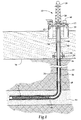
- a system for verifying the status of perforating guns prior to perforating a wellbore is operating from an offshore oil and gas platform that is schematically illustrated and generally designated 10.
- a semi-submersible platform 12 is centered over a submerged oil and gas formation 14 located below sea floor 16.
- a subsea conduit 18 extends from deck 20 of platform 12 to wellhead installation 22 including subsea blow-out preventers 24.
- Platform 12 has a hoisting apparatus 26 and a derrick 28 for raising and lowering pipe strings such as work sting 30.
- a wellbore 32 extends through the various earth strata including formation 14.
- a casing 34 is cemented within wellbore 32 by cement 36.
- Work string 30 includes various tools such as a plurality of perforating guns 38 disposed in a generally horizontal portion of wellbore 32 and a communication system including communication nodes 42, 44, 46, 48, 50.
- a surface communication node or controller 40 provides a user interface including, for example, input and output devices such as one or more video screens or monitors, including touch screens, one or more keyboards or keypads, one or more pointing or navigation devices, as well as any other user interface devices that are currently known to those skilled in the art or are developed.
- the user interface may take the form of a computer including a notebook computer.
- surface controller 40 may include a logic module having various controllers, processors, memory components, operating systems, instructions, communication protocols and the like for implementing the systems and methods for verifying the status of perforating guns of the present invention.
- Surface controller 40 is coupled to a bidirectional communication link that provides for communication between surface controller 40 and a node 42 that is positioned in the well as part of or attached to work string 30.
- the bidirectional communication link includes at least one communication path from surface controller 40 to node 42 and at least one communication path from node 42 to surface controller 40.
- bidirectional communication may be achieved via a half duplex channel which allows only one communication path to be open in any time period.
- bidirectional communication is achieved via a full duplex channel which allows simultaneous communication over multiple communication paths. This can be achieved, for example, by providing independent hardwire connections or over a shared physical media through frequency division duplexing, time division duplexing, echo cancellation or similar technique.
- the communication link may include one or more electrical conductors, optical conductors or other physical conductors.
- Each of communication nodes 42, 44, 46, 48, 50 includes a transmitter, a receiver and a logic module that includes, for example, various fixed logic circuits, controllers, processors, memory components, operating systems, instructions, communication protocols and the like for implementing the systems and methods for verifying the status of perforating guns of the present invention.
- each communication node 42, 44, 46, 48, 50 also includes a power supply such as a battery pack which may include a plurality of batteries, such as nickel cadmium, lithium, alkaline or other suitable power source, which are configured to provide proper operating voltage and current.
- communication nodes 42, 44, 46, 48, 50 are operable to transmit and receive acoustic signals that are propagated over work string 30.
- the transmitters and receivers of communication nodes 42, 44, 46, 48, 50 preferably include one or more transducers in the form of stacks of piezoelectric ceramic crystals. It should be noted that a single transducer may operated as both the transmitter and the receiver of a given communication node. Any number of communication nodes may be operated in the system of the present invention with the number determined by the length of work string 30, the noise in the wellbore, the type of communication media used and the like.
- communication nodes 44, 46, 48 serve as repeater that are positioned to receive the acoustic signals transmitted along work string 30 at a point where the acoustic signals are of a magnitude sufficient for adequate reception.
- the signals Once the acoustic signals reach a given node, the signals are converted to an electrical current which represents the information being transmitted and is fed to the logic module for processing. The current is then sent to the transducer to generate acoustic signals that are transmitted to the next node. In this manner, communication from node 40 to node 50 as well as from node 50 to node 40 is achieved.
- each perforating gun 38 may include one or more sensors such as moisture sensors, pressure sensors or other leak sensors.
- each of these sensors is individually addressable and communicates with communication node 50 via a wired connection but a short range wireless connection such as an electromagnetic communication link could alternatively be used.
- the commands are received by communication node 42 and retransmitted as encoded acoustic signals along work string 30 which are received by communication node 44.
- Communication node 44 acts as a repeater to receive, process and retransmit the commands via acoustic signals along work string 30 which are received by communication node 46.
- communication node 46 forwards the commands to communication node 48 via acoustic signals along work string 30 and communication node 48 forwards the commands to communication node 50 via acoustic signals along work string 30.
- Communication node 50 then sends the commands to interrogate each of the sensors in perforating guns 38.
- the sensors obtain the desired data regarding the leak status of each perforating gun 38 and provide this information to communication node 50.
- Communication node 50 converts this information to acoustic signals that are sent to communication node 48 along work string 30.
- Communication nodes 48, 46, 44 act as repeaters, each receiving, processing and retransmitting the information in the form of acoustic signals along work string 30.
- Communication node 42 receives the acoustic signals send from communication node 44 and processes the information such that it can be forwarded to surface controller 40 for analysis.
- the communication system may be used in a similar manner to enable, arm and fire perforating guns 38 using, for example, one or more electronic or hydraulic firing heads. Thereafter, the shaped charges within perforating guns 38 are sequentially fired, either in an uphole to downhole or a downhole to uphole direction. Upon detonation, the liners of the shaped charges form jets that create a spaced series of perforations extending outwardly through casing 34, cement 36 and into formation 14, thereby allow fluid communication between formation 14 and wellbore 32.
- wellbore 32 has an initial, generally vertical portion and a lower, generally deviated portion which is illustrated as being horizontal. It should be noted, however, by those skilled in the art that the system for verifying the status of perforating guns of the present invention is equally well-suited for use in other well configurations including, but not limited to, inclined wells, wells with restrictions, non-deviated wells and the like. In addition, even though figure 1 has been described with reference to an offshore environment, it should be understood by one skilled in the art that the principles described herein are equally well-suited for an onshore environment.
- logic module As should be understood by those skilled in the art, any of the functions described with reference to a logic module herein can be implemented using software, hardware, including fixed logic circuitry, manual processing or a combination of these implementations.
- the term “logic module” as used herein generally represents software, hardware or a combination of software and hardware.
- the term “logic module” represents program code and/or declarative content, e.g., markup language content, that performs specified tasks when executed on a processing device or devices such as one or more processors or CPUs.
- the program code can be stored in one or more computer readable memory devices.
- the functionality of the logic modules may be implemented as distinct units in separate physical grouping or can correspond to a conceptual allocation of different tasks performed by a single software program and/or hardware unit.
- the logic modules can be located at a single site such as implemented by a single processing device, or can be distributed over plural locations such as a notebook computer or personal digital assistant in combination with other physical devices that communication with one another via wired or wireless connections.
- Perforating gun 100 for use in the system for verifying the status of perforating guns of the present invention that is generally designated 100.
- Perforating gun 100 includes a carrier 102 having a plurality of recesses, such as recess 104, defined therein. Radially aligned with each of the recesses is a respective one of the plurality of shaped charges, such as shaped charge 106.
- the shaped charges are retained within carrier 102 by a support member 108 which includes an outer charge holder sleeve 110 and an inner charge holder sleeve 112.
- outer tube 110 supports the discharge ends of the shaped charges
- inner tube 112 supports the initiation ends of the shaped charges.
- Disposed within inner tube 112 is a detonating cord 116.
- the initiation ends of the shaped charges extend across the central longitudinal axis of perforating gun 100 allowing detonating cord 116 to connect to the high explosive within the shaped charges through an aperture defined at the apex of the housings of the shaped charges.
- carrier 102 is sealed to protect the shaped charges disposed therein against wellbore fluids.
- Each of the shaped charges such as shaped charge 106, is longitudinally and radially aligned with a recess, such as recess 104, in carrier 102 when perforating apparatus 100 is fully assembled.
- the shaped charges are arranged in a spiral pattern such that each shaped charge is disposed on its own level or height and is to be individually detonated so that only one shaped charge is fired at a time. It should be noted, however, by those skilled in the art that alternate arrangements of shaped charges may be used, including cluster type designs wherein more than one shaped charge is at the same level and is detonated at the same time, without departing from the principles of the present invention.
- perforating guns for use in the system for verifying the status of perforating guns of the present invention include one or more sensors used to obtain and provide information relative to environmental factors that surround perforating gun 100.
- perforating gun 100 includes a plurality of sensors such as sensor 120 positioned on the exterior of support member 108, sensor 122 positioned on the interior of support member 108, sensor 124 positioned on the interior of carrier 102 and sensor 126 positioned on the exterior of carrier 102.
- sensors 120, 122, 124, 126 are preferably coupled to communication node 50 via a wired connection but other communication means are also possible and considered within the scope of the present invention.
- Sensors 120, 122, 124, 126 may be of the same type or different types and may be moisture sensors, humidity sensors, pressure sensors including high speed pressure sensors or fast gauge sensors, temperature sensors, accelerometers, shock load sensors, liner displacement sensors, depth sensors, fluid sensors, CO 2 sensors, H 2 S sensors, CO sensors, thermal decomposition sensors, casing collar locators, gamma detectors or any other types of sensors that are operable to provide information relating to the perforating gun environment.
- Sensors 120, 122, 124, 126 and similar sensors associated with the perforating gun system may be used for monitoring a variety of environmental conditions relative to the gun string such as the depth and orientation of the guns in the wellbore; the condition of the guns prior to firing including leak status, pressure, thermal decomposition and moisture; whether the guns fired properly including gun pressures, accelerations and shock loads; the near wellbore reservoir parameters including temperatures, hydrostatic pressures, peak pressures and transient pressures as well as other environmental conditions that are known to those skilled in the art.
- the system of the present invention is operable to perform a variety of gun condition verifications such as those described above and including perforating gun depth and orientation verification and perforating guns condition verification. This verification is accomplished using the surface controller in conjunction with the communication nodes positioned along the work string to interrogate the sensors associated with the perforating guns for the desired information.
- an interrogation command requesting the leak status of one of the perforating guns is sent to one of the downhole sensors via the communication nodes and the work string and that downhole sensor responds with the requested information also via the communication nodes and the work string (step 204).
- the surface controller determines whether all the sensors have been interrogated (decision 206). If all of the sensors have not been interrogated, an interrogation command requesting the leak status of another of the perforating guns is sent to another of the downhole sensors and that downhole sensor responds with the requested information (step 208). This process continues until all of the sensors have been interrogated (decision 206).
- the surface controller determines whether all of the perforating guns are dry (decision 210). If all of the perforating guns are dry, the surface controller may proceed with the remainder of the firing sequence including sending the appropriate enable, arm and fire commands via the communication nodes to a suitable firing head (step 212). If all of the perforating guns are not dry, the surface controller determines whether remedial action can be taken to allow the perforating event to occur (decision 214). Such remedial action may include repeating the verification process to determine if the out of range condition persists, identifying which guns have an out of range condition and removing those guns from the firing sequence or the like. If in performing such remedial action the surface controller determines that the perforating event should occur, then the surface controller may proceed with the remainder of the firing sequence (step 212). If in performing such remedial action it is determined that the perforating event may not occur, then the process ends.
- the sensors associated with the perforating guns may continue gather and transmit information.
- sensors such as the above described accelerometers, pressure sensors, high speed pressure sensors, temperature sensors and the like are used to obtain a variety of perforating gun and near wellbore reservoir data.
- the high speed pressure sensors are operably to obtain pressure data in the millisecond range such that the pressure surge and associated pressure cycles created by the perforating event can be measured.
- the accelerometers are operable to record shock data associated with the perforating event. Use of this and other data provide for a determination of the intensity level of the detonation associated with the perforating guns. During, immediately after or at a later time, this information is communicated from the sensors to the surface controller over the communication system.
- This information may be used to determine the quality of the perforating event such as whether the initiator was detonated, whether any of the shaped charges within the perforating gun were detonated, whether all of the shaped charges within the perforating gun were detonated or whether only some of the shaped charges within the perforating gun were detonated. This information will allow the operator in substantially real time to determine, for example, if a zone should be reperforated.
- the sensors associated with the perforating guns may continue gather and transmit information.
- sensors such as the above described pressure sensors, temperature sensors, fluid sensors and the like are used to obtain a variety of near wellbore reservoir data. This data may be useful in designing the next phase of the completion such as whether to perform an acid job or a facture stimulation.
Applications Claiming Priority (1)
| Application Number | Priority Date | Filing Date | Title |
|---|---|---|---|
| US12/327,019 US20100133004A1 (en) | 2008-12-03 | 2008-12-03 | System and Method for Verifying Perforating Gun Status Prior to Perforating a Wellbore |
Publications (1)
| Publication Number | Publication Date |
|---|---|
| EP2194227A2 true EP2194227A2 (fr) | 2010-06-09 |
Family
ID=41718521
Family Applications (1)
| Application Number | Title | Priority Date | Filing Date |
|---|---|---|---|
| EP09176479A Withdrawn EP2194227A2 (fr) | 2008-12-03 | 2009-11-19 | Système et procédé pour vérifier l'état d'un canon perforateur avant de perforer un trou de forage |
Country Status (6)
| Country | Link |
|---|---|
| US (1) | US20100133004A1 (fr) |
| EP (1) | EP2194227A2 (fr) |
| AU (1) | AU2009236038A1 (fr) |
| BR (1) | BRPI0905283A2 (fr) |
| CA (1) | CA2686290A1 (fr) |
| MX (1) | MX2009012791A (fr) |
Cited By (7)
| Publication number | Priority date | Publication date | Assignee | Title |
|---|---|---|---|---|
| WO2014090633A1 (fr) * | 2012-12-13 | 2014-06-19 | Wintershall Holding GmbH | Dispositif et procédé de stimulation et de nettoyage d'un trou de forage rempli de liquide |
| CN105051325A (zh) * | 2012-10-17 | 2015-11-11 | 越洋创新实验室有限公司 | 用于海底处理器的通信系统和方法 |
| WO2016048457A1 (fr) * | 2014-09-26 | 2016-03-31 | Exxonmobil Upstream Research Company | Systèmes et procédés pour surveiller un état d'un élément tubulaire conçu pour transporter un fluide d'hydrocarbure |
| EP2741427A3 (fr) * | 2012-12-04 | 2016-12-21 | Schlumberger Technology B.V. | Système et procédé de forage destiné à de multiples fréquences de porteuse, télémétrie de câble semi-duplex |
| GB2546061A (en) * | 2015-10-12 | 2017-07-12 | Silixa Ltd | Method and system for downhole object location and orientation determination |
| EP3049613A4 (fr) * | 2013-09-27 | 2017-11-15 | Transocean Innovation Labs Ltd | Systèmes de commande et/ou d'alimentation électrique et/ou de communication de données pour des blocs obturateurs de puits et procédés associés |
| US10982512B1 (en) | 2019-10-18 | 2021-04-20 | Halliburton Energy Services, Inc. | Assessing a downhole state of perforating explosives |
Families Citing this family (51)
| Publication number | Priority date | Publication date | Assignee | Title |
|---|---|---|---|---|
| US7980309B2 (en) * | 2008-04-30 | 2011-07-19 | Halliburton Energy Services, Inc. | Method for selective activation of downhole devices in a tool string |
| EP2649274A1 (fr) * | 2010-12-10 | 2013-10-16 | Services Pétroliers Schlumberger | Système et procédé pour enregistrement acoustique dans un ensemble en fond de puits durant l'utilisation d'un perforateur |
| US8397814B2 (en) | 2010-12-17 | 2013-03-19 | Halliburton Energy Serivces, Inc. | Perforating string with bending shock de-coupler |
| US8985200B2 (en) * | 2010-12-17 | 2015-03-24 | Halliburton Energy Services, Inc. | Sensing shock during well perforating |
| EP2652264A4 (fr) * | 2010-12-17 | 2015-05-06 | Halliburton Energy Services Inc | Perforation de puits à détermination de caractéristiques de puits |
| US8397800B2 (en) | 2010-12-17 | 2013-03-19 | Halliburton Energy Services, Inc. | Perforating string with longitudinal shock de-coupler |
| US8393393B2 (en) | 2010-12-17 | 2013-03-12 | Halliburton Energy Services, Inc. | Coupler compliance tuning for mitigating shock produced by well perforating |
| EP2670948B1 (fr) * | 2011-02-03 | 2017-05-31 | Baker Hughes Incorporated | Dispositif pour vérifier une connexion de détonateur |
| US20120241169A1 (en) | 2011-03-22 | 2012-09-27 | Halliburton Energy Services, Inc. | Well tool assemblies with quick connectors and shock mitigating capabilities |
| US8881816B2 (en) | 2011-04-29 | 2014-11-11 | Halliburton Energy Services, Inc. | Shock load mitigation in a downhole perforation tool assembly |
| US9091152B2 (en) | 2011-08-31 | 2015-07-28 | Halliburton Energy Services, Inc. | Perforating gun with internal shock mitigation |
| US8844625B2 (en) * | 2011-11-01 | 2014-09-30 | Baker Hughes Incorporated | Perforating gun spacer |
| WO2013130092A1 (fr) * | 2012-03-02 | 2013-09-06 | Halliburton Energy Services, Inc. | Appareil de perforation et méthode présentant un chemin de charge interne |
| US9297228B2 (en) | 2012-04-03 | 2016-03-29 | Halliburton Energy Services, Inc. | Shock attenuator for gun system |
| US9598940B2 (en) | 2012-09-19 | 2017-03-21 | Halliburton Energy Services, Inc. | Perforation gun string energy propagation management system and methods |
| US8978749B2 (en) | 2012-09-19 | 2015-03-17 | Halliburton Energy Services, Inc. | Perforation gun string energy propagation management with tuned mass damper |
| US9523271B2 (en) | 2012-09-21 | 2016-12-20 | Halliburton Energy Services, Inc. | Wireless communication for downhole tool strings |
| WO2014084868A1 (fr) | 2012-12-01 | 2014-06-05 | Halliburton Energy Services, Inc. | Protection des dispositifs électroniques utilisés avec les perforateurs de tubage |
| US10508536B2 (en) | 2014-09-12 | 2019-12-17 | Exxonmobil Upstream Research Company | Discrete wellbore devices, hydrocarbon wells including a downhole communication network and the discrete wellbore devices and systems and methods including the same |
| CN107109926A (zh) * | 2015-01-19 | 2017-08-29 | 哈利伯顿能源服务公司 | 具有多种通信模式的井下声学遥测模块 |
| US10408047B2 (en) | 2015-01-26 | 2019-09-10 | Exxonmobil Upstream Research Company | Real-time well surveillance using a wireless network and an in-wellbore tool |
| US10465505B2 (en) | 2016-08-30 | 2019-11-05 | Exxonmobil Upstream Research Company | Reservoir formation characterization using a downhole wireless network |
| US10590759B2 (en) | 2016-08-30 | 2020-03-17 | Exxonmobil Upstream Research Company | Zonal isolation devices including sensing and wireless telemetry and methods of utilizing the same |
| US10697287B2 (en) | 2016-08-30 | 2020-06-30 | Exxonmobil Upstream Research Company | Plunger lift monitoring via a downhole wireless network field |
| US11828172B2 (en) | 2016-08-30 | 2023-11-28 | ExxonMobil Technology and Engineering Company | Communication networks, relay nodes for communication networks, and methods of transmitting data among a plurality of relay nodes |
| US10344583B2 (en) | 2016-08-30 | 2019-07-09 | Exxonmobil Upstream Research Company | Acoustic housing for tubulars |
| US10526888B2 (en) | 2016-08-30 | 2020-01-07 | Exxonmobil Upstream Research Company | Downhole multiphase flow sensing methods |
| US10415376B2 (en) | 2016-08-30 | 2019-09-17 | Exxonmobil Upstream Research Company | Dual transducer communications node for downhole acoustic wireless networks and method employing same |
| US10364669B2 (en) | 2016-08-30 | 2019-07-30 | Exxonmobil Upstream Research Company | Methods of acoustically communicating and wells that utilize the methods |
| US11199075B2 (en) * | 2016-12-30 | 2021-12-14 | Metrol Technology Ltd. | Downhole energy harvesting |
| WO2018122545A1 (fr) * | 2016-12-30 | 2018-07-05 | Metrol Technology Ltd | Dispositif de récupération d'énergie en fond de trou |
| DE112017007457T5 (de) * | 2017-04-19 | 2020-01-02 | Halliburton Energy Services, Inc. | System und Verfahren, um Bohrlochdruck während des Perforierens zu steuern |
| US10837276B2 (en) | 2017-10-13 | 2020-11-17 | Exxonmobil Upstream Research Company | Method and system for performing wireless ultrasonic communications along a drilling string |
| CN111201727B (zh) | 2017-10-13 | 2021-09-03 | 埃克森美孚上游研究公司 | 利用混合通信网络进行烃操作的方法和系统 |
| CN111201755B (zh) | 2017-10-13 | 2022-11-15 | 埃克森美孚上游研究公司 | 使用通信执行操作的方法和系统 |
| US11035226B2 (en) | 2017-10-13 | 2021-06-15 | Exxomobil Upstream Research Company | Method and system for performing operations with communications |
| WO2019074656A1 (fr) | 2017-10-13 | 2019-04-18 | Exxonmobil Upstream Research Company | Procédé et système pour permettre des communications en utilisant le repliement |
| US10697288B2 (en) | 2017-10-13 | 2020-06-30 | Exxonmobil Upstream Research Company | Dual transducer communications node including piezo pre-tensioning for acoustic wireless networks and method employing same |
| US11203927B2 (en) | 2017-11-17 | 2021-12-21 | Exxonmobil Upstream Research Company | Method and system for performing wireless ultrasonic communications along tubular members |
| US10690794B2 (en) | 2017-11-17 | 2020-06-23 | Exxonmobil Upstream Research Company | Method and system for performing operations using communications for a hydrocarbon system |
| US10844708B2 (en) | 2017-12-20 | 2020-11-24 | Exxonmobil Upstream Research Company | Energy efficient method of retrieving wireless networked sensor data |
| US11156081B2 (en) | 2017-12-29 | 2021-10-26 | Exxonmobil Upstream Research Company | Methods and systems for operating and maintaining a downhole wireless network |
| CN111542679A (zh) | 2017-12-29 | 2020-08-14 | 埃克森美孚上游研究公司 | 用于监视和优化储层增产操作的方法和系统 |
| WO2019156966A1 (fr) | 2018-02-08 | 2019-08-15 | Exxonmobil Upstream Research Company | Procédés d'identification homologue de réseau et d'auto-organisation à l'aide de signatures tonales uniques et puits qui utilisent les procédés |
| US11268378B2 (en) | 2018-02-09 | 2022-03-08 | Exxonmobil Upstream Research Company | Downhole wireless communication node and sensor/tools interface |
| US10669821B2 (en) * | 2018-04-25 | 2020-06-02 | G&H Diversified Manufacturing Lp | Charge tube assembly |
| WO2020058098A1 (fr) | 2018-09-17 | 2020-03-26 | DynaEnergetics Europe GmbH | Outil d'inspection pour un segment de perforateur |
| US11293280B2 (en) | 2018-12-19 | 2022-04-05 | Exxonmobil Upstream Research Company | Method and system for monitoring post-stimulation operations through acoustic wireless sensor network |
| US11952886B2 (en) | 2018-12-19 | 2024-04-09 | ExxonMobil Technology and Engineering Company | Method and system for monitoring sand production through acoustic wireless sensor network |
| GB2596485B (en) * | 2019-06-10 | 2023-05-03 | Halliburton Energy Services Inc | Oriented detection perforating device |
| US11346214B2 (en) | 2019-09-13 | 2022-05-31 | Baker Hughes Oilfield Operations Llc | Monitoring of downhole components during deployment |
Family Cites Families (72)
| Publication number | Priority date | Publication date | Assignee | Title |
|---|---|---|---|---|
| US2810546A (en) * | 1952-03-25 | 1957-10-22 | Physics Corp | Drill tool telemetering systems |
| US3205477A (en) * | 1961-12-29 | 1965-09-07 | David C Kalbfell | Electroacoustical logging while drilling wells |
| US3697940A (en) * | 1968-08-23 | 1972-10-10 | Bohdan Jiri Berka | Signalling system for bore logging |
| US3588804A (en) * | 1969-06-16 | 1971-06-28 | Globe Universal Sciences | Telemetering system for use in boreholes |
| US3889228A (en) * | 1973-11-16 | 1975-06-10 | Sun Oil Co | Two-way acoustic telemetering system |
| US4066995A (en) * | 1975-01-12 | 1978-01-03 | Sperry Rand Corporation | Acoustic isolation for a telemetry system on a drill string |
| US4293936A (en) * | 1976-12-30 | 1981-10-06 | Sperry-Sun, Inc. | Telemetry system |
| US4156229A (en) * | 1977-01-31 | 1979-05-22 | Sperry-Sun, Inc. | Bit identification system for borehole acoustical telemetry system |
| US4390975A (en) * | 1978-03-20 | 1983-06-28 | Nl Sperry-Sun, Inc. | Data transmission in a drill string |
| US4206810A (en) * | 1978-06-20 | 1980-06-10 | Halliburton Company | Method and apparatus for indicating the downhole arrival of a well tool |
| US4320473A (en) * | 1979-08-10 | 1982-03-16 | Sperry Sun, Inc. | Borehole acoustic telemetry clock synchronization system |
| US4298970A (en) * | 1979-08-10 | 1981-11-03 | Sperry-Sun, Inc. | Borehole acoustic telemetry system synchronous detector |
| US4293937A (en) * | 1979-08-10 | 1981-10-06 | Sperry-Sun, Inc. | Borehole acoustic telemetry system |
| US4254481A (en) * | 1979-08-10 | 1981-03-03 | Sperry-Sun, Inc. | Borehole telemetry system automatic gain control |
| US4314365A (en) * | 1980-01-21 | 1982-02-02 | Exxon Production Research Company | Acoustic transmitter and method to produce essentially longitudinal, acoustic waves |
| US4302826A (en) * | 1980-01-21 | 1981-11-24 | Sperry Corporation | Resonant acoustic transducer system for a well drilling string |
| US4283780A (en) * | 1980-01-21 | 1981-08-11 | Sperry Corporation | Resonant acoustic transducer system for a well drilling string |
| US4562559A (en) * | 1981-01-19 | 1985-12-31 | Nl Sperry Sun, Inc. | Borehole acoustic telemetry system with phase shifted signal |
| US4908804A (en) * | 1983-03-21 | 1990-03-13 | Develco, Inc. | Combinatorial coded telemetry in MWD |
| US5128901A (en) * | 1988-04-21 | 1992-07-07 | Teleco Oilfield Services Inc. | Acoustic data transmission through a drillstring |
| GB9021253D0 (en) * | 1990-09-29 | 1990-11-14 | Metrol Tech Ltd | Method of and apparatus for the transmission of data via a sonic signal |
| US5148408A (en) * | 1990-11-05 | 1992-09-15 | Teleco Oilfield Services Inc. | Acoustic data transmission method |
| US5050132A (en) * | 1990-11-07 | 1991-09-17 | Teleco Oilfield Services Inc. | Acoustic data transmission method |
| JP3311484B2 (ja) * | 1994-04-25 | 2002-08-05 | 三菱電機株式会社 | 信号伝送装置及び信号伝送方法 |
| US5124953A (en) * | 1991-07-26 | 1992-06-23 | Teleco Oilfield Services Inc. | Acoustic data transmission method |
| EP0552833B1 (fr) * | 1992-01-21 | 1996-11-06 | Anadrill International SA | Système de télémétrie avec vibrations sonores |
| NO305219B1 (no) * | 1994-03-16 | 1999-04-19 | Aker Eng As | FremgangsmÕte og sender/mottaker for overf°ring av signaler via et medium i r°r eller slanger |
| US5586083A (en) * | 1994-08-25 | 1996-12-17 | Harriburton Company | Turbo siren signal generator for measurement while drilling systems |
| US5477505A (en) * | 1994-09-09 | 1995-12-19 | Sandia Corporation | Downhole pipe selection for acoustic telemetry |
| US6442105B1 (en) * | 1995-02-09 | 2002-08-27 | Baker Hughes Incorporated | Acoustic transmission system |
| US5732776A (en) * | 1995-02-09 | 1998-03-31 | Baker Hughes Incorporated | Downhole production well control system and method |
| US5675325A (en) * | 1995-10-20 | 1997-10-07 | Japan National Oil Corporation | Information transmitting apparatus using tube body |
| US5995449A (en) * | 1995-10-20 | 1999-11-30 | Baker Hughes Inc. | Method and apparatus for improved communication in a wellbore utilizing acoustic signals |
| GB9607297D0 (en) * | 1996-04-09 | 1996-06-12 | Anadrill Int Sa | Noise detection and suppression system for wellbore telemetry |
| US5924499A (en) * | 1997-04-21 | 1999-07-20 | Halliburton Energy Services, Inc. | Acoustic data link and formation property sensor for downhole MWD system |
| GB2327957A (en) * | 1997-08-09 | 1999-02-10 | Anadrill Int Sa | Method and apparatus for suppressing drillstring vibrations |
| US6137747A (en) * | 1998-05-29 | 2000-10-24 | Halliburton Energy Services, Inc. | Single point contact acoustic transmitter |
| JP2000121742A (ja) * | 1998-10-14 | 2000-04-28 | Mitsubishi Electric Corp | 掘削管体音響伝送用送信機およびこの送信機による掘削管体音響伝送方法 |
| US7383882B2 (en) * | 1998-10-27 | 2008-06-10 | Schlumberger Technology Corporation | Interactive and/or secure activation of a tool |
| US6175316B1 (en) * | 1999-04-07 | 2001-01-16 | Legerity | Bin-to-bin differential encoding apparatus and method for a discrete multi-tone transmission system |
| US6386288B1 (en) * | 1999-04-27 | 2002-05-14 | Marathon Oil Company | Casing conveyed perforating process and apparatus |
| US6370082B1 (en) * | 1999-06-14 | 2002-04-09 | Halliburton Energy Services, Inc. | Acoustic telemetry system with drilling noise cancellation |
| US6320820B1 (en) * | 1999-09-20 | 2001-11-20 | Halliburton Energy Services, Inc. | High data rate acoustic telemetry system |
| US6434084B1 (en) * | 1999-11-22 | 2002-08-13 | Halliburton Energy Services, Inc. | Adaptive acoustic channel equalizer & tuning method |
| US6583729B1 (en) * | 2000-02-21 | 2003-06-24 | Halliburton Energy Services, Inc. | High data rate acoustic telemetry system using multipulse block signaling with a minimum distance receiver |
| US6348876B1 (en) * | 2000-06-22 | 2002-02-19 | Halliburton Energy Services, Inc. | Burst QAM downhole telemetry system |
| US6557636B2 (en) * | 2001-06-29 | 2003-05-06 | Shell Oil Company | Method and apparatus for perforating a well |
| US6933856B2 (en) * | 2001-08-02 | 2005-08-23 | Halliburton Energy Services, Inc. | Adaptive acoustic transmitter controller apparatus and method |
| US6940420B2 (en) * | 2001-12-18 | 2005-09-06 | Schlumberger Technology Corporation | Drill string telemetry system |
| US6909667B2 (en) * | 2002-02-13 | 2005-06-21 | Halliburton Energy Services, Inc. | Dual channel downhole telemetry |
| US6880634B2 (en) * | 2002-12-03 | 2005-04-19 | Halliburton Energy Services, Inc. | Coiled tubing acoustic telemetry system and method |
| US7163065B2 (en) * | 2002-12-06 | 2007-01-16 | Shell Oil Company | Combined telemetry system and method |
| US6962202B2 (en) * | 2003-01-09 | 2005-11-08 | Shell Oil Company | Casing conveyed well perforating apparatus and method |
| US7234519B2 (en) * | 2003-04-08 | 2007-06-26 | Halliburton Energy Services, Inc. | Flexible piezoelectric for downhole sensing, actuation and health monitoring |
| US7150317B2 (en) * | 2004-03-17 | 2006-12-19 | Baker Hughes Incorporated | Use of electromagnetic acoustic transducers in downhole cement evaluation |
| US7273102B2 (en) * | 2004-05-28 | 2007-09-25 | Schlumberger Technology Corporation | Remotely actuating a casing conveyed tool |
| US7339494B2 (en) * | 2004-07-01 | 2008-03-04 | Halliburton Energy Services, Inc. | Acoustic telemetry transceiver |
| US7249636B2 (en) * | 2004-12-09 | 2007-07-31 | Schlumberger Technology Corporation | System and method for communicating along a wellbore |
| US7590029B2 (en) * | 2005-02-24 | 2009-09-15 | The Charles Stark Draper Laboratory, Inc. | Methods and systems for communicating data through a pipe |
| US7624681B2 (en) * | 2005-05-06 | 2009-12-01 | Schlumberger Technology Corporation | Initiator activated by a stimulus |
| US20070168132A1 (en) * | 2005-05-06 | 2007-07-19 | Schlumberger Technology Corporation | Wellbore communication system and method |
| US8004421B2 (en) * | 2006-05-10 | 2011-08-23 | Schlumberger Technology Corporation | Wellbore telemetry and noise cancellation systems and method for the same |
| US8044821B2 (en) * | 2005-09-12 | 2011-10-25 | Schlumberger Technology Corporation | Downhole data transmission apparatus and methods |
| US9109439B2 (en) * | 2005-09-16 | 2015-08-18 | Intelliserv, Llc | Wellbore telemetry system and method |
| US7694745B2 (en) * | 2005-09-16 | 2010-04-13 | Halliburton Energy Services, Inc. | Modular well tool system |
| WO2007095111A1 (fr) * | 2006-02-14 | 2007-08-23 | Baker Hughes Incorporated | Système et procédé de télémétrie pendant le forage |
| US7768423B2 (en) * | 2006-04-11 | 2010-08-03 | XAct Dowhole Telemetry Inc. | Telemetry transmitter optimization via inferred measured depth |
| US20070257809A1 (en) * | 2006-04-11 | 2007-11-08 | Xact Downhole Telemetry Inc. | Acoustic telemetry system optimization |
| US7928861B2 (en) * | 2006-04-19 | 2011-04-19 | Xact Downhole Telemetry Inc. | Telemetry wave detection apparatus and method |
| US7557492B2 (en) * | 2006-07-24 | 2009-07-07 | Halliburton Energy Services, Inc. | Thermal expansion matching for acoustic telemetry system |
| US7595737B2 (en) * | 2006-07-24 | 2009-09-29 | Halliburton Energy Services, Inc. | Shear coupled acoustic telemetry system |
| US8157022B2 (en) * | 2007-09-28 | 2012-04-17 | Schlumberger Technology Corporation | Apparatus string for use in a wellbore |
-
2008
- 2008-12-03 US US12/327,019 patent/US20100133004A1/en not_active Abandoned
-
2009
- 2009-11-12 AU AU2009236038A patent/AU2009236038A1/en not_active Abandoned
- 2009-11-19 EP EP09176479A patent/EP2194227A2/fr not_active Withdrawn
- 2009-11-25 CA CA2686290A patent/CA2686290A1/fr not_active Abandoned
- 2009-11-25 MX MX2009012791A patent/MX2009012791A/es not_active Application Discontinuation
- 2009-12-03 BR BRPI0905283-6A patent/BRPI0905283A2/pt not_active Application Discontinuation
Cited By (16)
| Publication number | Priority date | Publication date | Assignee | Title |
|---|---|---|---|---|
| CN105051325B (zh) * | 2012-10-17 | 2019-01-22 | 越洋创新实验室有限公司 | 用于海底处理器的通信系统和方法 |
| CN105051325A (zh) * | 2012-10-17 | 2015-11-11 | 越洋创新实验室有限公司 | 用于海底处理器的通信系统和方法 |
| US10539010B2 (en) | 2012-10-17 | 2020-01-21 | Transocean Innovation Labs Ltd. | Subsea processor for underwater drilling operations |
| EP2909436A4 (fr) * | 2012-10-17 | 2016-08-24 | Transocean Innovation Labs Ltd | Systèmes et procédés de communication pour des processeurs sous-marins |
| EP2741427A3 (fr) * | 2012-12-04 | 2016-12-21 | Schlumberger Technology B.V. | Système et procédé de forage destiné à de multiples fréquences de porteuse, télémétrie de câble semi-duplex |
| US10601464B2 (en) | 2012-12-04 | 2020-03-24 | Schlumberger Technology Corporation | Wellsite system and method for multiple carrier frequency, half duplex cable telemetry |
| WO2014090633A1 (fr) * | 2012-12-13 | 2014-06-19 | Wintershall Holding GmbH | Dispositif et procédé de stimulation et de nettoyage d'un trou de forage rempli de liquide |
| EP3049613A4 (fr) * | 2013-09-27 | 2017-11-15 | Transocean Innovation Labs Ltd | Systèmes de commande et/ou d'alimentation électrique et/ou de communication de données pour des blocs obturateurs de puits et procédés associés |
| US9879525B2 (en) | 2014-09-26 | 2018-01-30 | Exxonmobil Upstream Research Company | Systems and methods for monitoring a condition of a tubular configured to convey a hydrocarbon fluid |
| WO2016048457A1 (fr) * | 2014-09-26 | 2016-03-31 | Exxonmobil Upstream Research Company | Systèmes et procédés pour surveiller un état d'un élément tubulaire conçu pour transporter un fluide d'hydrocarbure |
| GB2546061A (en) * | 2015-10-12 | 2017-07-12 | Silixa Ltd | Method and system for downhole object location and orientation determination |
| GB2546061B (en) * | 2015-10-12 | 2021-10-13 | Silixa Ltd | Method and system for downhole object location and orientation determination |
| US10982512B1 (en) | 2019-10-18 | 2021-04-20 | Halliburton Energy Services, Inc. | Assessing a downhole state of perforating explosives |
| WO2021076155A1 (fr) * | 2019-10-18 | 2021-04-22 | Halliburton Energy Services, Inc. | Évaluation d'un état de fond de trou d'explosifs perforants |
| GB2603313A (en) * | 2019-10-18 | 2022-08-03 | Halliburton Energy Services Inc | Assessing a downhole state of perforating explosives |
| GB2603313B (en) * | 2019-10-18 | 2023-08-02 | Halliburton Energy Services Inc | Assessing a downhole state of perforating explosives |
Also Published As
| Publication number | Publication date |
|---|---|
| AU2009236038A1 (en) | 2010-06-17 |
| MX2009012791A (es) | 2010-06-21 |
| CA2686290A1 (fr) | 2010-06-03 |
| US20100133004A1 (en) | 2010-06-03 |
| BRPI0905283A2 (pt) | 2011-03-22 |
Similar Documents
| Publication | Publication Date | Title |
|---|---|---|
| EP2194227A2 (fr) | Système et procédé pour vérifier l'état d'un canon perforateur avant de perforer un trou de forage | |
| US8672031B2 (en) | Perforating with wired drill pipe | |
| US10490054B2 (en) | In-line integrity checker | |
| EP1853792B1 (fr) | Dispositif et procede de declenchement de perforateurs | |
| RU2493358C2 (ru) | Беспроводное инициирование скважинного перфоратора | |
| US7228902B2 (en) | High data rate borehole telemetry system | |
| EP2157278A1 (fr) | Systèmes télémétriques sans fil pour outils d'extraction | |
| EP2157279A1 (fr) | Synchronisation de transmetteur et de récepteur pour le domaine technique de la télémétrie sans fil | |
| EP1965021A2 (fr) | Procédé de collecte de données géologiques | |
| CN111527283B (zh) | 用于操作和维护井下无线网络的方法和系统 | |
| US11286756B2 (en) | Slickline selective perforation system | |
| MX2013001565A (es) | Controles automatizados para operaciones de bombeo descendente. | |
| WO2017105434A1 (fr) | Atténuation de dommage de câble pendant une perforation | |
| CN106574497A (zh) | 钻机遥测系统 | |
| US8022839B2 (en) | Telemetry subsystem to communicate with plural downhole modules | |
| NO325161B1 (no) | Fremgangsmåte og anordning for å bestemme brønndybde under brønnoperasjoner ved hjelp av radiofrekvens- identifikasjonsinnretninger | |
| NO342981B1 (no) | Reservoarovervåkingssystem, samt fremgangsmåte | |
| US11513247B2 (en) | Data acquisition systems | |
| US11377937B2 (en) | System, method, and device for monitoring a parameter downhole | |
| WO2022081017A1 (fr) | Dispositif et procédé de surveillance d'espace annulaire b de rénovation | |
| GB2605061A (en) | Retrofit B annulus monitoring device and method |
Legal Events
| Date | Code | Title | Description |
|---|---|---|---|
| PUAI | Public reference made under article 153(3) epc to a published international application that has entered the european phase |
Free format text: ORIGINAL CODE: 0009012 |
|
| AK | Designated contracting states |
Kind code of ref document: A2 Designated state(s): AT BE BG CH CY CZ DE DK EE ES FI FR GB GR HR HU IE IS IT LI LT LU LV MC MK MT NL NO PL PT RO SE SI SK SM TR |
|
| AX | Request for extension of the european patent |
Extension state: AL BA RS |
|
| STAA | Information on the status of an ep patent application or granted ep patent |
Free format text: STATUS: THE APPLICATION IS DEEMED TO BE WITHDRAWN |
|
| 18D | Application deemed to be withdrawn |
Effective date: 20120601 |