EP2194226A1 - Apparatus and Method for Deploying Cementing Plugs - Google Patents
Apparatus and Method for Deploying Cementing Plugs Download PDFInfo
- Publication number
- EP2194226A1 EP2194226A1 EP08170646A EP08170646A EP2194226A1 EP 2194226 A1 EP2194226 A1 EP 2194226A1 EP 08170646 A EP08170646 A EP 08170646A EP 08170646 A EP08170646 A EP 08170646A EP 2194226 A1 EP2194226 A1 EP 2194226A1
- Authority
- EP
- European Patent Office
- Prior art keywords
- plug
- sleeve
- basket
- dart
- cement
- Prior art date
- Legal status (The legal status is an assumption and is not a legal conclusion. Google has not performed a legal analysis and makes no representation as to the accuracy of the status listed.)
- Withdrawn
Links
- 238000000034 method Methods 0.000 title claims description 11
- 239000004568 cement Substances 0.000 claims abstract description 69
- 230000001681 protective effect Effects 0.000 claims abstract description 40
- 230000015572 biosynthetic process Effects 0.000 claims abstract description 22
- 238000005755 formation reaction Methods 0.000 claims abstract description 22
- 238000005086 pumping Methods 0.000 claims description 10
- 230000000717 retained effect Effects 0.000 claims description 6
- 239000012858 resilient material Substances 0.000 claims description 2
- 239000012781 shape memory material Substances 0.000 claims description 2
- 239000012530 fluid Substances 0.000 description 18
- 238000005553 drilling Methods 0.000 description 10
- 230000008901 benefit Effects 0.000 description 2
- 230000003247 decreasing effect Effects 0.000 description 2
- 230000003628 erosive effect Effects 0.000 description 2
- 230000005484 gravity Effects 0.000 description 2
- 230000002706 hydrostatic effect Effects 0.000 description 2
- 230000008569 process Effects 0.000 description 2
- 238000005299 abrasion Methods 0.000 description 1
- 230000008859 change Effects 0.000 description 1
- 230000001010 compromised effect Effects 0.000 description 1
- 238000010276 construction Methods 0.000 description 1
- 230000006870 function Effects 0.000 description 1
- 230000000670 limiting effect Effects 0.000 description 1
- 230000007246 mechanism Effects 0.000 description 1
- 239000007787 solid Substances 0.000 description 1
Images


Classifications
-
- E—FIXED CONSTRUCTIONS
- E21—EARTH DRILLING; MINING
- E21B—EARTH DRILLING, e.g. DEEP DRILLING; OBTAINING OIL, GAS, WATER, SOLUBLE OR MELTABLE MATERIALS OR A SLURRY OF MINERALS FROM WELLS
- E21B33/00—Sealing or packing boreholes or wells
- E21B33/10—Sealing or packing boreholes or wells in the borehole
- E21B33/13—Methods or devices for cementing, for plugging holes, crevices, or the like
- E21B33/14—Methods or devices for cementing, for plugging holes, crevices, or the like for cementing casings into boreholes
- E21B33/16—Methods or devices for cementing, for plugging holes, crevices, or the like for cementing casings into boreholes using plugs for isolating cement charge; Plugs therefor
- E21B33/165—Cementing plugs specially adapted for being released down-hole
Definitions
- This invention relates to apparatus and methods for use in cementing operations in wells such as oil and gas wells.
- the invention relates to apparatus as methods for deploying cementing plugs used such operations.
- the drilling fluid In conventional well drilling operations such as those used for drilling oil and gas wells, the drilling fluid, sometime called 'drilling mud', is circulated down the well through the tubular drill pipe used to carry the bit and back to the surface to carry debris away from the drill bit.
- the hydrostatic pressure of the drilling fluid column also provides mechanical and physical support to the borehole wall and prevents fluid mixing between subterranean layers in the formation by providing a pressure balance.
- the hydrostatic pressure imposed by the drilling fluid column at the bottom of the borehole increases and may surpass the fracture pressure of the formation which can lead to damage while decreasing the density of the drilling fluid to avoid this may in turn mean that it is no longer possible to provide pressure balance at shallower depths in the borehole.
- a continuous casing formed by a number of tubular sections joined end to end, is lowered into the well and cement is pumped down the inside of the casing to exit at its lower end and fill the annulus formed between the outside of the casing and the borehole wall where it is allowed to set.
- drilling can be restarted in the usual way and the cement casing provides the physical and mechanical support for the top part of the formation that was previously drilled.
- Figures 1 and 2 show an example of a known apparatus for deploying such cement plugs.
- the apparatus comprises a tubular basket 20 that is located at one end at the end of a drill pipe 12 that is used for delivery of cement and is open at the other end.
- the outer diameter of basket 20 is larger than the drill pipe and houses cementing plugs 18, 22.
- each plug has an opening at its lower end that is smaller than the inner diameter of the drill pipe 12.
- the opening of the lower plug 22 is in turn smaller than the corresponding opening in the plug above 18.
- the openings in the cement plugs 18, 22 allow for fluid flow therethrough.
- the limited size of the openings is a limiting factor for pumping fluids at a high flow rate.
- Deployment of the plugs 18, 22 is achieved by pumping darts 10, 14 from the surface through the drill pipe 12.
- the darts 10, 14 seat in the openings of the plugs 18, 22 so as to block fluid flow and the pressure caused by this blockage causes the plug to be driven from the basket 20 (see Figure 2 ).
- the bottom dart 14 has a smaller profile than that of upper dart 10 in order to be able to pass through opening in the upper cement plug 18 to seat in the opening of the lower plug 22.
- the number of cement plugs that can be loaded into the basket is limited due to the need for a constantly decreasing inner diameter of the opening in each consecutive cement plug. In the current state of the art, two cement plugs per basket is the limit.
- a first aspect of this invention provides an apparatus for installing cement plugs into a well, comprising a protective sleeve having one end adapted to be attached to the end of a drill pipe and arranged to carry a cementing plug around its outer surface such that a dart passing through the drill pipe can pass through the sleeve and engage only on formations on the plug to withdraw it from the end of the sleeve.
- the apparatus preferably comprises a tubular basket having one end adapted to be attached to the end of a drill pipe and being open at the other end, the basket defining a receptacle in which a cementing plug can be retained such that a dart passing through the drill pipe can engage on formations on the plug to withdraw it from the basket through the open end; wherein the apparatus further comprises a protective sleeve extending through the interior of the basket from the end to be attached to the drill pipe so as to define an annular chamber in which the cement plug can be retained such that the dart can pass through the protective sleeve and only engage the plug by means of the formations at the open end.
- the basket is typically sized to accommodate more than one cementing plug (two or three being preferred) positioned one above the other, the formations on only the lowermost extending inwards of the sleeve diameter so as to be engageable by a dart.
- the protective sleeve can be arranged to rupture as the lowermost cementing plug is withdrawn from the basket so that the formations of the cementing plug immediately above are allowed to project inwardly of the new end of the protective sleeve.
- the protective sleeve typically has substantially the same internal diameter as the drill pipe.
- a preferred form of the apparatus has at least one cementing plug retained in the basket such that formations on the plug project radially inwardly of the end of the protective sleeve so as to be engageable by a dart.
- each cementing plug is formed with a section of the protective sleeve which detaches from the apparatus as the plug is withdrawn from the basket.
- the formations on the cement plug typically comprise a resiliently deformable section that deforms inwardly when not supported in the sleeve.
- the resiliently deformable section can comprise at least one finger, and can also comprise a shape memory material, or a pivotable member that is biased inwardly by a resilient material such as rubber or a spring.
- a second aspect of the invention provides a method of deploying a cementing plug, comprising:
- next plug moves to the end of the basket to assume the lowermost position.
- withdrawal of a plug from the basket serves to also remove a portion of sleeve around which the plug is located.
- the protective sleeve protects the inside diameter of the cement plugs from abrasion and erosion by fluid that is pumped into the well.
- the invention permits multiple cement plugs to be used in the apparatus of the same size. Consequently, all darts used in the apparatus can also be the same size and have the same profile.
- the protective sleeve is formed from sections, with each section being part of an associated cement plug.
- each section of protective sleeve extends upwards from the cement plug and engages with the protective sleeve section of the plug above.
- a shear section between the sections of protective sleeve allows the lower plug to be detached from the plug above.
- the cement plugs are held in the basket by a plug lock.
- This plug lock can be a restriction in the basket section, a gate that is spring loaded, or any other means (such as a diameter restriction) that could be used to prevent the plug from falling out of the basket due to gravity or a
- the plug lock can form part of the protective sleeve.
- the apparatus comprises a basket 40 located at the end of a drill pipe 30.
- a protective sleeve 38 extends though the inside of the basket 40 from the end of the drill pipe 30 to terminate just above the end of the basket.
- An annulus is created between the inner surface of the basket 40 and the outer surface of the protective sleeve 38 defining a receptacle or chamber in which cement plugs 36, 42 are loaded.
- each plug 36, 42 comprises a deformable section defining inwardly directed formations 44.
- the protective sleeve 38 does not extend down level to the end of the basket 40 and so allows the resiliently deformable section 44 of the lowermost cement plug 42 to deform towards the inside of the sleeve 38. This process is shown in greater detail in Figures 6a and 6b .
- a dart 34 is pumped through the drill pipe 30 in the usual way.
- the dart passes through the sleeve 38 and engages with the formations 44 to withdraw the dart 42 from the basket 40.
- the presence of the sleeve 38 means that the upper plug 36 is unaffected at this stage.
- the dart 34 is caught by the deformable section 44 of the lower cement plug 42 and the pressure applied to it from the surface via the drill pipe 30 forces the lower cement plug and dart out of the basket 40 into the well casing 32. Consequently, there is no specific need to reduce the diameter of the plug over its entire section, and the deformable section may comprise a plurality of fingers, with the minimum being three.
- the lower end of the basket 40 is provided with a plug lock 46, which is forced open by the increased pressure, allowing the cement plug to pass out of the basket 40, and when the plug has exited (see Figure 5 ) the plug lock 46 returns back to the closed position to stop the next cement plug 36 from exiting the basket at the same time.
- the cement is between the lower plug/dart 42, 34 and the upper dart 35.
- the second dart 35 passes through the protective sleeve 38 (see Figure 5 ) and engage with the upper plug 36 in the same manner as described above.
- the upper cement plug 36 moves down the basket 40 in the direction of arrows A to fill the gap created by the deployment of a previous cement plug.
- the protective sleeve 38 is supporting the resiliently deformable section 44.
- the plug lock 46 can consist of a restriction in the basket section, a spring loaded gate, or any other means that will prevent the plug from exiting the basket due to gravity and/or the friction force created by fluid flow through the cement plug.
- FIG. 7 shows the basket carrying three cement plugs.
- the number of plugs in the basket makes no difference to the ability to pump darts since there is no change to the diameter of the flow passage. Also, the sleeve prevents the dart from engaging any but the lowest plug.
- the protective sleeve is made up of a number of sections, with each section being formed as part of a cement plug. This can be seen in Figures 8 and 9 .
- the protective sleeve section 52 of the lower cement plug 42 protects the inner diameter of the cement plug from just above the deformable area 44 and extends up beyond the upper limit of the plug.
- the section of protective sleeve that extends up beyond the plug can support the deformable section of the cement plug above and a shear section 54 joins the lower protective sleeve section 52 with the protective sleeve section 50 of the upper cement plug 36.
- Figure 10 shows one embodiment of the invention demonstrating such changes.
- no basket is present around the outside of the plugs 36, 42, which instead merely seat around the sleeve 38.
- a protective cap 60 is provided around the top of the sleeve 38 to prevent the plugs 36, 42 from being pushed back up the drill pipe 30 as the apparatus is run into the well. In all other respects, operation is as described above.
Landscapes
- Geology (AREA)
- Life Sciences & Earth Sciences (AREA)
- Engineering & Computer Science (AREA)
- Mining & Mineral Resources (AREA)
- Environmental & Geological Engineering (AREA)
- Fluid Mechanics (AREA)
- Physics & Mathematics (AREA)
- General Life Sciences & Earth Sciences (AREA)
- Geochemistry & Mineralogy (AREA)
- Piles And Underground Anchors (AREA)
- Earth Drilling (AREA)
- Conveying And Assembling Of Building Elements In Situ (AREA)
- Devices For Post-Treatments, Processing, Supply, Discharge, And Other Processes (AREA)
Abstract
An apparatus for installing cement plugs into a well, comprising a protective sleeve having one end adapted to be attached to the end of a drill pipe and arranged to carry a cementing plug around its outer surface such that a dart passing through the drill pipe can pass through the sleeve and engage only on formations on the plug to withdraw it from the end of the sleeve.
Description
- This invention relates to apparatus and methods for use in cementing operations in wells such as oil and gas wells. In particular, the invention relates to apparatus as methods for deploying cementing plugs used such operations.
- In conventional well drilling operations such as those used for drilling oil and gas wells, the drilling fluid, sometime called 'drilling mud', is circulated down the well through the tubular drill pipe used to carry the bit and back to the surface to carry debris away from the drill bit. The hydrostatic pressure of the drilling fluid column also provides mechanical and physical support to the borehole wall and prevents fluid mixing between subterranean layers in the formation by providing a pressure balance.
- However, as the depth of the borehole increases, the hydrostatic pressure imposed by the drilling fluid column at the bottom of the borehole increases and may surpass the fracture pressure of the formation which can lead to damage while decreasing the density of the drilling fluid to avoid this may in turn mean that it is no longer possible to provide pressure balance at shallower depths in the borehole.
- In order to overcome this problem, or to finish construction of the well once the target depth has been reached, it is common to support the borehole walls by cementing a tubular liner, called a 'casing', into the well.
- During a casing operation, a continuous casing, formed by a number of tubular sections joined end to end, is lowered into the well and cement is pumped down the inside of the casing to exit at its lower end and fill the annulus formed between the outside of the casing and the borehole wall where it is allowed to set.
- Once this process has been completed, drilling can be restarted in the usual way and the cement casing provides the physical and mechanical support for the top part of the formation that was previously drilled.
- Since it is necessary to maintain the borehole full of fluid during any operation, it can be necessary to prevent successive fluids from mixing as they are pumped into the well if their function is not to be compromised. For example, it may be necessary to pump cement into a well filled with drilling fluid which, if mixed with the cement, may affect its setting behaviour. Alternatively, wash fluids may precede the cement in order to remove accumulated deposits or gelled drilling fluid to improve cement performance.
- One approach to dealing with this problem is to pump plugs ahead of and behind the cement to separate it from the other fluids in the borehole.
-
Figures 1 and 2 show an example of a known apparatus for deploying such cement plugs. - The apparatus comprises a
tubular basket 20 that is located at one end at the end of adrill pipe 12 that is used for delivery of cement and is open at the other end. The outer diameter ofbasket 20 is larger than the drill pipe andhouses cementing plugs drill pipe 12. The opening of thelower plug 22 is in turn smaller than the corresponding opening in the plug above 18. - The openings in the
cement plugs - Deployment of the
plugs darts drill pipe 12. Thedarts plugs Figure 2 ). Thebottom dart 14 has a smaller profile than that ofupper dart 10 in order to be able to pass through opening in theupper cement plug 18 to seat in the opening of thelower plug 22. As a result, it is vital that the cement plugs are loaded into thebasket 20 in the correct order and that thedarts drill pipe 12 in the correct order so that the correct cement plug is injected into the well. - The number of cement plugs that can be loaded into the basket is limited due to the need for a constantly decreasing inner diameter of the opening in each consecutive cement plug. In the current state of the art, two cement plugs per basket is the limit.
- It is therefore the object of this invention to provide a new apparatus for injecting cement plugs into a well which protects the inner diameter of the cement plugs from being eroded by fluid being pumped through them, allows for more than two cement plugs to be stored and injected into the well in one trip.
- A first aspect of this invention provides an apparatus for installing cement plugs into a well, comprising a protective sleeve having one end adapted to be attached to the end of a drill pipe and arranged to carry a cementing plug around its outer surface such that a dart passing through the drill pipe can pass through the sleeve and engage only on formations on the plug to withdraw it from the end of the sleeve.
- The apparatus preferably comprises a tubular basket having one end adapted to be attached to the end of a drill pipe and being open at the other end, the basket defining a receptacle in which a cementing plug can be retained such that a dart passing through the drill pipe can engage on formations on the plug to withdraw it from the basket through the open end;
wherein the apparatus further comprises a protective sleeve extending through the interior of the basket from the end to be attached to the drill pipe so as to define an annular chamber in which the cement plug can be retained such that the dart can pass through the protective sleeve and only engage the plug by means of the formations at the open end. - The basket is typically sized to accommodate more than one cementing plug (two or three being preferred) positioned one above the other, the formations on only the lowermost extending inwards of the sleeve diameter so as to be engageable by a dart.
- The protective sleeve can be arranged to rupture as the lowermost cementing plug is withdrawn from the basket so that the formations of the cementing plug immediately above are allowed to project inwardly of the new end of the protective sleeve.
- The protective sleeve typically has substantially the same internal diameter as the drill pipe.
- A preferred form of the apparatus has at least one cementing plug retained in the basket such that formations on the plug project radially inwardly of the end of the protective sleeve so as to be engageable by a dart. Preferably, more than one cement plug is provided, each of substantially the same size and dimensions.
- In one embodiment, each cementing plug is formed with a section of the protective sleeve which detaches from the apparatus as the plug is withdrawn from the basket.
- The formations on the cement plug typically comprise a resiliently deformable section that deforms inwardly when not supported in the sleeve. The resiliently deformable section can comprise at least one finger, and can also comprise a shape memory material, or a pivotable member that is biased inwardly by a resilient material such as rubber or a spring.
- A second aspect of the invention provides a method of deploying a cementing plug, comprising:
- loading a cementing plug into an apparatus according to the first aspect of the invention;
- connecting the apparatus to the end of a drill pipe;
- positioning the drill pipe in a well;
- pumping a dart from the surface through the drill pipe so as to pass through the protective sleeve and engage the formations on the plug and withdraw it from the sleeve.
- A preferred embodiment of this method further comprises:
- loading more than one cement plugs into the apparatus, one above the other;
- pumping a first dart to withdraw the lowermost plug from the basket;
- allowing the next successive plug to adopt the lowermost position; and
- pumping a second dart to withdraw the next plug from the basket.
- In one case, the next plug moves to the end of the basket to assume the lowermost position. In another case, withdrawal of a plug from the basket serves to also remove a portion of sleeve around which the plug is located.
- The protective sleeve protects the inside diameter of the cement plugs from abrasion and erosion by fluid that is pumped into the well.
- The invention permits multiple cement plugs to be used in the apparatus of the same size. Consequently, all darts used in the apparatus can also be the same size and have the same profile.
- In one embodiment of the invention, the protective sleeve is formed from sections, with each section being part of an associated cement plug. In this embodiment, each section of protective sleeve extends upwards from the cement plug and engages with the protective sleeve section of the plug above. Preferably a shear section between the sections of protective sleeve allows the lower plug to be detached from the plug above.
- In a further embodiment, the cement plugs are held in the basket by a plug lock. This plug lock can be a restriction in the basket section, a gate that is spring loaded, or any other means (such as a diameter restriction) that could be used to prevent the plug from falling out of the basket due to gravity or a In another embodiment, the plug lock can form part of the protective sleeve.
- Further aspects of the invention will be apparent from the following description.
-
-
Figures 1 and 2 show a prior art apparatus; -
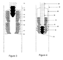
Figure 3 shows apparatus according to an embodiment of the invention prior to deployment of a first cement plug; -
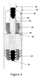
Figure 4 shows the apparatus ofFigure 3 during deployment of a first cement plug; -
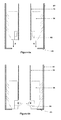
Figure 5 shows the apparatus ofFigure 4 after deployment of the a cement plug and prior to deployment of a second cement plug; -
Figure 6a and 6b show the operation of a deformable section of a cement plug; -
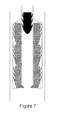
Figure 7 shows an apparatus according to an embodiment of the invention with three cement plugs stored in the basket; -
Figure 8 shows an apparatus according to an embodiment of the invention having a protective sleeve integrated in sections into each cement plug; -
Figure 9 shows the apparatus ofFigure 8 after deployment of a first cement plug; and -
Figure 10 shows a further embodiment of the invention. - With reference to
Figures 3, 4 and5 the apparatus according to an embodiment of the invention comprises abasket 40 located at the end of adrill pipe 30. Aprotective sleeve 38 extends though the inside of thebasket 40 from the end of thedrill pipe 30 to terminate just above the end of the basket. An annulus is created between the inner surface of thebasket 40 and the outer surface of theprotective sleeve 38 defining a receptacle or chamber in which cement plugs 36, 42 are loaded. - The lower end of each
plug formations 44. Theprotective sleeve 38 does not extend down level to the end of thebasket 40 and so allows the resilientlydeformable section 44 of thelowermost cement plug 42 to deform towards the inside of thesleeve 38. This process is shown in greater detail inFigures 6a and 6b . - To deploy the
lowermost plug 42, adart 34 is pumped through thedrill pipe 30 in the usual way. The dart passes through thesleeve 38 and engages with theformations 44 to withdraw thedart 42 from thebasket 40. The presence of thesleeve 38 means that theupper plug 36 is unaffected at this stage. As is shown inFigure 4 , thedart 34 is caught by thedeformable section 44 of thelower cement plug 42 and the pressure applied to it from the surface via thedrill pipe 30 forces the lower cement plug and dart out of thebasket 40 into thewell casing 32. Consequently, there is no specific need to reduce the diameter of the plug over its entire section, and the deformable section may comprise a plurality of fingers, with the minimum being three. - The lower end of the
basket 40 is provided with aplug lock 46, which is forced open by the increased pressure, allowing the cement plug to pass out of thebasket 40, and when the plug has exited (seeFigure 5 ) theplug lock 46 returns back to the closed position to stop the next cement plug 36 from exiting the basket at the same time. The cement is between the lower plug/dart upper dart 35. As the pumping continues, thesecond dart 35 passes through the protective sleeve 38 (seeFigure 5 ) and engage with theupper plug 36 in the same manner as described above. An advantage of this approach is that the second, and indeed all consecutive darts, can be of the same size and proportions as the first dart due to the ability to have identical cement plugs stored in the basket. Thesleeve 38 acts to hold the plugs open so that there is no restriction of the flow diameter by plugs stored in thebasket 40. - As is shown in
Figures 6a and 6b , theupper cement plug 36 moves down thebasket 40 in the direction of arrows A to fill the gap created by the deployment of a previous cement plug. InFigure 6a , theprotective sleeve 38 is supporting the resilientlydeformable section 44. When thecement plug 36 has reached the end of thebasket 40, it is stopped by theplug lock 46. The plug lock can consist of a restriction in the basket section, a spring loaded gate, or any other means that will prevent the plug from exiting the basket due to gravity and/or the friction force created by fluid flow through the cement plug. - When the cement plug has reached the bottom of the
basket 40, as depicted byFigure 6b , the resilientlydeformable section 44 of the cement plug is no longer supported by theprotective sleeve 38 and so deforms towards the inner diameter as shown by arrows B. In this position the deformable section is ready to catch a dart which may be launched down the drill pipe for the purpose of injecting a cement plug into the well casing. - This also allows the removal of limit for the number of cement plugs to be carried in the basket.
Figure 7 , for example, shows the basket carrying three cement plugs. The number of plugs in the basket makes no difference to the ability to pump darts since there is no change to the diameter of the flow passage. Also, the sleeve prevents the dart from engaging any but the lowest plug. - In an alternative embodiment, the protective sleeve is made up of a number of sections, with each section being formed as part of a cement plug. This can be seen in
Figures 8 and 9 . - The
protective sleeve section 52 of thelower cement plug 42 protects the inner diameter of the cement plug from just above thedeformable area 44 and extends up beyond the upper limit of the plug. The section of protective sleeve that extends up beyond the plug can support the deformable section of the cement plug above and ashear section 54 joins the lowerprotective sleeve section 52 with theprotective sleeve section 50 of theupper cement plug 36. - When a
dart 34 is caught in the lower cement plug, theprotective sleeves shear point 54, and thedeformable section 44 of theupper cement plug 36 is no longer supported by theprotective sleeve section 52 and deforms towards the inner diameter. - Advantages of this alternative embodiment are that the cement plugs that are stored in the basket do not need to be pushed down to reach the bottom of the protective sleeve, also there is no need to have a plug lock mechanism at the bottom of the basket to prevent accidental deployment.
- Further changes can be made within the scope of the invention.
Figure 10 shows one embodiment of the invention demonstrating such changes. In this embodiment, no basket is present around the outside of theplugs sleeve 38. Aprotective cap 60 is provided around the top of thesleeve 38 to prevent theplugs drill pipe 30 as the apparatus is run into the well. In all other respects, operation is as described above.
Claims (15)
- An apparatus for installing cement plugs into a well, comprising a protective sleeve having one end adapted to be attached to the end of a drill pipe and arranged to carry a cementing plug around its outer surface such that a dart passing through the drill pipe can pass through the sleeve and engage only on formations on the plug to withdraw it from the end of the sleeve.
- An apparatus as claimed in claim 1, further comprising a tubular basket having one end adapted to be attached to the end of a drill pipe and being open at the other end, the basket defining a receptacle in which a cementing plug can be retained such that a dart passing through the drill pipe can engage on formations on the plug to withdraw it from the basket through the open end; wherein the sleeve extends through the interior of the basket so as to define an annular chamber in which the cement plug can be retained such that the dart can pass through the protective sleeve and only engage the plug by means of the formations at the open end.
- An apparatus as claimed in claim 2, wherein the basket is sized to accommodate more than one cementing plug positioned one above the other, the formations on only the lowermost extending inwards of the sleeve diameter so as to be engageable by a dart.
- An apparatus as claimed in claim 1, 2 or 3, wherein the protective sleeve is arranged to rupture as the lowermost cementing plug is withdrawn so that the formations of the cementing plug immediately above are allowed to project inwardly of the new end of the protective sleeve.
- An apparatus as claimed in any preceding claim, wherein the protective sleeve has substantially the same internal diameter as the drill pipe.
- An apparatus as claimed in any preceding claim, further comprising at least one cementing plug retained around the sleeve such that formations on the plug project radially inwardly of the end of the protective sleeve so as to be engageable by a dart.
- An apparatus as claimed in claim 6, comprising more than one cement plug, each of substantially the same size and dimensions.
- Apparatus as claimed in claim 6 or 7, wherein each cementing plug is formed with a section of the protective sleeve which detaches from the apparatus as the plug is withdrawn.
- An apparatus as claimed in claim 6, 7 or 8, wherein the formations on the cement plug comprise a resiliently deformable section that deforms inwardly when not supported in the sleeve.
- An as claimed in claim 9, wherein the resiliently deformable section comprises at least one finger
- An apparatus as claimed in claim 9 or 10, wherein the resiliently deformable section comprises a shape memory material, or a pivotable member that is biased inwardly by a resilient material.
- A method of deploying a cementing plug, comprising:- loading a cementing plug into an apparatus as claimed in any of claims 1-6;- connecting the apparatus to the end of a drill pipe;- positioning the casing in a well;- pumping a dart from the surface through the drill pipe so as to pass through the protective sleeve and engage the formations on the plug and withdraw it from the sleeve.
- A method as claimed in claim 12, further comprising:- loading more than one cement plugs into the apparatus, one above the other;- pumping a first dart to withdraw the lowermost plug from the sleeve;- allowing the next successive plug to adopt the lowermost position; and- pumping a second dart to withdraw the next plug from the basket.
- A method as claimed in claim 13, wherein the next plug moves to the end of the sleeve to assume the lowermost position.
- A method as claimed in claim 13, wherein withdrawal of a plug from the sleeve serves to also remove a portion of sleeve around which the plug is located.
Priority Applications (6)
| Application Number | Priority Date | Filing Date | Title |
|---|---|---|---|
| EP08170646A EP2194226A1 (en) | 2008-12-04 | 2008-12-04 | Apparatus and Method for Deploying Cementing Plugs |
| US13/130,182 US8887807B2 (en) | 2008-12-04 | 2009-11-24 | Apparatus and methods for deploying cementing plugs |
| PCT/EP2009/008427 WO2010063406A1 (en) | 2008-12-04 | 2009-11-24 | Apparatus and method for deploying cementing plugs |
| BRPI0920993A BRPI0920993A2 (en) | 2008-12-04 | 2009-11-24 | apparatus for installing cement plugs from a well, and method for deploying cementing plugs. |
| GB1108212.0A GB2477068B (en) | 2008-12-04 | 2009-11-24 | Apparatus and method for deploying cementing plugs |
| NO20110756A NO20110756A1 (en) | 2008-12-04 | 2011-05-23 | Apparatus and method for placing cement plugs |
Applications Claiming Priority (1)
| Application Number | Priority Date | Filing Date | Title |
|---|---|---|---|
| EP08170646A EP2194226A1 (en) | 2008-12-04 | 2008-12-04 | Apparatus and Method for Deploying Cementing Plugs |
Publications (1)
| Publication Number | Publication Date |
|---|---|
| EP2194226A1 true EP2194226A1 (en) | 2010-06-09 |
Family
ID=40521897
Family Applications (1)
| Application Number | Title | Priority Date | Filing Date |
|---|---|---|---|
| EP08170646A Withdrawn EP2194226A1 (en) | 2008-12-04 | 2008-12-04 | Apparatus and Method for Deploying Cementing Plugs |
Country Status (6)
| Country | Link |
|---|---|
| US (1) | US8887807B2 (en) |
| EP (1) | EP2194226A1 (en) |
| BR (1) | BRPI0920993A2 (en) |
| GB (1) | GB2477068B (en) |
| NO (1) | NO20110756A1 (en) |
| WO (1) | WO2010063406A1 (en) |
Families Citing this family (6)
| Publication number | Priority date | Publication date | Assignee | Title |
|---|---|---|---|---|
| US8163676B2 (en) | 2007-11-30 | 2012-04-24 | M-I L.L.C. | Emulsifier blend |
| US10107064B2 (en) | 2013-06-06 | 2018-10-23 | Halliburton Energy Services, Inc. | Changeable well seal tool |
| WO2016070071A1 (en) * | 2014-10-31 | 2016-05-06 | Firestone Building Products Co., LLC | Insulation devices including vacuum-insulated capsules |
| WO2019014436A1 (en) * | 2017-07-14 | 2019-01-17 | Conocophillips Company | Delayed fin deployment wiper plug |
| NO20210384A1 (en) | 2018-10-31 | 2021-03-23 | Halliburton Energy Services Inc | Integrated Debris Catcher and Plug System |
| US10844692B1 (en) * | 2019-03-01 | 2020-11-24 | Tim Griffin | Subsurface wellbore wiper deployment system and method of use |
Citations (4)
| Publication number | Priority date | Publication date | Assignee | Title |
|---|---|---|---|---|
| US5787979A (en) * | 1995-04-26 | 1998-08-04 | Weatherford/Lamb, Inc. | Wellbore cementing system |
| WO1999014461A2 (en) * | 1997-09-12 | 1999-03-25 | Weatherford/Lamb, Inc. | A plug for use in wellbore operations, an apparatus for receiving said plug, a plug landing system and a method for cementing tubulars in a wellbore |
| WO1999019601A1 (en) * | 1997-10-11 | 1999-04-22 | Weatherford/Lamb, Inc. | An apparatus and a method for launching plugs |
| US20050103492A1 (en) * | 2003-11-14 | 2005-05-19 | Szarka David D. | Plug systems and methods for using plugs in subterranean formations |
Family Cites Families (1)
| Publication number | Priority date | Publication date | Assignee | Title |
|---|---|---|---|---|
| US7845400B2 (en) * | 2008-01-28 | 2010-12-07 | Baker Hughes Incorporated | Launching tool for releasing cement plugs downhole |
-
2008
- 2008-12-04 EP EP08170646A patent/EP2194226A1/en not_active Withdrawn
-
2009
- 2009-11-24 GB GB1108212.0A patent/GB2477068B/en not_active Expired - Fee Related
- 2009-11-24 US US13/130,182 patent/US8887807B2/en not_active Expired - Fee Related
- 2009-11-24 BR BRPI0920993A patent/BRPI0920993A2/en not_active IP Right Cessation
- 2009-11-24 WO PCT/EP2009/008427 patent/WO2010063406A1/en active Application Filing
-
2011
- 2011-05-23 NO NO20110756A patent/NO20110756A1/en not_active Application Discontinuation
Patent Citations (4)
| Publication number | Priority date | Publication date | Assignee | Title |
|---|---|---|---|---|
| US5787979A (en) * | 1995-04-26 | 1998-08-04 | Weatherford/Lamb, Inc. | Wellbore cementing system |
| WO1999014461A2 (en) * | 1997-09-12 | 1999-03-25 | Weatherford/Lamb, Inc. | A plug for use in wellbore operations, an apparatus for receiving said plug, a plug landing system and a method for cementing tubulars in a wellbore |
| WO1999019601A1 (en) * | 1997-10-11 | 1999-04-22 | Weatherford/Lamb, Inc. | An apparatus and a method for launching plugs |
| US20050103492A1 (en) * | 2003-11-14 | 2005-05-19 | Szarka David D. | Plug systems and methods for using plugs in subterranean formations |
Also Published As
| Publication number | Publication date |
|---|---|
| WO2010063406A1 (en) | 2010-06-10 |
| GB201108212D0 (en) | 2011-06-29 |
| GB2477068B (en) | 2013-04-10 |
| US20130014948A1 (en) | 2013-01-17 |
| US8887807B2 (en) | 2014-11-18 |
| BRPI0920993A2 (en) | 2019-09-24 |
| GB2477068A (en) | 2011-07-20 |
| NO20110756A1 (en) | 2011-06-07 |
Similar Documents
| Publication | Publication Date | Title |
|---|---|---|
| US20200232300A1 (en) | Method for slim hole single trip remedial or plug and abandonment cement barrier | |
| US8887807B2 (en) | Apparatus and methods for deploying cementing plugs | |
| US8127846B2 (en) | Wiper plug perforating system | |
| US9670750B2 (en) | Methods of operating well bore stimulation valves | |
| RU2660704C2 (en) | Barrier testing method | |
| US8327937B2 (en) | Equipment for remote launching of cementing plugs | |
| US20120031614A1 (en) | Apparatus and methods for well cementing | |
| US11047202B2 (en) | Top plug with transitionable seal | |
| EA021471B1 (en) | Fracturing with telescoping members and sealing the annular space | |
| EP3036395B1 (en) | One trip perforating and washing tool for plugging and abandoning wells | |
| US20180112488A1 (en) | Casing floatation system with latch-in-plugs | |
| EP3752704B1 (en) | Curing a lost circulation zone in a wellbore | |
| AU2017276300A1 (en) | System and Method for Detecting Screen-Out Using a Fracturing Valve for Mitigation | |
| US9587456B2 (en) | Packer setting method using disintegrating plug | |
| EP3492693A1 (en) | Downhole inflow production restriction device | |
| US9157295B2 (en) | Control of fluid flow in oil wells | |
| EP3717739B1 (en) | Method and apparatus for washing an upper completion | |
| US10465478B2 (en) | Toe valve | |
| RU2522031C1 (en) | Method of fitting well screen in horizontal steam-injection well | |
| EP3353373B1 (en) | Methods for placing a barrier material in a wellbore to permanently leave tubing in casing for permanent wellbore abandonment | |
| US11920418B2 (en) | Apparatus and method for behind casing washout | |
| US20190292875A1 (en) | Method and System for Plugging A Subterranean Well | |
| NO339623B1 (en) | Arrangement and procedure for the removal of production waste in a well |
Legal Events
| Date | Code | Title | Description |
|---|---|---|---|
| PUAI | Public reference made under article 153(3) epc to a published international application that has entered the european phase |
Free format text: ORIGINAL CODE: 0009012 |
|
| AK | Designated contracting states |
Kind code of ref document: A1 Designated state(s): AT BE BG CH CY CZ DE DK EE ES FI FR GB GR HR HU IE IS IT LI LT LU LV MC MT NL NO PL PT RO SE SI SK TR |
|
| AX | Request for extension of the european patent |
Extension state: AL BA MK RS |
|
| AKY | No designation fees paid | ||
| REG | Reference to a national code |
Ref country code: DE Ref legal event code: 8566 |
|
| STAA | Information on the status of an ep patent application or granted ep patent |
Free format text: STATUS: THE APPLICATION IS DEEMED TO BE WITHDRAWN |
|
| 18D | Application deemed to be withdrawn |
Effective date: 20101210 |