EP2193893A1 - A machine for working cardboard and similar materials - Google Patents
A machine for working cardboard and similar materials Download PDFInfo
- Publication number
- EP2193893A1 EP2193893A1 EP09178017A EP09178017A EP2193893A1 EP 2193893 A1 EP2193893 A1 EP 2193893A1 EP 09178017 A EP09178017 A EP 09178017A EP 09178017 A EP09178017 A EP 09178017A EP 2193893 A1 EP2193893 A1 EP 2193893A1
- Authority
- EP
- European Patent Office
- Prior art keywords
- cardboard
- machine according
- machine
- roller
- brush
- Prior art date
- Legal status (The legal status is an assumption and is not a legal conclusion. Google has not performed a legal analysis and makes no representation as to the accuracy of the status listed.)
- Withdrawn
Links
Images


Classifications
-
- B—PERFORMING OPERATIONS; TRANSPORTING
- B26—HAND CUTTING TOOLS; CUTTING; SEVERING
- B26D—CUTTING; DETAILS COMMON TO MACHINES FOR PERFORATING, PUNCHING, CUTTING-OUT, STAMPING-OUT OR SEVERING
- B26D7/00—Details of apparatus for cutting, cutting-out, stamping-out, punching, perforating, or severing by means other than cutting
- B26D7/20—Cutting beds
-
- B—PERFORMING OPERATIONS; TRANSPORTING
- B26—HAND CUTTING TOOLS; CUTTING; SEVERING
- B26D—CUTTING; DETAILS COMMON TO MACHINES FOR PERFORATING, PUNCHING, CUTTING-OUT, STAMPING-OUT OR SEVERING
- B26D1/00—Cutting through work characterised by the nature or movement of the cutting member or particular materials not otherwise provided for; Apparatus or machines therefor; Cutting members therefor
- B26D1/01—Cutting through work characterised by the nature or movement of the cutting member or particular materials not otherwise provided for; Apparatus or machines therefor; Cutting members therefor involving a cutting member which does not travel with the work
- B26D1/12—Cutting through work characterised by the nature or movement of the cutting member or particular materials not otherwise provided for; Apparatus or machines therefor; Cutting members therefor involving a cutting member which does not travel with the work having a cutting member moving about an axis
- B26D1/14—Cutting through work characterised by the nature or movement of the cutting member or particular materials not otherwise provided for; Apparatus or machines therefor; Cutting members therefor involving a cutting member which does not travel with the work having a cutting member moving about an axis with a circular cutting member, e.g. disc cutter
- B26D1/22—Cutting through work characterised by the nature or movement of the cutting member or particular materials not otherwise provided for; Apparatus or machines therefor; Cutting members therefor involving a cutting member which does not travel with the work having a cutting member moving about an axis with a circular cutting member, e.g. disc cutter coacting with a movable member, e.g. a roller
- B26D1/225—Cutting through work characterised by the nature or movement of the cutting member or particular materials not otherwise provided for; Apparatus or machines therefor; Cutting members therefor involving a cutting member which does not travel with the work having a cutting member moving about an axis with a circular cutting member, e.g. disc cutter coacting with a movable member, e.g. a roller for thin material, e.g. for sheets, strips or the like
-
- B—PERFORMING OPERATIONS; TRANSPORTING
- B26—HAND CUTTING TOOLS; CUTTING; SEVERING
- B26D—CUTTING; DETAILS COMMON TO MACHINES FOR PERFORATING, PUNCHING, CUTTING-OUT, STAMPING-OUT OR SEVERING
- B26D3/00—Cutting work characterised by the nature of the cut made; Apparatus therefor
- B26D3/08—Making a superficial cut in the surface of the work without removal of material, e.g. scoring, incising
Definitions
- This invention is in the technical sector relating to cardboard working.
- this invention relates to a machine for working cardboard and similar materials.
- Working cardboard whether it is in slabs, sheets or strips, corrugated or single-layer, basically involves making cuts, creases and the like.
- the prior art machines are equipped with suitable opposing means located on the opposite side of the cardboard to be worked to the disk-type elements for cutting or punching.
- the opposing means comprise steel rollers positioned opposite the disk-type or roller-type cutting or creasing elements.
- An alternative solution to the rollers uses flat opposing elements, such as plates and the like.
- the plate means generate unwanted friction which opposes rapid cardboard feed
- the roller means in order to overcome said disadvantage must be made to rotate at the same speed of rotation as the cutting elements, with consequent complications due to the complexity of the plant, both as regards their motorisation and for controlling their speed.
- the Applicant created a new solution consisting of a machine for working cardboard in which the opposing means are brushes which form respective flat surfaces on which the pieces of cardboard can slide. Said solution forms the subject-matter of industrial invention patent application number BO2006A000381.
- a first disadvantage is the fact that the bristles forming the brushes, extending longitudinally so that they are perpendicular to the surface for cardboard feed along the machine, may cause the cardboard being fed to jam if the cardboard has sharp cuts which are transversal to the feed direction.
- a second disadvantage linked to use of brush-type means of the known type is the high resistance to cardboard feed caused by the bristles distributed along the feed surface.
- This invention therefore has for an aim to provide a machine for working cardboard and similar materials which is free of the disadvantages described above and which at the same time has a simple structure, is easy to produce and operates effectively.
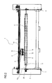
- the numeral 1 denotes as a whole a preferred but non-limiting embodiment of a machine for working cardboard and similar materials.
- the machine 1 comprises a frame 2 consisting of a plurality of uprights and crosspieces, not indicated in detail, and resting on the ground with a plurality of feet 3.
- the machine 1 has a zone 4 for insertion of a piece of cardboard C, visible in Figures 2 and 3 , according to a predetermined direction indicated by the arrow F, towards a series of operating elements designed to make cuts, creases or for other working on the cardboard, the operating elements being described in detail below.
- the machine 1 comprises means 5 for feeding the cardboard comprising two rollers 6, 7 opposite one another, of the substantially known type and not described in detail.
- the machine 1 Downstream of the zone 4 according to the direction of the arrow F, the machine 1 has a first operating unit 8 for cutting and creasing the pieces of cardboard transversally, where the term transversally refers to a direction which is substantially at a right angle to the cardboard C feed direction in the machine 1, the feed direction being indicated by the arrow F in Figure 1 .
- the first operating unit 8 comprises an operating element 9 and a roller 10 for supporting and opposing the cardboard C.
- the operating element 9 advantageously comprises a disk-type cutting device 11, and two creasing devices 12, 13, respectively continuous and intermittent.
- the three devices 11, 12, 13 are mounted on a carriage 14 which can move by sliding, in the substantially known way, on a respective guide 15 extending transversally to the cardboard C feed direction F.
- the devices 11, 12, 13 can be operated independently of each other using respective actuators, advantageously of the pneumatic type, which bring each of them from a respective first, raised non-operating position to a second, lowered operating position in which it engages with the cardboard C.
- the supporting and opposing roller 10 rotates about a respective axis of rotation 10a which is transversal to the feed direction F.
- the machine 1 downstream of the first operating unit 8 according to the direction of the arrow F, the machine 1 has a second operating unit 16 for cutting and creasing the pieces of cardboard C longitudinally, where the term longitudinally refers to a direction which is substantially parallel with the cardboard C feed direction F in the machine 1.
- the second operating unit 16 comprises two operating elements 17, 18 and two respective rollers 19, 20 for supporting and opposing the cardboard C.
- the operating element 17 comprises two disk-type cutting devices 21 each designed to make longitudinal cuts in the cardboard C by operating in conjunction with a respective supporting and opposing roller 19 below.
- the device 21 can be operated using respective actuators 22 between a first, raised non-operating position, visible in Figure 4 , in which the cutting disk 23 does not engage with the cardboard C, and a second, lowered operating position, visible in Figure 5 , in which the cutting disk 23 engages with the cardboard C.
- the supporting and opposing roller 19 rotates about a respective axis of rotation 19a which is transversal to the feed direction F.
- the operating element 18 comprises a creasing device 24 designed to make longitudinal creases in the cardboard C by operating in conjunction with a respective supporting and opposing roller 20 below. Like the devices 11, 12, 13, 21 described above, the creasing device 24 can move between two respective positions, non-operating and operating.
- the supporting and opposing roller 20 also rotates about a respective axis of rotation 20a which is transversal to the feed direction F.
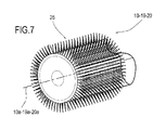
- Each of the supporting and opposing rollers 10, 19, 20, a portion of which is illustrated in Figure 7 is covered by a brush-type surface 25 whose bristles, or thread-like segments, are designed to support the cardboard C and to offer suitable opposition to the operating element 9, 17, 18 during operation of any of its devices 11, 12, 13, 21, 24.
- rollers 10, 19, 20 are opposite respective operating elements 9, 17, 18, which are on the opposite side of the cardboard C.
- the tips of the bristles forming the surface 25 react with both the weight of the cardboard C and the force applied to the cardboard C by the cutting and creasing devices.
- the bristles are gathered in groups distributed in a regular fashion on the outer cylindrical face of the rollers 10, 19, 20.
- the bristles, or thread-like segments are arranged one after another and are fixed on a support 30 which extends longitudinally, the support 30 being wound in a spiral about the roller 10, 19, 20 to form the brush-type surface 25.
- the support 30 is a profile with a U-shaped cross-section.
- the profile forming the support 30 is advantageously a metal profile, in particular made of steel or aluminium.
- the lateral walls of the support 30 are at least partly bent inwards towards each other to form a U shape so as to mechanically hold the bristles or thread-like segments.
- the support 30 accommodates an adhesive material able to secure the bristles or thread-like segments.
- the profile forming the support 30 is wound in a spiral about the roller 10, 19, 20 so that it adheres to the outer surface of the latter and forms the above-mentioned brush-type surface 25.
- the support 30 wound in a spiral is fixed to the roller 10, 19, 20 by suitable fixing means.
- the fixing means comprise welding spots when possible depending on the materials used.
- the support 30 may be fixed to the roller 10, 19, 20 by forcing the former onto the latter.
- the support 30 which can be wound in a spiral about the roller 10, 19, 20, has the advantage of being easy to adapt to any different roller diameter and easily and rapidly substituted in the event of wear or deterioration of the bristles or thread-like segments.
- the bristles are advantageously made of nylon or another synthetic material or even of metal, depending on the material to be supported and on other operating parameters to be selected by the machine user.
- rollers 10, 19, 20 advantageously have motor means, not illustrated, which are designed to make the roller 10, 19, 20 rotate in such a way that it is synchronised with cardboard C feed.
- rotation of the rollers 10, 19, 20 contributes to cardboard C feed in the direction F.
- Figures 2 and 3 show, by way of example, at one longitudinal end of the roller 10, 19, a pulley 26 designed to engage with respective elements, not illustrated, which are designed to pull the roller 10, 19 so that it rotates about its axis 10a, 19a.
- roller 10, 19 is positioned idly on its axis of rotation 10a, 19a.
- the machine according to this invention comprises a belt conveyor, in which the belt is covered by a brush-type surface. Said embodiment, like the roller, allows the cardboard C to be supported during operation of the operating elements.
- the belt conveyor may also be equipped with a motor or may be idle.
- Figure 6 shows an alternative embodiment of the machine 1 described above. For brevity the features of the machine shared by that described above are not described.
- the machine 1 advantageously comprises means 27 for cutting up cardboard C waste pieces obtained after cuts were made in the cardboard by the cutting devices 21. Downstream of the cutting means 27, the machine 1 comprises means 28 for unloading the cut up waste pieces.
- Another advantage linked to the use of the movable supporting and opposing means according to this invention is that of limiting the friction in the cardboard C sliding.
- a further advantage linked to use of the rollers 10, 19, 20 having a brush-type surface 25 is the fact that they are very light and economical compared with conventional solid rubber or steel rollers.
Abstract
A machine for working cardboard and similar materials comprises a supporting frame (2), means (5) for feeding the cardboard in a predetermined feed direction (F), operating elements (9, 17, 18) designed to make cuts, creases and/or for other working on the cardboard, cardboard supporting and opposing rollers (10, 19, 20) which are positioned on the opposite side of the cardboard to the operating elements (9, 17, 18), for opposing the force applied to the cardboard by the operating elements (9, 17, 18).
Description
- This invention is in the technical sector relating to cardboard working.
- In particular, this invention relates to a machine for working cardboard and similar materials.
- Working cardboard, whether it is in slabs, sheets or strips, corrugated or single-layer, basically involves making cuts, creases and the like.
- There are prior art cardboard working machines which are equipped with disk-type, blade-type or even punch elements for making cuts, creases, intermittent pre-breaking line cuts, both longitudinal and transversal.
- In order to carry out said working effectively, the prior art machines are equipped with suitable opposing means located on the opposite side of the cardboard to be worked to the disk-type elements for cutting or punching.
- These opposing means carry out the necessary function of preventing the cardboard from deforming or bending excessively when it is subjected to the forces with components which are perpendicular to it applied by the cutting elements.
- In the prior art solutions the opposing means comprise steel rollers positioned opposite the disk-type or roller-type cutting or creasing elements. An alternative solution to the rollers uses flat opposing elements, such as plates and the like.
- Both types of opposing means mentioned above, although effective are not without disadvantages.
- Whilst on one hand the plate means generate unwanted friction which opposes rapid cardboard feed, the roller means, in order to overcome said disadvantage must be made to rotate at the same speed of rotation as the cutting elements, with consequent complications due to the complexity of the plant, both as regards their motorisation and for controlling their speed.
- To overcome the disadvantages of the prior art, the Applicant created a new solution consisting of a machine for working cardboard in which the opposing means are brushes which form respective flat surfaces on which the pieces of cardboard can slide. Said solution forms the subject-matter of industrial invention patent application number BO2006A000381.
- Even that solution, although solving most of the problems associated with the use of pre-existing means, is not without disadvantages.
- In particular, a first disadvantage is the fact that the bristles forming the brushes, extending longitudinally so that they are perpendicular to the surface for cardboard feed along the machine, may cause the cardboard being fed to jam if the cardboard has sharp cuts which are transversal to the feed direction.
- A second disadvantage linked to use of brush-type means of the known type is the high resistance to cardboard feed caused by the bristles distributed along the feed surface.
- This invention therefore has for an aim to provide a machine for working cardboard and similar materials which is free of the disadvantages described above and which at the same time has a simple structure, is easy to produce and operates effectively.
- The technical features of the invention according to the aforementioned aim may be easily inferred from the content of the appended claims, especially claim 1, and preferably any of the claims that depend, either directly or indirectly, on
claim 1. - The advantages of the invention are more apparent from the detailed description which follows, with reference to the accompanying drawings which illustrate a preferred embodiment of the invention provided merely by way of example without restricting the scope of the inventive concept, and in which:
-
Figure 1 is a schematic side elevation view of a first embodiment of the machine according to this invention; -
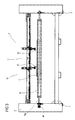
Figure 2 is a cross-section according to the line II - II ofFigure 1 , with some parts cut away for clarity; -
Figure 3 is a cross-section according to the line III - III ofFigure 1 , with some parts cut away for clarity; -
Figures 4 and5 show, in respective side elevation views, an apparatus belonging to the machine in the previous figures, in two different operating steps; -
Figure 6 is a schematic side elevation view of a second embodiment of the machine according to this invention; -
Figure 7 is a schematic perspective top view of a detail of the machines in the previous figures; -
Figure 8 is a schematic perspective top view of a preferred embodiment of the detail ofFigure 7 ; -
Figure 9 is an exploded schematic view of the detail ofFigure 8 . - With reference to the accompanying drawings from 1 to 5, the
numeral 1 denotes as a whole a preferred but non-limiting embodiment of a machine for working cardboard and similar materials. - As shown in
Figure 1 , themachine 1 comprises aframe 2 consisting of a plurality of uprights and crosspieces, not indicated in detail, and resting on the ground with a plurality offeet 3. - The
machine 1 has azone 4 for insertion of a piece of cardboard C, visible inFigures 2 and3 , according to a predetermined direction indicated by the arrow F, towards a series of operating elements designed to make cuts, creases or for other working on the cardboard, the operating elements being described in detail below. - Again with reference to
Figure 1 , close to theinsertion zone 4, themachine 1 comprises means 5 for feeding the cardboard comprising tworollers - Downstream of the
zone 4 according to the direction of the arrow F, themachine 1 has afirst operating unit 8 for cutting and creasing the pieces of cardboard transversally, where the term transversally refers to a direction which is substantially at a right angle to the cardboard C feed direction in themachine 1, the feed direction being indicated by the arrow F inFigure 1 . - As
Figure 2 also shows, thefirst operating unit 8 comprises anoperating element 9 and aroller 10 for supporting and opposing the cardboard C. - The
operating element 9 advantageously comprises a disk-type cutting device 11, and twocreasing devices - The three
devices carriage 14 which can move by sliding, in the substantially known way, on arespective guide 15 extending transversally to the cardboard C feed direction F. - The
devices - The supporting and
opposing roller 10 rotates about a respective axis ofrotation 10a which is transversal to the feed direction F. - Also with reference to
Figure 1 , downstream of thefirst operating unit 8 according to the direction of the arrow F, themachine 1 has asecond operating unit 16 for cutting and creasing the pieces of cardboard C longitudinally, where the term longitudinally refers to a direction which is substantially parallel with the cardboard C feed direction F in themachine 1. - The
second operating unit 16 comprises twooperating elements respective rollers - As is also illustrated in
Figure 3 , theoperating element 17 comprises two disk-type cutting devices 21 each designed to make longitudinal cuts in the cardboard C by operating in conjunction with a respective supporting andopposing roller 19 below. As shown inFigures 4 and5 , thedevice 21 can be operated usingrespective actuators 22 between a first, raised non-operating position, visible inFigure 4 , in which thecutting disk 23 does not engage with the cardboard C, and a second, lowered operating position, visible inFigure 5 , in which thecutting disk 23 engages with the cardboard C. - The supporting and
opposing roller 19 rotates about a respective axis ofrotation 19a which is transversal to the feed direction F. - The
operating element 18 comprises acreasing device 24 designed to make longitudinal creases in the cardboard C by operating in conjunction with a respective supporting andopposing roller 20 below. Like thedevices creasing device 24 can move between two respective positions, non-operating and operating. - The supporting and
opposing roller 20 also rotates about a respective axis ofrotation 20a which is transversal to the feed direction F. - Each of the supporting and
opposing rollers Figure 7 , is covered by a brush-type surface 25 whose bristles, or thread-like segments, are designed to support the cardboard C and to offer suitable opposition to theoperating element devices - As illustrated in
Figures 2 to 5 , therollers respective operating elements - In their action supporting the cardboard C and opposing the
operating elements surface 25 react with both the weight of the cardboard C and the force applied to the cardboard C by the cutting and creasing devices. - Preferably, in forming the brush-
type surface 25, the bristles are gathered in groups distributed in a regular fashion on the outer cylindrical face of therollers - Advantageously, according to the preferred non-limiting embodiment illustrated in
Figures 8 and 9 , the bristles, or thread-like segments, are arranged one after another and are fixed on asupport 30 which extends longitudinally, thesupport 30 being wound in a spiral about theroller type surface 25. - As
Figures 8 and 9 show, thesupport 30 is a profile with a U-shaped cross-section. - The profile forming the
support 30 is advantageously a metal profile, in particular made of steel or aluminium. - Advantageously, the lateral walls of the
support 30 are at least partly bent inwards towards each other to form a U shape so as to mechanically hold the bristles or thread-like segments. - Advantageously, thanks to its concave U shape, the
support 30 accommodates an adhesive material able to secure the bristles or thread-like segments. - As already indicated, during production the profile forming the
support 30 is wound in a spiral about theroller type surface 25. - Advantageously, the
support 30 wound in a spiral is fixed to theroller - In particular, the fixing means, not illustrated, comprise welding spots when possible depending on the materials used. Alternatively, the
support 30 may be fixed to theroller - The
support 30 which can be wound in a spiral about theroller - The bristles are advantageously made of nylon or another synthetic material or even of metal, depending on the material to be supported and on other operating parameters to be selected by the machine user.
- In the embodiment of the
machine 1 illustrated inFigures 1 to 5 , the supporting andopposing rollers operating units type surface 25, although said representation does not limit the scope of the invention in any way. - In other words, without departing from the protective scope of this invention, there are machines which are also equipped with only one roller covered with the brush-
type surface 25, whilst the other rollers are of conventional types such as solid rubber rollers or steel rollers. - The
rollers roller - Advantageously, rotation of the
rollers -
Figures 2 and3 show, by way of example, at one longitudinal end of theroller pulley 26 designed to engage with respective elements, not illustrated, which are designed to pull theroller axis - Alternatively, the
roller rotation - According to an alternative embodiment, not illustrated, the machine according to this invention comprises a belt conveyor, in which the belt is covered by a brush-type surface. Said embodiment, like the roller, allows the cardboard C to be supported during operation of the operating elements.
- The belt conveyor may also be equipped with a motor or may be idle.
- The
rollers type surfaces 25, form, for themachine 1, respective movable elements for supporting and opposing the cardboard C. -
Figure 6 shows an alternative embodiment of themachine 1 described above. For brevity the features of the machine shared by that described above are not described. - According to the embodiment illustrated in
Figure 6 , themachine 1 according to this invention advantageously comprises means 27 for cutting up cardboard C waste pieces obtained after cuts were made in the cardboard by the cuttingdevices 21. Downstream of the cutting means 27, themachine 1 comprises means 28 for unloading the cut up waste pieces. - In practice, the use of cardboard C supporting and opposing means according to this invention advantageously makes it possible to prevent the cardboard C from jamming as it is fed along inside the
machine 1. - Another advantage linked to the use of the movable supporting and opposing means according to this invention is that of limiting the friction in the cardboard C sliding.
- A further advantage linked to use of the
rollers type surface 25 is the fact that they are very light and economical compared with conventional solid rubber or steel rollers. - The invention described above is susceptible of industrial application and may be modified and adapted in several ways without thereby departing from the scope of the inventive concept. Moreover, all details of the invention may be substituted by technically equivalent elements.
Claims (11)
- A machine for working cardboard (C) and similar materials, comprising- a supporting frame (2),- means (5) for feeding the cardboard (C) in a predetermined feed direction (F),- operating elements (9, 17, 18) designed to make cuts, creases and/or for other working on the cardboard (C),- cardboard (C) supporting and opposing means, positioned on the opposite side of the cardboard (C) to the operating elements (9, 17, 18) so as to oppose the force applied to the cardboard (C) by the operating elements (9, 17, 18), the machine being characterised in that the supporting and opposing means comprise at least one movable element which is at least partly covered by a brush-type surface (25) and designed to support the cardboard (C) during operation of the operating elements (9, 17, 18).
- The machine according to claim 1, characterised in that the movable element comprises a roller (10, 19, 20) able to rotate about a respective axis of rotation (10a, 19a, 20a) which is transversal relative to the cardboard (C) predetermined longitudinal direction of feed (F), the brush-type surface (25) at least partly covering the roller (10, 19, 20).
- The machine according to claim 1, characterised in that the movable element comprises a belt conveyor, the brush-type surface (25) at least partly covering the belt of the conveyor.
- The machine according to any of the claims from 1 to 3, characterised in that the brush-type surface (25) consists of a plurality of thread-like segments.
- The machine according to claim 4, characterised in that the thread-like segments are gathered in groups.
- The machine according to claim 4 or 5,
characterised in that the thread-like segments are arranged one after another and are fixed on a support (30) which extends longitudinally, said longitudinal support being wound in a spiral about the roller (10, 19, 20). - The machine according to claim 6, characterised in that the longitudinal support (30) is made of metal material.
- The machine according to claim 6 or 7, characterised in that the support (30) has a U-shaped cross-section.
- The machine according to any of the claims from 1 to 8, characterised in that it comprises motor means designed to move the movable element in such a way that it is synchronised with cardboard (C) feed.
- The machine according to any of the claims from 1 to 9, characterised in that it comprises means (27) for cutting up cardboard (C) waste pieces obtained after cuts were made in the cardboard.
- The machine according to claim 10, characterised in that it comprises means (28) for unloading the cut up waste pieces.
Applications Claiming Priority (1)
| Application Number | Priority Date | Filing Date | Title |
|---|---|---|---|
| IT000733A ITBO20080733A1 (en) | 2008-12-04 | 2008-12-04 | MACHINE FOR CARTON AND SIMILAR MATERIALS |
Publications (1)
| Publication Number | Publication Date |
|---|---|
| EP2193893A1 true EP2193893A1 (en) | 2010-06-09 |
Family
ID=41259689
Family Applications (1)
| Application Number | Title | Priority Date | Filing Date |
|---|---|---|---|
| EP09178017A Withdrawn EP2193893A1 (en) | 2008-12-04 | 2009-12-04 | A machine for working cardboard and similar materials |
Country Status (2)
| Country | Link |
|---|---|
| EP (1) | EP2193893A1 (en) |
| IT (1) | ITBO20080733A1 (en) |
Cited By (4)
| Publication number | Priority date | Publication date | Assignee | Title |
|---|---|---|---|---|
| DE202015006139U1 (en) | 2015-08-31 | 2015-10-15 | G. Kraft Maschinenbau Gmbh | Device for scoring, perforating, cutting and scoring flat objects |
| WO2016203424A1 (en) * | 2015-06-17 | 2016-12-22 | Panotec S.R.L. | Pneumatic drive unit for a work tool of a relatively rigid material and corresponding machine for working a relatively rigid material |
| DE102015011399A1 (en) | 2015-08-31 | 2017-03-02 | G. Kraft Maschinenbau Gmbh | Device and method for grooving, perforating, cutting and scoring of flat elements |
| JP2021028103A (en) * | 2019-08-09 | 2021-02-25 | 株式会社リコー | Sheet processing device and image formation system |
Citations (7)
| Publication number | Priority date | Publication date | Assignee | Title |
|---|---|---|---|---|
| US3599518A (en) * | 1968-02-16 | 1971-08-17 | Harris Intertype Corp | Paperboard cutting apparatus and method |
| US4003276A (en) * | 1974-09-30 | 1977-01-18 | Molins Machine Company, Inc. | Slitter and dust collector therefor |
| GB2153791A (en) * | 1984-01-26 | 1985-08-29 | Gerber Garment Technology Inc | Unloading sheets from a conveyor |
| EP0443396A2 (en) * | 1990-02-21 | 1991-08-28 | PETERS MASCHINENFABRIK GmbH | Apparatus to cut longitudinally a moving strip of material |
| JP2003275026A (en) * | 2002-03-25 | 2003-09-30 | Yuichiro Niizaki | Waved channel brush material and method for manufacturing the same |
| WO2005118238A1 (en) * | 2004-05-26 | 2005-12-15 | Bhs Corrugated Maschinen Und Anlagenbau Gmbh | Brush cylinder |
| EP1857235A2 (en) * | 2006-05-17 | 2007-11-21 | L.C.R. Macchine Automatiche S.R.L. | Machine for working cardboard and similar |
-
2008
- 2008-12-04 IT IT000733A patent/ITBO20080733A1/en unknown
-
2009
- 2009-12-04 EP EP09178017A patent/EP2193893A1/en not_active Withdrawn
Patent Citations (7)
| Publication number | Priority date | Publication date | Assignee | Title |
|---|---|---|---|---|
| US3599518A (en) * | 1968-02-16 | 1971-08-17 | Harris Intertype Corp | Paperboard cutting apparatus and method |
| US4003276A (en) * | 1974-09-30 | 1977-01-18 | Molins Machine Company, Inc. | Slitter and dust collector therefor |
| GB2153791A (en) * | 1984-01-26 | 1985-08-29 | Gerber Garment Technology Inc | Unloading sheets from a conveyor |
| EP0443396A2 (en) * | 1990-02-21 | 1991-08-28 | PETERS MASCHINENFABRIK GmbH | Apparatus to cut longitudinally a moving strip of material |
| JP2003275026A (en) * | 2002-03-25 | 2003-09-30 | Yuichiro Niizaki | Waved channel brush material and method for manufacturing the same |
| WO2005118238A1 (en) * | 2004-05-26 | 2005-12-15 | Bhs Corrugated Maschinen Und Anlagenbau Gmbh | Brush cylinder |
| EP1857235A2 (en) * | 2006-05-17 | 2007-11-21 | L.C.R. Macchine Automatiche S.R.L. | Machine for working cardboard and similar |
Cited By (7)
| Publication number | Priority date | Publication date | Assignee | Title |
|---|---|---|---|---|
| WO2016203424A1 (en) * | 2015-06-17 | 2016-12-22 | Panotec S.R.L. | Pneumatic drive unit for a work tool of a relatively rigid material and corresponding machine for working a relatively rigid material |
| CN108136710A (en) * | 2015-06-17 | 2018-06-08 | 国际箱包有限责任公司 | For the pneumatic drive unit of machining tool made of relatively rigid material and the corresponding machine for processing relatively rigid material |
| JP2018527196A (en) * | 2015-06-17 | 2018-09-20 | インターナショナル ボックスィズ エス.アール.エル. | Pneumatic drive unit for relatively rigid material processing tools and corresponding machines for processing relatively rigid material |
| DE202015006139U1 (en) | 2015-08-31 | 2015-10-15 | G. Kraft Maschinenbau Gmbh | Device for scoring, perforating, cutting and scoring flat objects |
| DE102015011399A1 (en) | 2015-08-31 | 2017-03-02 | G. Kraft Maschinenbau Gmbh | Device and method for grooving, perforating, cutting and scoring of flat elements |
| DE102015011399B4 (en) | 2015-08-31 | 2020-01-23 | G. Kraft Maschinenbau Gmbh | Device and method for scoring, perforating, cutting and scoring flat elements |
| JP2021028103A (en) * | 2019-08-09 | 2021-02-25 | 株式会社リコー | Sheet processing device and image formation system |
Also Published As
| Publication number | Publication date |
|---|---|
| ITBO20080733A1 (en) | 2010-06-05 |
Similar Documents
| Publication | Publication Date | Title |
|---|---|---|
| US6607082B2 (en) | Device for removal of trimmings in the production of rolls of web material | |
| EP2193893A1 (en) | A machine for working cardboard and similar materials | |
| CN106488988B (en) | Leather stamping machine | |
| WO2004060645B1 (en) | Method apparatus and system for making cushioning product, and roll tensioner therefor | |
| EP2226170B1 (en) | Supply chain frame for automatic slicing machines | |
| US4364423A (en) | Rotating disc splitter | |
| EP0115208B1 (en) | Card feeder control | |
| US2747664A (en) | Pressure-sensitive tape dispensing machine | |
| JP5134093B2 (en) | Cutting soft food chunks | |
| EP3056458B1 (en) | Rewinding machine | |
| CA2402691C (en) | Cutting system for cutting profiles in air-permeable and resilient materials and method | |
| US3890868A (en) | Insulation cutter | |
| US20170239907A1 (en) | Machine for the production of cardboard tubes | |
| DE69919530T2 (en) | DEVICE FOR ASSEMBLING OBJECTS | |
| EP1120209A2 (en) | Automatic machine for slitting and creasing paperboard sheets and the like | |
| CN115835942A (en) | Apparatus and method for cutting woven sheet fabric | |
| KR101121081B1 (en) | Width directional forming equipment and forming device | |
| EP2979831B1 (en) | Progressive slitting apparatus | |
| US2022799A (en) | Cutting machinery | |
| US20060199719A1 (en) | Roll stand paper guide | |
| CN211387111U (en) | Steel plate splitting machine | |
| KR20150003386A (en) | Machine for processing elements in sheet form, including a feed board fitted with conveying means | |
| US633321A (en) | Cloth-cutter. | |
| EP2390211B1 (en) | An apparatus for unwinding and slitting a material web | |
| US1878453A (en) | Rubber cutting machine |
Legal Events
| Date | Code | Title | Description |
|---|---|---|---|
| PUAI | Public reference made under article 153(3) epc to a published international application that has entered the european phase |
Free format text: ORIGINAL CODE: 0009012 |
|
| AK | Designated contracting states |
Kind code of ref document: A1 Designated state(s): AT BE BG CH CY CZ DE DK EE ES FI FR GB GR HR HU IE IS IT LI LT LU LV MC MK MT NL NO PL PT RO SE SI SK SM TR |
|
| AX | Request for extension of the european patent |
Extension state: AL BA RS |
|
| STAA | Information on the status of an ep patent application or granted ep patent |
Free format text: STATUS: THE APPLICATION IS DEEMED TO BE WITHDRAWN |
|
| 18D | Application deemed to be withdrawn |
Effective date: 20101210 |