EP2193764A1 - Metal-on-metal modular hybrid liner - Google Patents
Metal-on-metal modular hybrid liner Download PDFInfo
- Publication number
- EP2193764A1 EP2193764A1 EP09178414A EP09178414A EP2193764A1 EP 2193764 A1 EP2193764 A1 EP 2193764A1 EP 09178414 A EP09178414 A EP 09178414A EP 09178414 A EP09178414 A EP 09178414A EP 2193764 A1 EP2193764 A1 EP 2193764A1
- Authority
- EP
- European Patent Office
- Prior art keywords
- shell
- bearing member
- compressible
- joint assembly
- prosthetic joint
- Prior art date
- Legal status (The legal status is an assumption and is not a legal conclusion. Google has not performed a legal analysis and makes no representation as to the accuracy of the status listed.)
- Granted
Links
Images


Classifications
-
- A—HUMAN NECESSITIES
- A61—MEDICAL OR VETERINARY SCIENCE; HYGIENE
- A61F—FILTERS IMPLANTABLE INTO BLOOD VESSELS; PROSTHESES; DEVICES PROVIDING PATENCY TO, OR PREVENTING COLLAPSING OF, TUBULAR STRUCTURES OF THE BODY, e.g. STENTS; ORTHOPAEDIC, NURSING OR CONTRACEPTIVE DEVICES; FOMENTATION; TREATMENT OR PROTECTION OF EYES OR EARS; BANDAGES, DRESSINGS OR ABSORBENT PADS; FIRST-AID KITS
- A61F2/00—Filters implantable into blood vessels; Prostheses, i.e. artificial substitutes or replacements for parts of the body; Appliances for connecting them with the body; Devices providing patency to, or preventing collapsing of, tubular structures of the body, e.g. stents
- A61F2/02—Prostheses implantable into the body
- A61F2/30—Joints
- A61F2/32—Joints for the hip
- A61F2/34—Acetabular cups
-
- A—HUMAN NECESSITIES
- A61—MEDICAL OR VETERINARY SCIENCE; HYGIENE
- A61F—FILTERS IMPLANTABLE INTO BLOOD VESSELS; PROSTHESES; DEVICES PROVIDING PATENCY TO, OR PREVENTING COLLAPSING OF, TUBULAR STRUCTURES OF THE BODY, e.g. STENTS; ORTHOPAEDIC, NURSING OR CONTRACEPTIVE DEVICES; FOMENTATION; TREATMENT OR PROTECTION OF EYES OR EARS; BANDAGES, DRESSINGS OR ABSORBENT PADS; FIRST-AID KITS
- A61F2/00—Filters implantable into blood vessels; Prostheses, i.e. artificial substitutes or replacements for parts of the body; Appliances for connecting them with the body; Devices providing patency to, or preventing collapsing of, tubular structures of the body, e.g. stents
- A61F2/02—Prostheses implantable into the body
- A61F2/30—Joints
- A61F2/30721—Accessories
- A61F2/30734—Modular inserts, sleeves or augments, e.g. placed on proximal part of stem for fixation purposes or wedges for bridging a bone defect
-
- A—HUMAN NECESSITIES
- A61—MEDICAL OR VETERINARY SCIENCE; HYGIENE
- A61F—FILTERS IMPLANTABLE INTO BLOOD VESSELS; PROSTHESES; DEVICES PROVIDING PATENCY TO, OR PREVENTING COLLAPSING OF, TUBULAR STRUCTURES OF THE BODY, e.g. STENTS; ORTHOPAEDIC, NURSING OR CONTRACEPTIVE DEVICES; FOMENTATION; TREATMENT OR PROTECTION OF EYES OR EARS; BANDAGES, DRESSINGS OR ABSORBENT PADS; FIRST-AID KITS
- A61F2/00—Filters implantable into blood vessels; Prostheses, i.e. artificial substitutes or replacements for parts of the body; Appliances for connecting them with the body; Devices providing patency to, or preventing collapsing of, tubular structures of the body, e.g. stents
- A61F2/02—Prostheses implantable into the body
- A61F2/30—Joints
- A61F2002/30001—Additional features of subject-matter classified in A61F2/28, A61F2/30 and subgroups thereof
- A61F2002/30003—Material related properties of the prosthesis or of a coating on the prosthesis
- A61F2002/30004—Material related properties of the prosthesis or of a coating on the prosthesis the prosthesis being made from materials having different values of a given property at different locations within the same prosthesis
- A61F2002/30014—Material related properties of the prosthesis or of a coating on the prosthesis the prosthesis being made from materials having different values of a given property at different locations within the same prosthesis differing in elasticity, stiffness or compressibility
-
- A—HUMAN NECESSITIES
- A61—MEDICAL OR VETERINARY SCIENCE; HYGIENE
- A61F—FILTERS IMPLANTABLE INTO BLOOD VESSELS; PROSTHESES; DEVICES PROVIDING PATENCY TO, OR PREVENTING COLLAPSING OF, TUBULAR STRUCTURES OF THE BODY, e.g. STENTS; ORTHOPAEDIC, NURSING OR CONTRACEPTIVE DEVICES; FOMENTATION; TREATMENT OR PROTECTION OF EYES OR EARS; BANDAGES, DRESSINGS OR ABSORBENT PADS; FIRST-AID KITS
- A61F2/00—Filters implantable into blood vessels; Prostheses, i.e. artificial substitutes or replacements for parts of the body; Appliances for connecting them with the body; Devices providing patency to, or preventing collapsing of, tubular structures of the body, e.g. stents
- A61F2/02—Prostheses implantable into the body
- A61F2/30—Joints
- A61F2002/30001—Additional features of subject-matter classified in A61F2/28, A61F2/30 and subgroups thereof
- A61F2002/30108—Shapes
- A61F2002/3011—Cross-sections or two-dimensional shapes
- A61F2002/30112—Rounded shapes, e.g. with rounded corners
-
- A—HUMAN NECESSITIES
- A61—MEDICAL OR VETERINARY SCIENCE; HYGIENE
- A61F—FILTERS IMPLANTABLE INTO BLOOD VESSELS; PROSTHESES; DEVICES PROVIDING PATENCY TO, OR PREVENTING COLLAPSING OF, TUBULAR STRUCTURES OF THE BODY, e.g. STENTS; ORTHOPAEDIC, NURSING OR CONTRACEPTIVE DEVICES; FOMENTATION; TREATMENT OR PROTECTION OF EYES OR EARS; BANDAGES, DRESSINGS OR ABSORBENT PADS; FIRST-AID KITS
- A61F2/00—Filters implantable into blood vessels; Prostheses, i.e. artificial substitutes or replacements for parts of the body; Appliances for connecting them with the body; Devices providing patency to, or preventing collapsing of, tubular structures of the body, e.g. stents
- A61F2/02—Prostheses implantable into the body
- A61F2/30—Joints
- A61F2002/30001—Additional features of subject-matter classified in A61F2/28, A61F2/30 and subgroups thereof
- A61F2002/30316—The prosthesis having different structural features at different locations within the same prosthesis; Connections between prosthetic parts; Special structural features of bone or joint prostheses not otherwise provided for
- A61F2002/30329—Connections or couplings between prosthetic parts, e.g. between modular parts; Connecting elements
- A61F2002/30331—Connections or couplings between prosthetic parts, e.g. between modular parts; Connecting elements made by longitudinally pushing a protrusion into a complementarily-shaped recess, e.g. held by friction fit
- A61F2002/30362—Connections or couplings between prosthetic parts, e.g. between modular parts; Connecting elements made by longitudinally pushing a protrusion into a complementarily-shaped recess, e.g. held by friction fit with possibility of relative movement between the protrusion and the recess
- A61F2002/30364—Rotation about the common longitudinal axis
- A61F2002/30367—Rotation about the common longitudinal axis with additional means for preventing said rotation
-
- A—HUMAN NECESSITIES
- A61—MEDICAL OR VETERINARY SCIENCE; HYGIENE
- A61F—FILTERS IMPLANTABLE INTO BLOOD VESSELS; PROSTHESES; DEVICES PROVIDING PATENCY TO, OR PREVENTING COLLAPSING OF, TUBULAR STRUCTURES OF THE BODY, e.g. STENTS; ORTHOPAEDIC, NURSING OR CONTRACEPTIVE DEVICES; FOMENTATION; TREATMENT OR PROTECTION OF EYES OR EARS; BANDAGES, DRESSINGS OR ABSORBENT PADS; FIRST-AID KITS
- A61F2/00—Filters implantable into blood vessels; Prostheses, i.e. artificial substitutes or replacements for parts of the body; Appliances for connecting them with the body; Devices providing patency to, or preventing collapsing of, tubular structures of the body, e.g. stents
- A61F2/02—Prostheses implantable into the body
- A61F2/30—Joints
- A61F2002/30001—Additional features of subject-matter classified in A61F2/28, A61F2/30 and subgroups thereof
- A61F2002/30316—The prosthesis having different structural features at different locations within the same prosthesis; Connections between prosthetic parts; Special structural features of bone or joint prostheses not otherwise provided for
- A61F2002/30329—Connections or couplings between prosthetic parts, e.g. between modular parts; Connecting elements
- A61F2002/30331—Connections or couplings between prosthetic parts, e.g. between modular parts; Connecting elements made by longitudinally pushing a protrusion into a complementarily-shaped recess, e.g. held by friction fit
- A61F2002/30378—Spherically-shaped protrusion and recess
-
- A—HUMAN NECESSITIES
- A61—MEDICAL OR VETERINARY SCIENCE; HYGIENE
- A61F—FILTERS IMPLANTABLE INTO BLOOD VESSELS; PROSTHESES; DEVICES PROVIDING PATENCY TO, OR PREVENTING COLLAPSING OF, TUBULAR STRUCTURES OF THE BODY, e.g. STENTS; ORTHOPAEDIC, NURSING OR CONTRACEPTIVE DEVICES; FOMENTATION; TREATMENT OR PROTECTION OF EYES OR EARS; BANDAGES, DRESSINGS OR ABSORBENT PADS; FIRST-AID KITS
- A61F2/00—Filters implantable into blood vessels; Prostheses, i.e. artificial substitutes or replacements for parts of the body; Appliances for connecting them with the body; Devices providing patency to, or preventing collapsing of, tubular structures of the body, e.g. stents
- A61F2/02—Prostheses implantable into the body
- A61F2/30—Joints
- A61F2002/30001—Additional features of subject-matter classified in A61F2/28, A61F2/30 and subgroups thereof
- A61F2002/30316—The prosthesis having different structural features at different locations within the same prosthesis; Connections between prosthetic parts; Special structural features of bone or joint prostheses not otherwise provided for
- A61F2002/30329—Connections or couplings between prosthetic parts, e.g. between modular parts; Connecting elements
- A61F2002/30448—Connections or couplings between prosthetic parts, e.g. between modular parts; Connecting elements using adhesives
-
- A—HUMAN NECESSITIES
- A61—MEDICAL OR VETERINARY SCIENCE; HYGIENE
- A61F—FILTERS IMPLANTABLE INTO BLOOD VESSELS; PROSTHESES; DEVICES PROVIDING PATENCY TO, OR PREVENTING COLLAPSING OF, TUBULAR STRUCTURES OF THE BODY, e.g. STENTS; ORTHOPAEDIC, NURSING OR CONTRACEPTIVE DEVICES; FOMENTATION; TREATMENT OR PROTECTION OF EYES OR EARS; BANDAGES, DRESSINGS OR ABSORBENT PADS; FIRST-AID KITS
- A61F2/00—Filters implantable into blood vessels; Prostheses, i.e. artificial substitutes or replacements for parts of the body; Appliances for connecting them with the body; Devices providing patency to, or preventing collapsing of, tubular structures of the body, e.g. stents
- A61F2/02—Prostheses implantable into the body
- A61F2/30—Joints
- A61F2002/30001—Additional features of subject-matter classified in A61F2/28, A61F2/30 and subgroups thereof
- A61F2002/30316—The prosthesis having different structural features at different locations within the same prosthesis; Connections between prosthetic parts; Special structural features of bone or joint prostheses not otherwise provided for
- A61F2002/30329—Connections or couplings between prosthetic parts, e.g. between modular parts; Connecting elements
- A61F2002/30474—Connections or couplings between prosthetic parts, e.g. between modular parts; Connecting elements using an intermediate sleeve interposed between both prosthetic parts to be coupled
-
- A—HUMAN NECESSITIES
- A61—MEDICAL OR VETERINARY SCIENCE; HYGIENE
- A61F—FILTERS IMPLANTABLE INTO BLOOD VESSELS; PROSTHESES; DEVICES PROVIDING PATENCY TO, OR PREVENTING COLLAPSING OF, TUBULAR STRUCTURES OF THE BODY, e.g. STENTS; ORTHOPAEDIC, NURSING OR CONTRACEPTIVE DEVICES; FOMENTATION; TREATMENT OR PROTECTION OF EYES OR EARS; BANDAGES, DRESSINGS OR ABSORBENT PADS; FIRST-AID KITS
- A61F2/00—Filters implantable into blood vessels; Prostheses, i.e. artificial substitutes or replacements for parts of the body; Appliances for connecting them with the body; Devices providing patency to, or preventing collapsing of, tubular structures of the body, e.g. stents
- A61F2/02—Prostheses implantable into the body
- A61F2/30—Joints
- A61F2002/30001—Additional features of subject-matter classified in A61F2/28, A61F2/30 and subgroups thereof
- A61F2002/30316—The prosthesis having different structural features at different locations within the same prosthesis; Connections between prosthetic parts; Special structural features of bone or joint prostheses not otherwise provided for
- A61F2002/30329—Connections or couplings between prosthetic parts, e.g. between modular parts; Connecting elements
- A61F2002/30476—Connections or couplings between prosthetic parts, e.g. between modular parts; Connecting elements locked by an additional locking mechanism
- A61F2002/30495—Connections or couplings between prosthetic parts, e.g. between modular parts; Connecting elements locked by an additional locking mechanism using a locking ring
-
- A—HUMAN NECESSITIES
- A61—MEDICAL OR VETERINARY SCIENCE; HYGIENE
- A61F—FILTERS IMPLANTABLE INTO BLOOD VESSELS; PROSTHESES; DEVICES PROVIDING PATENCY TO, OR PREVENTING COLLAPSING OF, TUBULAR STRUCTURES OF THE BODY, e.g. STENTS; ORTHOPAEDIC, NURSING OR CONTRACEPTIVE DEVICES; FOMENTATION; TREATMENT OR PROTECTION OF EYES OR EARS; BANDAGES, DRESSINGS OR ABSORBENT PADS; FIRST-AID KITS
- A61F2/00—Filters implantable into blood vessels; Prostheses, i.e. artificial substitutes or replacements for parts of the body; Appliances for connecting them with the body; Devices providing patency to, or preventing collapsing of, tubular structures of the body, e.g. stents
- A61F2/02—Prostheses implantable into the body
- A61F2/30—Joints
- A61F2002/30001—Additional features of subject-matter classified in A61F2/28, A61F2/30 and subgroups thereof
- A61F2002/30316—The prosthesis having different structural features at different locations within the same prosthesis; Connections between prosthetic parts; Special structural features of bone or joint prostheses not otherwise provided for
- A61F2002/30329—Connections or couplings between prosthetic parts, e.g. between modular parts; Connecting elements
- A61F2002/30476—Connections or couplings between prosthetic parts, e.g. between modular parts; Connecting elements locked by an additional locking mechanism
- A61F2002/30505—Connections or couplings between prosthetic parts, e.g. between modular parts; Connecting elements locked by an additional locking mechanism spring biased
-
- A—HUMAN NECESSITIES
- A61—MEDICAL OR VETERINARY SCIENCE; HYGIENE
- A61F—FILTERS IMPLANTABLE INTO BLOOD VESSELS; PROSTHESES; DEVICES PROVIDING PATENCY TO, OR PREVENTING COLLAPSING OF, TUBULAR STRUCTURES OF THE BODY, e.g. STENTS; ORTHOPAEDIC, NURSING OR CONTRACEPTIVE DEVICES; FOMENTATION; TREATMENT OR PROTECTION OF EYES OR EARS; BANDAGES, DRESSINGS OR ABSORBENT PADS; FIRST-AID KITS
- A61F2/00—Filters implantable into blood vessels; Prostheses, i.e. artificial substitutes or replacements for parts of the body; Appliances for connecting them with the body; Devices providing patency to, or preventing collapsing of, tubular structures of the body, e.g. stents
- A61F2/02—Prostheses implantable into the body
- A61F2/30—Joints
- A61F2002/30001—Additional features of subject-matter classified in A61F2/28, A61F2/30 and subgroups thereof
- A61F2002/30316—The prosthesis having different structural features at different locations within the same prosthesis; Connections between prosthetic parts; Special structural features of bone or joint prostheses not otherwise provided for
- A61F2002/30535—Special structural features of bone or joint prostheses not otherwise provided for
- A61F2002/30537—Special structural features of bone or joint prostheses not otherwise provided for adjustable
- A61F2002/30538—Special structural features of bone or joint prostheses not otherwise provided for adjustable for adjusting angular orientation
- A61F2002/3054—Special structural features of bone or joint prostheses not otherwise provided for adjustable for adjusting angular orientation about a connection axis or implantation axis for selecting any one of a plurality of radial orientations between two modular parts, e.g. Morse taper connections, at discrete positions, angular positions or continuous positions
-
- A—HUMAN NECESSITIES
- A61—MEDICAL OR VETERINARY SCIENCE; HYGIENE
- A61F—FILTERS IMPLANTABLE INTO BLOOD VESSELS; PROSTHESES; DEVICES PROVIDING PATENCY TO, OR PREVENTING COLLAPSING OF, TUBULAR STRUCTURES OF THE BODY, e.g. STENTS; ORTHOPAEDIC, NURSING OR CONTRACEPTIVE DEVICES; FOMENTATION; TREATMENT OR PROTECTION OF EYES OR EARS; BANDAGES, DRESSINGS OR ABSORBENT PADS; FIRST-AID KITS
- A61F2/00—Filters implantable into blood vessels; Prostheses, i.e. artificial substitutes or replacements for parts of the body; Appliances for connecting them with the body; Devices providing patency to, or preventing collapsing of, tubular structures of the body, e.g. stents
- A61F2/02—Prostheses implantable into the body
- A61F2/30—Joints
- A61F2/30721—Accessories
- A61F2002/30733—Inserts placed into an endoprosthetic cavity, e.g. for modifying a material property
-
- A—HUMAN NECESSITIES
- A61—MEDICAL OR VETERINARY SCIENCE; HYGIENE
- A61F—FILTERS IMPLANTABLE INTO BLOOD VESSELS; PROSTHESES; DEVICES PROVIDING PATENCY TO, OR PREVENTING COLLAPSING OF, TUBULAR STRUCTURES OF THE BODY, e.g. STENTS; ORTHOPAEDIC, NURSING OR CONTRACEPTIVE DEVICES; FOMENTATION; TREATMENT OR PROTECTION OF EYES OR EARS; BANDAGES, DRESSINGS OR ABSORBENT PADS; FIRST-AID KITS
- A61F2/00—Filters implantable into blood vessels; Prostheses, i.e. artificial substitutes or replacements for parts of the body; Appliances for connecting them with the body; Devices providing patency to, or preventing collapsing of, tubular structures of the body, e.g. stents
- A61F2/02—Prostheses implantable into the body
- A61F2/30—Joints
- A61F2/30767—Special external or bone-contacting surface, e.g. coating for improving bone ingrowth
- A61F2/30771—Special external or bone-contacting surface, e.g. coating for improving bone ingrowth applied in original prostheses, e.g. holes or grooves
- A61F2002/30772—Apertures or holes, e.g. of circular cross section
- A61F2002/3079—Stepped or enlarged apertures, e.g. having discrete diameter changes
-
- A—HUMAN NECESSITIES
- A61—MEDICAL OR VETERINARY SCIENCE; HYGIENE
- A61F—FILTERS IMPLANTABLE INTO BLOOD VESSELS; PROSTHESES; DEVICES PROVIDING PATENCY TO, OR PREVENTING COLLAPSING OF, TUBULAR STRUCTURES OF THE BODY, e.g. STENTS; ORTHOPAEDIC, NURSING OR CONTRACEPTIVE DEVICES; FOMENTATION; TREATMENT OR PROTECTION OF EYES OR EARS; BANDAGES, DRESSINGS OR ABSORBENT PADS; FIRST-AID KITS
- A61F2/00—Filters implantable into blood vessels; Prostheses, i.e. artificial substitutes or replacements for parts of the body; Appliances for connecting them with the body; Devices providing patency to, or preventing collapsing of, tubular structures of the body, e.g. stents
- A61F2/02—Prostheses implantable into the body
- A61F2/30—Joints
- A61F2/30767—Special external or bone-contacting surface, e.g. coating for improving bone ingrowth
- A61F2/30771—Special external or bone-contacting surface, e.g. coating for improving bone ingrowth applied in original prostheses, e.g. holes or grooves
- A61F2002/3082—Grooves
- A61F2002/30822—Circumferential grooves
-
- A—HUMAN NECESSITIES
- A61—MEDICAL OR VETERINARY SCIENCE; HYGIENE
- A61F—FILTERS IMPLANTABLE INTO BLOOD VESSELS; PROSTHESES; DEVICES PROVIDING PATENCY TO, OR PREVENTING COLLAPSING OF, TUBULAR STRUCTURES OF THE BODY, e.g. STENTS; ORTHOPAEDIC, NURSING OR CONTRACEPTIVE DEVICES; FOMENTATION; TREATMENT OR PROTECTION OF EYES OR EARS; BANDAGES, DRESSINGS OR ABSORBENT PADS; FIRST-AID KITS
- A61F2/00—Filters implantable into blood vessels; Prostheses, i.e. artificial substitutes or replacements for parts of the body; Appliances for connecting them with the body; Devices providing patency to, or preventing collapsing of, tubular structures of the body, e.g. stents
- A61F2/02—Prostheses implantable into the body
- A61F2/30—Joints
- A61F2/30767—Special external or bone-contacting surface, e.g. coating for improving bone ingrowth
- A61F2/30771—Special external or bone-contacting surface, e.g. coating for improving bone ingrowth applied in original prostheses, e.g. holes or grooves
- A61F2002/3082—Grooves
- A61F2002/30823—Grooves having the shape of a reverse dovetail
-
- A—HUMAN NECESSITIES
- A61—MEDICAL OR VETERINARY SCIENCE; HYGIENE
- A61F—FILTERS IMPLANTABLE INTO BLOOD VESSELS; PROSTHESES; DEVICES PROVIDING PATENCY TO, OR PREVENTING COLLAPSING OF, TUBULAR STRUCTURES OF THE BODY, e.g. STENTS; ORTHOPAEDIC, NURSING OR CONTRACEPTIVE DEVICES; FOMENTATION; TREATMENT OR PROTECTION OF EYES OR EARS; BANDAGES, DRESSINGS OR ABSORBENT PADS; FIRST-AID KITS
- A61F2/00—Filters implantable into blood vessels; Prostheses, i.e. artificial substitutes or replacements for parts of the body; Appliances for connecting them with the body; Devices providing patency to, or preventing collapsing of, tubular structures of the body, e.g. stents
- A61F2/02—Prostheses implantable into the body
- A61F2/30—Joints
- A61F2/32—Joints for the hip
- A61F2002/3241—Joints for the hip having a ring, e.g. for locking the femoral head into the acetabular cup
-
- A—HUMAN NECESSITIES
- A61—MEDICAL OR VETERINARY SCIENCE; HYGIENE
- A61F—FILTERS IMPLANTABLE INTO BLOOD VESSELS; PROSTHESES; DEVICES PROVIDING PATENCY TO, OR PREVENTING COLLAPSING OF, TUBULAR STRUCTURES OF THE BODY, e.g. STENTS; ORTHOPAEDIC, NURSING OR CONTRACEPTIVE DEVICES; FOMENTATION; TREATMENT OR PROTECTION OF EYES OR EARS; BANDAGES, DRESSINGS OR ABSORBENT PADS; FIRST-AID KITS
- A61F2/00—Filters implantable into blood vessels; Prostheses, i.e. artificial substitutes or replacements for parts of the body; Appliances for connecting them with the body; Devices providing patency to, or preventing collapsing of, tubular structures of the body, e.g. stents
- A61F2/02—Prostheses implantable into the body
- A61F2/30—Joints
- A61F2/32—Joints for the hip
- A61F2/34—Acetabular cups
- A61F2002/3401—Acetabular cups with radial apertures, e.g. radial bores for receiving fixation screws
-
- A—HUMAN NECESSITIES
- A61—MEDICAL OR VETERINARY SCIENCE; HYGIENE
- A61F—FILTERS IMPLANTABLE INTO BLOOD VESSELS; PROSTHESES; DEVICES PROVIDING PATENCY TO, OR PREVENTING COLLAPSING OF, TUBULAR STRUCTURES OF THE BODY, e.g. STENTS; ORTHOPAEDIC, NURSING OR CONTRACEPTIVE DEVICES; FOMENTATION; TREATMENT OR PROTECTION OF EYES OR EARS; BANDAGES, DRESSINGS OR ABSORBENT PADS; FIRST-AID KITS
- A61F2220/00—Fixations or connections for prostheses classified in groups A61F2/00 - A61F2/26 or A61F2/82 or A61F9/00 or A61F11/00 or subgroups thereof
- A61F2220/0025—Connections or couplings between prosthetic parts, e.g. between modular parts; Connecting elements
- A61F2220/0033—Connections or couplings between prosthetic parts, e.g. between modular parts; Connecting elements made by longitudinally pushing a protrusion into a complementary-shaped recess, e.g. held by friction fit
-
- A—HUMAN NECESSITIES
- A61—MEDICAL OR VETERINARY SCIENCE; HYGIENE
- A61F—FILTERS IMPLANTABLE INTO BLOOD VESSELS; PROSTHESES; DEVICES PROVIDING PATENCY TO, OR PREVENTING COLLAPSING OF, TUBULAR STRUCTURES OF THE BODY, e.g. STENTS; ORTHOPAEDIC, NURSING OR CONTRACEPTIVE DEVICES; FOMENTATION; TREATMENT OR PROTECTION OF EYES OR EARS; BANDAGES, DRESSINGS OR ABSORBENT PADS; FIRST-AID KITS
- A61F2220/00—Fixations or connections for prostheses classified in groups A61F2/00 - A61F2/26 or A61F2/82 or A61F9/00 or A61F11/00 or subgroups thereof
- A61F2220/0025—Connections or couplings between prosthetic parts, e.g. between modular parts; Connecting elements
- A61F2220/005—Connections or couplings between prosthetic parts, e.g. between modular parts; Connecting elements using adhesives
-
- A—HUMAN NECESSITIES
- A61—MEDICAL OR VETERINARY SCIENCE; HYGIENE
- A61F—FILTERS IMPLANTABLE INTO BLOOD VESSELS; PROSTHESES; DEVICES PROVIDING PATENCY TO, OR PREVENTING COLLAPSING OF, TUBULAR STRUCTURES OF THE BODY, e.g. STENTS; ORTHOPAEDIC, NURSING OR CONTRACEPTIVE DEVICES; FOMENTATION; TREATMENT OR PROTECTION OF EYES OR EARS; BANDAGES, DRESSINGS OR ABSORBENT PADS; FIRST-AID KITS
- A61F2230/00—Geometry of prostheses classified in groups A61F2/00 - A61F2/26 or A61F2/82 or A61F9/00 or A61F11/00 or subgroups thereof
- A61F2230/0002—Two-dimensional shapes, e.g. cross-sections
- A61F2230/0004—Rounded shapes, e.g. with rounded corners
-
- A—HUMAN NECESSITIES
- A61—MEDICAL OR VETERINARY SCIENCE; HYGIENE
- A61F—FILTERS IMPLANTABLE INTO BLOOD VESSELS; PROSTHESES; DEVICES PROVIDING PATENCY TO, OR PREVENTING COLLAPSING OF, TUBULAR STRUCTURES OF THE BODY, e.g. STENTS; ORTHOPAEDIC, NURSING OR CONTRACEPTIVE DEVICES; FOMENTATION; TREATMENT OR PROTECTION OF EYES OR EARS; BANDAGES, DRESSINGS OR ABSORBENT PADS; FIRST-AID KITS
- A61F2250/00—Special features of prostheses classified in groups A61F2/00 - A61F2/26 or A61F2/82 or A61F9/00 or A61F11/00 or subgroups thereof
- A61F2250/0014—Special features of prostheses classified in groups A61F2/00 - A61F2/26 or A61F2/82 or A61F9/00 or A61F11/00 or subgroups thereof having different values of a given property or geometrical feature, e.g. mechanical property or material property, at different locations within the same prosthesis
- A61F2250/0018—Special features of prostheses classified in groups A61F2/00 - A61F2/26 or A61F2/82 or A61F9/00 or A61F11/00 or subgroups thereof having different values of a given property or geometrical feature, e.g. mechanical property or material property, at different locations within the same prosthesis differing in elasticity, stiffness or compressibility
-
- A—HUMAN NECESSITIES
- A61—MEDICAL OR VETERINARY SCIENCE; HYGIENE
- A61F—FILTERS IMPLANTABLE INTO BLOOD VESSELS; PROSTHESES; DEVICES PROVIDING PATENCY TO, OR PREVENTING COLLAPSING OF, TUBULAR STRUCTURES OF THE BODY, e.g. STENTS; ORTHOPAEDIC, NURSING OR CONTRACEPTIVE DEVICES; FOMENTATION; TREATMENT OR PROTECTION OF EYES OR EARS; BANDAGES, DRESSINGS OR ABSORBENT PADS; FIRST-AID KITS
- A61F2310/00—Prostheses classified in A61F2/28 or A61F2/30 - A61F2/44 being constructed from or coated with a particular material
- A61F2310/00005—The prosthesis being constructed from a particular material
- A61F2310/00011—Metals or alloys
-
- A—HUMAN NECESSITIES
- A61—MEDICAL OR VETERINARY SCIENCE; HYGIENE
- A61F—FILTERS IMPLANTABLE INTO BLOOD VESSELS; PROSTHESES; DEVICES PROVIDING PATENCY TO, OR PREVENTING COLLAPSING OF, TUBULAR STRUCTURES OF THE BODY, e.g. STENTS; ORTHOPAEDIC, NURSING OR CONTRACEPTIVE DEVICES; FOMENTATION; TREATMENT OR PROTECTION OF EYES OR EARS; BANDAGES, DRESSINGS OR ABSORBENT PADS; FIRST-AID KITS
- A61F2310/00—Prostheses classified in A61F2/28 or A61F2/30 - A61F2/44 being constructed from or coated with a particular material
- A61F2310/00005—The prosthesis being constructed from a particular material
- A61F2310/00179—Ceramics or ceramic-like structures
Definitions
- This invention relates to a prosthetic joint and, more particularly, to a metal-on-metal modular hybrid liner for a prosthetic joint.
- hip joint prosthetic assemblies can reduce pain due to arthritis, deterioration, deformation, and the like.
- hip joint prosthetic assemblies often include femoral components (i.e., components attached to a resected femur) and pelvic components (i.e., components attached to a pelvis), and the femoral components are movably coupled to the pelvic components to replicate the mechanics of the anatomical hip joint.
- pelvic components of a hip joint prosthetic assembly can include a shell and a liner.
- the shell fixes to the patient's pelvis, within the acetabulum, and the shell receives the liner.
- the liner fixes to the shell and is coupled to a head of the femoral component of the prosthesis. Accordingly, the liner receives the head of the femoral component, and the head articulates on an inner surface of the liner.
- the shell and liner are secured against relative rotational movement by a taper lock.
- the shell and liner are retained using a ring lock feature.
- a ring member affixes to one or both of the shell and the liner and interferes with movement of the liner axially away from and out of the shell.
- some prosthesis assemblies include a polymeric inner member disposed between the shell and the liner. The inner member covers the outer surface of the liner and can resiliently flex when being inserted into the shell to provide an adequate fit.
- a prosthetic joint assembly includes a shell including an inner surface.
- the assembly also includes a bearing member including an outer surface.
- the bearing member is received by the shell such that the outer surface of the bearing member is adjacent the inner surface of the shell.
- the joint assembly includes a compressible member that is rigidly fixed to the inner surface of the shell or the outer surface of the bearing member to only cover a portion thereof.
- the compressible member is made of a material that is different from the shell or the bearing member.
- a liner assembly of a prosthetic joint assembly in another aspect, includes a ring member and a shell that includes an inner surface with a groove that receives the ring member.
- the liner assembly includes a bearing member that includes an outer surface. The bearing member is received by the shell such that the outer surface of the bearing member is adjacent the inner surface of the shell.
- the liner assembly includes a compressible member that is rigidly fixed to the outer surface of the bearing member.
- the compressible member is made of a material that is different than that of the bearing member.
- the compressible member includes a groove that receives the ring member to limit relative movement between the bearing member and the shell.
- a prosthetic joint assembly in still another aspect, includes a shell made out of a metallic material or a ceramic material.
- the joint assembly also includes a bearing member that is made out of a metallic material or a ceramic material.
- the bearing member is received by the shell.
- the joint assembly includes an anti-rotation device that includes a protrusion and a recessed surface. The protrusion is fixed to the shell or the bearing member, and the recessed surface is included in the other of the shell and the bearing member. The recessed surface receives the protrusion to limit relative rotation between the shell and the bearing member.
- a method of implanting a prosthesis assembly includes selecting a shell that includes a groove.
- the method also includes selecting a liner assembly that includes a bearing member and a compressible member.
- the compressible member is rigidly fixed to an outer surface of the bearing member.
- the compressible member only partially covers the outer surface and includes a groove.
- the compressible member is made out of a material that is different from the bearing member.
- the method includes securing the liner assembly within the shell with a ring member such that the ring member is disposed within the groove of the shell and the groove of the compressible member.
- the joint assembly includes a metallic shell including an inner surface, a groove, and a rim.
- the joint assembly also includes a metallic bearing member including an outer surface, a rim, and an apex.
- the bearing member is received by the shell such that the outer surface of the bearing member is adjacent the inner surface of the shell.
- the joint assembly includes an anti-rotation device that includes a projection that projects from the rim of the shell and a recessed surface included on the rim of the bearing member. The projection is received by the recessed surface to limit relative rotation between the bearing member and the shell.
- the joint assembly includes a first annular polymeric compressible member that is rigidly fixed to the outer surface of the bearing member on the rim.
- the first compressible member includes a groove, and the first compressible member is disposed between the recessed surface and the projection.
- the first compressible member also has a modulus of elasticity lower than that of the shell and the bearing member.
- the joint assembly includes a second annular polymeric compressible member that is rigidly fixed to the outer surface of the bearing member between the rim and the apex.
- the second compressible member also has a modulus of elasticity lower than that of the shell and the bearing member.
- the joint assembly includes a ring member that is disposed within the groove of the shell and the groove of the first compressible member. The ring member limits actual movement of the bearing member away from the shell.
- FIG. 1 is an exploded view of a prosthetic joint assembly according to various embodiments of the present disclosure
- FIG. 2 is a sectional view of the prosthetic joint assembly of FIG. 1 ;
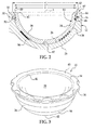
- FIG. 3 is a perspective view of a liner assembly of the prosthetic joint assembly of FIG. 1 ;
- FIG. 4 is a sectional view of the liner assembly of FIG. 3 ;
- FIG. 5 is a side view of a bearing member of the liner assembly of FIG. 3 .
- the joint assembly 10 generally includes a shell 12, a liner assembly 14, and a ring member 16.
- the joint assembly 10 is a hip joint prosthetic assembly 10; however, the joint assembly 10 could be useful for any suitable joint other than the hip joint.
- the joint assembly 10 can be operably coupled to a femoral component 17 having a head 18, a neck 20, and a stem (not shown).
- the femoral component 17 can be fixed to a resected femur (not shown), and the head 18 can be received by the liner assembly 14. More specifically, the head 18 can be movably coupled to the liner assembly 14 for pivotal movement therein.
- the shell 12 can be received in and fixedly coupled to a pelvis 22 within an acetabulum 23 thereof.
- the shell 12 is fixed to the pelvis 22 via one or more fasteners 24.
- the shell 12 includes one or more apertures 25 ( FIG. 1 ), and the fasteners 24 extend through corresponding apertures 25 to attach the shell 12 to the pelvis 22.
- bone cement, adhesive, etc. (not shown) is used to fix the shell 12 to the pelvis 22.
- both fasteners 24 and bone cement, adhesive, etc. is used for this purpose.
- the shell 12 can be fixed to the pelvis 22 in any suitable manner.
- the shell 12 receives the liner assembly 14 in a manner to be discussed in greater detail below.
- the shell 12 can have a dome-like shape so as to include an inner surface 26 (i.e., bearing-engaging surface) and an outer surface 28 (i.e., bone engaging surface).
- the outer surface 28 can be relatively porous to facilitate fixation of the shell 12 to the pelvis 22.
- the apertures 25 can be countersunk on the inner surface 26 to allow the fasteners 24 to be disposed beneath the inner surface 26 when used to attach the shell 12 to the pelvis 22.
- the shell 12 includes an axis X.
- the shell 12 includes a rim 30 and a groove 32. In some embodiments, the groove 32 is annular and extends inwardly from the inner surface 26, transverse to the axis X, and adjacent the rim 30.
- the shell 12 can be made out of any suitable material.
- the shell 12 is made out of metal, such as cobalt, chrome, titanium, titanium alloy, etc.
- the shell 12 is made out of a ceramic material.
- the shell 12 can be made using any suitable manufacturing process. For instance, in some embodiments, the shell 12 is cast or wrought.
- the ring member 16 is substantially flat and annular. In some embodiments represented in FIG. 1 , the ring member 16 is notched so as to be discontinuous. As shown in FIG. 2 , the ring member 16 defines an inner width W and an outer width W'. Because the ring member 16 is notched, the ring member 16 can flex so as to change the inner width W and an outer width W'.
- the liner assembly 14 includes a bearing member 34.
- the bearing member 34 can have a dome-like shape so as to include an outer surface 36 (i.e., shell-engaging surface), an inner surface 38 (i.e., articulating surface), and a rim 40.
- the bearing member 34 can include a radius 41 formed on the inner surface 38 adjacent the rim 40. In some embodiments, the radius can measure between approximately .050 and approximately .250 inches.
- the bearing member 34 can include an apex 42. In some embodiments, the bearing member 34 substantially shares the axis X with the shell 12.
- the bearing member 34 can include a first recess 44 and a second recess 46 ( FIG. 5 ).
- the first and second recesses 44, 46 are both annular.
- the first recess 44 can be disposed adjacent the rim 40 of the bearing member 34.
- the second recess 46 can be disposed between the rim 40 and the apex 42 of the bearing member 34.
- the first recess 44 can include a lower lip 45.
- the lower lip 45 has a width W" as shown in FIG. 2 .
- the liner assembly 14 can include a first compressible member 50.
- the first compressible member 50 can be substantially annular and can be disposed in the first recess 44 and can extend about the rim 40 of the bearing member 34.
- the first compressible member 50 can include an outer portion 52 ( FIG. 4 ), which extends out from the first recess 44. It will be appreciated that the first compressible member 50 covers only a portion of the outer surface 36 of the bearing member 34.
- the first compressible member 50 is rigidly fixed to the bearing member 34.
- the first compressible member 50 can also include a groove 54.
- the groove 54 is annular and is disposed in and extends about the first recess 44 as illustrated in FIG. 4 . As will be discussed, the groove 54 receives the ring member 16 to thereby operatively secure the liner assembly 14 to the shell 12.
- the liner assembly 14 can include a second compressible member 56.
- the second compressible member 56 is annular in shape and is disposed in the second recess 46.
- the second compressible member 56 can include an outer portion 58, which extends out from the second recess 46. It will be appreciated that the second compressible member 56 covers only a portion of the outer surface 36 of the bearing member 34.
- the second compressible member 56 is rigidly fixed to the bearing member 34.
- the first and second compressible members 50, 56 can be made out of any suitable material.
- the first and/or second compressible members 50, 56 are made out of a polymeric material, such as polyethylene or PEEK.
- the first and second compressible members 50, 56 are made of a material that is different from the bearing member 34 and the shell 12.
- the first and second compressible members 50, 56 have a modulus of elasticity that is lower than that of the bearing member 34 and the shell 12. As such, the compressible members 50, 56 can deflect and/or deform for achieving a stronger fit between the shell 12 and the liner assembly 14 as will be discussed.
- first and second compressible members 50, 56 can be coupled to the bearing member 34 in using any suitable manufacturing process.
- the first and second compressible members 50, 56 are injection molded or direct compression molded to the bearing member 34.
- the recesses 44, 46 can be dove-tailed or otherwise undercut in order to enhance engagement between the compressible members 50, 56 and the bearing member 34.
- the outer surface 36 can have a roughened, textured surface within the recesses 44, 46 to facilitate engagement with the compressible members 50, 56.
- the compressible members 50, 56 can be fixed to the bearing member 34 via an adhesive.
- the first and second compressible members 50, 56 could be fixed to the shell 12 instead of the bearing member 34.
- the assembly of the prosthetic joint assembly 10 will be discussed in greater detail.
- the shell 12, the liner assembly 14, the ring member 16, and the femoral component 17 are each individually chosen according to anatomical dimensions of the patient and/or according to other factors.
- the shell 12 is fixed to the pelvis 22.
- the shell 12 can be fixed to the pelvis 22 within the acetabulum 23 via fasteners 24 and/or bone cement, adhesive, etc.
- the ring member 16 is advanced axially into the groove 32 of the shell 12.
- the liner assembly 14 is advanced along the axis X into the shell 12 so that the shell 12 receives the liner assembly 14 and the inner surface 26 of the shell 12 is adjacent the outer surface 36 of the liner assembly 14.
- the ring member 16 can resiliently flex to a wider width W until the liner assembly 14 advances enough to allow the ring member 16 to move into the groove 54 of the first compressible member 50.
- the ring member 16 operatively secures the liner assembly 14 and the shell 12 together such that the liner assembly 14 is limited from movement along the axis X away from the shell 12.
- the ring member 16 can abut against both the liner assembly 14 and the shell 12 to substantially eliminate relative movement between the shell 12 and the liner assembly 14 for a secure fit.
- the lower lip 45 of the bearing member 34 has a width W" that is larger than the inner width W of the ring member 16. Accordingly, the bearing member 34 can reinforce the first compressible member 50 for maintaining the tight fit between the shell 12 and the liner assembly 14.
- first and second compressible members 50, 56 can compress, deform and/or deflect due to abutment against the inner surface 26 of the shell 12.
- first and second compressible members 50, 56 can bias against the shell 12 and substantially eliminate any existing gaps between the inner surface 26 of the shell 12 and the outer surface 36 of the bearing member 34 to substantially eliminate micro-motion therebetween.
- the first and second compressible member 50, 56 can make the fit tighter between the shell 12 and the liner assembly 14, and can help to more effectively distribute loads between the shell 12 and the liner assembly 14.
- the first and second compressible members 50, 56 can substantially fill any resultant gaps between the liner assembly 14 and the shell 12.
- the femoral component 17, having already been attached to the femur is coupled to the liner assembly 14. More specifically, the head 18 of the femoral component 17 is movably coupled to the liner assembly 14. As such, the head 18 articulates against the inner surface 38 of the liner assembly 14. It will be appreciated that the radius 41 of the bearing member 34 can effectively distribute any loads or stresses due to impingement between the neck 20 of the femoral component 17 and the liner assembly 14. As such, the liner assembly 14 is more likely to remain coupled to the shell 12, and the femoral component 17 is less likely to be notched due to impingement against the liner assembly 14.
- the joint assembly 10 also includes an anti-rotation device 60.
- the anti-rotation device 60 includes a plurality of recessed surfaces 62 and a plurality of projections 64.
- the recessed surfaces 62 are included on the rim 40 of the bearing member 34, and the projections 64 are fixed to the rim 40 of the shell 12.
- the recessed surfaces 62 could be included on the shell 12 and the projections 64 could be included on the bearing member 34.
- the recessed surfaces 62 extend inwardly and transversely from the axis X on the liner assembly 14, and the plurality of recessed surfaces 62 are spaced evenly about the rim 40 of the bearing member 34.
- the projections 64 are fixed to and extend toward the axis X from the rim 40 of the shell 12, and the projections 64 are evenly spaced about the rim 40 of the shell 12.
- the first compressible member 50 is coupled to the bearing member 34 so as to substantially cover each of the recessed surfaces 62.
- the liner assembly 14 presses into the shell 12, and the recessed surfaces 62 receive corresponding projections 64.
- the first compressible member 50 is disposed between the projections 64 and the recessed surfaces 62.
- the first compressible member 50 compresses and deflects enough to allow for a press fit between the projections 64 and the recessed surfaces 62.
- the first compressible member 50 biases against the shell 12 to substantially eliminate micro-motion therebetween.
- abutment between the projections 64 and the recessed surfaces 62 substantially limit rotation about the axis X, and the first compressible member 50 provides a substantially tight fit between the shell 12 and the liner assembly 14.
- the recessed surfaces 62 substantially reinforce the first compressible member 50 so as to better distribute loads between the liner assembly 14 and the shell 12.
- the prosthetic joint assembly 10 provides a high-strength coupling between the shell 12 and the liner assembly 14.
- the shell 12 can be tightly secured to the liner assembly 14, for instance, even if the shell 12 is deformed when being coupled to the pelvis 22.
- the first and second compressible members 50, 56 can deflect and/or deform in order to maintain the tight fit between the shell 12 and the liner assembly 14.
- the shell 12 and liner assembly 14 can be rigidly secured with the ring member 16 and the anti-rotation device 60 for ease of installation.
- the bearing member 34 can have a greater thickness than comparable devices of the current art because the recesses 44, 46 are localized, and because of this thickness, the bearing member 34 can be easier to manufacture within predetermined tolerances.
Abstract
Description
- This invention relates to a prosthetic joint and, more particularly, to a metal-on-metal modular hybrid liner for a prosthetic joint.
- The statements in this section merely provide background information related to the present disclosure and may not constitute prior art.
- Prosthetic joints can reduce pain due to arthritis, deterioration, deformation, and the like. For instance, hip joint prosthetic assemblies often include femoral components (i.e., components attached to a resected femur) and pelvic components (i.e., components attached to a pelvis), and the femoral components are movably coupled to the pelvic components to replicate the mechanics of the anatomical hip joint. More specifically, pelvic components of a hip joint prosthetic assembly can include a shell and a liner. The shell fixes to the patient's pelvis, within the acetabulum, and the shell receives the liner. The liner fixes to the shell and is coupled to a head of the femoral component of the prosthesis. Accordingly, the liner receives the head of the femoral component, and the head articulates on an inner surface of the liner.
- Oftentimes, the shell and liner are secured against relative rotational movement by a taper lock. Furthermore, in some assemblies, the shell and liner are retained using a ring lock feature. Specifically, a ring member affixes to one or both of the shell and the liner and interferes with movement of the liner axially away from and out of the shell. Additionally, some prosthesis assemblies include a polymeric inner member disposed between the shell and the liner. The inner member covers the outer surface of the liner and can resiliently flex when being inserted into the shell to provide an adequate fit.
- A prosthetic joint assembly is disclosed. The assembly includes a shell including an inner surface. The assembly also includes a bearing member including an outer surface. The bearing member is received by the shell such that the outer surface of the bearing member is adjacent the inner surface of the shell. Furthermore, the joint assembly includes a compressible member that is rigidly fixed to the inner surface of the shell or the outer surface of the bearing member to only cover a portion thereof. The compressible member is made of a material that is different from the shell or the bearing member.
- In another aspect, a liner assembly of a prosthetic joint assembly is disclosed. The joint assembly includes a ring member and a shell that includes an inner surface with a groove that receives the ring member. The liner assembly includes a bearing member that includes an outer surface. The bearing member is received by the shell such that the outer surface of the bearing member is adjacent the inner surface of the shell. Furthermore, the liner assembly includes a compressible member that is rigidly fixed to the outer surface of the bearing member. The compressible member is made of a material that is different than that of the bearing member. The compressible member includes a groove that receives the ring member to limit relative movement between the bearing member and the shell.
- In still another aspect, a prosthetic joint assembly is disclosed. The assembly includes a shell made out of a metallic material or a ceramic material. The joint assembly also includes a bearing member that is made out of a metallic material or a ceramic material. The bearing member is received by the shell. Furthermore, the joint assembly includes an anti-rotation device that includes a protrusion and a recessed surface. The protrusion is fixed to the shell or the bearing member, and the recessed surface is included in the other of the shell and the bearing member. The recessed surface receives the protrusion to limit relative rotation between the shell and the bearing member.
- Still further, a method of implanting a prosthesis assembly is disclosed in another aspect. The method includes selecting a shell that includes a groove. The method also includes selecting a liner assembly that includes a bearing member and a compressible member. The compressible member is rigidly fixed to an outer surface of the bearing member. The compressible member only partially covers the outer surface and includes a groove. The compressible member is made out of a material that is different from the bearing member. Furthermore, the method includes securing the liner assembly within the shell with a ring member such that the ring member is disposed within the groove of the shell and the groove of the compressible member.
- Moreover, a prosthetic joint assembly is disclosed in still another aspect. The joint assembly includes a metallic shell including an inner surface, a groove, and a rim. The joint assembly also includes a metallic bearing member including an outer surface, a rim, and an apex. The bearing member is received by the shell such that the outer surface of the bearing member is adjacent the inner surface of the shell. Furthermore, the joint assembly includes an anti-rotation device that includes a projection that projects from the rim of the shell and a recessed surface included on the rim of the bearing member. The projection is received by the recessed surface to limit relative rotation between the bearing member and the shell. Furthermore, the joint assembly includes a first annular polymeric compressible member that is rigidly fixed to the outer surface of the bearing member on the rim. The first compressible member includes a groove, and the first compressible member is disposed between the recessed surface and the projection. The first compressible member also has a modulus of elasticity lower than that of the shell and the bearing member. Furthermore, the joint assembly includes a second annular polymeric compressible member that is rigidly fixed to the outer surface of the bearing member between the rim and the apex. The second compressible member also has a modulus of elasticity lower than that of the shell and the bearing member. In addition, the joint assembly includes a ring member that is disposed within the groove of the shell and the groove of the first compressible member. The ring member limits actual movement of the bearing member away from the shell.
- Further areas of applicability will become apparent from the description provided herein. It should be understood that the description and specific examples are intended for purposes of illustration only and are not intended to limit the scope of the present disclosure.
- The drawings described herein are for illustration purposes only and are not intended to limit the scope of the present disclosure in any way.
-
FIG. 1 is an exploded view of a prosthetic joint assembly according to various embodiments of the present disclosure; -
FIG. 2 is a sectional view of the prosthetic joint assembly ofFIG. 1 ; -
FIG. 3 is a perspective view of a liner assembly of the prosthetic joint assembly ofFIG. 1 ; -
FIG. 4 is a sectional view of the liner assembly ofFIG. 3 ; and -
FIG. 5 is a side view of a bearing member of the liner assembly ofFIG. 3 . - The following description is merely exemplary in nature and is not intended to limit the present disclosure, application, or uses. It should be understood that throughout the drawings, corresponding reference numerals indicate like or corresponding parts and features.
- Referring initially to
FIGS. 1 and2 , a prostheticjoint assembly 10 is illustrated. Thejoint assembly 10 generally includes ashell 12, aliner assembly 14, and aring member 16. In the embodiment shown, for instance, thejoint assembly 10 is a hip jointprosthetic assembly 10; however, thejoint assembly 10 could be useful for any suitable joint other than the hip joint. Thejoint assembly 10 can be operably coupled to afemoral component 17 having ahead 18, aneck 20, and a stem (not shown). Thefemoral component 17 can be fixed to a resected femur (not shown), and thehead 18 can be received by theliner assembly 14. More specifically, thehead 18 can be movably coupled to theliner assembly 14 for pivotal movement therein. - Furthermore, the
shell 12 can be received in and fixedly coupled to apelvis 22 within anacetabulum 23 thereof. In some embodiments, theshell 12 is fixed to thepelvis 22 via one ormore fasteners 24. More specifically, theshell 12 includes one or more apertures 25 (FIG. 1 ), and thefasteners 24 extend throughcorresponding apertures 25 to attach theshell 12 to thepelvis 22. In other embodiments, bone cement, adhesive, etc. (not shown) is used to fix theshell 12 to thepelvis 22. Moreover, in some embodiments, bothfasteners 24 and bone cement, adhesive, etc. (not shown) is used for this purpose. However, it will be appreciated that theshell 12 can be fixed to thepelvis 22 in any suitable manner. In addition, theshell 12 receives theliner assembly 14 in a manner to be discussed in greater detail below. - The
shell 12 can have a dome-like shape so as to include an inner surface 26 (i.e., bearing-engaging surface) and an outer surface 28 (i.e., bone engaging surface). Theouter surface 28 can be relatively porous to facilitate fixation of theshell 12 to thepelvis 22. Also, theapertures 25 can be countersunk on theinner surface 26 to allow thefasteners 24 to be disposed beneath theinner surface 26 when used to attach theshell 12 to thepelvis 22. Moreover, theshell 12 includes an axis X. Furthermore, theshell 12 includes arim 30 and agroove 32. In some embodiments, thegroove 32 is annular and extends inwardly from theinner surface 26, transverse to the axis X, and adjacent therim 30. - The
shell 12 can be made out of any suitable material. For instance, in some embodiments, theshell 12 is made out of metal, such as cobalt, chrome, titanium, titanium alloy, etc. Also, in some embodiments, theshell 12 is made out of a ceramic material. Theshell 12 can be made using any suitable manufacturing process. For instance, in some embodiments, theshell 12 is cast or wrought. - Furthermore, in some embodiments, the
ring member 16 is substantially flat and annular. In some embodiments represented inFIG. 1 , thering member 16 is notched so as to be discontinuous. As shown inFIG. 2 , thering member 16 defines an inner width W and an outer width W'. Because thering member 16 is notched, thering member 16 can flex so as to change the inner width W and an outer width W'. - Now referring generally to
FIGS. 1-5 , theliner assembly 14 will be discussed in greater detail. Theliner assembly 14 includes a bearingmember 34. The bearingmember 34 can have a dome-like shape so as to include an outer surface 36 (i.e., shell-engaging surface), an inner surface 38 (i.e., articulating surface), and arim 40. Furthermore, the bearingmember 34 can include aradius 41 formed on theinner surface 38 adjacent therim 40. In some embodiments, the radius can measure between approximately .050 and approximately .250 inches. Additionally, the bearingmember 34 can include an apex 42. In some embodiments, the bearingmember 34 substantially shares the axis X with theshell 12. - Moreover, in some embodiments, the bearing
member 34 can include afirst recess 44 and a second recess 46 (FIG. 5 ). In the embodiments represented inFIG. 5 , the first andsecond recesses first recess 44 can be disposed adjacent therim 40 of the bearingmember 34. Thesecond recess 46 can be disposed between therim 40 and the apex 42 of the bearingmember 34. Furthermore, thefirst recess 44 can include alower lip 45. Thelower lip 45 has a width W" as shown inFIG. 2 . - Furthermore, as shown in
FIGS. 2 and4 , theliner assembly 14 can include a firstcompressible member 50. The firstcompressible member 50 can be substantially annular and can be disposed in thefirst recess 44 and can extend about therim 40 of the bearingmember 34. Furthermore, the firstcompressible member 50 can include an outer portion 52 (FIG. 4 ), which extends out from thefirst recess 44. It will be appreciated that the firstcompressible member 50 covers only a portion of theouter surface 36 of the bearingmember 34. Furthermore, in some embodiments, the firstcompressible member 50 is rigidly fixed to the bearingmember 34. - The first
compressible member 50 can also include agroove 54. In some embodiments, thegroove 54 is annular and is disposed in and extends about thefirst recess 44 as illustrated inFIG. 4 . As will be discussed, thegroove 54 receives thering member 16 to thereby operatively secure theliner assembly 14 to theshell 12. - Additionally, the
liner assembly 14 can include a secondcompressible member 56. In some embodiments, the secondcompressible member 56 is annular in shape and is disposed in thesecond recess 46. Moreover, as shown inFIG. 4 , the secondcompressible member 56 can include anouter portion 58, which extends out from thesecond recess 46. It will be appreciated that the secondcompressible member 56 covers only a portion of theouter surface 36 of the bearingmember 34. Moreover, in some embodiments, the secondcompressible member 56 is rigidly fixed to the bearingmember 34. - The first and second
compressible members compressible members compressible members member 34 and theshell 12. Furthermore, in some embodiments, the first and secondcompressible members member 34 and theshell 12. As such, thecompressible members shell 12 and theliner assembly 14 as will be discussed. - Additionally, the first and second
compressible members member 34 in using any suitable manufacturing process. For instance, in some embodiments, the first and secondcompressible members member 34. Therecesses compressible members member 34. Also, theouter surface 36 can have a roughened, textured surface within therecesses compressible members compressible members member 34 via an adhesive. Moreover, it will be appreciated that the first and secondcompressible members shell 12 instead of the bearingmember 34. - Accordingly, referring to
FIGS. 1 and2 , the assembly of the prostheticjoint assembly 10 will be discussed in greater detail. Initially, theshell 12, theliner assembly 14, thering member 16, and thefemoral component 17 are each individually chosen according to anatomical dimensions of the patient and/or according to other factors. Then, theshell 12 is fixed to thepelvis 22. As mentioned above, theshell 12 can be fixed to thepelvis 22 within theacetabulum 23 viafasteners 24 and/or bone cement, adhesive, etc. Then, thering member 16 is advanced axially into thegroove 32 of theshell 12. - Subsequently, the
liner assembly 14 is advanced along the axis X into theshell 12 so that theshell 12 receives theliner assembly 14 and theinner surface 26 of theshell 12 is adjacent theouter surface 36 of theliner assembly 14. It will be appreciated that thering member 16 can resiliently flex to a wider width W until theliner assembly 14 advances enough to allow thering member 16 to move into thegroove 54 of the firstcompressible member 50. Once thering member 16 is disposed in thegroove 54 of the firstcompressible member 50 and thegroove 32 of theshell 12, thering member 16 operatively secures theliner assembly 14 and theshell 12 together such that theliner assembly 14 is limited from movement along the axis X away from theshell 12. Furthermore, when thering member 16 is disposed in thegrooves ring member 16 can abut against both theliner assembly 14 and theshell 12 to substantially eliminate relative movement between theshell 12 and theliner assembly 14 for a secure fit. - Furthermore, it will be appreciated that the
lower lip 45 of the bearingmember 34 has a width W" that is larger than the inner width W of thering member 16. Accordingly, the bearingmember 34 can reinforce the firstcompressible member 50 for maintaining the tight fit between theshell 12 and theliner assembly 14. - In addition, it will be appreciated that the first and second
compressible members inner surface 26 of theshell 12. As such, the first and secondcompressible members shell 12 and substantially eliminate any existing gaps between theinner surface 26 of theshell 12 and theouter surface 36 of the bearingmember 34 to substantially eliminate micro-motion therebetween. As such, the first and secondcompressible member shell 12 and theliner assembly 14, and can help to more effectively distribute loads between theshell 12 and theliner assembly 14. Also, if, for instance, theshell 12 was deformed while being fixed to thepelvis 22, the first and secondcompressible members liner assembly 14 and theshell 12. - Next, the
femoral component 17, having already been attached to the femur (not shown), is coupled to theliner assembly 14. More specifically, thehead 18 of thefemoral component 17 is movably coupled to theliner assembly 14. As such, thehead 18 articulates against theinner surface 38 of theliner assembly 14. It will be appreciated that theradius 41 of the bearingmember 34 can effectively distribute any loads or stresses due to impingement between theneck 20 of thefemoral component 17 and theliner assembly 14. As such, theliner assembly 14 is more likely to remain coupled to theshell 12, and thefemoral component 17 is less likely to be notched due to impingement against theliner assembly 14. - As shown in
FIGS. 1 ,2, and 3 , thejoint assembly 10 also includes ananti-rotation device 60. Generally speaking, theanti-rotation device 60 includes a plurality of recessedsurfaces 62 and a plurality ofprojections 64. In the embodiment shown, the recessed surfaces 62 are included on therim 40 of the bearingmember 34, and theprojections 64 are fixed to therim 40 of theshell 12. However, it will be appreciated that the recessed surfaces 62 could be included on theshell 12 and theprojections 64 could be included on the bearingmember 34. - In the embodiments illustrated in
FIGS. 1 ,2, and 3 , the recessed surfaces 62 extend inwardly and transversely from the axis X on theliner assembly 14, and the plurality of recessedsurfaces 62 are spaced evenly about therim 40 of the bearingmember 34. Also, theprojections 64 are fixed to and extend toward the axis X from therim 40 of theshell 12, and theprojections 64 are evenly spaced about therim 40 of theshell 12. Furthermore, the firstcompressible member 50 is coupled to the bearingmember 34 so as to substantially cover each of the recessed surfaces 62. - During assembly, the
liner assembly 14 presses into theshell 12, and the recessed surfaces 62 receive correspondingprojections 64. It will be appreciated that the firstcompressible member 50 is disposed between theprojections 64 and the recessed surfaces 62. The firstcompressible member 50 compresses and deflects enough to allow for a press fit between theprojections 64 and the recessed surfaces 62. As such, the firstcompressible member 50 biases against theshell 12 to substantially eliminate micro-motion therebetween. Also, abutment between theprojections 64 and the recessed surfaces 62 substantially limit rotation about the axis X, and the firstcompressible member 50 provides a substantially tight fit between theshell 12 and theliner assembly 14. Also, it will be appreciated that the recessed surfaces 62 substantially reinforce the firstcompressible member 50 so as to better distribute loads between theliner assembly 14 and theshell 12. - In summary, the prosthetic
joint assembly 10 provides a high-strength coupling between theshell 12 and theliner assembly 14. Theshell 12 can be tightly secured to theliner assembly 14, for instance, even if theshell 12 is deformed when being coupled to thepelvis 22. Furthermore, the first and secondcompressible members shell 12 and theliner assembly 14. Also, theshell 12 andliner assembly 14 can be rigidly secured with thering member 16 and theanti-rotation device 60 for ease of installation. Moreover, it will be appreciated that the bearingmember 34 can have a greater thickness than comparable devices of the current art because therecesses member 34 can be easier to manufacture within predetermined tolerances. - Moreover, the foregoing discussion discloses and describes merely exemplary embodiments of the present disclosure. One skilled in the art will readily recognize from such discussion, and from the accompanying drawings and claims, that various changes, modifications and variations may be made therein without departing from the spirit and scope of the disclosure as defined in the following claims. For instance, the sequence of the blocks of the method described herein can be changed without departing from the scope of the present disclosure.
The present application claims priority fromUS application number 12/329651US 12/329651 - Statement 1. A prosthetic joint assembly (10) comprising:
- a shell (12) including an inner surface (26);
- a bearing member (34) including an outer surface (36), the bearing member (34) being received by the shell (12) such that the outer surface (36) of the bearing member (34) is adjacent the inner surface (26) of the shell (12); and
- a compressible member (50, 56) that is rigidly fixed to one of the inner surface (26) of the shell (12) and the outer surface (36) of the bearing member (34) to only cover a portion thereof, the compressible member (50, 56) being made of a material that is different from the one of the shell (12) and the bearing member (34).
- Statement 2. The prosthetic joint assembly (10) according to statement 1, wherein the bearing member (34) includes a recess (44, 46), and wherein the compressible member (50, 56) is disposed within the recess (44, 46).
- Statement 3. The prosthetic joint assembly (10) according to statement 2, wherein the compressible member (50, 56) extends out of the recess (44, 46).
- Statement 4. The prosthetic joint assembly (10) according to statement 1, wherein the bearing member (34) includes a rim (40), and wherein the compressible member (50) is annular and extends about the rim (40).
- Statement 5. The prosthetic joint assembly (10) according to statement 1, wherein the bearing member (34) includes a rim (40) and an inner radius (41) on the rim (40).
- Statement 6. The prosthetic joint assembly (10) according to statement 1, wherein the bearing member (34) includes at least one of a projection (64) and a recessed surface (62) that limits relative rotation between the shell (12) and the bearing member (34), wherein the compressible member (50) covers the at least one of the projection (64) and the recessed surface (62) so as to be disposed between the shell (12) and the at least one of the projection (64) and the recessed surface (62).
- Statement 7. The prosthetic joint assembly (10) according to statement 1, wherein the bearing member (34) includes an apex (42) and a rim (40), and wherein the compressible member (56) is rigidly fixed to the bearing member (34) between the apex (42) and the rim (40).
- Statement 8. The prosthetic joint assembly (10) according to statement 1, wherein a modulus of elasticity of the compressible member (50, 56) is lower than a modulus of elasticity of the bearing member (34).
- Statement 9. The prosthetic joint assembly (10) according to statement 1, wherein the shell (12) is made of metal, the bearing member (34) is made of a metal, and the compressible member (50, 56) is made of a polymer.
-
Statement 10. The prosthetic joint assembly (10) according to statement 1, wherein the shell (12) includes a groove (32), and wherein the compressible member (50) includes a groove (54), and further comprising a ring member (16) that is received in the groove (32) of the shell (12) and the groove (54) of the compressible member (50). - Statement 11. The prosthetic joint assembly (10) according to statement 1, wherein the bearing member (34) defines a first annular recess (44) and a second annular recess (46), the first and second annular recesses (44, 46) disposed in spaced relationship to each other, and further comprising a first compressible member (50) and a second compressible member (56), the first compressible member (50) being disposed in the first annular recess (44), the first compressible member defining an annular groove (54), and the second compressible member (56) being disposed in the second annular recess (46).
-
Statement 12. A liner assembly of a prosthetic joint assembly having a ring member and a shell that includes an inner surface with a groove that receives the ring member, the liner assembly comprising:- a bearing member that includes an outer surface, the bearing member being received by the shell such that the outer surface of the bearing member is adjacent the inner surface of the shell; and
- a compressible member that is rigidly fixed to the outer surface of the bearing member, the compressible member being made of a material that is different than that of the bearing member, the compressible member including a groove that receives the ring member to limit relative movement between the bearing member and the shell.
- Statement 13. The liner assembly according to
statement 12, wherein the bearing member is made of a metal and the compressible member is made of a polymer. -
Statement 14. The liner assembly according tostatement 12, wherein the bearing member includes a recess, and wherein the compressible member is disposed within the recess such that the groove of the compressible member extends about the recess. - Statement 15. The liner assembly according to
statement 14, wherein the recess includes a lower lip having a width that is greater than an inner width of the ring member. -
Statement 16. A prosthetic joint assembly comprising:- a shell made of at least one of a metallic material and a ceramic material;
- a bearing member that is made of at least one of a metallic material and a ceramic material, the bearing member being received by the shell; and
- an anti-rotation device that includes a protrusion and a recessed surface, the protrusion fixed to one of the shall and the bearing member, the recessed surface included in the other of the shell and the bearing member, the recessed surface receiving the protrusion to limit relative rotation between the shell and the bearing member.
-
Statement 17. The prosthetic joint assembly according tostatement 16, further comprising a compressible member that is rigidly fixed to at least one of the shell and the bearing member so as to be disposed between the protrusion and the recessed surface. -
Statement 18. The prosthetic joint assembly according tostatement 17, wherein the compressible member has a modulus of elasticity that is lower than a modulus of elasticity of the bearing member and a modulus of elasticity of the shell. - Statement 19. The prosthetic implant according to
statement 16, wherein the compressible member covers only a portion of an outer surface of the bearing member. -
Statement 20. A method of implanting a prosthesis assembly comprising:- selecting a shell that includes a groove;
- selecting a liner assembly that includes a bearing member and a compressible member that is rigidly fixed to an outer surface of the bearing member, the compressible member only partially covering the outer surface and including a groove, the compressible member being made out of a material that is different from the bearing member; and
- operatively securing the liner assembly within the shell with a ring member such that the ring member is disposed within the groove of the shell and the groove of the compressible member.
- Statement 21. The method according to
statement 20, further comprising molding the compressible member to rigidly fix the compressible member to the liner assembly. -
Statement 22. A prosthetic joint assembly comprising:- a metallic shell including an inner surface, a groove, and a rim;
- a metallic bearing member including an outer surface, a rim, and an apex, the bearing member being received by the shell such that the outer surface of the bearing member is adjacent the inner surface of the shell;
- an anti-rotation device that includes a projection that projects from the rim of the shell and a recessed surface included on the rim of the bearing member, the projection received by the recessed surface to limit relative rotation between the bearing member and the shell;
- a first annular polymeric compressible member that is rigidly fixed to the outer surface of the bearing member on the rim, the first compressible member including a groove, the first compressible member disposed between the recessed surface and the projection, the first compressible member also having a modulus of elasticity lower than that of the shell and the bearing member;
- a second annular polymeric compressible member that is rigidly fixed to the outer surface of the bearing member between the rim and the apex, the second compressible member also having a modulus of elasticity lower than that of the shell and the bearing member; and
- a ring member that is disposed within the groove of the shell and the groove of the first compressible member, the ring member limiting axial movement of the bearing member away from the shell.
Claims (15)
- A prosthetic joint assembly (10) comprising:a shell (12) including an inner surface (26);a bearing member (34) including an outer surface (36), the bearing member (34) being received by the shell (12) such that the outer surface (36) of the bearing member (34) is adjacent the inner surface (26) of the shell (12); anda compressible member (50, 56) that is rigidly fixed to one of the inner surface (26) of the shell (12) and the outer surface (36) of the bearing member (34) to only cover a portion thereof, the compressible member (50, 56) being made of a material that is different from the one of the shell (12) and the bearing member (34).
- A prosthetic joint assembly (10) comprising:a shell (12) made of at least one of a metallic material and a ceramic material;a bearing member (34) that is made of at least one of a metallic material and a ceramic material, the bearing member (34) being received by the shell (12); andan anti-rotation device (60) that includes a protrusion (64) and a recessed surface (62), the protrusion (64) fixed to one of the shell (12) and the bearing member (34), the recessed surface (62) included in the other of the shell (12) and the bearing member (34), the recessed surface (62) receiving the protrusion (64) to limit relative rotation between the shell (12) and the bearing member (34).
- The prosthetic joint assembly (10) of claim 2, further comprising a compressible member (50, 56) that is rigidly fixed to at least one of the shell (12) and the bearing member (34) so as to be disposed between the protrusion (64) and the recessed surface (62).
- The prosthetic joint assembly (10) of claim 1 or 3, wherein the bearing member (34) includes a recess (44, 46), and wherein the compressible member (50, 56) is disposed within the recess (44, 46).
- The prosthetic joint assembly (10) of claim 4, wherein the compressible member (50, 56) extends out of the recess (44, 46).
- The prosthetic joint assembly (10) of claim 1 or 3, wherein the bearing member (34) includes a rim (40), and wherein the compressible member (50) is annular and extends about the rim (40).
- The prosthetic joint assembly (10) of claim 1 or 2, wherein the bearing member (34) includes a rim (40) and an inner radius (41) on the rim (40).
- The prosthetic joint assembly (10) of claim 1, wherein the bearing member (34) includes at least one of a projection (64) and a recessed surface (62) that limits relative rotation between the shell (12) and the bearing member (34), wherein the compressible member (50) covers the at least one of the projection (64) and the recessed surface (62) so as to be disposed between the shell (12) and the at least one of the projection (64) and the recessed surface (62).
- The prosthetic joint assembly (10) of claim 1 or 3, wherein the bearing member (34) includes an apex (42) and a rim (40), and wherein the compressible member (56) is rigidly fixed to the bearing member (34) between the apex (42) and the rim (40).
- The prosthetic joint assembly (10) of claim 1 or 3, wherein a modulus of elasticity of the compressible member (50, 56) is lower than a modulus of elasticity of the bearing member (34).
- The prosthetic joint assembly (10) of claim 1 or 3, wherein the shell (12) is made of metal, the bearing member (34) is made of a metal, and the compressible member (50, 56) is made of a polymer.
- The prosthetic joint assembly (10) of claim 1 or 3, wherein the shell (12) includes a groove (32), and wherein the compressible member (50) includes a groove (54), and further comprising a ring member (16) that is received in the groove (32) of the shell (12) and the groove (54) of the compressible member (50).
- The prosthetic joint assembly (10) of claim 1, 3, or 10, wherein the bearing member (34) defines a first annular recess (44) and a second annular recess (46), the first and second annular recesses (44, 46) disposed in spaced relationship to each other, the compressible member including a first compressible member (50) and a second compressible member (56), the first compressible member (50) being disposed in the first annular recess (44), the first compressible member defining an annular groove (54), and the second compressible member (56) being disposed in the second annular recess (46).
- The prosthetic joint assembly (10) of claim 13, wherein the groove (54) of the first compressible member (50) extends about the recess (44).
- The prosthetic joint assembly (10) of claim 14, wherein the recess (44) includes a lower lip (45) having a width (W") that is greater than an inner width (W) of the ring member (16).
Applications Claiming Priority (1)
| Application Number | Priority Date | Filing Date | Title |
|---|---|---|---|
| US12/329,651 US8007539B2 (en) | 2008-12-08 | 2008-12-08 | Metal-on-metal modular hybrid liner |
Publications (2)
| Publication Number | Publication Date |
|---|---|
| EP2193764A1 true EP2193764A1 (en) | 2010-06-09 |
| EP2193764B1 EP2193764B1 (en) | 2013-09-18 |
Family
ID=41818776
Family Applications (1)
| Application Number | Title | Priority Date | Filing Date |
|---|---|---|---|
| EP09178414.0A Not-in-force EP2193764B1 (en) | 2008-12-08 | 2009-12-08 | Metal-on-metal modular hybrid liner |
Country Status (4)
| Country | Link |
|---|---|
| US (1) | US8007539B2 (en) |
| EP (1) | EP2193764B1 (en) |
| JP (1) | JP2010131398A (en) |
| CN (1) | CN101756755A (en) |
Cited By (3)
| Publication number | Priority date | Publication date | Assignee | Title |
|---|---|---|---|---|
| US8123815B2 (en) | 2008-11-24 | 2012-02-28 | Biomet Manufacturing Corp. | Multiple bearing acetabular prosthesis |
| US8308810B2 (en) | 2009-07-14 | 2012-11-13 | Biomet Manufacturing Corp. | Multiple bearing acetabular prosthesis |
| EP3701913A1 (en) * | 2019-02-27 | 2020-09-02 | ImplanTec Deutschland GmbH | Acetabular cup for a hip joint endoprosthesis |
Families Citing this family (34)
| Publication number | Priority date | Publication date | Assignee | Title |
|---|---|---|---|---|
| US8591516B2 (en) | 2006-02-27 | 2013-11-26 | Biomet Manufacturing, Llc | Patient-specific orthopedic instruments |
| US9345548B2 (en) | 2006-02-27 | 2016-05-24 | Biomet Manufacturing, Llc | Patient-specific pre-operative planning |
| US9173661B2 (en) | 2006-02-27 | 2015-11-03 | Biomet Manufacturing, Llc | Patient specific alignment guide with cutting surface and laser indicator |
| US10278711B2 (en) | 2006-02-27 | 2019-05-07 | Biomet Manufacturing, Llc | Patient-specific femoral guide |
| US8603180B2 (en) | 2006-02-27 | 2013-12-10 | Biomet Manufacturing, Llc | Patient-specific acetabular alignment guides |
| US8407067B2 (en) | 2007-04-17 | 2013-03-26 | Biomet Manufacturing Corp. | Method and apparatus for manufacturing an implant |
| US8608749B2 (en) * | 2006-02-27 | 2013-12-17 | Biomet Manufacturing, Llc | Patient-specific acetabular guides and associated instruments |
| US20150335438A1 (en) | 2006-02-27 | 2015-11-26 | Biomet Manufacturing, Llc. | Patient-specific augments |
| US9907659B2 (en) | 2007-04-17 | 2018-03-06 | Biomet Manufacturing, Llc | Method and apparatus for manufacturing an implant |
| US8568487B2 (en) | 2006-02-27 | 2013-10-29 | Biomet Manufacturing, Llc | Patient-specific hip joint devices |
| US9113971B2 (en) | 2006-02-27 | 2015-08-25 | Biomet Manufacturing, Llc | Femoral acetabular impingement guide |
| US9289253B2 (en) | 2006-02-27 | 2016-03-22 | Biomet Manufacturing, Llc | Patient-specific shoulder guide |
| US9918740B2 (en) | 2006-02-27 | 2018-03-20 | Biomet Manufacturing, Llc | Backup surgical instrument system and method |
| US9339278B2 (en) | 2006-02-27 | 2016-05-17 | Biomet Manufacturing, Llc | Patient-specific acetabular guides and associated instruments |
| US9795399B2 (en) | 2006-06-09 | 2017-10-24 | Biomet Manufacturing, Llc | Patient-specific knee alignment guide and associated method |
| DE102007031667A1 (en) * | 2006-08-04 | 2008-02-14 | Ceramtec Ag Innovative Ceramic Engineering | Insertion of vibration-damping elements in prosthetic systems for manipulation and damping of natural frequencies |
| US8308812B2 (en) | 2006-11-07 | 2012-11-13 | Biomedflex, Llc | Prosthetic joint assembly and joint member therefor |
| US8512413B2 (en) | 2006-11-07 | 2013-08-20 | Biomedflex, Llc | Prosthetic knee joint |
| US9005307B2 (en) | 2006-11-07 | 2015-04-14 | Biomedflex, Llc | Prosthetic ball-and-socket joint |
| US20110166671A1 (en) | 2006-11-07 | 2011-07-07 | Kellar Franz W | Prosthetic joint |
| DE102008047627A1 (en) * | 2008-08-01 | 2010-02-04 | Smith & Nephew Orthopaedics Ag | Positioning aid in the form of a self-fixing trial acetabulum |
| US8840676B2 (en) * | 2009-05-07 | 2014-09-23 | Smith & Nephew, Inc. | Modular trial heads for a prosthetic |
| US11039929B2 (en) * | 2009-07-10 | 2021-06-22 | Peter Mats Forsell | Hip joint device and method |
| CN102985035A (en) * | 2010-05-18 | 2013-03-20 | 史密夫和内修有限公司 | Revision hip implants and prosthesis systems |
| KR20140019764A (en) | 2010-06-08 | 2014-02-17 | 스미스 앤드 네퓨, 인크. | Implant components and methods |
| US9271744B2 (en) | 2010-09-29 | 2016-03-01 | Biomet Manufacturing, Llc | Patient-specific guide for partial acetabular socket replacement |
| US9968376B2 (en) | 2010-11-29 | 2018-05-15 | Biomet Manufacturing, Llc | Patient-specific orthopedic instruments |
| US9241745B2 (en) | 2011-03-07 | 2016-01-26 | Biomet Manufacturing, Llc | Patient-specific femoral version guide |
| CA2837872A1 (en) | 2011-06-03 | 2012-12-06 | Smith & Nephew, Inc. | Prosthesis guide comprising patient-matched features |
| US8597365B2 (en) | 2011-08-04 | 2013-12-03 | Biomet Manufacturing, Llc | Patient-specific pelvic implants for acetabular reconstruction |
| US9386993B2 (en) | 2011-09-29 | 2016-07-12 | Biomet Manufacturing, Llc | Patient-specific femoroacetabular impingement instruments and methods |
| CN105030381A (en) * | 2015-07-03 | 2015-11-11 | 江苏奥康尼医疗科技发展有限公司 | Artificial acetabular cup |
| US10722310B2 (en) | 2017-03-13 | 2020-07-28 | Zimmer Biomet CMF and Thoracic, LLC | Virtual surgery planning system and method |
| CN107569303A (en) * | 2017-09-27 | 2018-01-12 | 北京市春立正达医疗器械股份有限公司 | Full acetabular component |
Citations (5)
| Publication number | Priority date | Publication date | Assignee | Title |
|---|---|---|---|---|
| EP0298234A1 (en) * | 1987-07-09 | 1989-01-11 | GebràDer Sulzer Aktiengesellschaft | Acetabular cup |
| EP0445068A1 (en) * | 1990-03-02 | 1991-09-04 | Gebrüder Sulzer Aktiengesellschaft | Artificial hip cup |
| DE19813074A1 (en) * | 1998-03-25 | 1999-09-30 | Ceram Tec Ag Innovative Cerami | Clamp-fit connection between prosthetic components of joint prostheses |
| WO2001024739A2 (en) * | 1999-10-07 | 2001-04-12 | Exactech, Inc. | Acetabular bearing assembly for total hip joints |
| WO2008130989A2 (en) * | 2007-04-19 | 2008-10-30 | Smith & Nephew, Inc. | Prosthetic implants |
Family Cites Families (29)
| Publication number | Priority date | Publication date | Assignee | Title |
|---|---|---|---|---|
| US2668531A (en) | 1952-02-15 | 1954-02-09 | Edward J Haboush | Prosthesis for hip joint |
| US3067740A (en) | 1959-09-08 | 1962-12-11 | Edward J Haboush | Hip joint prosthesis |
| GB1126961A (en) | 1965-01-14 | 1968-09-11 | Nat Res Dev | Artificial joints for use in surgery |
| US3740769A (en) | 1971-02-11 | 1973-06-26 | E Haboush | Prosthesis for hip joints |
| GB1410598A (en) | 1971-11-30 | 1975-10-22 | Nat Res Dev | Prosthetic shoulder joint devices |
| SU428623A1 (en) | 1972-05-04 | 1976-07-05 | Саратовский государственный медицинский институт | Collapsible artificial hip joint |
| US4619658A (en) | 1982-02-24 | 1986-10-28 | Pappas Michael J | Spherical kinematic joint |
| US6042611A (en) | 1983-03-08 | 2000-03-28 | Joint Medical Products Corporation | Ball and socket bearing for artificial joint |
| US4642123A (en) | 1983-03-08 | 1987-02-10 | Joint Medical Products Corporation | Ball and socket bearing for artificial joint |
| US4978356A (en) | 1983-03-08 | 1990-12-18 | Joint Medical Products Corporation | Ball and socket bearing for artificial joint |
| US4676798A (en) | 1984-09-12 | 1987-06-30 | Joint Medical Products Corporation | Socket bearing assembly for a constrained ball and socket joint |
| NL8700879A (en) | 1987-04-14 | 1988-11-01 | Jan Bernard Mullers | JOINT PROSTHESIS AND JOINT PROSTHESIS ORGANIZATION AND COMBINED ELEMENT FOR APPLICATION IN SUCH A JOINT PROSTHESIS ORGANIZATION. |
| US5019105A (en) | 1989-08-03 | 1991-05-28 | Biomet, Inc. | Acetabular cup prosthesis assembly |
| US5314491A (en) | 1990-02-02 | 1994-05-24 | Zimmer, Inc. | Prosthetic socket implant |
| US5282864A (en) | 1992-02-19 | 1994-02-01 | Joint Medical Products Corporation | Acetabular prosthesis having a metal socket bearing |
| US5425779A (en) | 1992-08-05 | 1995-06-20 | U.S. Medical Products, Inc. | Prosthetic implant for joint structures |
| ATE282376T1 (en) * | 1996-04-23 | 2004-12-15 | Biomet Ltd | METHOD FOR MAKING A HIP JOINT POCKET |
| US5755807A (en) | 1996-06-17 | 1998-05-26 | Folsom Metal Products | Implant module unit and rotating seal for prosthetic joint |
| US20020072805A1 (en) | 1996-08-21 | 2002-06-13 | Sullivan John Martin Patrick | Joint replacement prosthesis |
| US5824108A (en) | 1997-03-26 | 1998-10-20 | Johnson & Johnson Professional, Inc. | Bipolar acetabular cup |
| US5800555A (en) | 1997-04-24 | 1998-09-01 | Depuy Orthopaedics, Inc. | Acetabular cup bearing liner |
| IT245363Y1 (en) | 1998-05-12 | 2002-03-20 | Tian Enrico | ANTI-LUXURY ANKLE PROSTHESIS |
| CA2270861C (en) | 1998-05-22 | 2006-08-29 | Michael B. Sheldon | Acetabular cup assembly with selected bearing |
| US5989293A (en) | 1998-07-17 | 1999-11-23 | Bristol-Myers Squibb Co. | Acetabular cup kit for use during hip replacement surgery |
| AU783205C (en) * | 2000-03-15 | 2006-08-17 | Depuy Orthopaedics, Inc. | Prosthetic cup assembly which includes components possessing self-locking taper |
| DE10036987A1 (en) | 2000-07-29 | 2002-02-07 | Klaus Draenert | Modular pan replacement |
| AU2002327410A1 (en) | 2001-07-31 | 2003-02-17 | Biomet, Inc. | Method and apparatus for constrained liner |
| US6916342B2 (en) | 2002-04-01 | 2005-07-12 | Smith & Nephew, Inc. | Liner assembly for prosthetic components |
| WO2004000159A2 (en) | 2002-06-21 | 2003-12-31 | Massachusetts General Hospital | Metal back or mesh crosslinking |
-
2008
- 2008-12-08 US US12/329,651 patent/US8007539B2/en not_active Expired - Fee Related
-
2009
- 2009-12-08 JP JP2009278389A patent/JP2010131398A/en active Pending
- 2009-12-08 CN CN200910253548A patent/CN101756755A/en active Pending
- 2009-12-08 EP EP09178414.0A patent/EP2193764B1/en not_active Not-in-force
Patent Citations (5)
| Publication number | Priority date | Publication date | Assignee | Title |
|---|---|---|---|---|
| EP0298234A1 (en) * | 1987-07-09 | 1989-01-11 | GebràDer Sulzer Aktiengesellschaft | Acetabular cup |
| EP0445068A1 (en) * | 1990-03-02 | 1991-09-04 | Gebrüder Sulzer Aktiengesellschaft | Artificial hip cup |
| DE19813074A1 (en) * | 1998-03-25 | 1999-09-30 | Ceram Tec Ag Innovative Cerami | Clamp-fit connection between prosthetic components of joint prostheses |
| WO2001024739A2 (en) * | 1999-10-07 | 2001-04-12 | Exactech, Inc. | Acetabular bearing assembly for total hip joints |
| WO2008130989A2 (en) * | 2007-04-19 | 2008-10-30 | Smith & Nephew, Inc. | Prosthetic implants |
Cited By (6)
| Publication number | Priority date | Publication date | Assignee | Title |
|---|---|---|---|---|
| US8123815B2 (en) | 2008-11-24 | 2012-02-28 | Biomet Manufacturing Corp. | Multiple bearing acetabular prosthesis |
| US9445903B2 (en) | 2008-11-24 | 2016-09-20 | Biomet Manufacturing, Llc | Multi-bearing acetabular prosthesis |
| US8308810B2 (en) | 2009-07-14 | 2012-11-13 | Biomet Manufacturing Corp. | Multiple bearing acetabular prosthesis |
| US9445904B2 (en) | 2009-07-14 | 2016-09-20 | Biomet Manufacturing, Llc | Multiple bearing acetabular prosthesis |
| EP3701913A1 (en) * | 2019-02-27 | 2020-09-02 | ImplanTec Deutschland GmbH | Acetabular cup for a hip joint endoprosthesis |
| EP3714840A1 (en) | 2019-02-27 | 2020-09-30 | ARTIQO GmbH | Acetabular cup for a hip joint endoprosthesis |
Also Published As
| Publication number | Publication date |
|---|---|
| JP2010131398A (en) | 2010-06-17 |
| CN101756755A (en) | 2010-06-30 |
| US8007539B2 (en) | 2011-08-30 |
| EP2193764B1 (en) | 2013-09-18 |
| US20100145466A1 (en) | 2010-06-10 |
Similar Documents
| Publication | Publication Date | Title |
|---|---|---|
| US8007539B2 (en) | Metal-on-metal modular hybrid liner | |
| US9713531B2 (en) | Deflection resistant acetabular cup | |
| US6569202B2 (en) | Tray and liner for joint replacement system | |
| US20100179663A1 (en) | Acetabular prosthetic devices | |
| US8834573B2 (en) | Pyrocarbon orthopedic implant | |
| US6527808B1 (en) | Constrained socket for use with a ball-and-socket joint | |
| US20190201205A1 (en) | Compliant anti-resorption implant | |
| EP2574310B1 (en) | Self-centering, anti-seizing acetabular liner | |
| AU2004203341A1 (en) | Hip prosthesis with a modular acetabular cup assembly | |
| EP2161007A1 (en) | Revision patella prosthesis | |
| CN111281610B (en) | Porous structure and connection structure of substrate | |
| EP3484414B1 (en) | Devices and methods for cementing insert bearing liner into acetabular cup component | |
| JP6830995B2 (en) | liner | |
| US20210169654A1 (en) | Metal reinforced acetabular shell liner |
Legal Events
| Date | Code | Title | Description |
|---|---|---|---|
| PUAI | Public reference made under article 153(3) epc to a published international application that has entered the european phase |
Free format text: ORIGINAL CODE: 0009012 |
|
| AK | Designated contracting states |
Kind code of ref document: A1 Designated state(s): AT BE BG CH CY CZ DE DK EE ES FI FR GB GR HR HU IE IS IT LI LT LU LV MC MK MT NL NO PL PT RO SE SI SK SM TR |
|
| AX | Request for extension of the european patent |
Extension state: AL BA RS |
|
| 17P | Request for examination filed |
Effective date: 20101206 |
|
| 17Q | First examination report despatched |
Effective date: 20120116 |
|
| GRAP | Despatch of communication of intention to grant a patent |
Free format text: ORIGINAL CODE: EPIDOSNIGR1 |
|
| INTG | Intention to grant announced |
Effective date: 20130405 |
|
| GRAS | Grant fee paid |
Free format text: ORIGINAL CODE: EPIDOSNIGR3 |
|
| GRAA | (expected) grant |
Free format text: ORIGINAL CODE: 0009210 |
|
| AK | Designated contracting states |
Kind code of ref document: B1 Designated state(s): AT BE BG CH CY CZ DE DK EE ES FI FR GB GR HR HU IE IS IT LI LT LU LV MC MK MT NL NO PL PT RO SE SI SK SM TR |
|
| REG | Reference to a national code |
Ref country code: GB Ref legal event code: FG4D |
|
| REG | Reference to a national code |
Ref country code: CH Ref legal event code: EP |
|
| REG | Reference to a national code |
Ref country code: IE Ref legal event code: FG4D |
|
| REG | Reference to a national code |
Ref country code: AT Ref legal event code: REF Ref document number: 632322 Country of ref document: AT Kind code of ref document: T Effective date: 20131015 |
|
| REG | Reference to a national code |
Ref country code: DE Ref legal event code: R096 Ref document number: 602009018854 Country of ref document: DE Effective date: 20131114 |
|
| PG25 | Lapsed in a contracting state [announced via postgrant information from national office to epo] |
Ref country code: LT Free format text: LAPSE BECAUSE OF FAILURE TO SUBMIT A TRANSLATION OF THE DESCRIPTION OR TO PAY THE FEE WITHIN THE PRESCRIBED TIME-LIMIT Effective date: 20130918 Ref country code: CY Free format text: LAPSE BECAUSE OF FAILURE TO SUBMIT A TRANSLATION OF THE DESCRIPTION OR TO PAY THE FEE WITHIN THE PRESCRIBED TIME-LIMIT Effective date: 20130828 Ref country code: SE Free format text: LAPSE BECAUSE OF FAILURE TO SUBMIT A TRANSLATION OF THE DESCRIPTION OR TO PAY THE FEE WITHIN THE PRESCRIBED TIME-LIMIT Effective date: 20130918 Ref country code: NO Free format text: LAPSE BECAUSE OF FAILURE TO SUBMIT A TRANSLATION OF THE DESCRIPTION OR TO PAY THE FEE WITHIN THE PRESCRIBED TIME-LIMIT Effective date: 20131218 Ref country code: HR Free format text: LAPSE BECAUSE OF FAILURE TO SUBMIT A TRANSLATION OF THE DESCRIPTION OR TO PAY THE FEE WITHIN THE PRESCRIBED TIME-LIMIT Effective date: 20130918 |
|
| REG | Reference to a national code |
Ref country code: NL Ref legal event code: VDEP Effective date: 20130918 |
|
| REG | Reference to a national code |
Ref country code: AT Ref legal event code: MK05 Ref document number: 632322 Country of ref document: AT Kind code of ref document: T Effective date: 20130918 |
|
| REG | Reference to a national code |
Ref country code: LT Ref legal event code: MG4D |
|
| PG25 | Lapsed in a contracting state [announced via postgrant information from national office to epo] |
Ref country code: GR Free format text: LAPSE BECAUSE OF FAILURE TO SUBMIT A TRANSLATION OF THE DESCRIPTION OR TO PAY THE FEE WITHIN THE PRESCRIBED TIME-LIMIT Effective date: 20131219 Ref country code: SI Free format text: LAPSE BECAUSE OF FAILURE TO SUBMIT A TRANSLATION OF THE DESCRIPTION OR TO PAY THE FEE WITHIN THE PRESCRIBED TIME-LIMIT Effective date: 20130918 Ref country code: LV Free format text: LAPSE BECAUSE OF FAILURE TO SUBMIT A TRANSLATION OF THE DESCRIPTION OR TO PAY THE FEE WITHIN THE PRESCRIBED TIME-LIMIT Effective date: 20130918 Ref country code: FI Free format text: LAPSE BECAUSE OF FAILURE TO SUBMIT A TRANSLATION OF THE DESCRIPTION OR TO PAY THE FEE WITHIN THE PRESCRIBED TIME-LIMIT Effective date: 20130918 |
|
| PG25 | Lapsed in a contracting state [announced via postgrant information from national office to epo] |
Ref country code: BE Free format text: LAPSE BECAUSE OF FAILURE TO SUBMIT A TRANSLATION OF THE DESCRIPTION OR TO PAY THE FEE WITHIN THE PRESCRIBED TIME-LIMIT Effective date: 20130918 Ref country code: CY Free format text: LAPSE BECAUSE OF FAILURE TO SUBMIT A TRANSLATION OF THE DESCRIPTION OR TO PAY THE FEE WITHIN THE PRESCRIBED TIME-LIMIT Effective date: 20130918 |
|
| PG25 | Lapsed in a contracting state [announced via postgrant information from national office to epo] |
Ref country code: NL Free format text: LAPSE BECAUSE OF FAILURE TO SUBMIT A TRANSLATION OF THE DESCRIPTION OR TO PAY THE FEE WITHIN THE PRESCRIBED TIME-LIMIT Effective date: 20130918 Ref country code: SK Free format text: LAPSE BECAUSE OF FAILURE TO SUBMIT A TRANSLATION OF THE DESCRIPTION OR TO PAY THE FEE WITHIN THE PRESCRIBED TIME-LIMIT Effective date: 20130918 Ref country code: IS Free format text: LAPSE BECAUSE OF FAILURE TO SUBMIT A TRANSLATION OF THE DESCRIPTION OR TO PAY THE FEE WITHIN THE PRESCRIBED TIME-LIMIT Effective date: 20140118 Ref country code: CZ Free format text: LAPSE BECAUSE OF FAILURE TO SUBMIT A TRANSLATION OF THE DESCRIPTION OR TO PAY THE FEE WITHIN THE PRESCRIBED TIME-LIMIT Effective date: 20130918 Ref country code: EE Free format text: LAPSE BECAUSE OF FAILURE TO SUBMIT A TRANSLATION OF THE DESCRIPTION OR TO PAY THE FEE WITHIN THE PRESCRIBED TIME-LIMIT Effective date: 20130918 |
|
| PG25 | Lapsed in a contracting state [announced via postgrant information from national office to epo] |
Ref country code: AT Free format text: LAPSE BECAUSE OF FAILURE TO SUBMIT A TRANSLATION OF THE DESCRIPTION OR TO PAY THE FEE WITHIN THE PRESCRIBED TIME-LIMIT Effective date: 20130918 Ref country code: PL Free format text: LAPSE BECAUSE OF FAILURE TO SUBMIT A TRANSLATION OF THE DESCRIPTION OR TO PAY THE FEE WITHIN THE PRESCRIBED TIME-LIMIT Effective date: 20130918 Ref country code: ES Free format text: LAPSE BECAUSE OF FAILURE TO SUBMIT A TRANSLATION OF THE DESCRIPTION OR TO PAY THE FEE WITHIN THE PRESCRIBED TIME-LIMIT Effective date: 20130918 |
|
| REG | Reference to a national code |
Ref country code: DE Ref legal event code: R097 Ref document number: 602009018854 Country of ref document: DE |
|
| PG25 | Lapsed in a contracting state [announced via postgrant information from national office to epo] |
Ref country code: PT Free format text: LAPSE BECAUSE OF FAILURE TO SUBMIT A TRANSLATION OF THE DESCRIPTION OR TO PAY THE FEE WITHIN THE PRESCRIBED TIME-LIMIT Effective date: 20140120 |
|
| REG | Reference to a national code |
Ref country code: DE Ref legal event code: R119 Ref document number: 602009018854 Country of ref document: DE |
|
| PLBE | No opposition filed within time limit |
Free format text: ORIGINAL CODE: 0009261 |
|
| STAA | Information on the status of an ep patent application or granted ep patent |
Free format text: STATUS: NO OPPOSITION FILED WITHIN TIME LIMIT |
|
| REG | Reference to a national code |
Ref country code: CH Ref legal event code: PL |
|
| 26N | No opposition filed |
Effective date: 20140619 |
|
| GBPC | Gb: european patent ceased through non-payment of renewal fee |
Effective date: 20131218 |
|
| PG25 | Lapsed in a contracting state [announced via postgrant information from national office to epo] |
Ref country code: LU Free format text: LAPSE BECAUSE OF FAILURE TO SUBMIT A TRANSLATION OF THE DESCRIPTION OR TO PAY THE FEE WITHIN THE PRESCRIBED TIME-LIMIT Effective date: 20131208 Ref country code: IT Free format text: LAPSE BECAUSE OF FAILURE TO SUBMIT A TRANSLATION OF THE DESCRIPTION OR TO PAY THE FEE WITHIN THE PRESCRIBED TIME-LIMIT Effective date: 20130918 Ref country code: MC Free format text: LAPSE BECAUSE OF FAILURE TO SUBMIT A TRANSLATION OF THE DESCRIPTION OR TO PAY THE FEE WITHIN THE PRESCRIBED TIME-LIMIT Effective date: 20130918 |
|
| REG | Reference to a national code |
Ref country code: DE Ref legal event code: R119 Ref document number: 602009018854 Country of ref document: DE Effective date: 20140701 |
|
| REG | Reference to a national code |
Ref country code: IE Ref legal event code: MM4A |
|
| REG | Reference to a national code |
Ref country code: FR Ref legal event code: ST Effective date: 20140829 |
|
| PG25 | Lapsed in a contracting state [announced via postgrant information from national office to epo] |
Ref country code: DK Free format text: LAPSE BECAUSE OF FAILURE TO SUBMIT A TRANSLATION OF THE DESCRIPTION OR TO PAY THE FEE WITHIN THE PRESCRIBED TIME-LIMIT Effective date: 20130918 |
|
| REG | Reference to a national code |
Ref country code: DE Ref legal event code: R097 Ref document number: 602009018854 Country of ref document: DE Effective date: 20140619 |
|
| PG25 | Lapsed in a contracting state [announced via postgrant information from national office to epo] |
Ref country code: LI Free format text: LAPSE BECAUSE OF NON-PAYMENT OF DUE FEES Effective date: 20131231 Ref country code: IE Free format text: LAPSE BECAUSE OF NON-PAYMENT OF DUE FEES Effective date: 20131208 Ref country code: DE Free format text: LAPSE BECAUSE OF NON-PAYMENT OF DUE FEES Effective date: 20140701 Ref country code: CH Free format text: LAPSE BECAUSE OF NON-PAYMENT OF DUE FEES Effective date: 20131231 |
|
| PG25 | Lapsed in a contracting state [announced via postgrant information from national office to epo] |
Ref country code: GB Free format text: LAPSE BECAUSE OF NON-PAYMENT OF DUE FEES Effective date: 20131218 Ref country code: FR Free format text: LAPSE BECAUSE OF NON-PAYMENT OF DUE FEES Effective date: 20131231 |
|
| PG25 | Lapsed in a contracting state [announced via postgrant information from national office to epo] |
Ref country code: RO Free format text: LAPSE BECAUSE OF FAILURE TO SUBMIT A TRANSLATION OF THE DESCRIPTION OR TO PAY THE FEE WITHIN THE PRESCRIBED TIME-LIMIT Effective date: 20130918 |
|
| PG25 | Lapsed in a contracting state [announced via postgrant information from national office to epo] |
Ref country code: SM Free format text: LAPSE BECAUSE OF FAILURE TO SUBMIT A TRANSLATION OF THE DESCRIPTION OR TO PAY THE FEE WITHIN THE PRESCRIBED TIME-LIMIT Effective date: 20130918 |
|
| PG25 | Lapsed in a contracting state [announced via postgrant information from national office to epo] |
Ref country code: TR Free format text: LAPSE BECAUSE OF FAILURE TO SUBMIT A TRANSLATION OF THE DESCRIPTION OR TO PAY THE FEE WITHIN THE PRESCRIBED TIME-LIMIT Effective date: 20130918 |
|
| PG25 | Lapsed in a contracting state [announced via postgrant information from national office to epo] |
Ref country code: BG Free format text: LAPSE BECAUSE OF FAILURE TO SUBMIT A TRANSLATION OF THE DESCRIPTION OR TO PAY THE FEE WITHIN THE PRESCRIBED TIME-LIMIT Effective date: 20130918 Ref country code: MK Free format text: LAPSE BECAUSE OF FAILURE TO SUBMIT A TRANSLATION OF THE DESCRIPTION OR TO PAY THE FEE WITHIN THE PRESCRIBED TIME-LIMIT Effective date: 20130918 Ref country code: HU Free format text: LAPSE BECAUSE OF FAILURE TO SUBMIT A TRANSLATION OF THE DESCRIPTION OR TO PAY THE FEE WITHIN THE PRESCRIBED TIME-LIMIT; INVALID AB INITIO Effective date: 20091208 |
|
| PG25 | Lapsed in a contracting state [announced via postgrant information from national office to epo] |
Ref country code: MT Free format text: LAPSE BECAUSE OF FAILURE TO SUBMIT A TRANSLATION OF THE DESCRIPTION OR TO PAY THE FEE WITHIN THE PRESCRIBED TIME-LIMIT Effective date: 20130918 |