EP2192862B1 - Dual reamer driver - Google Patents
Dual reamer driver Download PDFInfo
- Publication number
- EP2192862B1 EP2192862B1 EP08831415.8A EP08831415A EP2192862B1 EP 2192862 B1 EP2192862 B1 EP 2192862B1 EP 08831415 A EP08831415 A EP 08831415A EP 2192862 B1 EP2192862 B1 EP 2192862B1
- Authority
- EP
- European Patent Office
- Prior art keywords
- tool driver
- shaft
- gripping device
- reamer
- driver
- Prior art date
- Legal status (The legal status is an assumption and is not a legal conclusion. Google has not performed a legal analysis and makes no representation as to the accuracy of the status listed.)
- Active
Links
- 230000009977 dual effect Effects 0.000 title description 3
- 230000014759 maintenance of location Effects 0.000 claims description 9
- 238000004140 cleaning Methods 0.000 claims description 5
- 230000000712 assembly Effects 0.000 claims description 3
- 238000000429 assembly Methods 0.000 claims description 3
- 238000009434 installation Methods 0.000 claims description 2
- 230000002441 reversible effect Effects 0.000 claims description 2
- 230000002708 enhancing effect Effects 0.000 claims 1
- 230000000087 stabilizing effect Effects 0.000 claims 1
- 238000001356 surgical procedure Methods 0.000 description 7
- 210000004417 patella Anatomy 0.000 description 6
- 230000000717 retained effect Effects 0.000 description 5
- 210000000988 bone and bone Anatomy 0.000 description 4
- 241001653121 Glenoides Species 0.000 description 3
- 238000003780 insertion Methods 0.000 description 3
- 230000037431 insertion Effects 0.000 description 3
- 230000001681 protective effect Effects 0.000 description 3
- 230000009471 action Effects 0.000 description 2
- 238000006073 displacement reaction Methods 0.000 description 2
- 230000008439 repair process Effects 0.000 description 2
- 238000004891 communication Methods 0.000 description 1
- 230000000295 complement effect Effects 0.000 description 1
- 230000008878 coupling Effects 0.000 description 1
- 238000010168 coupling process Methods 0.000 description 1
- 238000005859 coupling reaction Methods 0.000 description 1
- 210000004394 hip joint Anatomy 0.000 description 1
- 238000002513 implantation Methods 0.000 description 1
- 238000013150 knee replacement Methods 0.000 description 1
- 230000000670 limiting effect Effects 0.000 description 1
- 230000007246 mechanism Effects 0.000 description 1
- 238000000034 method Methods 0.000 description 1
- 238000012829 orthopaedic surgery Methods 0.000 description 1
- 230000000399 orthopedic effect Effects 0.000 description 1
- 210000004197 pelvis Anatomy 0.000 description 1
- 230000008569 process Effects 0.000 description 1
- 230000000452 restraining effect Effects 0.000 description 1
- 210000000323 shoulder joint Anatomy 0.000 description 1
Images


Classifications
-
- A—HUMAN NECESSITIES
- A61—MEDICAL OR VETERINARY SCIENCE; HYGIENE
- A61B—DIAGNOSIS; SURGERY; IDENTIFICATION
- A61B17/00—Surgical instruments, devices or methods, e.g. tourniquets
- A61B17/16—Bone cutting, breaking or removal means other than saws, e.g. Osteoclasts; Drills or chisels for bones; Trepans
- A61B17/1613—Component parts
-
- B—PERFORMING OPERATIONS; TRANSPORTING
- B23—MACHINE TOOLS; METAL-WORKING NOT OTHERWISE PROVIDED FOR
- B23B—TURNING; BORING
- B23B31/00—Chucks; Expansion mandrels; Adaptations thereof for remote control
- B23B31/02—Chucks
- B23B31/10—Chucks characterised by the retaining or gripping devices or their immediate operating means
- B23B31/12—Chucks with simultaneously-acting jaws, whether or not also individually adjustable
- B23B31/18—Chucks with simultaneously-acting jaws, whether or not also individually adjustable pivotally movable in planes containing the axis of the chuck
-
- A—HUMAN NECESSITIES
- A61—MEDICAL OR VETERINARY SCIENCE; HYGIENE
- A61B—DIAGNOSIS; SURGERY; IDENTIFICATION
- A61B17/00—Surgical instruments, devices or methods, e.g. tourniquets
- A61B17/16—Bone cutting, breaking or removal means other than saws, e.g. Osteoclasts; Drills or chisels for bones; Trepans
- A61B17/1613—Component parts
- A61B17/162—Chucks or tool parts which are to be held in a chuck
-
- A—HUMAN NECESSITIES
- A61—MEDICAL OR VETERINARY SCIENCE; HYGIENE
- A61B—DIAGNOSIS; SURGERY; IDENTIFICATION
- A61B17/00—Surgical instruments, devices or methods, e.g. tourniquets
- A61B17/16—Bone cutting, breaking or removal means other than saws, e.g. Osteoclasts; Drills or chisels for bones; Trepans
- A61B17/1662—Bone cutting, breaking or removal means other than saws, e.g. Osteoclasts; Drills or chisels for bones; Trepans for particular parts of the body
- A61B17/1664—Bone cutting, breaking or removal means other than saws, e.g. Osteoclasts; Drills or chisels for bones; Trepans for particular parts of the body for the hip
- A61B17/1666—Bone cutting, breaking or removal means other than saws, e.g. Osteoclasts; Drills or chisels for bones; Trepans for particular parts of the body for the hip for the acetabulum
-
- B—PERFORMING OPERATIONS; TRANSPORTING
- B23—MACHINE TOOLS; METAL-WORKING NOT OTHERWISE PROVIDED FOR
- B23B—TURNING; BORING
- B23B45/00—Hand-held or like portable drilling machines, e.g. drill guns; Equipment therefor
-
- Y—GENERAL TAGGING OF NEW TECHNOLOGICAL DEVELOPMENTS; GENERAL TAGGING OF CROSS-SECTIONAL TECHNOLOGIES SPANNING OVER SEVERAL SECTIONS OF THE IPC; TECHNICAL SUBJECTS COVERED BY FORMER USPC CROSS-REFERENCE ART COLLECTIONS [XRACs] AND DIGESTS
- Y10—TECHNICAL SUBJECTS COVERED BY FORMER USPC
- Y10T—TECHNICAL SUBJECTS COVERED BY FORMER US CLASSIFICATION
- Y10T408/00—Cutting by use of rotating axially moving tool
- Y10T408/65—Means to drive tool
Definitions
- the present invention relates to orthopedic surgical reamers and more specifically to drivers for such tools.
- Patella cutters and acetabular reamer cups and glenoid reamers are surgical tools which are used in surgery for the insertion of artificial joints.
- Acetabular reamer cups are used to cut hemispherical cavities in pelvis bones for the insertion of artificial hip joints.
- Patella cutters are used to shape the underside of the patella or knee cap during knee replacement surgery.
- Glenoid reamers are used to cut hemispherical cavities in shoulder bones for the insertion of artificial shoulder joints.
- Patella cutters have a complex arrangement of precisely shaped cutting edges arranged around an axis of rotation for cutting the patella.
- Acetabular reamer cups and glenoid reamers have a complex arrangement of cutting edges arranged on a spherical surface around the axis of rotation of the cup.
- a number of tools have been developed for this purpose and include reamers having generally semi-hemispherical configuration with cutting elements on them so that a corresponding semi-hemispherical hollow can be formed in the bone material for providing a foundation for the repair of the joint.
- the Othy style has a crossbridge element. This element is a bar extending between the circumference of the hemisphere and having a circular expanded section in the middle. Numerous arrangements are available for securing this device as exemplified by U.S. Patent 6,854,742 .
- the Precimed reamer has a crossbar shape in which two circular cross section bars intersect at the center and extend to the walls of the hemisphere.
- An example of a driver for this type is found in US patent 5,658,290 in which a bayonet interconnection is provided between the reamer and the driver.
- the head portion includes a bore extending through the body in communication with the groove.
- a biased lock pin is slidably mounted in the bore of the head portion and is biased into a position whereby the locked pin engages the rod and locks it in place.
- a spring-biased lock collar is provided having stop surfaces thereon for engaging tow stop surfaces on the lock pin a first locking the lock pin in the locked position and a second maintaining the lock pin in the open position.
- EP 1 074 225 shows a tool driver having a shaft with a longitudinal axis and opposite ends and tools therefore.
- a boss is secured at one of said shaft ends by which the toll driver may be driven by a surgical hand piece having a chuck in which the collet may be positioned.
- the boss has a surface which engages the tool and positions the tool exactly coaxially ot the tool driver.
- a latch mechanism is provide to hold the rotary tool on the boss, whereby the rotary tool is held exactly coaxially of the tool driver.
- the rotary tool which is used with the driver has a bottom tool driver opening which has the same dimensions as the boss of the tool driver of the invention.
- the boss thus fills the opening and the opening is complementary to the boss.
- the boss of the tool driver and the bottom tool driver opening of the tool are both positioned precisely coaxial of the axis of the tool and longitudinal axis of the tool driver about which the cutting edges are precisely positioned and rotated.
- the problem of the invention is solved by a tool driver according to claim 1.
- the invention provide for a tool driver for multiple styles of surgical reamers.
- the driver includes a central shaft rotatable about a longitudinal axis and having a proximal driven end and a distal end.
- a reamer receiver is carried by the distal end of the shaft and the receiver has axially facing sets of recesses for receiving at least two different styles of surgical reamers.
- a gripping device is provided for releasably holding the surgical reamer assemblies in place, the releasable holding device permitting axial removal of the different styles of surgical reamers.
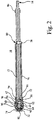
- Fig. 1 shows an exploded view of a reamer driver 10 in accordance with the present invention.
- Reamer driver 10 has a central shaft 12 rotatable about a longitudinal axis A at an RPM that is appropriate for removal of material during a surgical procedure.
- Shaft 12 has a proximal end 14 with an interface having an appropriate to receive a power element to produce the correct torque and RPM to perform the surgical removal of material.
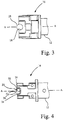
- Central shaft 12 has a distal end 16 for receiving one of a plurality of different styles of surgical reamers. As shown particularly in Figs. 3 and 4 , distal end 16 has a plurality of recesses integrally formed with the end of shaft 12. It should be apparent, however, to those skilled in the art that the recesses may be formed in a separate element that is affixed to the end of shaft 12. A pair of recesses 18 are semicircular in cross section as shown in Fig. 3 . Recesses 18 are formed in portions of the distal end 16 offset from the central axis A and permit movement directly in an axial direction as shown in Fig. 3. Figure 4 shows a pair of recesses 20 including a base 22 and a shoulder 24 connecting to sidewalls 26. Recesses 20 are positioned at 90 degrees relative to recesses 18.
- the crossbar interface is illustrated by dashed lines 28, shown in Fig 3 and Figure 4 .
- the other surgical reamer is an Othy cross bridge reamer having a circular center and two radially extending bars illustrated by dashed line 30.
- the crossbridge reamer 30 rests on the shoulder 24.
- the cross bridge reamer is also moveable into and out of the recesses 20 in an axial direction as illustrated in Fig. 4 .
- Grips 32-34 comprise base elements 36 and 37 having a central aligned holes 40 to provide a pivotal mounting on central shaft 12.
- Bases 36 extend to integral gripping elements 38 having an L-shaped extension 41 so that the grips 32-34 form an L-shape with a pivotal mounting at one end of the L.
- the extension 41 has a gripping surface 42 with a contour that provides a negative angle with respect to the center of bore 40 so as to accommodate varying thicknesses of reamers.
- the surface 44 has approximately a 4 degree angle with respect to a plane at right angles to a line extending through bore 40.
- An intermediate section 46 has a camming surface 48 projecting downward as shown in Figs. 5 and 6 to interact with elements of the reamer driver 10 disclosed below.
- the grips 32 and 34 are pivotally connected to shaft 12 at surfaces 50 with a through hole 52 by a pin 54 extending through bore 40 and through hole 52.
- the grips 32 and 34 are mounted so as to grip or release the respective reamers 28 and 30 in an axial direction.
- Fig. 2 shows the grips 32 and 34 in the retention position.
- Grips 32 and 34 are biased to the open position permitting removal of the reamers 28 or 30. As shown in Figs 1 and 2 , this is done by a central plunger 56 received in an axial bore 58 of central shaft 12. Plunger 56 is retained within the bore 58 by a removable ring 60 and is biases towards the left by a spring 62 retained within bore 58. Plunger 56 has a shoulder 64 that acts as a camming surface for the corresponding camming surface 48 on grips 32-34 so as to displace them in a radially outward direction upon axial movement of plunger 56 towards the distal end of shaft 12. Thus, in the absence of any restraining element, the grips 32 and 34 are urged to their open position.
- the grips 32-34 are urged to the closed position illustrated in Fig. 2 by a sleeve 66 telescoped over shaft 12.
- Sleeve 66 has an inwardly facing shoulder 68 which abuts a corresponding outwardly facing shoulder 70 on shaft 12 to limit the left most position of sleeve 66.
- Sleeve 66 has a suitable serrated gripping surface 67 to enable manual manipulation.
- Sleeve 66 is urged to the leftmost position by a spring 74 retained over shaft 12 and abutting a protective sleeve 76, also telescoped over shaft 12.
- Projective sleeve 76 is retained on shaft 12 by a pin 78 received in a cross bore 80 of shaft 12 and yieldably urged to the position shown in Fig. 2 by a spring 82.
- An appropriate cap 84 retains spring 82 within the bore 80.
- a retention sleeve 86 is appropriately affixed to the proximal end 14 of shaft 12 so as to limit the rightmost movement of protective sleeve 76.
- radial passages 88 are provided from recess 58 to the exterior and a central passage 90 is provided in plunger 56.
- plunger 56 has cross semicircular recesses 92 at 90 degrees to one another to abut the crossbars of reamer style 28 so as to further stabilize it.
- the reamer driver 10 is operated by pulling sleeve 66 to the right as viewed in Fig. 2 so as to free the grips 32 and 34 and permit the spring 62 to displace the plunger 56 axially so that shoulder 64 urges the camming surface 48 radially outward.
- the arc of movement is sufficient to permit the surfaces 42 of grips 32-34 to provide axial clearance permitting removal or installation of the reamer driver styles 28 and 30 in an axial direction only. While the sleeve 66 is retracted, either reamer driver style 28 or 30 is axially inserted into the appropriate recesses and the plunger 56 is displaced to the right as shown in Fig. 2 .
- the semicircular recesses 92 embrace the crossbars so as to stabilize the reamer.
- the end of plunger 56 abuts the undersurface of the crossbridge reamer 30.
- the displacement of the plunger 56 to the right permits the grips 32 and 34 to be acted on by sleeve 66 as urged by spring 74. This action holds the drivers in place for a surgical procedure.
- the sleeve 66 is simply displaced axially to the right as shown in Fig. 2 and the plunger 56 automatically urges either driver style from the driver assembly, thus eliminating multiple movements during a surgical procedure.
- the displacement of pin 78 permits the protective sleeve 76 to be moved to the right against retention sleeve 86, thus allowing total expansion of the grips 32 and 34 for cleaning.
- the radial passages provided in plunger 66 and in the sidewall of recess 58 also facilitate the cleaning of the assembly.
- the angle provided on surface 44 of grip 32-34 enables the retention of a range of thicknesses for the reamers 28 and 30.
Description
- The present invention relates to orthopedic surgical reamers and more specifically to drivers for such tools.
- In the field of orthopaedic surgery, it is often necessary to remove bone material to enable implantation of prosthesis to repair joints in the human body. Patella cutters and acetabular reamer cups and glenoid reamers are surgical tools which are used in surgery for the insertion of artificial joints. Acetabular reamer cups are used to cut hemispherical cavities in pelvis bones for the insertion of artificial hip joints. Patella cutters are used to shape the underside of the patella or knee cap during knee replacement surgery. Glenoid reamers are used to cut hemispherical cavities in shoulder bones for the insertion of artificial shoulder joints. Patella cutters have a complex arrangement of precisely shaped cutting edges arranged around an axis of rotation for cutting the patella. Acetabular reamer cups and glenoid reamers have a complex arrangement of cutting edges arranged on a spherical surface around the axis of rotation of the cup.
- A number of tools have been developed for this purpose and include reamers having generally semi-hemispherical configuration with cutting elements on them so that a corresponding semi-hemispherical hollow can be formed in the bone material for providing a foundation for the repair of the joint.
- There are two major driver styles in the field, one of which is for the Othy style manufactured by Symmetry Medical, Inc. and the other style manufactured by Precimed SA of L'Echelette, Switzerland. Although these both have semi-hemispherical cutting heads, they have different interfaces between driving tools with which they are associated. The Othy style has a crossbridge element. This element is a bar extending between the circumference of the hemisphere and having a circular expanded section in the middle. Numerous arrangements are available for securing this device as exemplified by
U.S. Patent 6,854,742 . Alternatively, the Precimed reamer has a crossbar shape in which two circular cross section bars intersect at the center and extend to the walls of the hemisphere. An example of a driver for this type is found inUS patent 5,658,290 in which a bayonet interconnection is provided between the reamer and the driver. - Typically, surgeons use specialized drivers for each of the reamers. The drivers connect to a source of power and have appropriate handles for guiding the operation of the reamer by a surgeon. If a surgeon has one of the adaptors, it is difficult to utilize the other type of reamer since it requires a specialized driver for that reamer. It has been proposed in
U.S. Patent 7,115,119 to provide a dual adapter that accommodates both the Othy and the Precimed reamers. However, this style of dual reamer requires a bayonet interconnection in which the assemblies are inserted axially and then a rotational movement, in accordance with a bayonet connection, is provided to lock the elements in place. This type of action slows the process of utilizing a new reamer because of the additional movement, But, more than that, the release of the device, after it has been in the surgical environment, is more difficult because it requires holding the reamer to reverse the rotational movement and then axial movement to finally free the reamer.
FromUS 2007/191854 A1 a tool holder releasably coupling a surgical tool such as a reaming tool to a drive shaft which tool has radially extending mounting elements has been made known. The holder includes a head portion coupled to an end of the drive shaft, the head portion having a body with an outwardly open groove extending thereacross for receiving
the radially extending mounting elements on the tool. The head portion includes a bore extending through the body in communication with the groove. A biased lock pin is slidably mounted in the bore of the head portion and is biased into a position whereby the locked pin engages the rod and locks it in place. A spring-biased lock collar is provided having stop surfaces thereon for engaging tow stop surfaces on the lock pin a frist locking the lock pin in the locked position and a second maintaining the lock pin in the open position. -
EP 1 074 225 shows a tool driver having a shaft with a longitudinal axis and opposite ends and tools therefore. A boss is secured at one of said shaft ends by which the toll driver may be driven by a surgical hand piece having a chuck in which the collet may be positioned. The boss has a surface which engages the tool and positions the tool exactly coaxially ot the tool driver. A latch mechanism is provide to hold the rotary tool on the boss, whereby the rotary tool is held exactly coaxially of the tool driver. The rotary tool which is used with the driver has a bottom tool driver opening which has the same dimensions as the boss of the tool driver of the invention. The boss thus fills the opening and the opening is complementary to the boss. The boss of the tool driver and the bottom tool driver opening of the tool are both positioned precisely coaxial of the axis of the tool and longitudinal axis of the tool driver about which the cutting edges are precisely positioned and rotated. - What is needed in the art, therefore, is a tool driver for surgical reamers that enables rapid and immediate connection and disconnection of the reamers.
- The problem of the invention is solved by a tool driver according to claim 1. The invention provide for a tool driver for multiple styles of surgical reamers. The driver includes a central shaft rotatable about a longitudinal axis and having a proximal driven end and a distal end. A reamer receiver is carried by the distal end of the shaft and the receiver has axially facing sets of recesses for receiving at least two different styles of surgical reamers. A gripping device is provided for releasably holding the surgical reamer assemblies in place, the releasable holding device permitting axial removal of the different styles of surgical reamers.
- The above-mentioned and other features and advantages of this invention, and the manner of attaining them, will become more apparent and the invention will be better understood by reference to the following description of an embodiment of the invention taken in conjunction with the accompanying drawings, wherein:
-
Fig. 1 is an exploded perspective view of a tool driver in accordance with the present invention; -
Fig. 2 is a longitudinal section view of the tool driver shown inFig. 1 ; -
Fig. 3 is an expanded detailed view of a portion of the tool driver inFig. 1 and2 taken in the same plane asFig. 2 ; -
Fig. 4 is an enlarged detailed view of a portion of the tool driver shown inFig. 2 taken on a plane at 90 degrees to the plane ofFig. 2 ; -
Fig. 5 is a side view of an element of the tool driver shown inFigs. 1-4 ; and -
Fig. 6 is a top view of the element shown inFig. 5 . - Corresponding reference characters indicate corresponding parts throughout the several views. The exemplification set out herein illustrates one embodiment of the invention and such exemplifications are not to be construed as limiting the scope of the invention in any manner.
-
Fig. 1 shows an exploded view of areamer driver 10 in accordance with the present invention.Reamer driver 10 has acentral shaft 12 rotatable about a longitudinal axis A at an RPM that is appropriate for removal of material during a surgical procedure. Shaft 12 has aproximal end 14 with an interface having an appropriate to receive a power element to produce the correct torque and RPM to perform the surgical removal of material. -
Central shaft 12 has adistal end 16 for receiving one of a plurality of different styles of surgical reamers. As shown particularly inFigs. 3 and 4 ,distal end 16 has a plurality of recesses integrally formed with the end ofshaft 12. It should be apparent, however, to those skilled in the art that the recesses may be formed in a separate element that is affixed to the end ofshaft 12. A pair ofrecesses 18 are semicircular in cross section as shown inFig. 3 .Recesses 18 are formed in portions of thedistal end 16 offset from the central axis A and permit movement directly in an axial direction as shown inFig. 3. Figure 4 shows a pair ofrecesses 20 including abase 22 and ashoulder 24 connecting tosidewalls 26.Recesses 20 are positioned at 90 degrees relative torecesses 18. - As stated previously there are two major styles of reamers in the surgical field, one of which is a crossbar and the other of which is a cross bridge. The crossbar interface is illustrated by dashed
lines 28, shown inFig 3 and Figure 4 . It is to be noted that the base ofsemicircular recess 18 andrecess base 22 are in the same plane so that the interface for thecrossbar reamer 28 is positioned in a common plane to stabilize it, The other surgical reamer is an Othy cross bridge reamer having a circular center and two radially extending bars illustrated by dashedline 30. Thecrossbridge reamer 30 rests on theshoulder 24. The cross bridge reamer is also moveable into and out of therecesses 20 in an axial direction as illustrated inFig. 4 . - The different styles of
reamers recesses grips Figs, 2 and3 and in detail inFigs. 5 and 6 . Thegrips Figs. 5 and 6 are applicable for both grips. Grips 32-34comprise base elements holes 40 to provide a pivotal mounting oncentral shaft 12.Bases 36 extend to integralgripping elements 38 having an L-shapedextension 41 so that the grips 32-34 form an L-shape with a pivotal mounting at one end of the L. Theextension 41 has agripping surface 42 with a contour that provides a negative angle with respect to the center ofbore 40 so as to accommodate varying thicknesses of reamers. Generally speaking thesurface 44 has approximately a 4 degree angle with respect to a plane at right angles to a line extending throughbore 40. Anintermediate section 46 has acamming surface 48 projecting downward as shown inFigs. 5 and 6 to interact with elements of thereamer driver 10 disclosed below. - The
grips shaft 12 atsurfaces 50 with a throughhole 52 by apin 54 extending throughbore 40 and throughhole 52. Thus, thegrips respective reamers Fig. 2 shows thegrips -
Grips reamers Figs 1 and2 , this is done by acentral plunger 56 received in anaxial bore 58 ofcentral shaft 12.Plunger 56 is retained within thebore 58 by a removable ring 60 and is biases towards the left by aspring 62 retained withinbore 58.Plunger 56 has ashoulder 64 that acts as a camming surface for thecorresponding camming surface 48 on grips 32-34 so as to displace them in a radially outward direction upon axial movement ofplunger 56 towards the distal end ofshaft 12. Thus, in the absence of any restraining element, thegrips - The grips 32-34 are urged to the closed position illustrated in
Fig. 2 by asleeve 66 telescoped overshaft 12.Sleeve 66 has an inwardly facingshoulder 68 which abuts a corresponding outwardly facingshoulder 70 onshaft 12 to limit the left most position ofsleeve 66.Sleeve 66 has a suitable serratedgripping surface 67 to enable manual manipulation.Sleeve 66 is urged to the leftmost position by aspring 74 retained overshaft 12 and abutting aprotective sleeve 76, also telescoped overshaft 12. -
Projective sleeve 76 is retained onshaft 12 by apin 78 received in across bore 80 ofshaft 12 and yieldably urged to the position shown inFig. 2 by aspring 82. Anappropriate cap 84 retainsspring 82 within thebore 80. Aretention sleeve 86 is appropriately affixed to theproximal end 14 ofshaft 12 so as to limit the rightmost movement ofprotective sleeve 76. - In order to facilitate cleaning of the reamer driver,
radial passages 88 are provided fromrecess 58 to the exterior and acentral passage 90 is provided inplunger 56. In addition,plunger 56 has crosssemicircular recesses 92 at 90 degrees to one another to abut the crossbars ofreamer style 28 so as to further stabilize it. - The
reamer driver 10 is operated by pullingsleeve 66 to the right as viewed inFig. 2 so as to free thegrips spring 62 to displace theplunger 56 axially so thatshoulder 64 urges thecamming surface 48 radially outward. The arc of movement is sufficient to permit thesurfaces 42 of grips 32-34 to provide axial clearance permitting removal or installation of thereamer driver styles sleeve 66 is retracted, eitherreamer driver style plunger 56 is displaced to the right as shown inFig. 2 . In the case ofreamer style 28, thesemicircular recesses 92 embrace the crossbars so as to stabilize the reamer. In the case ofreamer style 30, the end ofplunger 56 abuts the undersurface of thecrossbridge reamer 30. The displacement of theplunger 56 to the right permits thegrips sleeve 66 as urged byspring 74. This action holds the drivers in place for a surgical procedure. When the surgical procedure is completed, thesleeve 66 is simply displaced axially to the right as shown inFig. 2 and theplunger 56 automatically urges either driver style from the driver assembly, thus eliminating multiple movements during a surgical procedure. - In addition to providing a simplified axial movement for connection and removal, the displacement of
pin 78 permits theprotective sleeve 76 to be moved to the right againstretention sleeve 86, thus allowing total expansion of thegrips plunger 66 and in the sidewall ofrecess 58 also facilitate the cleaning of the assembly. - The angle provided on
surface 44 of grip 32-34 enables the retention of a range of thicknesses for thereamers - While this invention has been described with respect to at least one embodiment, the present invention can be further modified within the scope of the appended claims.
Claims (15)
- A tool driver for multiple styles of surgical reamers, said driver comprising:a central shaft (12) rotatable about a longitudinal axis and having a proximal driver end and a distal end (16);a reamer receiver carried by the distal end (16) of said shaft (12), said reamer receiver having axially facing sets of recesses (18) configured to receive at least two different styles of surgical reamers (28, 30);a L-shaped gripping device for releasably holding said surgical reamer assemblies in place, said gripping device being pivotally mounted on said shaft (12) and pivotal between a retention position and an open position permitting direct axial removal and installation of the different styles of surgical reamers (28, 30);said tool driver being characterized in that the distal end (16) of said shaft (12) has an axial bore (58) and a plunger (56) is received in said axial bore end, said plunger (56) interacting with said gripping device to urge said gripping device from said retention position to said open position upon axial movement of said plunger (56) in said bore (58); and in that it further comprises a first spring (62) for yieldably urging said plunger in an axial direction relative to said shaft (12) and urging said gripping device to said open position so that when said gripping device releases said at least two different styles of reamers (28, 30), they are automatically released from said in an axial direction;a sleeve (66) telescoped over said central shaft central shaft (12) and displaceable to hold said gripping device in said retention position; and a second spring (74) urging said sleeve (66) in the direction in which it holds said gripping device in said retention position.
- The tool driver as claimed in claim 1 wherein said gripping device has an L-shaped configuration with at least one leg capturing the style of reamer and retaining it in place in said recesses.
- The tool driver as claimed in claim 1 wherein said spring (74) is a coil spring to urge said sleeve (66) in the position to hold said gripping device in said retention position.
- The tool driver as claimed in claim 1 or 2 where in said plunger (56) has a camming surface (48) for interacting with, and urging said gripping device outward.
- The tool driver as claimed in claim 4 wherein said gripping device has at least one camming surface (48) on the inward facing side of the gripping device to interact with the camming surface (64) on said plunger (56).
- The tool driver as claimed in claim 5 having at least one pair of L-shaped elements pivotally mounted on adjacent opposite sides of the distal end (16) of said shaft (12) and having a central camming surface (48) in between the pairs.
- The tool driver as claimed in claim 6 having a pair of opposing L-shaped gripping devices each pivotally mounted on opposite sides of the distal end (16) of said shaft (12).
- The tool driver as claimed in claim 7 wherein said L-shaped elements have a first section pivotally mounted to said central shaft (12) and a second free end for gripping said surgical reamers (28, 30), the second section having a reverse angle to accommodate reamers of varying thickness.
- The tool driver as claimed in any one of the previous claims adapted to receive two different styles of reamers (28, 30), one of which has a crossbridge mounting interface and the other having a crossbar shape for said interface and further wherein the recesses in the distal end of said central shaft have a first set of recesses configured to receive the crossbridge element and a second set of recesses configured to receive both the crossbridge and crossbar elements.
- The tool driver as claimed in claim 9 wherein said gripping devices are L-shaped with one leg pivotally mounted on said distal end of said central shaft and said elements are pivotal to retain the crossbridge of said crossbridge style reamer and one of the sets of bars of the crossbar reamer.
- The tool driver as claimed in claim 9 wherein said plunger has cross recesses for abutting, holding and stabilizing said crossbar style reamer.
- The tool driver as claimed in any one of the previous claims wherein said central shaft has at least one passage extending from the axial bore adjacent the distal end to the exterior for enhancing cleaning of the tool driver.
- The tool driver as claimed in any one of the previous claims wherein said sleeve is removably telescoped over the exterior of said central shaft.
- The tool driver as claimed in claim 13 further comprising a radially extending pin yieldably urged radially outward on said shaft remote from said distal end for providing an abutment for said telescoped sleeve, said pin being urgeable inward to release said telescoped sleeve to provide access for cleaning.
- The tool driver as claimed in claim 14 further comprising a stop ring secured to said central shaft adjacent its proximal end for permanently holding said sleeve on said shaft.
Applications Claiming Priority (3)
| Application Number | Priority Date | Filing Date | Title |
|---|---|---|---|
| US97391907P | 2007-09-20 | 2007-09-20 | |
| US12/233,149 US8398642B2 (en) | 2007-09-20 | 2008-09-18 | Dual reamer driver |
| PCT/US2008/076971 WO2009039346A1 (en) | 2007-09-20 | 2008-09-19 | Dual reamer driver |
Publications (3)
| Publication Number | Publication Date |
|---|---|
| EP2192862A1 EP2192862A1 (en) | 2010-06-09 |
| EP2192862A4 EP2192862A4 (en) | 2014-05-07 |
| EP2192862B1 true EP2192862B1 (en) | 2017-06-14 |
Family
ID=40468364
Family Applications (1)
| Application Number | Title | Priority Date | Filing Date |
|---|---|---|---|
| EP08831415.8A Active EP2192862B1 (en) | 2007-09-20 | 2008-09-19 | Dual reamer driver |
Country Status (3)
| Country | Link |
|---|---|
| US (2) | US8398642B2 (en) |
| EP (1) | EP2192862B1 (en) |
| WO (1) | WO2009039346A1 (en) |
Families Citing this family (15)
| Publication number | Priority date | Publication date | Assignee | Title |
|---|---|---|---|---|
| EP1979079A4 (en) | 2006-02-03 | 2012-11-28 | Integenx Inc | Microfluidic devices |
| DE102010056307A1 (en) * | 2010-07-26 | 2012-01-26 | Adeor Medical Technologies Gmbh | Multisystem drilling and milling insert |
| EP2606154B1 (en) | 2010-08-20 | 2019-09-25 | Integenx Inc. | Integrated analysis system |
| US20150136604A1 (en) | 2011-10-21 | 2015-05-21 | Integenx Inc. | Sample preparation, processing and analysis systems |
| US10865440B2 (en) | 2011-10-21 | 2020-12-15 | IntegenX, Inc. | Sample preparation, processing and analysis systems |
| CN110560187B (en) | 2013-11-18 | 2022-01-11 | 尹特根埃克斯有限公司 | Cartridge and instrument for sample analysis |
| WO2015179098A1 (en) | 2014-05-21 | 2015-11-26 | Integenx Inc. | Fluidic cartridge with valve mechanism |
| EP3552690A1 (en) | 2014-10-22 | 2019-10-16 | IntegenX Inc. | Systems and methods for sample preparation, processing and analysis |
| US10092301B2 (en) | 2014-11-19 | 2018-10-09 | Symmetry Medical Manufacturing, Inc. | Orthopaedic reamer connector |
| US9924955B2 (en) | 2014-11-19 | 2018-03-27 | Symmetry Medical Manufacturing, Inc. | Orthopaedic reamer connector |
| BR112018003064B1 (en) | 2015-08-18 | 2023-03-14 | Incipio Devices Sa | SURGICAL MANDREL ACTUATOR AND SURGICAL KIT |
| US10687852B2 (en) | 2015-09-14 | 2020-06-23 | Symmetry Medical Manufacturing, Inc. | Separable instrument driver handle |
| US10660658B2 (en) | 2015-11-18 | 2020-05-26 | Incipio Devices Sa | Reamer driver connection |
| WO2018033788A1 (en) | 2016-08-18 | 2018-02-22 | Incipio Devices Sa | Offset reamer driver |
| GB201906313D0 (en) * | 2019-05-03 | 2019-06-19 | Depuy Ireland Ultd Co | Surgical rotational tool driver and method |
Family Cites Families (21)
| Publication number | Priority date | Publication date | Assignee | Title |
|---|---|---|---|---|
| US3702611A (en) | 1971-06-23 | 1972-11-14 | Meyer Fishbein | Surgical expansive reamer for hip socket |
| CA1031945A (en) * | 1974-08-06 | 1978-05-30 | Bernhard Bellmann | Milling cutter for preparing socket joints in complete prosthetic hip joint replacements |
| US4834092A (en) | 1986-04-03 | 1989-05-30 | Minnesota Mining And Manufacturing Company | Device for driving tools used in orthopedic surgery |
| US5062749A (en) * | 1989-02-21 | 1991-11-05 | Sheets Harold D | Tool coupler |
| US5171313A (en) * | 1991-05-08 | 1992-12-15 | Othy, Inc. | Tool driver |
| US5553675A (en) | 1994-06-10 | 1996-09-10 | Minnesota Mining And Manufacturing Company | Orthopedic surgical device |
| CH690021A5 (en) | 1994-09-28 | 2000-03-31 | Precifar Sa | Cutter holder and cutter set for surgery. |
| US5817096A (en) | 1996-11-25 | 1998-10-06 | Othy, Inc. | Tool driver |
| DE19707373C1 (en) | 1997-02-25 | 1998-02-05 | Storz Karl Gmbh & Co | Releasable connection of two tube shaft instruments or instrument parts |
| US5980170A (en) * | 1998-03-27 | 1999-11-09 | Othy, Inc. | Tool driver |
| US6250858B1 (en) * | 1998-03-27 | 2001-06-26 | Othy, Inc. | Tool driver and tools therefor |
| DE19836950B4 (en) | 1998-08-17 | 2004-09-02 | Deutsches Zentrum für Luft- und Raumfahrt e.V. | Surgical instrument in the form of a suturing device |
| US6409732B1 (en) | 1999-07-09 | 2002-06-25 | Othy, Inc. | Tool driver |
| US7326198B2 (en) | 2000-06-24 | 2008-02-05 | Precimed S.A. | Remote release instrument holder for surgical use |
| US7229078B2 (en) | 2000-06-24 | 2007-06-12 | Precimed S.A. | Hollow small diameter tool holder for surgical use |
| US7115119B2 (en) * | 2000-06-24 | 2006-10-03 | Precimed S.A. | Dual reamer holder for surgical use |
| US6283972B1 (en) | 2000-10-25 | 2001-09-04 | Riley Medical, Inc. | Holder for acetabular reamer |
| CN1230129C (en) * | 2001-02-10 | 2005-12-07 | 普雷西梅德公司 | Modular tool connection assembly |
| US6875217B2 (en) | 2003-01-08 | 2005-04-05 | Symmetry Medical, Inc. | Orthopaedic reamer assembly |
| DE202005016761U1 (en) | 2005-10-26 | 2006-11-30 | Joimax Gmbh | Surgical milling cutter in particular for removal of tissue from facet joint at spine, comprises handle to be attached with quick joining mechanism |
| US7513899B2 (en) * | 2006-01-27 | 2009-04-07 | Howmedica Osteonics Corp. | Acetabular reamer connection mechanism |
-
2008
- 2008-09-18 US US12/233,149 patent/US8398642B2/en active Active
- 2008-09-19 WO PCT/US2008/076971 patent/WO2009039346A1/en active Application Filing
- 2008-09-19 EP EP08831415.8A patent/EP2192862B1/en active Active
-
2013
- 2013-03-18 US US13/846,116 patent/US9198672B2/en active Active
Non-Patent Citations (1)
| Title |
|---|
| None * |
Also Published As
| Publication number | Publication date |
|---|---|
| EP2192862A1 (en) | 2010-06-09 |
| US20130213678A1 (en) | 2013-08-22 |
| US20090082771A1 (en) | 2009-03-26 |
| US8398642B2 (en) | 2013-03-19 |
| WO2009039346A1 (en) | 2009-03-26 |
| EP2192862A4 (en) | 2014-05-07 |
| US9198672B2 (en) | 2015-12-01 |
Similar Documents
| Publication | Publication Date | Title |
|---|---|---|
| EP2192862B1 (en) | Dual reamer driver | |
| JP7439218B2 (en) | Systems and methods for inverted shoulder implants | |
| JP5148516B2 (en) | Femur reaming system and method for reducing the number of trials | |
| US7993348B2 (en) | Curved acetabular positioner, impactor and reamer handle | |
| US7503921B2 (en) | Variable angle orthopaedic reamer driver | |
| CN106974699B (en) | The device assembly of implantation amendment hip prosthesis | |
| US7513899B2 (en) | Acetabular reamer connection mechanism | |
| US8323284B2 (en) | Adapter driver for orthopaedic reamer | |
| US5499985A (en) | Detachable coupling system for surgical instruments | |
| EP2120735B1 (en) | Surgical tool holder and surgical tool | |
| RU2693349C1 (en) | Surgical cutting instruments | |
| US7955323B2 (en) | Instrument holder and method for a surgical instrument having a park position | |
| US20070167952A1 (en) | Surgical tool holder for facilitated sterilization | |
| US8177788B2 (en) | In-line milling system | |
| US10568649B2 (en) | Acetabular reamer | |
| JP7022433B2 (en) | Surgical trays, instruments, and methods for implanting hip replacements | |
| KR102650025B1 (en) | Drill guide for acetabular cup fasteners | |
| US10631880B1 (en) | Cannulated modular magnetic glenoid reamer | |
| US11123086B1 (en) | Cannulated modular magnetic glenoid reamer | |
| EP1905362A1 (en) | Precision assembleable surgical tool handle with limited-play interconnect mechanism |
Legal Events
| Date | Code | Title | Description |
|---|---|---|---|
| PUAI | Public reference made under article 153(3) epc to a published international application that has entered the european phase |
Free format text: ORIGINAL CODE: 0009012 |
|
| 17P | Request for examination filed |
Effective date: 20100319 |
|
| AK | Designated contracting states |
Kind code of ref document: A1 Designated state(s): AT BE BG CH CY CZ DE DK EE ES FI FR GB GR HR HU IE IS IT LI LT LU LV MC MT NL NO PL PT RO SE SI SK TR |
|
| AX | Request for extension of the european patent |
Extension state: AL BA MK RS |
|
| DAX | Request for extension of the european patent (deleted) | ||
| A4 | Supplementary search report drawn up and despatched |
Effective date: 20140408 |
|
| RIC1 | Information provided on ipc code assigned before grant |
Ipc: A61B 17/16 20060101AFI20140402BHEP |
|
| 17Q | First examination report despatched |
Effective date: 20160627 |
|
| GRAP | Despatch of communication of intention to grant a patent |
Free format text: ORIGINAL CODE: EPIDOSNIGR1 |
|
| RIC1 | Information provided on ipc code assigned before grant |
Ipc: A61B 17/16 20060101AFI20170222BHEP Ipc: B23B 31/18 20060101ALI20170222BHEP |
|
| INTG | Intention to grant announced |
Effective date: 20170313 |
|
| GRAS | Grant fee paid |
Free format text: ORIGINAL CODE: EPIDOSNIGR3 |
|
| GRAA | (expected) grant |
Free format text: ORIGINAL CODE: 0009210 |
|
| AK | Designated contracting states |
Kind code of ref document: B1 Designated state(s): AT BE BG CH CY CZ DE DK EE ES FI FR GB GR HR HU IE IS IT LI LT LU LV MC MT NL NO PL PT RO SE SI SK TR |
|
| REG | Reference to a national code |
Ref country code: GB Ref legal event code: FG4D |
|
| REG | Reference to a national code |
Ref country code: CH Ref legal event code: EP Ref country code: AT Ref legal event code: REF Ref document number: 900239 Country of ref document: AT Kind code of ref document: T Effective date: 20170615 |
|
| REG | Reference to a national code |
Ref country code: IE Ref legal event code: FG4D |
|
| REG | Reference to a national code |
Ref country code: DE Ref legal event code: R082 Ref document number: 602008050692 Country of ref document: DE Representative=s name: SAWODNY - HOEFER PATENTANWAELTE PARTNERSCHAFTS, DE Ref country code: DE Ref legal event code: R081 Ref document number: 602008050692 Country of ref document: DE Owner name: SYMMETRY MEDICAL MANUFACTURING, INC., WARSAW, US Free format text: FORMER OWNER: SYMMETRY MEDICAL, INC., WARSAW, IND., US |
|
| REG | Reference to a national code |
Ref country code: DE Ref legal event code: R096 Ref document number: 602008050692 Country of ref document: DE |
|
| REG | Reference to a national code |
Ref country code: CH Ref legal event code: NV Representative=s name: ISLER AND PEDRAZZINI AG, CH |
|
| REG | Reference to a national code |
Ref country code: FR Ref legal event code: PLFP Year of fee payment: 10 |
|
| REG | Reference to a national code |
Ref country code: GB Ref legal event code: 732E Free format text: REGISTERED BETWEEN 20170907 AND 20170913 |
|
| REG | Reference to a national code |
Ref country code: NL Ref legal event code: MP Effective date: 20170614 |
|
| REG | Reference to a national code |
Ref country code: LT Ref legal event code: MG4D |
|
| PG25 | Lapsed in a contracting state [announced via postgrant information from national office to epo] |
Ref country code: NO Free format text: LAPSE BECAUSE OF FAILURE TO SUBMIT A TRANSLATION OF THE DESCRIPTION OR TO PAY THE FEE WITHIN THE PRESCRIBED TIME-LIMIT Effective date: 20170914 Ref country code: LT Free format text: LAPSE BECAUSE OF FAILURE TO SUBMIT A TRANSLATION OF THE DESCRIPTION OR TO PAY THE FEE WITHIN THE PRESCRIBED TIME-LIMIT Effective date: 20170614 Ref country code: HR Free format text: LAPSE BECAUSE OF FAILURE TO SUBMIT A TRANSLATION OF THE DESCRIPTION OR TO PAY THE FEE WITHIN THE PRESCRIBED TIME-LIMIT Effective date: 20170614 Ref country code: FI Free format text: LAPSE BECAUSE OF FAILURE TO SUBMIT A TRANSLATION OF THE DESCRIPTION OR TO PAY THE FEE WITHIN THE PRESCRIBED TIME-LIMIT Effective date: 20170614 Ref country code: ES Free format text: LAPSE BECAUSE OF FAILURE TO SUBMIT A TRANSLATION OF THE DESCRIPTION OR TO PAY THE FEE WITHIN THE PRESCRIBED TIME-LIMIT Effective date: 20170614 Ref country code: GR Free format text: LAPSE BECAUSE OF FAILURE TO SUBMIT A TRANSLATION OF THE DESCRIPTION OR TO PAY THE FEE WITHIN THE PRESCRIBED TIME-LIMIT Effective date: 20170915 |
|
| REG | Reference to a national code |
Ref country code: AT Ref legal event code: MK05 Ref document number: 900239 Country of ref document: AT Kind code of ref document: T Effective date: 20170614 |
|
| PG25 | Lapsed in a contracting state [announced via postgrant information from national office to epo] |
Ref country code: LV Free format text: LAPSE BECAUSE OF FAILURE TO SUBMIT A TRANSLATION OF THE DESCRIPTION OR TO PAY THE FEE WITHIN THE PRESCRIBED TIME-LIMIT Effective date: 20170614 Ref country code: NL Free format text: LAPSE BECAUSE OF FAILURE TO SUBMIT A TRANSLATION OF THE DESCRIPTION OR TO PAY THE FEE WITHIN THE PRESCRIBED TIME-LIMIT Effective date: 20170614 Ref country code: BG Free format text: LAPSE BECAUSE OF FAILURE TO SUBMIT A TRANSLATION OF THE DESCRIPTION OR TO PAY THE FEE WITHIN THE PRESCRIBED TIME-LIMIT Effective date: 20170914 Ref country code: SE Free format text: LAPSE BECAUSE OF FAILURE TO SUBMIT A TRANSLATION OF THE DESCRIPTION OR TO PAY THE FEE WITHIN THE PRESCRIBED TIME-LIMIT Effective date: 20170614 |
|
| REG | Reference to a national code |
Ref country code: CH Ref legal event code: PUE Owner name: SYMMETRY MEDICAL MANUFACTURING, INC., US Free format text: FORMER OWNER: SYMMETRY MEDICAL, INC., US |
|
| PG25 | Lapsed in a contracting state [announced via postgrant information from national office to epo] |
Ref country code: RO Free format text: LAPSE BECAUSE OF FAILURE TO SUBMIT A TRANSLATION OF THE DESCRIPTION OR TO PAY THE FEE WITHIN THE PRESCRIBED TIME-LIMIT Effective date: 20170614 Ref country code: AT Free format text: LAPSE BECAUSE OF FAILURE TO SUBMIT A TRANSLATION OF THE DESCRIPTION OR TO PAY THE FEE WITHIN THE PRESCRIBED TIME-LIMIT Effective date: 20170614 Ref country code: EE Free format text: LAPSE BECAUSE OF FAILURE TO SUBMIT A TRANSLATION OF THE DESCRIPTION OR TO PAY THE FEE WITHIN THE PRESCRIBED TIME-LIMIT Effective date: 20170614 Ref country code: CZ Free format text: LAPSE BECAUSE OF FAILURE TO SUBMIT A TRANSLATION OF THE DESCRIPTION OR TO PAY THE FEE WITHIN THE PRESCRIBED TIME-LIMIT Effective date: 20170614 Ref country code: SK Free format text: LAPSE BECAUSE OF FAILURE TO SUBMIT A TRANSLATION OF THE DESCRIPTION OR TO PAY THE FEE WITHIN THE PRESCRIBED TIME-LIMIT Effective date: 20170614 |
|
| PG25 | Lapsed in a contracting state [announced via postgrant information from national office to epo] |
Ref country code: PL Free format text: LAPSE BECAUSE OF FAILURE TO SUBMIT A TRANSLATION OF THE DESCRIPTION OR TO PAY THE FEE WITHIN THE PRESCRIBED TIME-LIMIT Effective date: 20170614 Ref country code: IS Free format text: LAPSE BECAUSE OF FAILURE TO SUBMIT A TRANSLATION OF THE DESCRIPTION OR TO PAY THE FEE WITHIN THE PRESCRIBED TIME-LIMIT Effective date: 20171014 |
|
| REG | Reference to a national code |
Ref country code: DE Ref legal event code: R097 Ref document number: 602008050692 Country of ref document: DE |
|
| REG | Reference to a national code |
Ref country code: FR Ref legal event code: TP Owner name: SYMMETRY MEDICAL MANUFACTURING, INC., US Effective date: 20180219 |
|
| PLBE | No opposition filed within time limit |
Free format text: ORIGINAL CODE: 0009261 |
|
| STAA | Information on the status of an ep patent application or granted ep patent |
Free format text: STATUS: NO OPPOSITION FILED WITHIN TIME LIMIT |
|
| PG25 | Lapsed in a contracting state [announced via postgrant information from national office to epo] |
Ref country code: DK Free format text: LAPSE BECAUSE OF FAILURE TO SUBMIT A TRANSLATION OF THE DESCRIPTION OR TO PAY THE FEE WITHIN THE PRESCRIBED TIME-LIMIT Effective date: 20170614 |
|
| 26N | No opposition filed |
Effective date: 20180315 |
|
| PG25 | Lapsed in a contracting state [announced via postgrant information from national office to epo] |
Ref country code: MC Free format text: LAPSE BECAUSE OF FAILURE TO SUBMIT A TRANSLATION OF THE DESCRIPTION OR TO PAY THE FEE WITHIN THE PRESCRIBED TIME-LIMIT Effective date: 20170614 |
|
| REG | Reference to a national code |
Ref country code: IE Ref legal event code: MM4A |
|
| REG | Reference to a national code |
Ref country code: BE Ref legal event code: MM Effective date: 20170930 |
|
| PG25 | Lapsed in a contracting state [announced via postgrant information from national office to epo] |
Ref country code: LU Free format text: LAPSE BECAUSE OF NON-PAYMENT OF DUE FEES Effective date: 20170919 |
|
| PG25 | Lapsed in a contracting state [announced via postgrant information from national office to epo] |
Ref country code: IE Free format text: LAPSE BECAUSE OF NON-PAYMENT OF DUE FEES Effective date: 20170919 |
|
| PG25 | Lapsed in a contracting state [announced via postgrant information from national office to epo] |
Ref country code: SI Free format text: LAPSE BECAUSE OF FAILURE TO SUBMIT A TRANSLATION OF THE DESCRIPTION OR TO PAY THE FEE WITHIN THE PRESCRIBED TIME-LIMIT Effective date: 20170614 Ref country code: BE Free format text: LAPSE BECAUSE OF NON-PAYMENT OF DUE FEES Effective date: 20170930 |
|
| REG | Reference to a national code |
Ref country code: FR Ref legal event code: PLFP Year of fee payment: 11 |
|
| PG25 | Lapsed in a contracting state [announced via postgrant information from national office to epo] |
Ref country code: MT Free format text: LAPSE BECAUSE OF NON-PAYMENT OF DUE FEES Effective date: 20170919 |
|
| PG25 | Lapsed in a contracting state [announced via postgrant information from national office to epo] |
Ref country code: HU Free format text: LAPSE BECAUSE OF FAILURE TO SUBMIT A TRANSLATION OF THE DESCRIPTION OR TO PAY THE FEE WITHIN THE PRESCRIBED TIME-LIMIT; INVALID AB INITIO Effective date: 20080919 |
|
| PG25 | Lapsed in a contracting state [announced via postgrant information from national office to epo] |
Ref country code: CY Free format text: LAPSE BECAUSE OF NON-PAYMENT OF DUE FEES Effective date: 20170614 |
|
| PG25 | Lapsed in a contracting state [announced via postgrant information from national office to epo] |
Ref country code: TR Free format text: LAPSE BECAUSE OF FAILURE TO SUBMIT A TRANSLATION OF THE DESCRIPTION OR TO PAY THE FEE WITHIN THE PRESCRIBED TIME-LIMIT Effective date: 20170614 |
|
| PG25 | Lapsed in a contracting state [announced via postgrant information from national office to epo] |
Ref country code: PT Free format text: LAPSE BECAUSE OF FAILURE TO SUBMIT A TRANSLATION OF THE DESCRIPTION OR TO PAY THE FEE WITHIN THE PRESCRIBED TIME-LIMIT Effective date: 20170614 |
|
| PGFP | Annual fee paid to national office [announced via postgrant information from national office to epo] |
Ref country code: IT Payment date: 20230921 Year of fee payment: 16 Ref country code: GB Payment date: 20230927 Year of fee payment: 16 |
|
| PGFP | Annual fee paid to national office [announced via postgrant information from national office to epo] |
Ref country code: FR Payment date: 20230925 Year of fee payment: 16 Ref country code: DE Payment date: 20230927 Year of fee payment: 16 |
|
| PGFP | Annual fee paid to national office [announced via postgrant information from national office to epo] |
Ref country code: CH Payment date: 20231004 Year of fee payment: 16 |