EP2192789A2 - Earpiece and earphone - Google Patents
Earpiece and earphone Download PDFInfo
- Publication number
- EP2192789A2 EP2192789A2 EP09252613A EP09252613A EP2192789A2 EP 2192789 A2 EP2192789 A2 EP 2192789A2 EP 09252613 A EP09252613 A EP 09252613A EP 09252613 A EP09252613 A EP 09252613A EP 2192789 A2 EP2192789 A2 EP 2192789A2
- Authority
- EP
- European Patent Office
- Prior art keywords
- earpiece
- cap
- main unit
- end surface
- cap portion
- Prior art date
- Legal status (The legal status is an assumption and is not a legal conclusion. Google has not performed a legal analysis and makes no representation as to the accuracy of the status listed.)
- Withdrawn
Links
Images










Classifications
-
- H—ELECTRICITY
- H04—ELECTRIC COMMUNICATION TECHNIQUE
- H04R—LOUDSPEAKERS, MICROPHONES, GRAMOPHONE PICK-UPS OR LIKE ACOUSTIC ELECTROMECHANICAL TRANSDUCERS; ELECTRIC HEARING AIDS; PUBLIC ADDRESS SYSTEMS
- H04R1/00—Details of transducers, loudspeakers or microphones
- H04R1/10—Earpieces; Attachments therefor ; Earphones; Monophonic headphones
- H04R1/1016—Earpieces of the intra-aural type
Definitions
- the present invention relates to an earpiece and an earphone.
- the audio playback apparatuses output audio from earphones, for example, and thereby provide the sound to users.
- earphones various types are available and the taste of earphones often varies from user to user.
- numbers of earphones called earplug type (canal type)
- canal type are commercialized in which an earpiece is attached to a front end of a sound conduit.
- the size of an ear canal varies from user to user.
- the size of an earpiece is small, there is more sound leakage, degrading sound quality.
- earpieces of a plurality of sizes such as S, M, and L, are sold in a package according to the size of an ear, to support users with different sizes of ear canals.
- earpieces are developed that can be applied to people with different sizes of ears, with one earpiece without attaching a plurality of types of earpieces.
- each cap portion which abuts a user's ear is formed by a plurality of stages with different sizes, which enables to support the size of a user's ear canal.
- many users get an uncomfortable feeling in fit, e.g., stages that do not match the size of a user's ear canal press the user's ear canal, and thus earpieces with further improved fit are sought.
- an earpiece comprising: a main unit having a cylindrical shape having made therein a through hole that can allow sound to be transmitted therethrough; a cap portion that has a film-like shape which is formed to extend from all around a front-end surface, in a direction of making the through hole, of the main unit toward a rear-end surface side, and which covers at least a portion of the main unit on the front-end surface side, and in which space between the main unit and the cap portion expands as it goes toward the rear-end surface side; and at least one cutting portion formed in the cap portion so that the cap portion can deform in a direction of the main unit.
- At least two cutting portions may be formed from an end of the cap portion on the rear-end surface side toward the front-end surface side, and the cap portion may be divided into two or more cap pieces which are connected to each other on the front-end surface side.
- the at least one cutting portion may be formed an extension cap piece that is formed to extend from one of cap pieces divided by the cutting portion toward an other cap piece and that covers a part of the cutting portion, and a thickness of the extension cap piece decreases as it goes farther away from the one cap piece, so that the extension cap piece overlaps the other cap piece when the cap portion deforms in the direction of the main unit.
- the earpiece may further comprise a connecting film that is formed in the at least one cutting portion, to a thickness thinner than the cap portion and that connects two cap pieces divided by the cutting portion.
- the earpiece connecting film may have a shape bending toward a side of the main unit between the two divided cap pieces.
- the earpiece may further comprise a supporting portion between the main unit and the cap portion near a connecting location of the front-end surface of the main unit to the cap portion, the supporting portion supporting the cap portion.
- the earpiece cap portion may have a multi-layer structure in which layers are stacked on top of each other in a thickness direction so as to be spaced apart from each other, and the cutting portion may be formed at different locations for the different layers.
- the cutting portion may be formed in a portion of the cap portion between the rear-end surface side and the front-end surface side to make a through hole in the cap portion in the direction of making the through hole.
- the cutting portions may be formed in a width in which space between the divided cap pieces expands as it goes toward the rear-end surface side.
- the cutting portions may be formed in a length shorter than a length of the cap portion from the rear-end surface side to the front-end surface side.
- an earphone comprising: a drive unit that originates sound; and an earpiece that transmits the sound originated from the drive unit into an ear canal while being inserted into an ear of a listener and thereby supporting the drive unit
- the earpiece includes: a main unit having a cylindrical shape having made therein a through hole that communicates between the drive unit and the ear canal; a cap portion that has a film-like shape which is formed to extend from all around a front-end surface, in a direction of making the through hole, of the main unit toward a rear-end surface side, and which covers at least a portion of the main unit on the front-end surface side, and in which space between the main unit and the cap portion expands as it goes toward the rear-end surface side; and at least one cutting portion formed in the cap portion so that the cap portion can deform in a direction of the main unit.
- an earpiece and an earphone can be easily placed and fit can be improved for various users with different sizes of ear canals without preparing a plurality of sizes.
- a cap portion which abuts a user's ear canal upon placement deforms according to the shape of the user's ear canal, which enables the earpiece to be used easily and comfortably.
- an earpiece according to related art will be described and then an example of an earphone to which earpieces according to embodiments of the present invention are applied will be described. Thereafter, the earpieces according to the embodiments of the present invention will be described. Then, finally, technical ideas of the embodiments are summarized and actions and effects obtained from the technical ideas will be briefly described. Specifically, in the following, description is made in the following order:
- FIGS. 15A to 16 are explanatory diagrams for describing a configuration of an earpiece according to related art.
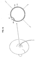
- FIG. 16 is an explanatory diagram for describing a deformation state for when the earpiece according to the related art is placed.
- an earpiece 10 according to the related art shown in FIG. 15A , etc. is connected to a front end of an earphone, etc.
- the earpiece 10 is inserted into a user's ear canal and abuts the ear canal, whereby the earphone is supported by the ear canal.
- description of the earphone is omitted and the earpiece 10 according to the related art will be described.
- the earpiece 10 in the related art has a main unit 12 and a cap portion 14.
- the main unit 12 has a substantially cylindrical shape having a through hole 16 made therein and introduces sound generated by an audio generating unit of the earphone to the user's ear canal.
- the cap portion 14 is formed to extend from a front-end surface (surface in an X-axis position direction) of the main unit 12 to the side of a rear-end surface (surface in an X-axis negative direction) so as to cover the main unit 12, and is thereby formed in a cap-like shape covering the entire main unit 12.
- the cap portion 14 When the earpiece 10 is inserted into the user's ear canal from a front-end surface direction, the cap portion 14 abuts a sidewall of the user's ear canal and thereby supports the main unit 12 and consequently supports the earphone connected to the main unit 12.
- the cap portion 14 not only comes into contact with a user's ear and supports the earphone itself but also acts to improve the fit of the earpiece 10 to the user's ear.
- FIG. 16 shows a cross-sectional shape of the earpiece 10 on a plane vertical to an X-axis, together with an ear canal EH.
- the entire rim of the cap portion 14 of the earpiece 10 be in contact with the ear canal EH so that a uniform pressure F is applied to the entire ear canal EH.
- the size of the ear canal EH varies from person to person. For example, there may be a case in which, as shown in FIG. 16 , since the size of the ear canal EH does not match the size of the cap portion 14, the cap portion 14 distorts. Hence, great pressures F' may be locally applied to the ear canal EH being in contact with the cap portion 14 or there may be an area NF where no pressure is applied.
- unbalancing may occur in pressure applied to the user's ear canal EH. Such unbalancing of pressure may significantly impair fit to the user.
- space SP may be created between the ear canal EH and the cap portion 14, which may cause sound leakage. Such sound leakage possibly influences the quality of sound the user listens to. Accordingly, earpieces require an improvement in fit while such sound leakage is suppressed.
- FIGS. 1A to 1C are explanatory diagrams for describing an example of an earphone to which earpieces according to embodiments of the present invention are applied.
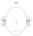
- FIG. 2 is an explanatory diagram for describing a state in which the earphones to which the earpieces according to the embodiments of the present invention are applied are placed.
- FIGS. 1A to 1C are projection views of an earphone 1 as seen from different directions and FIG. 1A is a side view, FIG. 1B is a rear view, and FIG. 1C is a top view.
- earpieces according to the embodiments of the present invention are not limited in its application to an example of an earphone taken here and can be applied to earphones of various modes.
- the earphone 1 has an earpiece 100, a sound conduit 2, a housing 3, a cord holding portion 4, and a cord 5.
- the earpiece 100 is connected to a front end (Y-axis positive and X-axis positive directions) of the sound conduit 2. As shown in FIG. 2 , the earpiece 100 is inserted into a user's ear canal upon placement and abuts an inner wall of the ear canal, whereby the earphone 1 is allowed to maintain a state in which the earpiece 100 is inserted into the user's ear canal. At this time, the earpiece 100, etc., according to the embodiments of the present invention have a configuration that enables to easily improve fit regardless of the size of a user's ear canal and a specific configuration will be described in detail in each embodiment.
- the housing 3 is connected to a rear end of the sound conduit 2 and a through hole that allows sound to be transmitted therethrough is provided between the two ends.
- the housing 3 contains therein a drive unit that originates sound. That is, sound originated from the drive unit contained in the housing 3 is transmitted in a front-end direction through the through hole of the sound conduit 2 and is further transmitted into the ear canal through the earpiece 100.
- the sound conduit 2 is formed to extend inclined in the X-axis positive direction (forward of the user upon placement) with respect to an axis L1 along which the housing 3 is formed. Therefore, when the user places the earphones 1, as shown in FIG.
- the housing 3 is located outside the ear canal near the ear canal.
- the containment space inside the housing 3 can be increased, enabling to improve the sound quality of sound originated from the drive unit.
- the cord holding portion 4 fixes the cord 5 which is connected to the drive unit and pulled out of the housing 3, to the housing 3, and is grasped by the user when the earphone 1 is handled.
- the earphone 1 having such a configuration improves fit by disposing the sound conduit 2 on the outer side of a central position (axis L1) of the housing 3. Namely, as described above, while the earpiece 100 is inserted into the ear canal, the housing 3 fits the shape of the ear near the ear canal, enabling to enhance fit. In addition, the fact that the earphone 1 is supported by the ear using not only the earpiece 100 but also the housing 3 results in enhancement of fit.
- an earphone to which earpieces according to the embodiments of the present invention are applied is not limited to that described above and may be other shapes of earplug type (canal type) earphones.
- earpieces according to the embodiments which will be described below can be used not only as earphones but also as earplugs in the sense of being inserted into ear canals.
- earpieces according to the embodiments are applied to the earphone 1 described in FIG. 1A , etc.
- Earpieces according to the embodiments can significantly improve fit even with other types of earphones (e.g., a type in which a sound conduit is arranged in a front direction (Y-axis positive direction) of a housing); however, when the earpieces are applied to the earphone 1, fit can be improved synergistically with the aforementioned structure.
- other types of earphones e.g., a type in which a sound conduit is arranged in a front direction (Y-axis positive direction) of a housing
- fit can be improved synergistically with the aforementioned structure.
- earpieces according to the embodiments which will be described below further transmit sound transmitted from a sound conduit 2, into an ear canal and the direction in which the sound travels is hereafter referred to as the "front-end surface direction (X-axis positive direction)". That is, a front end, forward, above, etc., indicate directions in which sound travels and a rear end, rearward, and bottom indicate directions opposite to the directions in which sound travels.
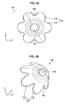
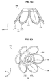
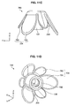
- FIGS. 3A to 3D are explanatory diagrams for describing an earpiece according to a first embodiment of the present invention.
- FIG. 3A is a top view of an earpiece as seen from above (X-axis positive direction) and
- FIG. 3B is a perspective view of the earpiece as seen from diagonally forward (X-axis positive, Y-axis negative, and Z-axis negative directions).
- FIG. 3C is a side view of the earpiece as seen from a lateral direction (Z-axis positive direction) and
- FIG. 3D is a perspective view of the earpiece as seen from diagonally rearward (X-axis negative, Y-axis positive, and Z-axis positive directions).
- the earpiece 100 mainly has a main unit 102 and a cap portion 104.
- the main unit 102 is a structural member that supports the cap portion 104 of an earpiece 100. As shown in FIG. 3D , the main unit 102 has a substantially cylindrical shape and a through hole 108 is provided in a central portion thereof. The through hole 108 is made in a direction in which sound travels (X-axis direction). Sound transmitted through a sound conduit 2 of an earphone 1 is transmitted through the through hole 108. That is, the main unit 102 is connected and fixed to the sound conduit 2 at an end thereof on the rear-end surface side (X-axis negative direction) such that a through hole of the sound conduit 2 and the through hole 108 communicate with each other.
- X-axis negative direction Sound transmitted through a sound conduit 2 of an earphone 1
- the front-end surface side (X-axis positive direction) of the main unit 102 is inserted into an ear canal EH. Therefore, sound originated from a drive unit in a housing 3 of the earphone 1 is sequentially transmitted through the through hole of the sound conduit 2 and the through hole 108 of the main unit 102 and then transmitted into the user's ear canal EH.
- the cap portion 104 is formed to extend from all around the front-end surface, in a direction of providing the through hole 108, of the main unit 102 toward the rear-end surface side. That is, the cap portion 104 of a substantially parabolic shape is formed to extend from a substantially circular end surface, in a direction of insertion into the ear canal EH (X-axis positive direction), of the main unit 102 toward the opposite side of the insertion direction. As shown in FIG. 3A , the cap portion 104 is formed all around the main unit 102 and is formed in a film-like shape covering at least a portion of the main unit 102 on the front-end surface side. At this time, as shown in FIG.
- the cap portion 104 is formed to be spaced apart from the main unit 102 such that a predetermined space is created between the cap portion 104 and the main unit 102, except that a portion of the cap portion 104 on the front-end surface side is connected to the main unit 102.
- the space created between the cap portion 104 and the main unit 102 is set so as to expand at least once as it goes toward the rear-end surface side.
- the space between the cap portion 104 and the main unit 102 in the present embodiment expands as it goes toward the rear-end surface side, the space may be set such that the space expands once and then shrinks.
- the shape of the cap portion 104 is as if a lantern.
- the shape of the cap portion 104 is shown as a substantially parabolic shape.
- the shape of the cap portion 104 can take a variety of shapes as long as the shape can allow the cap portion 104 to be placed in the ear.
- the cap portion 104 may cover the entire main unit 102 or may cover only a part of the main unit 102.
- the cap portion 104 at least one cutting portion 106 is formed.
- FIG. 3A , etc. show the case of forming six cutting portions 106, any number of cutting portions 106 can be formed as long as the number is one or more.
- FIG. 3B shows the case of forming six cutting portions 106, any number of cutting portions 106 can be formed as long as the number is one or more.
- the cap portion 104 is divided into a plurality of cap pieces 110. The cutting portions 106 and the cap pieces 110 will be described.
- the cutting portions 106 are formed in the cap portion 104 so that the cap portion 104 can deform in the direction of the main unit 102. As described above, when two or more cutting portions 106 are formed in the cap portion 104, the cap portion 104 is divided into two or more cap pieces 10. Although in FIGS. 3A to 3D the cutting portions 106 are formed at six locations, the number of the cutting portions 106 is not particularly limited.
- Each of the cutting portions 106 is formed from an end of the cap portion 104 on the rear-end surface side (an end in the X-axis negative direction) toward the front-end surface side along the direction of providing the through hole 108 of the main unit 102. By thus forming the cutting portions 106 in such a direction, the cutting portions 106 can allow the cap portion 104 to deform toward the side of the main unit 102.
- the length in which the cutting portions 106 are formed is set, as shown in FIG. 3C , to be shorter than the length of the cap portion 104 in the direction of forming the cutting portions 106. That is, the cutting portions 106 are formed in a length shorter than the length of the cap portion 104 from the rear-end surface side to the front-end surface side.
- adjacent cap pieces 110 are connected to each other at a front-end portion thereof and thus the strength against external force at the front-end portion, i.e., a base portion of the cap pieces 110 with respect to the main unit 102, is increased.
- the cap pieces 110 can be prevented from excessively deforming or abnormally overlapping each other and also durability can be improved.
- the length of the cutting portions 106 may be appropriately adjusted as shown in a second embodiment which will be described below.
- the cutting portions 106 are formed in a width in which the space between divided cap pieces 110 expands as it goes toward the rear-end surface side.
- an end of each cap piece 110 on the rear-end surface side becomes smaller in a substantially arc-shape manner.
- the material of the cap portion 104 of the earpiece 100 be an elastic material.
- the main unit 102 may also be an elastic member or may be of other materials. Examples of other materials of the main unit 102 include a plastic member, etc.
- the elastic member it is desirable to use silicon rubber but in addition to this a variety of rubbers, e.g., rubbers containing an epoxy resin, a modified silicon resin, and an urethane resin, can be used.
- FIG. 4 is an explanatory diagram for describing effects, etc., of the earpiece 100 according to the present embodiment.
- the earpieces 100 are placed in both ears of the user, needless to say, the earpiece 100 may be placed in only one ear.
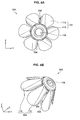
- FIG. 4 is a diagram of a state in which the user places the earphones 1 each including an earpiece 100, as seen from the lateral direction of the user and shows a state in which the earpiece 100 is in contact with an ear canal EH upon the placement.
- FIG. 4 shows a cross-sectional shape of the plurality of cap pieces 110 of the earpiece 100 on a YZ plane.
- each cap piece 110 applies a uniform pressure F to an inner wall surface of the ear canal EH in an outward direction by its moderate elastic force. According to the earpiece 100, the pressures F thus applied to the ear canal EH are uniform and are not unbalanced and thus fit is improved.
- the earpiece 100 unlike the earpiece 10 according to related art, space is not created between the ear canal EH and the earpiece 100. Accordingly, the earpiece 100 can not only prevent local force from being applied to the ear canal EH but also prevent sound leakage. Such effects can be obtained because the earpiece 100 has the cutting portions 106 and thus can distort according to the size of the ear canal EH and contract uniformly without causing abnormal deformation. At this time, the earpiece 100 can deform uniformly supporting various sizes of the ear canal EH and thus can be applied to various users regardless of the size of the ear canal EH.
- the earpiece 100 when the earpiece 100 thus fits into the ear canal EH, an adjustment, etc., are not particularly required and thus the earpiece 100 can easily enhance fit without causing the user any trouble.
- the earpiece 100 has a shape in which, as shown in FIG. 3B , the cap pieces 110 spread out as they go toward the rear-end surface side (X-axis negative direction). Therefore, friction force acts between ends, on the rear-end surface side (X-axis negative direction side), of the respective cap pieces 110 and the ear canal EH, which makes the earpiece 100 difficult to fall out of the ear canal EH.
- the earpiece 100 according to the first embodiment of the present invention is described above.
- the earpiece 100 is described for the case in which the length of the cutting portions 106 formed in the cap portion 104 is set to be shorter than the length of the cap portion 104 in the direction of forming the cutting portions 106.
- the length of the cutting portions 106 can be appropriately adjusted.
- an earpiece 200 according to a second embodiment will be described next.
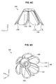
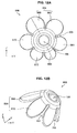
- FIGS. 5A to 5D are explanatory diagrams for describing an earpiece according to a second embodiment of the present invention.
- FIG. 5A is a top view of an earpiece as seen from above (X-axis positive direction) and
- FIG. 5B is a perspective view of the earpiece as seen from diagonally forward (X-axis positive, Y-axis negative, and Z-axis negative directions).
- FIG. 5C is a side view of the earpiece as seen from a lateral direction (Z-axis positive direction) and
- FIG. 5D is a perspective view of the earpiece as seen from diagonally rearward (X-axis negative, Y-axis positive, and Z-axis positive directions).
- An earpiece 200 according to the present embodiment is basically configured in the same manner as the earpiece 100 according to the first embodiment, except that the length of cutting portions 206 is different. Therefore, here, the length of the cutting portions 206 will be mainly described and description of components, etc., that overlap those in the first embodiment is omitted.
- the earpiece 200 has cutting portions 206 instead of the cutting portions 106.
- the cutting portions 206 are basically configured in the same manner as the above-described cutting portions 106 but are different in length than the cutting portions 106.
- the length in which the cutting portions 206 according to the present embodiment are formed is, as shown in FIG. 5C , set to a length comparable with the length of a cap portion 104 in the direction of forming the cutting portions 206. That is, the cutting portions 206 are formed in substantially the same length as the length of the cap portion 104 from the rear-end surface side to the front-end surface side. In other words, the cutting portions 206 of the cap portion 104 are deeper than the cutting portions 106 according to the first embodiment.
- the expression "cutting portions are deeper" as used here indicates a state in which the cutting portions 206 extend longer from an end of the cap portion 104 on the rear-end surface side in the front-end surface side direction (X-axis positive direction).
- each cap piece 110 can reduce its repelling force against external force (force received from an ear canal EH) that causes the cap piece 110 to deform toward the side of the main unit 102, over the case of the first embodiment. Accordingly, pressures F applied to the ear canal EH can be reduced.
- the elastic force of the cap pieces 110 can be adjusted.
- the length of the cutting portions 206 is shorter than the length of the cap portion 104, the strength of a base portion of the cap pieces 110 can be strengthened and thus durability can be improved while abnormal overlapping between the cap pieces 110 is prevented.
- the earpiece 200 according to the second embodiment of the present invention is described above.
- the cap pieces 110 deform toward the side of the main unit 102, whereby uniform, moderate pressures F are applied to the ear canal EH, improving fit.
- the earpieces 100 and 200 according to the first and second embodiments when the size of the ear canal EH is small, adjacent cap pieces 110 overlap with their edge portions. However, since the cap pieces 110 appropriately contract, the pressures F are maintained uniform and thus fit is not impaired.
- the degree of overlapping between the cap pieces 110 can also be controlled regardless of the size of the ear canal EH.
- an earpiece 300 according to a third embodiment of the present invention will be described next.
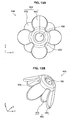
- FIGS. 6A to 6D are explanatory diagrams for describing an earpiece according to a third embodiment of the present invention.
- FIG. 6A is a top view of an earpiece as seen from above (X-axis positive direction) and FIG. 6B is a perspective view of the earpiece as seen from diagonally forward (X-axis positive, Y-axis negative, and Z-axis negative directions).
- FIG. 6C is a side view of the earpiece as seen from a lateral direction (Z-axis positive direction) and
- FIG. 6D is a perspective view of the earpiece as seen from diagonally rearward (X-axis negative, Y-axis positive, and Z-axis positive directions).
- An earpiece 300 according to the present embodiment has extension cap pieces 350.
- the earpiece 300 is configured in the same manner as the earpiece 200 according to the second embodiment, except that the earpiece 300 has the extension cap pieces 350. Therefore, here, the extension cap pieces 350 will be mainly described and description of components, etc., that overlap those in the first and second embodiments is omitted.
- the earpiece 300 has the extension cap pieces 350.
- the extension cap pieces 350 each indicate, as shown in FIG. 6C , a cap piece formed to extend from one cap piece 110 toward another cap piece 110.
- each extension cap piece 350 may be, on one side of a cap piece 110, an edge portion on the side of another cap piece 110 but here description is made assuming that an extension cap piece 350 and a cap piece 110 where the extension cap piece 350 is formed have different configurations.
- An extension cap piece 350 is formed to extend to a cutting portion 206 and thus covers a part of the cutting portion 206.
- each cap piece 110 extends in the direction of a corresponding cutting portion 206 (Y-axis positive direction) and thus the space between cap pieces 110 is narrowed.
- the thickness of each extension cap piece 350 decreases as it goes farther away from a corresponding cap piece 110.
- each extension cap piece 350 becomes thinner as it goes in the direction of a corresponding cutting portion 206 (Y-axis positive direction) from a corresponding cap piece 110.
- FIG. 7 is an explanatory diagram showing a state in which the cap pieces 110 of the earpiece 300 are placed in an ear canal EH.
- the earpiece 300 has the extension cap pieces 350 and thus when the earpiece 300 contracts in the ear canal EH, the cap pieces 110 easily overlap each other.
- the earpiece 300 has the extension cap pieces 350 and thus when the earpiece 300 is placed in the ear, space is less likely to be created between the ear canal EH and the earpiece 300 and accordingly sound leakage is less likely to occur. Furthermore, the thickness of each extension cap piece 350 decreases as it goes farther away from the above-described one cap piece 110. Thus, when a cap portion 104 deforms in the direction of a main unit 102, i.e., when the cap portion 104 is placed in the ear canal EH and contracts, the thickness of a portion where an extension cap piece 350 overlaps the above-described other cap piece 110 does not become thick and thus high quality of sound delivered to the ear is guaranteed. When the earpiece 300 is placed in the ear canal EH and contracts, an extension cap piece 350 may come on the top of the above-described other cap piece 110 or may come under the above-described other cap piece 110.
- the shapes, materials, etc., of components other than the extension cap pieces 350 of the earpiece 300 may be those of the earpiece 100 described with reference to the first embodiment or may be those of the earpiece 200 described with reference to the second embodiment.
- the degree of overlapping between the cap pieces 110 can be adjusted.
- the thickness of each extension cap piece 350 decreases as it goes farther away from a corresponding cap piece 110, even when the extension cap piece 350 overlaps another cap piece 110, the thickness of the overlapping portion does not become thick more than necessary and thus high quality of sound is also guaranteed.
- the earpiece 300 according to the third embodiment of the present invention is described above.
- the cap pieces 110 deform toward the side of the main unit 102, whereby uniform, moderate pressures F are applied to the ear canal EH, improving fit.
- the earpiece 300 according to the third embodiment has the extension cap pieces 350, which enables to control the degree of overlapping between the cap pieces 110.
- the degree of overlapping between the cap pieces 110 can also be controlled by providing connecting films 450 that connect the cap pieces 110 divided by the cutting portions 206 (or the cutting portions 106).
- an earpiece 400 according to a fourth embodiment of the present invention will be described.
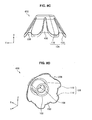
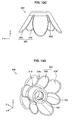
- FIGS. 8A to 8D are explanatory diagrams for describing an earpiece according to a fourth embodiment of the present invention.
- FIG. 8A is a top view of an earpiece as seen from above (X-axis positive direction) and FIG. 8B is a perspective view of the earpiece as seen from diagonally forward (X-axis positive, Y-axis negative, and Z-axis negative directions).
- FIG. 8C is a side view of the earpiece as seen from a lateral direction (Z-axis positive direction) and
- FIG. 8D is a perspective view of the earpiece as seen from diagonally rearward (X-axis negative, Y-axis positive, and Z-axis positive directions).
- An earpiece 400 according to the present embodiment has connecting films 450.
- the earpiece 400 is configured in the same manner as the earpiece 200 according to the second embodiment, except that the earpiece 400 has the connecting films 450. Therefore, here, the connecting films 450 will be mainly described and description of components, etc., that overlap those in the first and second embodiments is omitted.
- the earpiece 400 has the connecting films 450, each of which connects two cap pieces 110 divided by a cutting portion 206 (or cutting portion 106).
- the connecting films 450 are formed in their corresponding cutting portions 206, to a thickness thinner than a cap portion 104.
- the connecting films 450 may be of the same material as the cap pieces 110 or may be of a material that provides easy fabrication with a thin thickness.
- the material may be silicon rubber as with the cap pieces 110 or may be urethane rubber which has strong tensile strength even when it is thin.
- the earpiece 400 thus has the connecting films 450 in areas where the cutting portions 206 are present, when the earpiece 400 contracts in an ear canal EH, space is less likely to be created.
- the connecting films 450 since the thickness is thin, the connecting films 450 more easily distort than the cap pieces 110 in terms of deformation in the direction of a main unit 102.
- the earpiece 400 since the earpiece 400 has the connecting films 450, deformation of the divided cap pieces 110 is more accurately controlled. In other words, the direction in which the earpiece 400 shrinks when contracting in the ear canal EH is controlled.
- cap pieces 110 are connected to each other through a connecting film 450 and the cap pieces 110 deform in conjunction with one another, for example, one cap piece 110 is less likely to overlap another cap piece 110 adjacent thereto. From this point of view, too, space is less likely to be created between the earpiece 400 and the ear canal EH.
- the shapes, materials, etc., of components other than the connecting films 450 of the earpiece 400 may be any of those of the earpiece 100, etc., described with reference to the first to third embodiments.
- the earpiece 400 according to the fourth embodiment of the present invention is descried above.
- the cap pieces 110 deform toward the side of the main unit 102, whereby uniform, moderate pressures F are applied to the ear canal EH, improving fit.
- the earpiece 400 according to the fourth embodiment has the connecting films 450, which enables to control the degree of overlapping between the cap pieces 110. It is desirable that when the earpiece 400 is placed in the ear canal EH the connecting films 450 contract to the center side of the ear canal EH.
- connecting films 550 that easily contract to the center side of the ear canal EH
- an earpiece 500 according to a fifth embodiment of the present invention will be described.
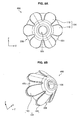
- FIGS. 9A to 9D are explanatory diagrams for describing an earpiece according to a fifth embodiment of the present invention.
- FIG. 9A is a top view of an earpiece as seen from above (X-axis positive direction) and
- FIG. 9B is a perspective view of the earpiece as seen from diagonally forward (X-axis positive, Y-axis negative, and Z-axis negative directions).
- FIG. 9C is a side view of the earpiece as seen from a lateral direction (Z-axis positive direction) and
- FIG. 9D is a perspective view of the earpiece as seen from diagonally rearward (X-axis negative, Y-axis positive, and Z-axis positive directions).
- An earpiece 500 according to the present embodiment has connecting films 550.
- the earpiece 500 is configured in the same manner as the earpiece 200 according to the second embodiment, except that the earpiece 500 has the connecting films 550. Therefore, here, the connecting films 550 will be mainly described and description of components, etc., that overlap those in the first and second embodiments is omitted.
- the connecting films 550 of the earpiece 500 are fold-like films.
- the word "fold-like" as used here indicates, as shown in FIG. 9D , a state of bending toward the side of a main unit 102. Since the connecting films 550 are provided in areas where cutting portions 206 are present, when the earpiece 500 contracts in an ear canal EH, space is less likely to be created. In addition, since the thickness is thin, the connecting films 550 more easily distort than cap pieces 110 in terms of deformation in the direction of the main unit 102. Furthermore, since the connecting films 550 bend toward the side of the main unit 102, when the earpiece 500 contracts in the ear canal EH, the connecting films 550 easily deform toward the side of the main unit 102 (the center side of the earpiece 500).
- connecting films 550 thus bend toward the side of the main unit 102, when the earpiece 500 contracts in the ear canal EH, the connecting films 550 deform toward the side of the main unit 102 and thus no pressure from the connecting films 550 is applied to the ear canal EH. Hence, a load is less likely to be applied to the ear canal EH.
- providing the connecting films 550 makes space less likely to be created between the earpiece 500 and the ear canal EH.
- the shapes, materials, etc., of components other than the connecting films 550 of the earpiece 500 according to the present embodiment may be any of those of the earpiece 100, etc., described with reference to the first to fourth embodiments.
- the connecting films 550 of the earpiece 500 according to the present embodiment have the same configuration as the connecting films 450 of the earpiece 400 according to the fourth embodiment, except that the connecting films 550 bend toward the side of the main unit 102.
- the earpiece 500 according to the fifth embodiment of the present invention is described above.
- the cap pieces 110 deform toward the side of the main unit 102, whereby uniform, moderate pressures F are applied to the ear canal EH, improving fit.
- the pressures F applied to the ear canal EH are more stabilized, which also enables to improve fit.
- an earpiece 600 according to a sixth embodiment of the present invention will be described next.
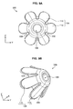
- FIGS. l0A to 10D are explanatory diagrams for describing an earpiece according to a sixth embodiment of the present invention.
- FIG. 10A is a top view of an earpiece as seen from above (X-axis positive direction) and FIG. 10B is a perspective view of the earpiece as seen from diagonally forward (X-axis positive, Y-axis negative, and Z-axis negative directions).
- FIG. 10C is a side view of the earpiece as seen from a lateral direction (Z-axis positive direction) and
- FIG. 10D is a perspective view of the earpiece as seen from diagonally rearward (X-axis negative, Y-axis positive, and Z-axis positive directions).
- An earpiece 600 according to the present embodiment has supporting portions 650, as shown in FIG. 10D .
- the earpiece 600 is configured in the same manner as the earpiece 200 according to the second embodiment, except that the earpiece 600 has the supporting portions 650. Therefore, here, the supporting portions 650 will be mainly described and description of components, etc., that overlap those in the first and second embodiments is omitted.
- the supporting portions 650 of the earpiece 600 are present between a main unit 102 and a cap portion 104 and near a connecting location of a front-end surface of the main unit 102 to the cap portion 104.
- the "near a connecting location” may be a location that is closest to the connecting location of the main unit 102 to the cap portion 104 or may be a location spaced somewhat from the connecting location of the main unit 102 to the cap portion 104.
- the supporting portions 650 have a shape supporting the cap portion 104 and act as ribs. As shown in FIG. 10D , the supporting portions 650 are present at respective cap pieces 110 but are not necessarily need to be present at the respective cap pieces 110.
- a supporting portion 650 may be present at only one cap piece 110 or supporting portions 650 may be present at every other cap piece 110.
- the supporting portions 650 are disposed at locations that do not overlap the locations of cutting portions 206.
- the supporting portions 650 may be of the same material as the cap pieces 110 or may be of a material having a large elastic force.
- the material may be silicon rubber as with the cap pieces 110 or may be urethane rubber having a large elastic force.
- the supporting portions 650 can strengthen the elastic forces of the cap pieces 110.
- pressure applied to an ear canal EH increases.
- the cap portion 104 contracts while providing a repelling force to the ear canal EH by its elastic force.
- space is less likely to be created between the earpiece 600 and the ear canal EH and thus there is no sound leakage and accordingly the user can obtain good fit.
- the shapes, materials, etc., of components other than the supporting portions 650 of the earpiece 600 according to the present embodiment may be those of the earpiece 100, etc., according to the first to fifth embodiments.
- the earpiece 600 according to the sixth embodiment of the present invention is descried above.
- the cap pieces 110 deform toward the side of the main unit 102, whereby uniform, moderate pressures F are applied to the ear canal EH, improving fit.
- the earpiece 600 according to the sixth embodiment has the supporting portions 650, which enables more stable control of the cap pieces 110 in the direction of the main unit 102.
- the cap pieces 110 all have the same size, the size does not need to be the same for all the cap pieces 110.
- an earpiece 700 according to a seventh embodiment of the present invention will be described.
- FIGS. 11A to 11D are explanatory diagrams for describing an earpiece according to a seventh embodiment of the present invention.
- FIG. 11A is a top view of an earpiece as seen from above (X-axis positive direction) and FIG. 11B is a perspective view of the earpiece as seen from diagonally forward (X-axis positive, Y-axis negative, and Z-axis negative directions).
- FIG. 11C is a side view of the earpiece as seen from a lateral direction (Z-axis positive direction) and
- FIG. 11D is a perspective view of the earpiece as seen from diagonally rearward (X-axis negative, Y-axis positive, and Z-axis positive directions).
- An earpiece 700 according to the present embodiment has a cap portion 704.
- the cap portion 704 has, as shown in FIG. 11A , larger cap pieces 750 and smaller cap pieces 760.
- the earpiece 700 is configured in the same manner as the earpiece 200 according to the second embodiment, except that the earpiece 700 has, instead of the cap portion 104, the cap portion 704 including the larger cap pieces 750 and the smaller cap pieces 760. Therefore, here, the cap portion 704 including the larger cap pieces 750 and the smaller cap pieces 760 will be mainly described and description of components, etc., that overlap those in the first and second embodiments is omitted.
- the cap portion 704 of the earpiece 700 has cap pieces having different sizes, i.e., the larger cap pieces 750 and the smaller cap pieces 760.
- the larger cap pieces 750 and the smaller cap pieces 760 are disposed alternately.
- the earpiece 700 contracts in an ear canal EH, the larger cap pieces 750 overlap one another.
- the smaller cap pieces 760 deform so as not to create space between the larger cap pieces 750.
- the smaller cap pieces 760 can act to prevent the larger cap pieces 158 from making unwanted move. Specifically, in order that when the larger cap pieces 750 deform in the direction of a main unit 102 the larger cap pieces 750 do not overlap one another too much, the smaller cap pieces 760 can prevent the larger cap pieces 750 from deforming in directions other than the direction of the main unit 102 (the direction of the center of the earpiece 700). That is, the smaller cap pieces 760 can serve as supporting portions for the larger cap pieces 750.
- the shapes, materials, etc., of components other than the cap portion 704 of the earpiece 700 may be those of the earpiece 100, etc., according to the first to sixth embodiments.
- the earpiece 700 according to the seventh embodiment of the present invention is described above.
- the cap pieces 750 and 760 deform toward the side of the main unit 102, whereby uniform, moderate pressures F are applied to the ear canal EH, improving fit.
- the cap portion 704 can stably deform in the direction of the main unit 102.
- an example in which the sizes of the cap pieces 750 and 760 differ from cap piece to cap piece is not limited to the cap pieces 750 and 760 of the earpiece 700 according to the present embodiment. Namely, the cap pieces 750 and 760 can take random sizes and shapes.
- a cap piece 862, etc. have different sizes
- an earpiece 800 according to an eighth embodiment of the present invention will be described.
- FIGS. 12A to 12D are explanatory diagrams for describing an earpiece according to an eighth embodiment of the present invention.
- FIG. 12A is a top view of an earpiece as seen from above (X-axis positive direction) and FIG. 12B is a perspective view of the earpiece as seen from diagonally forward (X-axis positive, Y-axis negative, and Z-axis negative directions).
- FIG. 12C is a side view of the earpiece as seen from a lateral direction (Z-axis positive direction) and
- FIG. 12D is a perspective view of the earpiece as seen from diagonally rearward (X-axis negative, Y-axis positive, and Z-axis positive directions).
- An earpiece 800 according to the present embodiment has a cap portion 804.
- the cap portion 804 has a cap piece 862, a cap piece 864, a cap piece 866, a cap piece 868, a cap piece 870, and a cap piece 872.
- the earpiece 800 is configured in the same manner as the earpiece 200 according to the second embodiment, except that the earpiece 800 has, instead of the cap portion 104, the cap portion 804 having the cap piece 862, the cap piece 864, the cap piece 866, the cap piece 868, the cap piece 870, and the cap piece 872.
- the cap portion 804 including the cap piece 862, the cap piece 864, the cap piece 866, the cap piece 868, the cap piece 870, and the cap piece 872 will be mainly described and description of components, etc., that overlap those in the first and second embodiments is omitted.
- the cap piece 862, the cap piece 864, the cap piece 866, the cap piece 868, the cap piece 870, and the cap piece 872 of the earpiece 800 differ in size between the cap pieces.
- the size gradually decreases in order of the cap piece 862, the cap piece 864, and the cap piece 866.
- the size gradually decreases in order of the cap piece 868, the cap piece 870, and the cap piece 872.
- the size indicates an area and also indicates the length in a rear-end surface side direction (X-axis negative direction).
- the earpiece 800 When the earpiece 800 according to the present embodiment contracts in an ear canal EH, an area of the cap portion 804 that comes into contact with the ear canal EH varies between the cap pieces 862, 864, 866, 868, 870, and 872. In a state in which the user is standing, the user's ear canal EH is not parallel to the ground but has little inclination. Therefore, the earpiece 800 having the cap pieces 862, 864, 866, 868, 870, and 872 with different sizes can be placed in the ear canal EH with an inclination of the same level as the above-described inclination. As a result, the user can also obtain very good fit without sensing variations in pressure F between locations in the ear canal EH.
- the shapes, materials, etc., of components other than the cap portion 804 of the earpiece 800 may be those of the earpiece 100, etc., according to the first to seventh embodiments.
- the earpiece 800 according to the eighth embodiment of the present invention is described above.
- the cap pieces 862, 864, 866, 868, 870, and 872 deform toward the side of a main unit 102, whereby uniform, moderate pressures F are applied to the ear canal EH, improving fit.
- the user can also obtain very good fit without sensing variations in pressure F between locations in the ear canal EH.
- cap pieces have different sizes is not limited to the cap pieces 862, 864, 866, 868, 870, and 872 of the earpiece 800 according to the present embodiment. Namely, the cap pieces 862, 864, 866, 868, 870, and 872 can take random sizes and shapes.
- the cap portion 104, etc. all have a single-layer structure
- the cap portion 104, etc. do not necessarily need to have a single-layer structure.
- an earpiece 900 according to a ninth embodiment of the present invention will be described.
- FIGS. 13A to 13D are explanatory diagrams for describing an earpiece according to a ninth embodiment of the present invention.
- FIG. 13A is a top view of an earpiece as seen from above (X-axis positive direction) and
- FIG. 13B is a perspective view of the earpiece as seen from diagonally forward (X-axis positive, Y-axis negative, and Z-axis negative directions).
- FIG. 13C is a side view of the earpiece as seen from a lateral direction (Z-axis positive direction) and
- FIG. 13D is a perspective view of the earpiece as seen from diagonally rearward (X-axis negative, Y-axis positive, and Z-axis positive directions).
- An earpiece 900 according to the present embodiment has a cap portion 982.
- the earpiece 900 is configured in the same manner as the earpiece 200 according to the second embodiment, except that the earpiece 900 has the cap portion 982 instead of the cap portion 104. Therefore, the cap portion 982 will be mainly described and description of components, etc., that overlap those in the first and second embodiments is omitted.
- the cap portion 982 is formed of a two-layer structure having first cap pieces 978, first cutting portions 916, second cap pieces 980, and second cutting portions 906.
- the cap portion 982 of the earpiece 900 is formed of a two-layer structure in which two layers are stacked on top of each other in a thickness direction so as to be spaced apart from each other.
- the cap portion 982 has a film-like shape covering a portion of a main unit 102 on the front-end surface side (the side, in an X-axis positive direction, of the main unit 102).
- the cap portion 982 has a shape in which the space between the main unit 102 and the cap portion 982 expands at least once as it goes in an X-axis negative direction. Furthermore, each cutting portion 916 adjacent to a first cap piece 978 and each cutting portion 906 adjacent to a second cap piece 980 are respectively formed at locations where they do not overlap each other.
- the earpiece 900 having the cap portion 982 having a two-layer structure is exemplified
- the cap portion 982 may have a multi-layer structure other than a two-layer structure.
- the structure may be a three-layer structure or may be a four-layer structure or may be an n-layer structure (n: a natural number).
- an earpiece having a 10-layer structure has value not only as being placed in an ear but also as an ornament because it has a shape like a sea anemone and thus has a fine appearance.
- the shapes, materials, etc., of components other than the cap portion 982 of the earpiece 900 may be those of the earpiece 100, etc., according to the first to eighth embodiments.
- each first cutting portion 916 and each second cutting portion 906 are respectively formed at locations where they do not overlap each other.
- the first cutting portions 916 and the second cap pieces 980 have an overlapping positional relationship.
- the second cutting portions 906 and the first cap pieces 978 have an overlapping positional relationship. Therefore, when the earpiece 900 is placed in the ear canal EH, space is less likely to be created between the ear canal EH and the earpiece 900.
- the second cap pieces 980 are less likely to similarly deform in the direction other than the direction of the main unit 102 in conjunction with the first cap pieces 978.
- space is less likely to be created between the ear canal EH and the earpiece 900.
- the earpiece 900 according to the ninth embodiment of the present invention is described above.
- the cap portion 982 deforms toward the side of the main unit 102, whereby uniform, moderate pressures F are applied to the ear canal EH, improving fit.
- the earpiece 900 according to the present embodiment since the earpiece 900 has the cap portion 982 having a two-layer structure, space is less likely to be created between the ear canal EH and the earpiece 900.
- the cap portion 104, etc. are divided into the cap pieces 110, etc., by the cutting portions 206, etc.
- the cap portion 104, etc. do not necessarily need to be structured to be divided into the cap pieces 110, etc., by the cutting portions 206, etc.
- an earpiece 1100 according to a tenth embodiment of the present invention will be described.
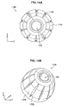
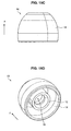
- FIGS. 14A to 14D are explanatory diagrams for describing an earpiece according to a tenth embodiment of the present invention.
- FIG. 14A is a top view of an earpiece as seen from above (X-axis positive direction) and
- FIG. 14B is a perspective view of the earpiece as seen from diagonally forward (X-axis positive, Y-axis negative, and Z-axis negative directions).
- FIG. 14C is a side view of the earpiece as seen from a lateral direction (Z-axis positive direction) and
- FIG. 14D is a perspective view of the earpiece as seen from diagonally rearward (X-axis negative, Y-axis positive, and Z-axis positive directions).
- a cap portion 1104 has cutting portions 1106. As shown in FIG. 14C , in an earpiece 1100, cuttings of the cutting portions 1106 are formed in a direction of making a through hole of a main unit 102, i.e., in an X-axis negative direction. The cuttings, however, are not formed all the way to the most rear-end side of the cap portion 1104 (the side, in a most X-axis negative direction, of the cap portion 1104). That is, the cutting portions 1106 of the earpiece 1100 make through holes in the cap portion 1104.
- the cap portion 1104 Since in the earpiece 1100 the cap portion 1104 has through holes made therein without being divided, even when, for example, the earpiece 1100 receives a shock, the cap portion 1104 is less likely to spread out and thus excellent durability is provided.
- the shapes, materials, etc., of components other than the cap portion 1104 of the earpiece 1100 which is not divided may be those of the earpiece 100 described with reference to FIG. 1 .
- the shapes and lengths of cuttings do not need to be all the same and some of them may be different or all of them may be different.
- the earpiece 1100 according to the tenth embodiment of the present invention is described above.
- the cap portion 1104 deforms toward the side of the main unit 102, whereby uniform, moderate pressures F are applied to an ear canal EH, improving fit.
- the cap portion 1104 since through holes are made in the cutting portions 1106 without the cap portion 1104 being divided, even when, for example, the earpiece 1100 receives a shock, the cap portion 1104 is less likely to spread out and thus excellent durability is provided.
- the earpieces have a main unit and a cap portion.
- the main unit has a cylindrical shape having made therein a through hole that can allow sound to be transmitted therethrough.
- the cap portion has a film-like shape which is formed to extend from all around a front-end surface, in a direction of making the through hole, of the main unit toward a rear-end surface side, and which covers at least a portion of the main unit on the front-end surface side, and in which space between the main unit and the cap portion expands as it goes toward the rear-end surface side.
- the earpiece has at least one cutting portion formed in the cap portion so that the cap portion can deform in a direction of the main unit.
- the earpiece since the earpiece has a cutting portion in a cap portion, when the earpiece is placed in an ear canal, the cap portion deforms in a direction of a main unit along the shape of an inner wall surface of the ear canal. Thus, without applying local force to the user's ear canal, fit can be improved. In addition, when the cap portion deforms in the direction of the main unit, space created by the cutting portion decreases and thus sound leakage is kept to a minimum. Accordingly, fit can be improved without degrading sound quality. Such effects can be obtained because the earpiece has the cutting portion and thus can contract according to the size of the ear canal and such abnormal deformation does not occur that applies local pressure to the ear canal. As such, the earpiece having the above-descried configuration can deform fitting in various ear canal sizes.
- At least two cutting portions of the earpiece may be formed from an end of the cap portion on the rear-end surface side toward the front-end surface side, and the cap portion may be divided into two or more cap pieces which are connected to each other on the front-end surface side.
- the cap portion is divided into two or more cap pieces, the cap pieces easily overlap each other and thus the earpiece can more stably contract without causing abnormal deformation in the ear canal.
- the above-described earpiece may be such that in at least one cutting portion is formed an extension cap piece that is formed to extend from one of cap pieces divided by the cutting portion toward an other cap piece and that covers a part of the cutting portion, and a thickness of the extension cap piece decreases as it goes farther away from the one cap piece, so that the extension cap piece overlaps the other cap piece when the cap portion deforms in the direction of the main unit.
- the extension cap piece overlaps an adjacent cap piece (other cap piece), decreasing space created by the cutting portion between cap pieces. As a result, the possibility of occurrence of sound leakage can be further reduced.
- the above-described earpiece may further include a connecting film that is formed in the at least one cutting portion, to a thickness thinner than the cap portion and that connects two cap pieces divided by the cutting portion.
- a connecting film is formed in a cutting portion between cap pieces, when the cap portion contracts toward the main unit side upon placement, space created by the cutting portion can be further reduced. Thus, sound leakage can be further prevented and sound quality can be further improved.
- the cap pieces are connected to each other through the connecting film and deform in conjunction with each other. Thus, since a plurality of cap pieces can uniformly deform through the connecting film, for example, one cap piece can be prevented from overlapping another cap piece adjacent thereto more than necessary or abnormal deformation can be prevented from occurring. This fact can provide not only the aforementioned improvement in sound quality, etc., but also an effect of enhancement of fit by reducing local pressure applied to the ear canal.
- the connecting film may have a shape bending toward a side of the main unit between the two divided cap pieces.
- the connecting film bends toward the main unit side, when the earpiece is placed, the connecting film can further bend in the bending direction.
- abnormal deformation of the connecting film itself can be prevented.
- a load is less likely to be applied to the ear canal and also sound leakage is less likely to occur.
- the above-described earpiece may further include a supporting portion between the main unit and the cap portion near a connecting location of the front-end surface of the main unit to the cap portion, the supporting portion supporting the cap portion.
- a supporting portion can strengthen an elastic force at the base of a cap piece. Therefore, when a user places the earpiece in his/her ear canal, the cap portion contracts while providing a repelling force to the ear by its elastic force, whereby space between the cap portion and the ear canal is reduced and sound leakage can be prevented and fit can be improved. It is desirable that the cap pieces, etc., be formed by elastic members but the elastic force of the elastic members may decrease due to deterioration over time or excess deformation. On the other hand, when a supporting portion is formed, as in the above-described configuration, such a decrease in elastic force can be compensated for, which can in turn improve the durability of the earpiece.
- the cap portion may have a multi-layer structure in which layers are stacked on top of each other in a thickness direction so as to be spaced apart from each other, and the cutting portion may be formed at different locations for the different layers.
- the cutting portions do not overlap each other, enabling to further reduce space created by the cutting portions.
- an auxiliary cap piece adjacent thereto is less likely to similarly deform in the direction other than the direction of the main unit in conjunction with the cap piece. This fact can also make space less likely to be created between the ear canal and the earpiece when the earpiece is placed in the ear canal.
- the cutting portion may be formed in a portion of the cap portion between the rear-end surface side and the front-end surface side to make a through hole in the cap portion in the direction of making the through hole.
- the cap portion is not divided, even when the earpiece receives a shock, the cap pieces are less likely to spread out, enabling to improve durability.
- the cutting portions may be formed in a width in which space between the divided cap pieces expands as it goes toward the rear-end surface side.
- the cap pieces do not overlap each other more than necessary and thus fit can be further improved.
- the cutting portions may be formed in a length shorter than a length of the cap portion from the rear-end surface side to the front-end surface side.
- the cap pieces when the earpiece is placed in the ear canal and contracts, the cap pieces are less likely to deform in directions other than the direction of the main unit.
- the cap pieces are connected to each other and thus the strength of the base portion of the cap pieces is increased. Accordingly, abnormal deformation such as excess deformation of the cap pieces can be prevented.
- embodiments of the present invention are not limited thereto. Namely, one cutting portion 106 may be formed in the cap portion 104.
- the cap portion 104 is not divided into a plurality of cap pieces 110, smooth deformation toward the side of a main unit 102 is enabled by the cutting portion 106 and thus fit can be improved.
Landscapes
- Physics & Mathematics (AREA)
- Engineering & Computer Science (AREA)
- Acoustics & Sound (AREA)
- Signal Processing (AREA)
- Headphones And Earphones (AREA)
Abstract
Description
- The present invention relates to an earpiece and an earphone.
- In recent years, portable audio playback apparatuses have widely proliferated. The audio playback apparatuses output audio from earphones, for example, and thereby provide the sound to users. For the earphones, various types are available and the taste of earphones often varies from user to user. As an example of the earphones, numbers of earphones, called earplug type (canal type), are commercialized in which an earpiece is attached to a front end of a sound conduit. However, the size of an ear canal varies from user to user. Thus, when the user places an earphone, if the size of an earpiece is small, there is more sound leakage, degrading sound quality. On the other hand, when the user places an earphone, if the size of an earpiece is large, it is difficult to put the earpiece in an ear canal, which may even cause pain in the ear canal. In view of this, in an earphone described in, for example, Japanese Patent No.
3815513 - However, when the user buys an earphone such as that described above, the user has to buy unnecessary earpieces of a plurality of sizes which may not be used, too, increasing the price of products. In view of this, earpieces are developed that can be applied to people with different sizes of ears, with one earpiece without attaching a plurality of types of earpieces. In this earpiece, each cap portion which abuts a user's ear is formed by a plurality of stages with different sizes, which enables to support the size of a user's ear canal. With such an earpiece, however, many users get an uncomfortable feeling in fit, e.g., stages that do not match the size of a user's ear canal press the user's ear canal, and thus earpieces with further improved fit are sought.
- As shown in Japanese Patent Application Laid-Open No.
8-98290 - In light of the foregoing, it is desirable to provide a novel and improved earpiece and earphone that can be easily placed and can improve fit for various users with different sizes of ear canales without preparing a plurality of sizes.
Various respective aspects and features of the invention are defined in the appended claims. Combinations of features from the dependent claims may be combined with features of the independent claims as appropriate and not merely as explicitly set out in the claims. - According to an embodiment of the present invention, there is provided an earpiece comprising: a main unit having a cylindrical shape having made therein a through hole that can allow sound to be transmitted therethrough; a cap portion that has a film-like shape which is formed to extend from all around a front-end surface, in a direction of making the through hole, of the main unit toward a rear-end surface side, and which covers at least a portion of the main unit on the front-end surface side, and in which space between the main unit and the cap portion expands as it goes toward the rear-end surface side; and at least one cutting portion formed in the cap portion so that the cap portion can deform in a direction of the main unit.
- At least two cutting portions may be formed from an end of the cap portion on the rear-end surface side toward the front-end surface side, and the cap portion may be divided into two or more cap pieces which are connected to each other on the front-end surface side.
- In the at least one cutting portion may be formed an extension cap piece that is formed to extend from one of cap pieces divided by the cutting portion toward an other cap piece and that covers a part of the cutting portion, and
a thickness of the extension cap piece decreases as it goes farther away from the one cap piece, so that the extension cap piece overlaps the other cap piece when the cap portion deforms in the direction of the main unit. - The earpiece may further comprise a connecting film that is formed in the at least one cutting portion, to a thickness thinner than the cap portion and that connects two cap pieces divided by the cutting portion.
- The earpiece connecting film may have a shape bending toward a side of the main unit between the two divided cap pieces.
- The earpiece may further comprise a supporting portion between the main unit and the cap portion near a connecting location of the front-end surface of the main unit to the cap portion, the supporting portion supporting the cap portion.
- The earpiece cap portion may have a multi-layer structure in which layers are stacked on top of each other in a thickness direction so as to be spaced apart from each other, and the cutting portion may be formed at different locations for the different layers.
- The cutting portion may be formed in a portion of the cap portion between the rear-end surface side and the front-end surface side to make a through hole in the cap portion in the direction of making the through hole.
- The cutting portions may be formed in a width in which space between the divided cap pieces expands as it goes toward the rear-end surface side.
- The cutting portions may be formed in a length shorter than a length of the cap portion from the rear-end surface side to the front-end surface side.
- According to another embodiment of the present invention, there is provided an earphone comprising: a drive unit that originates sound; and an earpiece that transmits the sound originated from the drive unit into an ear canal while being inserted into an ear of a listener and thereby supporting the drive unit, wherein the earpiece includes: a main unit having a cylindrical shape having made therein a through hole that communicates between the drive unit and the ear canal; a cap portion that has a film-like shape which is formed to extend from all around a front-end surface, in a direction of making the through hole, of the main unit toward a rear-end surface side, and which covers at least a portion of the main unit on the front-end surface side, and in which space between the main unit and the cap portion expands as it goes toward the rear-end surface side; and at least one cutting portion formed in the cap portion so that the cap portion can deform in a direction of the main unit.
- As described above, according to embodiments of the present invention, an earpiece and an earphone can be easily placed and fit can be improved for various users with different sizes of ear canals without preparing a plurality of sizes.
- Embodiments of the invention will now be described, by way of example only, with reference to the accompanying drawings in which:
-
FIG. 1A is an explanatory diagram for describing an example of an earphone to which earpieces according to embodiments of the present invention are applied; -
FIG. 1B is an explanatory diagram for describing an example of an earphone to which earpieces according to embodiments of the present invention are applied; -
FIG. 1C is an explanatory diagram for describing an example of an earphone to which earpieces according to embodiments of the present invention are applied; -
FIG. 2 is an explanatory diagram for describing a state in which the earphone to which the earpieces according to the embodiments of the present invention are applied is placed; -
FIG. 3A is an explanatory diagram for describing an earpiece according to a first embodiment of the present invention; -
FIG. 3B is an explanatory diagram for describing the earpiece according to the embodiment; -
FIG. 3C is an explanatory diagram for describing the earpiece according to the embodiment; -
FIG. 3D is an explanatory diagram for describing the earpiece according to the embodiment; -
FIG. 4 is an explanatory diagram for describing effects, etc., of the earpiece according to the embodiment; -
FIG. 5A is an explanatory diagram for describing an earpiece according to a second embodiment of the present invention; -
FIG. 5B is an explanatory diagram for describing the earpiece according to the embodiment; -
FIG. 5C is an explanatory diagram for describing the earpiece according to the embodiment; -
FIG. 5D is an explanatory diagram for describing the earpiece according to the embodiment; -
FIG. 6A is an explanatory diagram for describing an earpiece according to a third embodiment of the present invention; -
FIG. 6B is an explanatory diagram for describing the earpiece according to the embodiment; -
FIG. 6C is an explanatory diagram for describing the earpiece according to the embodiment; -
FIG. 6D is an explanatory diagram for describing the earpiece according to the embodiment; -
FIG. 7 is an explanatory diagram for describing effects, etc., of the earpiece according to the embodiment; -
FIG. 8A is an explanatory diagram for describing an earpiece according to a fourth embodiment of the present invention; -
FIG. 8B is an explanatory diagram for describing the earpiece according to the embodiment; -
FIG. 8C is an explanatory diagram for describing the earpiece according to the embodiment; -
FIG. 8D is an explanatory diagram for describing the earpiece according to the embodiment; -
FIG. 9A is an explanatory diagram for describing an earpiece according to a fifth embodiment of the present invention; -
FIG. 9B is an explanatory diagram for describing the earpiece according to the embodiment; -
FIG. 9C is an explanatory diagram for describing the earpiece according to the embodiment; -
FIG. 9D is an explanatory diagram for describing the earpiece according to the embodiment; -
FIG. 10A is an explanatory diagram for describing an earpiece according to a sixth embodiment of the present invention; -
FIG. 10B is an explanatory diagram for describing the earpiece according to the embodiment; -
FIG. 10C is an explanatory diagram for describing the earpiece according to the embodiment; -
FIG. 10D is an explanatory diagram for describing the earpiece according to the embodiment; -
FIG. 11A is an explanatory diagram for describing an earpiece according to a seventh embodiment of the present invention; -
FIG. 11B is an explanatory diagram for describing the earpiece according to the embodiment; -
FIG. 11C is an explanatory diagram for describing the earpiece according to the embodiment; -
FIG. 11D is an explanatory diagram for describing the earpiece according to the embodiment; -
FIG. 12A is an explanatory diagram for describing an earpiece according to a eighth embodiment of the present invention; -
FIG. 12B is an explanatory diagram for describing the earpiece according to the embodiment; -
FIG. 12C is an explanatory diagram for describing the earpiece according to the embodiment; -
FIG. 12D is an explanatory diagram for describing the earpiece according to the embodiment; -
FIG. 13A is an explanatory diagram for describing an earpiece according to a ninth embodiment of the present invention; -
FIG. 13B is an explanatory diagram for describing the earpiece according to the embodiment; -
FIG. 13C is an explanatory diagram for describing the earpiece according to the embodiment; -
FIG. 13D is an explanatory diagram for describing the earpiece according to the embodiment; -
FIG. 14A is an explanatory diagram for describing an earpiece according to a tenth embodiment of the present invention; -
FIG. 14B is an explanatory diagram for describing the earpiece according to the embodiment; -
FIG. 14C is an explanatory diagram for describing the earpiece according to the embodiment; -
FIG. 14D is an explanatory diagram for describing the earpiece according to the embodiment; -
FIG. 15A is an explanatory diagram for describing the configuration of an earpiece according to the related art; -
FIG. 15B is an explanatory diagram for describing the configuration of the earpiece according to the related art; -
FIG. 15C is an explanatory diagram for describing the configuration of the earpiece according to the related art; -
FIG. 15D is an explanatory diagram for describing the configuration of the earpiece according to the related art; and -
FIG. 16 is an explanatory diagram for describing a deformation state for when an earpiece according to related art is placed. - Hereinafter, preferred embodiments of the present invention will be described in detail with reference to the appended drawings. Note that, in this specification and the appended drawings, structural elements that have substantially the same function and structure are denoted with the same reference numerals, and repeated explanation of these structural elements is omitted.
- In an earpiece according to one embodiment of the present invention, a cap portion which abuts a user's ear canal upon placement deforms according to the shape of the user's ear canal, which enables the earpiece to be used easily and comfortably. To facilitate the understanding of effects, etc., of the earpiece, first, an earpiece according to related art will be described and then an example of an earphone to which earpieces according to embodiments of the present invention are applied will be described. Thereafter, the earpieces according to the embodiments of the present invention will be described. Then, finally, technical ideas of the embodiments are summarized and actions and effects obtained from the technical ideas will be briefly described. Specifically, in the following, description is made in the following order:
- 1. Earpiece according to related art
- 2. Example of an earphone to which earpieces according to embodiments of the present invention are applied
- 3. Embodiments of the present invention
- 4. Conclusions
- First, an earpiece according to related art will be described with reference to
FIGS. 15A to 16 .FIGS. 15A to 15D are explanatory diagrams for describing a configuration of an earpiece according to related art.FIG. 16 is an explanatory diagram for describing a deformation state for when the earpiece according to the related art is placed. - Note that an
earpiece 10 according to the related art shown inFIG. 15A , etc., is connected to a front end of an earphone, etc. When the earphone is used, theearpiece 10 is inserted into a user's ear canal and abuts the ear canal, whereby the earphone is supported by the ear canal. Note that, in the following description, description of the earphone is omitted and theearpiece 10 according to the related art will be described. - As shown in
FIGS. 15A to 15D , theearpiece 10 in the related art has amain unit 12 and acap portion 14. - The
main unit 12 has a substantially cylindrical shape having a throughhole 16 made therein and introduces sound generated by an audio generating unit of the earphone to the user's ear canal. Thecap portion 14 is formed to extend from a front-end surface (surface in an X-axis position direction) of themain unit 12 to the side of a rear-end surface (surface in an X-axis negative direction) so as to cover themain unit 12, and is thereby formed in a cap-like shape covering the entiremain unit 12. When theearpiece 10 is inserted into the user's ear canal from a front-end surface direction, thecap portion 14 abuts a sidewall of the user's ear canal and thereby supports themain unit 12 and consequently supports the earphone connected to themain unit 12. - That is, when the user places an earphone having the
earpiece 10 according to the related art, sound originated from a drive unit of the earphone is transmitted to themain unit 12 of theearpiece 10 according to the related art. The transmitted sound is delivered to the ear canal through the throughhole 16 of themain unit 12. On the other hand, thecap portion 14 not only comes into contact with a user's ear and supports the earphone itself but also acts to improve the fit of theearpiece 10 to the user's ear. - Now, a state in which such an
earpiece 10 according to the related art is placed in the user's ear canal will be described with reference toFIG. 16. FIG. 16 shows a cross-sectional shape of theearpiece 10 on a plane vertical to an X-axis, together with an ear canal EH. - When the fit of the
earpiece 10 to the user is considered, it is desirable that the entire rim of thecap portion 14 of theearpiece 10 be in contact with the ear canal EH so that a uniform pressure F is applied to the entire ear canal EH. However, in practice, the size of the ear canal EH varies from person to person. For example, there may be a case in which, as shown inFIG. 16 , since the size of the ear canal EH does not match the size of thecap portion 14, thecap portion 14 distorts. Hence, great pressures F' may be locally applied to the ear canal EH being in contact with thecap portion 14 or there may be an area NF where no pressure is applied. As such, unbalancing may occur in pressure applied to the user's ear canal EH. Such unbalancing of pressure may significantly impair fit to the user. In addition, with such unbalancing, space SP may be created between the ear canal EH and thecap portion 14, which may cause sound leakage. Such sound leakage possibly influences the quality of sound the user listens to. Accordingly, earpieces require an improvement in fit while such sound leakage is suppressed. - As a result of performing earnest development to improve fit, etc., of the earpiece according to the related art, etc., the inventors of the present invention have completed embodiments of the present invention. The embodiments of the present invention will be described below. Note that, as described above, before describing the embodiments, an example of an earphone to which earpieces according to the embodiments of the present invention are applied will be described with reference to
FIGS. 1A to 1C and2 . -
FIGS. 1A to 1C are explanatory diagrams for describing an example of an earphone to which earpieces according to embodiments of the present invention are applied.FIG. 2 is an explanatory diagram for describing a state in which the earphones to which the earpieces according to the embodiments of the present invention are applied are placed. Note thatFIGS. 1A to 1C are projection views of anearphone 1 as seen from different directions andFIG. 1A is a side view,FIG. 1B is a rear view, andFIG. 1C is a top view. Note also that earpieces according to the embodiments of the present invention are not limited in its application to an example of an earphone taken here and can be applied to earphones of various modes. - As shown in
FIGS. 1A to 1C , theearphone 1 has anearpiece 100, asound conduit 2, ahousing 3, acord holding portion 4, and acord 5. - The
earpiece 100 is connected to a front end (Y-axis positive and X-axis positive directions) of thesound conduit 2. As shown inFIG. 2 , theearpiece 100 is inserted into a user's ear canal upon placement and abuts an inner wall of the ear canal, whereby theearphone 1 is allowed to maintain a state in which theearpiece 100 is inserted into the user's ear canal. At this time, theearpiece 100, etc., according to the embodiments of the present invention have a configuration that enables to easily improve fit regardless of the size of a user's ear canal and a specific configuration will be described in detail in each embodiment. - While the
sound conduit 2 has theearpiece 100 connected to the front end thereof, thehousing 3 is connected to a rear end of thesound conduit 2 and a through hole that allows sound to be transmitted therethrough is provided between the two ends. Thehousing 3 contains therein a drive unit that originates sound. That is, sound originated from the drive unit contained in thehousing 3 is transmitted in a front-end direction through the through hole of thesound conduit 2 and is further transmitted into the ear canal through theearpiece 100. At this time, thesound conduit 2 is formed to extend inclined in the X-axis positive direction (forward of the user upon placement) with respect to an axis L1 along which thehousing 3 is formed. Therefore, when the user places theearphones 1, as shown inFIG. 2 , while thesound conduit 2 and theearpiece 100 of eachearphone 1 are inserted into an ear canal, thehousing 3 is located outside the ear canal near the ear canal. As a result, the containment space inside thehousing 3 can be increased, enabling to improve the sound quality of sound originated from the drive unit. - Meanwhile, the
cord holding portion 4 fixes thecord 5 which is connected to the drive unit and pulled out of thehousing 3, to thehousing 3, and is grasped by the user when theearphone 1 is handled. - The
earphone 1 having such a configuration improves fit by disposing thesound conduit 2 on the outer side of a central position (axis L1) of thehousing 3. Namely, as described above, while theearpiece 100 is inserted into the ear canal, thehousing 3 fits the shape of the ear near the ear canal, enabling to enhance fit. In addition, the fact that theearphone 1 is supported by the ear using not only theearpiece 100 but also thehousing 3 results in enhancement of fit. - The shape of an earphone to which earpieces according to the embodiments of the present invention are applied is not limited to that described above and may be other shapes of earplug type (canal type) earphones. Note also that earpieces according to the embodiments which will be described below can be used not only as earphones but also as earplugs in the sense of being inserted into ear canals. However, for convenience of description, in the following, the case will be described in which earpieces according to the embodiments are applied to the
earphone 1 described inFIG. 1A , etc. Earpieces according to the embodiments can significantly improve fit even with other types of earphones (e.g., a type in which a sound conduit is arranged in a front direction (Y-axis positive direction) of a housing); however, when the earpieces are applied to theearphone 1, fit can be improved synergistically with the aforementioned structure. - Embodiments of the present invention will be described below. Note that, in the following, first, a first embodiment which is a basic embodiment of the present invention will be described and then other embodiments will be described mainly in terms of differences from the first embodiment. Hence, description of the same components as those in the first embodiment is appropriately omitted. Note that earpieces according to the embodiments which will be described below further transmit sound transmitted from a
sound conduit 2, into an ear canal and the direction in which the sound travels is hereafter referred to as the "front-end surface direction (X-axis positive direction)". That is, a front end, forward, above, etc., indicate directions in which sound travels and a rear end, rearward, and bottom indicate directions opposite to the directions in which sound travels. -
FIGS. 3A to 3D are explanatory diagrams for describing an earpiece according to a first embodiment of the present invention.FIG. 3A is a top view of an earpiece as seen from above (X-axis positive direction) andFIG. 3B is a perspective view of the earpiece as seen from diagonally forward (X-axis positive, Y-axis negative, and Z-axis negative directions).FIG. 3C is a side view of the earpiece as seen from a lateral direction (Z-axis positive direction) andFIG. 3D is a perspective view of the earpiece as seen from diagonally rearward (X-axis negative, Y-axis positive, and Z-axis positive directions). - As shown in
FIGS. 3A to 3D , theearpiece 100 according to the present embodiment mainly has amain unit 102 and acap portion 104. - The
main unit 102 is a structural member that supports thecap portion 104 of anearpiece 100. As shown inFIG. 3D , themain unit 102 has a substantially cylindrical shape and a throughhole 108 is provided in a central portion thereof. The throughhole 108 is made in a direction in which sound travels (X-axis direction). Sound transmitted through asound conduit 2 of anearphone 1 is transmitted through the throughhole 108. That is, themain unit 102 is connected and fixed to thesound conduit 2 at an end thereof on the rear-end surface side (X-axis negative direction) such that a through hole of thesound conduit 2 and the throughhole 108 communicate with each other. When theearphone 1 is placed, the front-end surface side (X-axis positive direction) of themain unit 102 is inserted into an ear canal EH. Therefore, sound originated from a drive unit in ahousing 3 of theearphone 1 is sequentially transmitted through the through hole of thesound conduit 2 and the throughhole 108 of themain unit 102 and then transmitted into the user's ear canal EH. - The
cap portion 104 is formed to extend from all around the front-end surface, in a direction of providing the throughhole 108, of themain unit 102 toward the rear-end surface side. That is, thecap portion 104 of a substantially parabolic shape is formed to extend from a substantially circular end surface, in a direction of insertion into the ear canal EH (X-axis positive direction), of themain unit 102 toward the opposite side of the insertion direction. As shown inFIG. 3A , thecap portion 104 is formed all around themain unit 102 and is formed in a film-like shape covering at least a portion of themain unit 102 on the front-end surface side. At this time, as shown inFIG. 3D , thecap portion 104 is formed to be spaced apart from themain unit 102 such that a predetermined space is created between thecap portion 104 and themain unit 102, except that a portion of thecap portion 104 on the front-end surface side is connected to themain unit 102. The space created between thecap portion 104 and themain unit 102 is set so as to expand at least once as it goes toward the rear-end surface side. Although, as shown inFIG. 3C , the space between thecap portion 104 and themain unit 102 in the present embodiment expands as it goes toward the rear-end surface side, the space may be set such that the space expands once and then shrinks. In this case, the shape of thecap portion 104 is as if a lantern. However, here, the shape of thecap portion 104 is shown as a substantially parabolic shape. The shape of thecap portion 104 can take a variety of shapes as long as the shape can allow thecap portion 104 to be placed in the ear. Thecap portion 104 may cover the entiremain unit 102 or may cover only a part of themain unit 102. - In the
cap portion 104, at least one cuttingportion 106 is formed. AlthoughFIG. 3A , etc., show the case of forming six cuttingportions 106, any number of cuttingportions 106 can be formed as long as the number is one or more. When a plurality of cuttingportions 106 are formed, as shown inFIG. 3B , etc., thecap portion 104 is divided into a plurality ofcap pieces 110. The cuttingportions 106 and thecap pieces 110 will be described. - The cutting
portions 106 are formed in thecap portion 104 so that thecap portion 104 can deform in the direction of themain unit 102. As described above, when two ormore cutting portions 106 are formed in thecap portion 104, thecap portion 104 is divided into two ormore cap pieces 10. Although inFIGS. 3A to 3D the cuttingportions 106 are formed at six locations, the number of the cuttingportions 106 is not particularly limited. - Each of the cutting
portions 106 is formed from an end of thecap portion 104 on the rear-end surface side (an end in the X-axis negative direction) toward the front-end surface side along the direction of providing the throughhole 108 of themain unit 102. By thus forming the cuttingportions 106 in such a direction, the cuttingportions 106 can allow thecap portion 104 to deform toward the side of themain unit 102. - At this time, the length in which the cutting
portions 106 are formed is set, as shown inFIG. 3C , to be shorter than the length of thecap portion 104 in the direction of forming the cuttingportions 106. That is, the cuttingportions 106 are formed in a length shorter than the length of thecap portion 104 from the rear-end surface side to the front-end surface side. When the cuttingportions 106 are formed in such a length,adjacent cap pieces 110 are connected to each other at a front-end portion thereof and thus the strength against external force at the front-end portion, i.e., a base portion of thecap pieces 110 with respect to themain unit 102, is increased. As a result, thecap pieces 110 can be prevented from excessively deforming or abnormally overlapping each other and also durability can be improved. The length of the cuttingportions 106 may be appropriately adjusted as shown in a second embodiment which will be described below. - The cutting
portions 106 are formed in a width in which the space between dividedcap pieces 110 expands as it goes toward the rear-end surface side. In other words, an end of eachcap piece 110 on the rear-end surface side (X-axis negative direction side) becomes smaller in a substantially arc-shape manner. By creating space betweencap pieces 110 in such a width, when theearpiece 100 is placed in the ear canal and contracts, thecap pieces 110 are avoided from being stacked on top of each other more than necessary and thus a portion that abuts the ear canal is flattened, further improving fit. - It is desirable that the material of the
cap portion 104 of theearpiece 100 be an elastic material. Further, themain unit 102 may also be an elastic member or may be of other materials. Examples of other materials of themain unit 102 include a plastic member, etc. For the elastic member, it is desirable to use silicon rubber but in addition to this a variety of rubbers, e.g., rubbers containing an epoxy resin, a modified silicon resin, and an urethane resin, can be used. By forming thecap portion 104 using such a material, when theearpiece 100 is placed in the ear canal, thecap portion 104 can contract while providing a moderate repelling force to the ear by its elastic force. Thus, space between thecap portion 104 and the ear canal is less likely to be created, whereby sound leakage can be prevented and fit can be improved. - Next, the deformation state of the
earpiece 100 for when a user places theearphone 1 having theearpiece 100 according to the present embodiment will be described with reference toFIGS. 3A to 3D and4. FIG. 4 is an explanatory diagram for describing effects, etc., of theearpiece 100 according to the present embodiment. Although inFIG. 4 theearpieces 100 are placed in both ears of the user, needless to say, theearpiece 100 may be placed in only one ear. -
FIG. 4 is a diagram of a state in which the user places theearphones 1 each including anearpiece 100, as seen from the lateral direction of the user and shows a state in which theearpiece 100 is in contact with an ear canal EH upon the placement. In order that the deformation state of theearpiece 100 can be easily seen,FIG. 4 shows a cross-sectional shape of the plurality ofcap pieces 110 of theearpiece 100 on a YZ plane. - As shown in
FIG. 4 , when theearpiece 100 is inserted into the ear canal EH, the plurality ofcap pieces 110 deform toward the side of themain unit 102 and accordingly theearpiece 100 as a whole contracts toward the side of themain unit 102. At this time, as shown inFIG. 4 , the space betweenadjacent cap pieces 110 is narrowed, whereby thecap portion 104 deforms. At this time, eachcap piece 110 applies a uniform pressure F to an inner wall surface of the ear canal EH in an outward direction by its moderate elastic force. According to theearpiece 100, the pressures F thus applied to the ear canal EH are uniform and are not unbalanced and thus fit is improved. At this time, according to theearpiece 100, unlike theearpiece 10 according to related art, space is not created between the ear canal EH and theearpiece 100. Accordingly, theearpiece 100 can not only prevent local force from being applied to the ear canal EH but also prevent sound leakage. Such effects can be obtained because theearpiece 100 has the cuttingportions 106 and thus can distort according to the size of the ear canal EH and contract uniformly without causing abnormal deformation. At this time, theearpiece 100 can deform uniformly supporting various sizes of the ear canal EH and thus can be applied to various users regardless of the size of the ear canal EH. In addition, when theearpiece 100 thus fits into the ear canal EH, an adjustment, etc., are not particularly required and thus theearpiece 100 can easily enhance fit without causing the user any trouble. Moreover, theearpiece 100 has a shape in which, as shown inFIG. 3B , thecap pieces 110 spread out as they go toward the rear-end surface side (X-axis negative direction). Therefore, friction force acts between ends, on the rear-end surface side (X-axis negative direction side), of therespective cap pieces 110 and the ear canal EH, which makes theearpiece 100 difficult to fall out of the ear canal EH. - The
earpiece 100 according to the first embodiment of the present invention is described above. Theearpiece 100 is described for the case in which the length of the cuttingportions 106 formed in thecap portion 104 is set to be shorter than the length of thecap portion 104 in the direction of forming the cuttingportions 106. However, as described above, the length of the cuttingportions 106 can be appropriately adjusted. Hence, as an example of the case in which the length of the cuttingportions 106 is different than that described above, anearpiece 200 according to a second embodiment will be described next. -
FIGS. 5A to 5D are explanatory diagrams for describing an earpiece according to a second embodiment of the present invention.FIG. 5A is a top view of an earpiece as seen from above (X-axis positive direction) andFIG. 5B is a perspective view of the earpiece as seen from diagonally forward (X-axis positive, Y-axis negative, and Z-axis negative directions).FIG. 5C is a side view of the earpiece as seen from a lateral direction (Z-axis positive direction) andFIG. 5D is a perspective view of the earpiece as seen from diagonally rearward (X-axis negative, Y-axis positive, and Z-axis positive directions). - An
earpiece 200 according to the present embodiment is basically configured in the same manner as theearpiece 100 according to the first embodiment, except that the length of cuttingportions 206 is different. Therefore, here, the length of the cuttingportions 206 will be mainly described and description of components, etc., that overlap those in the first embodiment is omitted. - As shown in
FIGS. 5A to 5D , theearpiece 200 according to the present embodiment has cuttingportions 206 instead of the cuttingportions 106. The cuttingportions 206 are basically configured in the same manner as the above-describedcutting portions 106 but are different in length than the cuttingportions 106. - Specifically, the length in which the cutting
portions 206 according to the present embodiment are formed is, as shown inFIG. 5C , set to a length comparable with the length of acap portion 104 in the direction of forming the cuttingportions 206. That is, the cuttingportions 206 are formed in substantially the same length as the length of thecap portion 104 from the rear-end surface side to the front-end surface side. In other words, the cuttingportions 206 of thecap portion 104 are deeper than the cuttingportions 106 according to the first embodiment. The expression "cutting portions are deeper" as used here indicates a state in which the cuttingportions 206 extend longer from an end of thecap portion 104 on the rear-end surface side in the front-end surface side direction (X-axis positive direction). When the cuttingportions 206 are formed in such a length, althoughadjacent cap pieces 110 are connected to each other at a front-end portion thereof, the connecting location thereof is limited to near a connecting area at a front-end surface of amain unit 102. As a result, eachcap piece 110 can reduce its repelling force against external force (force received from an ear canal EH) that causes thecap piece 110 to deform toward the side of themain unit 102, over the case of the first embodiment. Accordingly, pressures F applied to the ear canal EH can be reduced. - By thus adjusting the length of the cutting portions 206 (or the cutting portions 106), the elastic force of the
cap pieces 110 can be adjusted. When, as in the first embodiment, the length of the cuttingportions 206 is shorter than the length of thecap portion 104, the strength of a base portion of thecap pieces 110 can be strengthened and thus durability can be improved while abnormal overlapping between thecap pieces 110 is prevented. - The
earpiece 200 according to the second embodiment of the present invention is described above. The case of theearpiece 200 according to the second embodiment, too, as with theearpiece 100 shown inFIG. 4 , thecap pieces 110 deform toward the side of themain unit 102, whereby uniform, moderate pressures F are applied to the ear canal EH, improving fit. In theearpieces adjacent cap pieces 110 overlap with their edge portions. However, since thecap pieces 110 appropriately contract, the pressures F are maintained uniform and thus fit is not impaired. However, the degree of overlapping between thecap pieces 110 can also be controlled regardless of the size of the ear canal EH. As an example in which the degree of overlapping between thecap pieces 110 is controllable, anearpiece 300 according to a third embodiment of the present invention will be described next. -
FIGS. 6A to 6D are explanatory diagrams for describing an earpiece according to a third embodiment of the present invention.FIG. 6A is a top view of an earpiece as seen from above (X-axis positive direction) andFIG. 6B is a perspective view of the earpiece as seen from diagonally forward (X-axis positive, Y-axis negative, and Z-axis negative directions).FIG. 6C is a side view of the earpiece as seen from a lateral direction (Z-axis positive direction) andFIG. 6D is a perspective view of the earpiece as seen from diagonally rearward (X-axis negative, Y-axis positive, and Z-axis positive directions). - An
earpiece 300 according to the present embodiment hasextension cap pieces 350. Theearpiece 300 is configured in the same manner as theearpiece 200 according to the second embodiment, except that theearpiece 300 has theextension cap pieces 350. Therefore, here, theextension cap pieces 350 will be mainly described and description of components, etc., that overlap those in the first and second embodiments is omitted. - As shown in
FIGS. 6A to 6D , theearpiece 300 according to the present embodiment has theextension cap pieces 350. Theextension cap pieces 350 each indicate, as shown inFIG. 6C , a cap piece formed to extend from onecap piece 110 toward anothercap piece 110. In other words, eachextension cap piece 350 may be, on one side of acap piece 110, an edge portion on the side of anothercap piece 110 but here description is made assuming that anextension cap piece 350 and acap piece 110 where theextension cap piece 350 is formed have different configurations. Anextension cap piece 350 is formed to extend to a cuttingportion 206 and thus covers a part of the cuttingportion 206. In other words, eachcap piece 110 extends in the direction of a corresponding cutting portion 206 (Y-axis positive direction) and thus the space betweencap pieces 110 is narrowed. The thickness of eachextension cap piece 350 decreases as it goes farther away from acorresponding cap piece 110. In other words, eachextension cap piece 350 becomes thinner as it goes in the direction of a corresponding cutting portion 206 (Y-axis positive direction) from acorresponding cap piece 110. -
FIG. 7 is an explanatory diagram showing a state in which thecap pieces 110 of theearpiece 300 are placed in an ear canal EH. Unlike theearpiece 100 according to the first embodiment which is described with reference toFIG. 4 , theearpiece 300 has theextension cap pieces 350 and thus when theearpiece 300 contracts in the ear canal EH, thecap pieces 110 easily overlap each other. - The
earpiece 300 according to the present embodiment has theextension cap pieces 350 and thus when theearpiece 300 is placed in the ear, space is less likely to be created between the ear canal EH and theearpiece 300 and accordingly sound leakage is less likely to occur. Furthermore, the thickness of eachextension cap piece 350 decreases as it goes farther away from the above-described onecap piece 110. Thus, when acap portion 104 deforms in the direction of amain unit 102, i.e., when thecap portion 104 is placed in the ear canal EH and contracts, the thickness of a portion where anextension cap piece 350 overlaps the above-describedother cap piece 110 does not become thick and thus high quality of sound delivered to the ear is guaranteed. When theearpiece 300 is placed in the ear canal EH and contracts, anextension cap piece 350 may come on the top of the above-describedother cap piece 110 or may come under the above-describedother cap piece 110. - The shapes, materials, etc., of components other than the
extension cap pieces 350 of theearpiece 300 may be those of theearpiece 100 described with reference to the first embodiment or may be those of theearpiece 200 described with reference to the second embodiment. - By thus providing the
extension cap pieces 350, the degree of overlapping between thecap pieces 110 can be adjusted. In addition, since the thickness of eachextension cap piece 350 decreases as it goes farther away from acorresponding cap piece 110, even when theextension cap piece 350 overlaps anothercap piece 110, the thickness of the overlapping portion does not become thick more than necessary and thus high quality of sound is also guaranteed. - The
earpiece 300 according to the third embodiment of the present invention is described above. In the case of theearpiece 300 according to the third embodiment, too, as with theearpiece 100 according to the first embodiment and theearpiece 200 according to the second embodiment, thecap pieces 110 deform toward the side of themain unit 102, whereby uniform, moderate pressures F are applied to the ear canal EH, improving fit. Theearpiece 300 according to the third embodiment has theextension cap pieces 350, which enables to control the degree of overlapping between thecap pieces 110. However, the degree of overlapping between thecap pieces 110 can also be controlled by providing connectingfilms 450 that connect thecap pieces 110 divided by the cutting portions 206 (or the cutting portions 106). Next, as an example in which the degree of overlapping between thecap pieces 110 is controlled by providing the connectingfilms 450, anearpiece 400 according to a fourth embodiment of the present invention will be described. -
FIGS. 8A to 8D are explanatory diagrams for describing an earpiece according to a fourth embodiment of the present invention.FIG. 8A is a top view of an earpiece as seen from above (X-axis positive direction) andFIG. 8B is a perspective view of the earpiece as seen from diagonally forward (X-axis positive, Y-axis negative, and Z-axis negative directions).FIG. 8C is a side view of the earpiece as seen from a lateral direction (Z-axis positive direction) andFIG. 8D is a perspective view of the earpiece as seen from diagonally rearward (X-axis negative, Y-axis positive, and Z-axis positive directions). - An
earpiece 400 according to the present embodiment has connectingfilms 450. Theearpiece 400 is configured in the same manner as theearpiece 200 according to the second embodiment, except that theearpiece 400 has the connectingfilms 450. Therefore, here, the connectingfilms 450 will be mainly described and description of components, etc., that overlap those in the first and second embodiments is omitted. - The
earpiece 400 according to the present embodiment has the connectingfilms 450, each of which connects twocap pieces 110 divided by a cutting portion 206 (or cutting portion 106). The connectingfilms 450 are formed in theircorresponding cutting portions 206, to a thickness thinner than acap portion 104. The connectingfilms 450 may be of the same material as thecap pieces 110 or may be of a material that provides easy fabrication with a thin thickness. For example, the material may be silicon rubber as with thecap pieces 110 or may be urethane rubber which has strong tensile strength even when it is thin. - Since the
earpiece 400 thus has the connectingfilms 450 in areas where the cuttingportions 206 are present, when theearpiece 400 contracts in an ear canal EH, space is less likely to be created. In addition, since the thickness is thin, the connectingfilms 450 more easily distort than thecap pieces 110 in terms of deformation in the direction of amain unit 102. Moreover, since theearpiece 400 has the connectingfilms 450, deformation of the dividedcap pieces 110 is more accurately controlled. In other words, the direction in which theearpiece 400 shrinks when contracting in the ear canal EH is controlled. Sincecap pieces 110 are connected to each other through a connectingfilm 450 and thecap pieces 110 deform in conjunction with one another, for example, onecap piece 110 is less likely to overlap anothercap piece 110 adjacent thereto. From this point of view, too, space is less likely to be created between theearpiece 400 and the ear canal EH. - The shapes, materials, etc., of components other than the connecting
films 450 of theearpiece 400 may be any of those of theearpiece 100, etc., described with reference to the first to third embodiments. - The
earpiece 400 according to the fourth embodiment of the present invention is descried above. In the case of theearpiece 400 according to the fourth embodiment, too, as with theearpiece 100, etc., according to the first to third embodiments, thecap pieces 110 deform toward the side of themain unit 102, whereby uniform, moderate pressures F are applied to the ear canal EH, improving fit. Theearpiece 400 according to the fourth embodiment has the connectingfilms 450, which enables to control the degree of overlapping between thecap pieces 110. It is desirable that when theearpiece 400 is placed in the ear canal EH the connectingfilms 450 contract to the center side of the ear canal EH. Next, as an example of connectingfilms 550 that easily contract to the center side of the ear canal EH, anearpiece 500 according to a fifth embodiment of the present invention will be described. -
FIGS. 9A to 9D are explanatory diagrams for describing an earpiece according to a fifth embodiment of the present invention.FIG. 9A is a top view of an earpiece as seen from above (X-axis positive direction) andFIG. 9B is a perspective view of the earpiece as seen from diagonally forward (X-axis positive, Y-axis negative, and Z-axis negative directions).FIG. 9C is a side view of the earpiece as seen from a lateral direction (Z-axis positive direction) andFIG. 9D is a perspective view of the earpiece as seen from diagonally rearward (X-axis negative, Y-axis positive, and Z-axis positive directions). - An
earpiece 500 according to the present embodiment has connectingfilms 550. Theearpiece 500 is configured in the same manner as theearpiece 200 according to the second embodiment, except that theearpiece 500 has the connectingfilms 550. Therefore, here, the connectingfilms 550 will be mainly described and description of components, etc., that overlap those in the first and second embodiments is omitted. - The connecting
films 550 of theearpiece 500 according to the present embodiment are fold-like films. The word "fold-like" as used here indicates, as shown inFIG. 9D , a state of bending toward the side of amain unit 102. Since the connectingfilms 550 are provided in areas where cuttingportions 206 are present, when theearpiece 500 contracts in an ear canal EH, space is less likely to be created. In addition, since the thickness is thin, the connectingfilms 550 more easily distort thancap pieces 110 in terms of deformation in the direction of themain unit 102. Furthermore, since the connectingfilms 550 bend toward the side of themain unit 102, when theearpiece 500 contracts in the ear canal EH, the connectingfilms 550 easily deform toward the side of the main unit 102 (the center side of the earpiece 500). - Since the connecting
films 550 thus bend toward the side of themain unit 102, when theearpiece 500 contracts in the ear canal EH, the connectingfilms 550 deform toward the side of themain unit 102 and thus no pressure from the connectingfilms 550 is applied to the ear canal EH. Hence, a load is less likely to be applied to the ear canal EH. In addition, as described above based on theearpiece 400 according to the fourth embodiment, providing the connectingfilms 550 makes space less likely to be created between theearpiece 500 and the ear canal EH. - The shapes, materials, etc., of components other than the connecting
films 550 of theearpiece 500 according to the present embodiment may be any of those of theearpiece 100, etc., described with reference to the first to fourth embodiments. Furthermore, the connectingfilms 550 of theearpiece 500 according to the present embodiment have the same configuration as the connectingfilms 450 of theearpiece 400 according to the fourth embodiment, except that the connectingfilms 550 bend toward the side of themain unit 102. - The
earpiece 500 according to the fifth embodiment of the present invention is described above. In the case of theearpiece 500 according to the fifth embodiment, too, as with theearpiece 100, etc., according to the first to fourth embodiments, thecap pieces 110 deform toward the side of themain unit 102, whereby uniform, moderate pressures F are applied to the ear canal EH, improving fit. Furthermore, by controlling deformation of thecap pieces 110 toward the side of themain unit 102, the pressures F applied to the ear canal EH are more stabilized, which also enables to improve fit. As an example in which deformation of thecap pieces 110 in the direction of themain unit 102 can be controlled, anearpiece 600 according to a sixth embodiment of the present invention will be described next. - FIGS. l0A to 10D are explanatory diagrams for describing an earpiece according to a sixth embodiment of the present invention.
FIG. 10A is a top view of an earpiece as seen from above (X-axis positive direction) andFIG. 10B is a perspective view of the earpiece as seen from diagonally forward (X-axis positive, Y-axis negative, and Z-axis negative directions).FIG. 10C is a side view of the earpiece as seen from a lateral direction (Z-axis positive direction) andFIG. 10D is a perspective view of the earpiece as seen from diagonally rearward (X-axis negative, Y-axis positive, and Z-axis positive directions). - An
earpiece 600 according to the present embodiment has supportingportions 650, as shown inFIG. 10D . Theearpiece 600 is configured in the same manner as theearpiece 200 according to the second embodiment, except that theearpiece 600 has the supportingportions 650. Therefore, here, the supportingportions 650 will be mainly described and description of components, etc., that overlap those in the first and second embodiments is omitted. - The supporting
portions 650 of theearpiece 600 according to the present embodiment are present between amain unit 102 and acap portion 104 and near a connecting location of a front-end surface of themain unit 102 to thecap portion 104. The "near a connecting location" may be a location that is closest to the connecting location of themain unit 102 to thecap portion 104 or may be a location spaced somewhat from the connecting location of themain unit 102 to thecap portion 104. The supportingportions 650 have a shape supporting thecap portion 104 and act as ribs. As shown inFIG. 10D , the supportingportions 650 are present atrespective cap pieces 110 but are not necessarily need to be present at therespective cap pieces 110. A supportingportion 650 may be present at only onecap piece 110 or supportingportions 650 may be present at everyother cap piece 110. The supportingportions 650 are disposed at locations that do not overlap the locations of cuttingportions 206. The supportingportions 650 may be of the same material as thecap pieces 110 or may be of a material having a large elastic force. For example, the material may be silicon rubber as with thecap pieces 110 or may be urethane rubber having a large elastic force. - As such, the supporting
portions 650 can strengthen the elastic forces of thecap pieces 110. By strengthening the elastic forces of thecap pieces 110, pressure applied to an ear canal EH increases. In other words, when a user places theearpiece 600 in the ear canal EH, thecap portion 104 contracts while providing a repelling force to the ear canal EH by its elastic force. As a result, space is less likely to be created between theearpiece 600 and the ear canal EH and thus there is no sound leakage and accordingly the user can obtain good fit. - The shapes, materials, etc., of components other than the supporting
portions 650 of theearpiece 600 according to the present embodiment may be those of theearpiece 100, etc., according to the first to fifth embodiments. - The
earpiece 600 according to the sixth embodiment of the present invention is descried above. In the case of theearpiece 600 according to the sixth embodiment, too, as with theearpiece 100, etc., according to the first to fifth embodiments, thecap pieces 110 deform toward the side of themain unit 102, whereby uniform, moderate pressures F are applied to the ear canal EH, improving fit. Theearpiece 600 according to the sixth embodiment has the supportingportions 650, which enables more stable control of thecap pieces 110 in the direction of themain unit 102. Although, in theearpiece 100, etc., according to the first to sixth embodiments which have been described so far, thecap pieces 110 all have the same size, the size does not need to be the same for all thecap pieces 110. Next, as an example in which cap pieces have different sizes, anearpiece 700 according to a seventh embodiment of the present invention will be described. -
FIGS. 11A to 11D are explanatory diagrams for describing an earpiece according to a seventh embodiment of the present invention.FIG. 11A is a top view of an earpiece as seen from above (X-axis positive direction) andFIG. 11B is a perspective view of the earpiece as seen from diagonally forward (X-axis positive, Y-axis negative, and Z-axis negative directions).FIG. 11C is a side view of the earpiece as seen from a lateral direction (Z-axis positive direction) andFIG. 11D is a perspective view of the earpiece as seen from diagonally rearward (X-axis negative, Y-axis positive, and Z-axis positive directions). - An
earpiece 700 according to the present embodiment has acap portion 704. Thecap portion 704 has, as shown inFIG. 11A ,larger cap pieces 750 andsmaller cap pieces 760. Theearpiece 700 is configured in the same manner as theearpiece 200 according to the second embodiment, except that theearpiece 700 has, instead of thecap portion 104, thecap portion 704 including thelarger cap pieces 750 and thesmaller cap pieces 760. Therefore, here, thecap portion 704 including thelarger cap pieces 750 and thesmaller cap pieces 760 will be mainly described and description of components, etc., that overlap those in the first and second embodiments is omitted. - The
cap portion 704 of theearpiece 700 according to the present embodiment has cap pieces having different sizes, i.e., thelarger cap pieces 750 and thesmaller cap pieces 760. Thelarger cap pieces 750 and thesmaller cap pieces 760 are disposed alternately. When theearpiece 700 contracts in an ear canal EH, thelarger cap pieces 750 overlap one another. Thesmaller cap pieces 760 deform so as not to create space between thelarger cap pieces 750. - By thus disposing the
larger cap pieces 750 and thesmaller cap pieces 760 alternately, thesmaller cap pieces 760 can act to prevent the larger cap pieces 158 from making unwanted move. Specifically, in order that when thelarger cap pieces 750 deform in the direction of amain unit 102 thelarger cap pieces 750 do not overlap one another too much, thesmaller cap pieces 760 can prevent thelarger cap pieces 750 from deforming in directions other than the direction of the main unit 102 (the direction of the center of the earpiece 700). That is, thesmaller cap pieces 760 can serve as supporting portions for thelarger cap pieces 750. - The shapes, materials, etc., of components other than the
cap portion 704 of theearpiece 700 may be those of theearpiece 100, etc., according to the first to sixth embodiments. - The
earpiece 700 according to the seventh embodiment of the present invention is described above. In the case of theearpiece 700 according to the seventh embodiment, too, as with theearpiece 100, etc., according to the first to sixth embodiments, thecap pieces main unit 102, whereby uniform, moderate pressures F are applied to the ear canal EH, improving fit. In theearpiece 700 according to the seventh embodiment, since thecap pieces cap portion 704 can stably deform in the direction of themain unit 102. However, an example in which the sizes of thecap pieces cap pieces earpiece 700 according to the present embodiment. Namely, thecap pieces cap piece 862, etc., have different sizes, anearpiece 800 according to an eighth embodiment of the present invention will be described. -
FIGS. 12A to 12D are explanatory diagrams for describing an earpiece according to an eighth embodiment of the present invention.FIG. 12A is a top view of an earpiece as seen from above (X-axis positive direction) andFIG. 12B is a perspective view of the earpiece as seen from diagonally forward (X-axis positive, Y-axis negative, and Z-axis negative directions).FIG. 12C is a side view of the earpiece as seen from a lateral direction (Z-axis positive direction) andFIG. 12D is a perspective view of the earpiece as seen from diagonally rearward (X-axis negative, Y-axis positive, and Z-axis positive directions). - An
earpiece 800 according to the present embodiment has acap portion 804. Thecap portion 804 has acap piece 862, acap piece 864, acap piece 866, acap piece 868, acap piece 870, and acap piece 872. Theearpiece 800 is configured in the same manner as theearpiece 200 according to the second embodiment, except that theearpiece 800 has, instead of thecap portion 104, thecap portion 804 having thecap piece 862, thecap piece 864, thecap piece 866, thecap piece 868, thecap piece 870, and thecap piece 872. Therefore, here, thecap portion 804 including thecap piece 862, thecap piece 864, thecap piece 866, thecap piece 868, thecap piece 870, and thecap piece 872 will be mainly described and description of components, etc., that overlap those in the first and second embodiments is omitted. - As shown in
FIG. 12A , thecap piece 862, thecap piece 864, thecap piece 866, thecap piece 868, thecap piece 870, and thecap piece 872 of theearpiece 800 differ in size between the cap pieces. As shown inFIG. 12A , in theearpiece 800 according to the present embodiment, the size gradually decreases in order of thecap piece 862, thecap piece 864, and thecap piece 866. Also, in theearpiece 800, the size gradually decreases in order of thecap piece 868, thecap piece 870, and thecap piece 872. The size indicates an area and also indicates the length in a rear-end surface side direction (X-axis negative direction). - When the
earpiece 800 according to the present embodiment contracts in an ear canal EH, an area of thecap portion 804 that comes into contact with the ear canal EH varies between thecap pieces earpiece 800 having thecap pieces - The shapes, materials, etc., of components other than the
cap portion 804 of theearpiece 800 may be those of theearpiece 100, etc., according to the first to seventh embodiments. - The
earpiece 800 according to the eighth embodiment of the present invention is described above. In the case of theearpiece 800 according to the eighth embodiment, too, as with theearpiece 100, etc., according to the first to seventh embodiments, thecap pieces main unit 102, whereby uniform, moderate pressures F are applied to the ear canal EH, improving fit. In theearpiece 800 according to the present embodiment, since the size gradually decreases in order of thecap piece 862, thecap piece 864, and thecap piece 866 and in order of thecap piece 868, thecap piece 870, and thecap piece 872, the user can also obtain very good fit without sensing variations in pressure F between locations in the ear canal EH. However, an example in which cap pieces have different sizes is not limited to thecap pieces earpiece 800 according to the present embodiment. Namely, thecap pieces earpiece 100, etc., according to the first to eighth embodiments which have been described so far, thecap portion 104, etc., all have a single-layer structure, thecap portion 104, etc., do not necessarily need to have a single-layer structure. Next, as an example in which thecap portion 104, etc., have a multi-layer structure, anearpiece 900 according to a ninth embodiment of the present invention will be described. -
FIGS. 13A to 13D are explanatory diagrams for describing an earpiece according to a ninth embodiment of the present invention.FIG. 13A is a top view of an earpiece as seen from above (X-axis positive direction) andFIG. 13B is a perspective view of the earpiece as seen from diagonally forward (X-axis positive, Y-axis negative, and Z-axis negative directions).FIG. 13C is a side view of the earpiece as seen from a lateral direction (Z-axis positive direction) andFIG. 13D is a perspective view of the earpiece as seen from diagonally rearward (X-axis negative, Y-axis positive, and Z-axis positive directions). - An
earpiece 900 according to the present embodiment has acap portion 982. Theearpiece 900 is configured in the same manner as theearpiece 200 according to the second embodiment, except that theearpiece 900 has thecap portion 982 instead of thecap portion 104. Therefore, thecap portion 982 will be mainly described and description of components, etc., that overlap those in the first and second embodiments is omitted. - The
cap portion 982 is formed of a two-layer structure havingfirst cap pieces 978, first cuttingportions 916,second cap pieces 980, andsecond cutting portions 906. Thecap portion 982 of theearpiece 900 is formed of a two-layer structure in which two layers are stacked on top of each other in a thickness direction so as to be spaced apart from each other. As with thecap portion 104 of theearpiece 100 according to the first embodiment, thecap portion 982 has a film-like shape covering a portion of amain unit 102 on the front-end surface side (the side, in an X-axis positive direction, of the main unit 102). Also, thecap portion 982 has a shape in which the space between themain unit 102 and thecap portion 982 expands at least once as it goes in an X-axis negative direction. Furthermore, each cuttingportion 916 adjacent to afirst cap piece 978 and each cuttingportion 906 adjacent to asecond cap piece 980 are respectively formed at locations where they do not overlap each other. Although in the present embodiment, as shown inFIG. 13D , theearpiece 900 having thecap portion 982 having a two-layer structure is exemplified, thecap portion 982 may have a multi-layer structure other than a two-layer structure. For example, the structure may be a three-layer structure or may be a four-layer structure or may be an n-layer structure (n: a natural number). For example, an earpiece having a 10-layer structure has value not only as being placed in an ear but also as an ornament because it has a shape like a sea anemone and thus has a fine appearance. - The shapes, materials, etc., of components other than the
cap portion 982 of theearpiece 900 may be those of theearpiece 100, etc., according to the first to eighth embodiments. - In such an
earpiece 900, when theearpiece 900 is placed in an ear canal EH, thefirst cap pieces 978 contract and thesecond cap pieces 980 also contract. In the case of an earpiece other than theearpiece 900 such as that shown inFIG. 13D , eachfirst cutting portion 916 and eachsecond cutting portion 906 are respectively formed at locations where they do not overlap each other. Thefirst cutting portions 916 and thesecond cap pieces 980 have an overlapping positional relationship. Also, thesecond cutting portions 906 and thefirst cap pieces 978 have an overlapping positional relationship. Therefore, when theearpiece 900 is placed in the ear canal EH, space is less likely to be created between the ear canal EH and theearpiece 900. Furthermore, in theearpiece 900, even when thefirst cap pieces 978 deform in a direction other than the direction of themain unit 102, thesecond cap pieces 980 are less likely to similarly deform in the direction other than the direction of themain unit 102 in conjunction with thefirst cap pieces 978. Thus, from this point of view, too, when theearpiece 900 is placed in the ear canal EH, space is less likely to be created between the ear canal EH and theearpiece 900. - The
earpiece 900 according to the ninth embodiment of the present invention is described above. In the case of theearpiece 900 according to the ninth embodiment, too, as with theearpieces 100 to 800 according to the first to eighth embodiments, thecap portion 982 deforms toward the side of themain unit 102, whereby uniform, moderate pressures F are applied to the ear canal EH, improving fit. In theearpiece 900 according to the present embodiment, since theearpiece 900 has thecap portion 982 having a two-layer structure, space is less likely to be created between the ear canal EH and theearpiece 900. In theearpieces 100 to 900 which have been described so far thecap portion 104, etc., are divided into thecap pieces 110, etc., by the cuttingportions 206, etc. Thecap portion 104, etc., do not necessarily need to be structured to be divided into thecap pieces 110, etc., by the cuttingportions 206, etc. Hence, next, as an example in which acap portion 1104 has cuttingportions 1106 but is not divided, anearpiece 1100 according to a tenth embodiment of the present invention will be described. -
FIGS. 14A to 14D are explanatory diagrams for describing an earpiece according to a tenth embodiment of the present invention.FIG. 14A is a top view of an earpiece as seen from above (X-axis positive direction) andFIG. 14B is a perspective view of the earpiece as seen from diagonally forward (X-axis positive, Y-axis negative, and Z-axis negative directions).FIG. 14C is a side view of the earpiece as seen from a lateral direction (Z-axis positive direction) andFIG. 14D is a perspective view of the earpiece as seen from diagonally rearward (X-axis negative, Y-axis positive, and Z-axis positive directions). - A
cap portion 1104 has cuttingportions 1106. As shown inFIG. 14C , in anearpiece 1100, cuttings of the cuttingportions 1106 are formed in a direction of making a through hole of amain unit 102, i.e., in an X-axis negative direction. The cuttings, however, are not formed all the way to the most rear-end side of the cap portion 1104 (the side, in a most X-axis negative direction, of the cap portion 1104). That is, the cuttingportions 1106 of theearpiece 1100 make through holes in thecap portion 1104. - Since in the
earpiece 1100 thecap portion 1104 has through holes made therein without being divided, even when, for example, theearpiece 1100 receives a shock, thecap portion 1104 is less likely to spread out and thus excellent durability is provided. - The shapes, materials, etc., of components other than the
cap portion 1104 of theearpiece 1100 which is not divided may be those of theearpiece 100 described with reference toFIG. 1 . The shapes and lengths of cuttings do not need to be all the same and some of them may be different or all of them may be different. - The
earpiece 1100 according to the tenth embodiment of the present invention is described above. In the case of theearpiece 1100 according to the tenth embodiment, too, as with theearpiece 100, etc., according to the first to ninth embodiments, thecap portion 1104 deforms toward the side of themain unit 102, whereby uniform, moderate pressures F are applied to an ear canal EH, improving fit. In theearpiece 1100 according to the present embodiment, since through holes are made in thecutting portions 1106 without thecap portion 1104 being divided, even when, for example, theearpiece 1100 receives a shock, thecap portion 1104 is less likely to spread out and thus excellent durability is provided. - Finally, functional configurations of earpieces according to the embodiments of the present invention and examples of actions and effects obtained by the functional configurations, etc., will be briefly summarized.
- First, functional configurations of earpieces according to the embodiments of the present invention can be represented as follows. The earpieces have a main unit and a cap portion.
- The main unit has a cylindrical shape having made therein a through hole that can allow sound to be transmitted therethrough. The cap portion has a film-like shape which is formed to extend from all around a front-end surface, in a direction of making the through hole, of the main unit toward a rear-end surface side, and which covers at least a portion of the main unit on the front-end surface side, and in which space between the main unit and the cap portion expands as it goes toward the rear-end surface side. The earpiece has at least one cutting portion formed in the cap portion so that the cap portion can deform in a direction of the main unit.
- According to the earpiece, since the earpiece has a cutting portion in a cap portion, when the earpiece is placed in an ear canal, the cap portion deforms in a direction of a main unit along the shape of an inner wall surface of the ear canal. Thus, without applying local force to the user's ear canal, fit can be improved. In addition, when the cap portion deforms in the direction of the main unit, space created by the cutting portion decreases and thus sound leakage is kept to a minimum. Accordingly, fit can be improved without degrading sound quality. Such effects can be obtained because the earpiece has the cutting portion and thus can contract according to the size of the ear canal and such abnormal deformation does not occur that applies local pressure to the ear canal. As such, the earpiece having the above-descried configuration can deform fitting in various ear canal sizes.
- At least two cutting portions of the earpiece may be formed from an end of the cap portion on the rear-end surface side toward the front-end surface side, and the cap portion may be divided into two or more cap pieces which are connected to each other on the front-end surface side.
- According to this configuration, since the cap portion is divided into two or more cap pieces, the cap pieces easily overlap each other and thus the earpiece can more stably contract without causing abnormal deformation in the ear canal.
- The above-described earpiece may be such that in at least one cutting portion is formed an extension cap piece that is formed to extend from one of cap pieces divided by the cutting portion toward an other cap piece and that covers a part of the cutting portion, and a thickness of the extension cap piece decreases as it goes farther away from the one cap piece, so that the extension cap piece overlaps the other cap piece when the cap portion deforms in the direction of the main unit.
- According to this configuration, when the cap portion contracts toward the main unit side upon placement, the extension cap piece overlaps an adjacent cap piece (other cap piece), decreasing space created by the cutting portion between cap pieces. As a result, the possibility of occurrence of sound leakage can be further reduced.
- The above-described earpiece may further include a connecting film that is formed in the at least one cutting portion, to a thickness thinner than the cap portion and that connects two cap pieces divided by the cutting portion.
- According to this configuration, since a connecting film is formed in a cutting portion between cap pieces, when the cap portion contracts toward the main unit side upon placement, space created by the cutting portion can be further reduced. Thus, sound leakage can be further prevented and sound quality can be further improved. The cap pieces are connected to each other through the connecting film and deform in conjunction with each other. Thus, since a plurality of cap pieces can uniformly deform through the connecting film, for example, one cap piece can be prevented from overlapping another cap piece adjacent thereto more than necessary or abnormal deformation can be prevented from occurring. This fact can provide not only the aforementioned improvement in sound quality, etc., but also an effect of enhancement of fit by reducing local pressure applied to the ear canal.
- In the above-described earpiece, the connecting film may have a shape bending toward a side of the main unit between the two divided cap pieces.
- According to this configuration, since the connecting film bends toward the main unit side, when the earpiece is placed, the connecting film can further bend in the bending direction. Thus, abnormal deformation of the connecting film itself can be prevented. As a result, a load is less likely to be applied to the ear canal and also sound leakage is less likely to occur.
- The above-described earpiece may further include a supporting portion between the main unit and the cap portion near a connecting location of the front-end surface of the main unit to the cap portion, the supporting portion supporting the cap portion.
- According to this configuration, a supporting portion can strengthen an elastic force at the base of a cap piece. Therefore, when a user places the earpiece in his/her ear canal, the cap portion contracts while providing a repelling force to the ear by its elastic force, whereby space between the cap portion and the ear canal is reduced and sound leakage can be prevented and fit can be improved. It is desirable that the cap pieces, etc., be formed by elastic members but the elastic force of the elastic members may decrease due to deterioration over time or excess deformation. On the other hand, when a supporting portion is formed, as in the above-described configuration, such a decrease in elastic force can be compensated for, which can in turn improve the durability of the earpiece.
- In the above-described earpiece, the cap portion may have a multi-layer structure in which layers are stacked on top of each other in a thickness direction so as to be spaced apart from each other, and the cutting portion may be formed at different locations for the different layers.
- As in this configuration, when the cap portion has a multi-layer structure and the locations of cutting portions are different between layers, the cutting portions do not overlap each other, enabling to further reduce space created by the cutting portions. In addition, even when a cap piece deforms in a direction other than the direction of the main unit, an auxiliary cap piece adjacent thereto is less likely to similarly deform in the direction other than the direction of the main unit in conjunction with the cap piece. This fact can also make space less likely to be created between the ear canal and the earpiece when the earpiece is placed in the ear canal.
- In the above-described earpiece, the cutting portion may be formed in a portion of the cap portion between the rear-end surface side and the front-end surface side to make a through hole in the cap portion in the direction of making the through hole.
- According to this configuration, in the earpiece, since the cap portion is not divided, even when the earpiece receives a shock, the cap pieces are less likely to spread out, enabling to improve durability.
- In the above-described earpiece, the cutting portions may be formed in a width in which space between the divided cap pieces expands as it goes toward the rear-end surface side.
- According to this configuration, when the earpiece is placed in the ear canal and contracts, the cap pieces do not overlap each other more than necessary and thus fit can be further improved.
- In the above-described earpiece, the cutting portions may be formed in a length shorter than a length of the cap portion from the rear-end surface side to the front-end surface side.
- According to this configuration, when the earpiece is placed in the ear canal and contracts, the cap pieces are less likely to deform in directions other than the direction of the main unit. In addition, at a base portion of cap pieces where a cutting portion is not formed, the cap pieces are connected to each other and thus the strength of the base portion of the cap pieces is increased. Accordingly, abnormal deformation such as excess deformation of the cap pieces can be prevented.
- It should be understood by those skilled in the art that various modifications, combinations, sub-combinations and alterations may occur depending on design requirements and other factors insofar as they are within the scope of the appended claims or the equivalents thereof.
- Although the above-described embodiments describe, for example, the case in which a plurality of cutting
portions 106 are formed in acap portion 104, embodiments of the present invention are not limited thereto. Namely, one cuttingportion 106 may be formed in thecap portion 104. In this case, although thecap portion 104 is not divided into a plurality ofcap pieces 110, smooth deformation toward the side of amain unit 102 is enabled by the cuttingportion 106 and thus fit can be improved.
Claims (11)
- An earpiece comprising:a main unit having a cylindrical shape having made therein a through hole that can allow sound to be transmitted therethrough;a cap portion that has a film-like shape which is formed to extend from all around a front-end surface, in a direction of making the through hole, of the main unit toward a rear-end surface side, and which covers at least a portion of the main unit on the front-end surface side, and in which space between the main unit and the cap portion expands as it goes toward the rear-end surface side; andat least one cutting portion formed in the cap portion so that the cap portion can deform in a direction of the main unit.
- The earpiece according to claim 1, wherein at least two cutting portions are formed from an end of the cap portion on the rear-end surface side toward the front-end surface side, and the cap portion is divided into two or more cap pieces which are connected to each other on the front-end surface side.
- The earpiece according to claim 2, wherein
in the at least one cutting portion is formed an extension cap piece that is formed to extend from one of cap pieces divided by the cutting portion toward an other cap piece and that covers a part of the cutting portion, and
a thickness of the extension cap piece decreases as it goes farther away from the one cap piece, so that the extension cap piece overlaps the other cap piece when the cap portion deforms in the direction of the main unit. - The earpiece according to claim 2, further comprising a connecting film that is formed in the at least one cutting portion, to a thickness thinner than the cap portion and that connects two cap pieces divided by the cutting portion.
- The earpiece according to claim 4, wherein the connecting film has a shape bending toward a side of the main unit between the two divided cap pieces.
- The earpiece according to claim 1, further comprising a supporting portion between the main unit and the cap portion near a connecting location of the front-end surface of the main unit to the cap portion, the supporting portion supporting the cap portion.
- The earpiece according to claim 1, wherein
the cap portion has a multi-layer structure in which layers are stacked on top of each other in a thickness direction so as to be spaced apart from each other, and
the cutting portion is formed at different locations for the different layers. - The earpiece according to claim 1, wherein the cutting portion is formed in a portion of the cap portion between the rear-end surface side and the front-end surface side to make a through hole in the cap portion in the direction of making the through hole.
- The earpiece according to claim 2, wherein the cutting portions are formed in a width in which space between the divided cap pieces expands as it goes toward the rear-end surface side.
- The earpiece according to claim 2, wherein the cutting portions are formed in a length shorter than a length of the cap portion from the rear-end surface side to the front-end surface side.
- An earphone comprising:a drive unit that originates sound; andan earpiece that transmits the sound originated from the drive unit into an ear canal while being inserted into an ear of a listener and thereby supporting the drive unit, whereinthe earpiece includes:a main unit having a cylindrical shape having made therein a through hole that communicates between the drive unit and the ear canal;a cap portion that has a film-like shape which is formed to extend from all around a front-end surface, in a direction of making the through hole, of the main unit toward a rear-end surface side, and which covers at least a portion of the main unit on the front-end surface side, and in which space between the main unit and the cap portion expands as it goes toward the rear-end surface side; andat least one cutting portion formed in the cap portion so that the cap portion can deform in a direction of the main unit.
Applications Claiming Priority (1)
| Application Number | Priority Date | Filing Date | Title |
|---|---|---|---|
| JP2008304885A JP4894849B2 (en) | 2008-11-28 | 2008-11-28 | Earpiece and earphone |
Publications (2)
| Publication Number | Publication Date |
|---|---|
| EP2192789A2 true EP2192789A2 (en) | 2010-06-02 |
| EP2192789A3 EP2192789A3 (en) | 2013-05-29 |
Family
ID=41722928
Family Applications (1)
| Application Number | Title | Priority Date | Filing Date |
|---|---|---|---|
| EP09252613.6A Withdrawn EP2192789A3 (en) | 2008-11-28 | 2009-11-13 | Earpiece and earphone |
Country Status (4)
| Country | Link |
|---|---|
| US (1) | US8208676B2 (en) |
| EP (1) | EP2192789A3 (en) |
| JP (1) | JP4894849B2 (en) |
| CN (1) | CN101754069A (en) |
Cited By (8)
| Publication number | Priority date | Publication date | Assignee | Title |
|---|---|---|---|---|
| WO2013016336A2 (en) | 2011-07-28 | 2013-01-31 | Bose Corporation | Earpiece passive noise attenuating |
| WO2013095483A1 (en) * | 2011-12-22 | 2013-06-27 | Siemens Medical Instruments Pte. Ltd. | Conformable dome ear canal tip for a hearing instrument |
| ITUD20120176A1 (en) * | 2012-10-19 | 2014-04-20 | Nicola Garofalo | "INTRAURICULAR INSERT" |
| EP3313097A1 (en) | 2016-10-19 | 2018-04-25 | Sonion Nederland B.V. | An ear bud or dome |
| WO2018228991A1 (en) | 2017-06-16 | 2018-12-20 | Widex A/S | Flexible ear tip for a hearing aid |
| US10820085B1 (en) | 2019-04-23 | 2020-10-27 | Sectio Aurea As | Skirt attachment |
| GB2583341A (en) * | 2019-04-23 | 2020-10-28 | Sectio Aurea As | Skirt attachment |
| US20210092502A1 (en) | 2019-04-23 | 2021-03-25 | Sectio Aurea As | Earpiece |
Families Citing this family (33)
| Publication number | Priority date | Publication date | Assignee | Title |
|---|---|---|---|---|
| JP4631939B2 (en) | 2008-06-27 | 2011-02-16 | ソニー株式会社 | Noise reducing voice reproducing apparatus and noise reducing voice reproducing method |
| KR101191989B1 (en) * | 2012-01-20 | 2012-10-18 | (주)알파정밀 | Ear tip and ear phone having the same |
| JP5665792B2 (en) * | 2012-04-26 | 2015-02-04 | イメーション株式会社 | Ear tip |
| JP6025244B2 (en) * | 2012-06-22 | 2016-11-16 | フォスター電機株式会社 | Earpad and earphone using the earpad |
| TW201440542A (en) * | 2013-04-03 | 2014-10-16 | Cotron Corp | Earphone |
| KR101477285B1 (en) * | 2013-07-30 | 2015-01-02 | 한동혁 | The earphones |
| USD712373S1 (en) * | 2013-08-07 | 2014-09-02 | Margaret M. Rajski | Headphone organizer |
| KR102073793B1 (en) * | 2013-08-29 | 2020-02-05 | 삼성전자 주식회사 | Audio Accessory`s cover and Audio Accessory thereof, and Electronic Device supporting the same |
| JP6060915B2 (en) * | 2014-02-06 | 2017-01-18 | ソニー株式会社 | Earpiece and electroacoustic transducer |
| US9462366B2 (en) * | 2014-03-27 | 2016-10-04 | Bose Corporation | Earpieces having flexible flaps |
| JP6267797B2 (en) * | 2014-07-17 | 2018-01-24 | 株式会社ジーフォー | Earpiece |
| US10009680B2 (en) * | 2014-09-05 | 2018-06-26 | Bose Corporation | Retaining structure for an earpiece |
| USD756970S1 (en) | 2015-03-31 | 2016-05-24 | Fka Distributing Co., Llc | Earphone component |
| US9549238B2 (en) * | 2015-04-08 | 2017-01-17 | Fender Musical Instruments Corporation | Ear headphone with tragus fitment feature |
| KR101702004B1 (en) * | 2015-04-30 | 2017-02-02 | 디큐브랩 주식회사 | Earphone with air flow structure and eartips used therefor |
| KR102292043B1 (en) * | 2015-06-12 | 2021-08-20 | 삼성전자주식회사 | Auditory device |
| KR101675016B1 (en) * | 2015-06-16 | 2016-12-06 | 주식회사 닷 | Ear tip of earphone |
| CN115334401B (en) | 2015-09-30 | 2024-10-29 | 苹果公司 | Headset earplug with internal support member for the earplug body |
| CN206517569U (en) * | 2017-01-03 | 2017-09-22 | 东莞市库珀电子有限公司 | Ear hook structure and the earphone comprising the ear hook structure |
| KR101896091B1 (en) * | 2017-03-24 | 2018-09-06 | (주)한보이앤씨 | A elastic cap of earphone |
| USD851072S1 (en) | 2017-06-22 | 2019-06-11 | Fka Distributing Co., Llc | Earphone component |
| US11014125B2 (en) * | 2017-10-17 | 2021-05-25 | Eargo, Inc. | Hand removable, clip on wax guards |
| USD870711S1 (en) | 2017-12-28 | 2019-12-24 | Harman International Industries, Incorporated | Headphone |
| USD949831S1 (en) | 2017-12-28 | 2022-04-26 | Harman International Industries, Incorporated | Headphone |
| USD871374S1 (en) | 2017-12-28 | 2019-12-31 | Harman International Industries, Incorporated | Headphone |
| USD892089S1 (en) | 2017-12-28 | 2020-08-04 | Harman International Industries, Incorporated | Headphone |
| USD893732S1 (en) | 2018-06-12 | 2020-08-18 | Widex A/S | Ear tip for hearing aid |
| USD887558S1 (en) * | 2018-12-11 | 2020-06-16 | Hyun Chul Kim | Ear tip |
| USD892085S1 (en) | 2018-12-28 | 2020-08-04 | Harman International Industries, Incorporated | Headphone |
| US10999670B2 (en) * | 2019-01-07 | 2021-05-04 | Bose Corporation | Ear tip sealing structure |
| US10820084B2 (en) | 2019-01-07 | 2020-10-27 | Bose Corporation | Ear tip sealing structure |
| USD955370S1 (en) * | 2020-07-22 | 2022-06-21 | Lg Electronics Inc. | Eartip |
| KR102462687B1 (en) * | 2021-07-19 | 2022-11-04 | 부전전자 주식회사 | Ear tip having steady air flow channel structure |
Family Cites Families (23)
| Publication number | Priority date | Publication date | Assignee | Title |
|---|---|---|---|---|
| US3935401A (en) * | 1974-08-29 | 1976-01-27 | Shore Sidney X | Earpiece for acoustic headset |
| JPS5645268Y2 (en) | 1976-11-02 | 1981-10-22 | ||
| JPS5366223A (en) * | 1976-11-25 | 1978-06-13 | Bell & Howell Japan | Focusing system in zoom lens and autoofocusing system |
| JPH0441675Y2 (en) | 1986-07-11 | 1992-09-30 | ||
| JPH03121893U (en) * | 1990-03-23 | 1991-12-12 | ||
| JPH0634393U (en) | 1992-10-05 | 1994-05-06 | 國雄 金▲ひろ▼ | Earphone with a disk-shaped thin film |
| JPH0898290A (en) | 1994-09-27 | 1996-04-12 | Aiwa Co Ltd | Inner ear type headphone |
| US6094494A (en) * | 1998-08-13 | 2000-07-25 | Haroldson; Olaf | Hearing aid device and method for providing an improved fit and reduced feedback |
| JP3838072B2 (en) * | 2001-10-31 | 2006-10-25 | ソニー株式会社 | headphone |
| JP3768431B2 (en) * | 2001-10-31 | 2006-04-19 | スター精密株式会社 | Insertion type earphone |
| US20040045558A1 (en) * | 2002-09-06 | 2004-03-11 | Duncan Taylor | Earplug and method of manufacturing an earplug |
| JP2005268990A (en) * | 2004-03-17 | 2005-09-29 | Asahi Denki Kasei Kk | Fall-off preventing tool |
| EP1594340B1 (en) * | 2004-05-03 | 2012-05-30 | GN ReSound A/S | Flexible ear piece for a hearing aid |
| US7602933B2 (en) * | 2004-09-28 | 2009-10-13 | Westone Laboratories, Inc. | Conformable ear piece and method of using and making same |
| JP4709017B2 (en) * | 2006-01-12 | 2011-06-22 | ソニー株式会社 | Earphone device |
| US8031900B2 (en) * | 2006-02-27 | 2011-10-04 | Logitech International, S.A. | Earphone ambient eartip |
| JP3121893U (en) | 2006-03-02 | 2006-06-01 | 亨 甲本 | Hearing aid receiver and earplug adapter |
| JP4946538B2 (en) * | 2007-03-13 | 2012-06-06 | ソニー株式会社 | Headphone device |
| JP4572945B2 (en) * | 2008-03-28 | 2010-11-04 | ソニー株式会社 | Headphone device, signal processing device, and signal processing method |
| JP4631939B2 (en) * | 2008-06-27 | 2011-02-16 | ソニー株式会社 | Noise reducing voice reproducing apparatus and noise reducing voice reproducing method |
| JP4737251B2 (en) * | 2008-08-20 | 2011-07-27 | ソニー株式会社 | headphone |
| JP2011015235A (en) * | 2009-07-02 | 2011-01-20 | Sony Corp | Headphone |
| JP2011019124A (en) * | 2009-07-09 | 2011-01-27 | Sony Corp | Headphone device |
-
2008
- 2008-11-28 JP JP2008304885A patent/JP4894849B2/en not_active Expired - Fee Related
-
2009
- 2009-11-13 EP EP09252613.6A patent/EP2192789A3/en not_active Withdrawn
- 2009-11-19 US US12/621,907 patent/US8208676B2/en not_active Expired - Fee Related
- 2009-11-26 CN CN200910224837A patent/CN101754069A/en active Pending
Cited By (21)
| Publication number | Priority date | Publication date | Assignee | Title |
|---|---|---|---|---|
| EP2737720B1 (en) * | 2011-07-28 | 2021-04-14 | Bose Corporation | Earpiece passive noise attenuating |
| WO2013016336A2 (en) | 2011-07-28 | 2013-01-31 | Bose Corporation | Earpiece passive noise attenuating |
| EP3852386A1 (en) | 2011-07-28 | 2021-07-21 | Bose Corporation | Eartip for an in-ear earpiece |
| WO2013095483A1 (en) * | 2011-12-22 | 2013-06-27 | Siemens Medical Instruments Pte. Ltd. | Conformable dome ear canal tip for a hearing instrument |
| US9004223B2 (en) | 2011-12-22 | 2015-04-14 | Siemens Medical Instruments Pte. Ltd. | Conformable dome ear canal tip for a hearing instrument |
| ITUD20120176A1 (en) * | 2012-10-19 | 2014-04-20 | Nicola Garofalo | "INTRAURICULAR INSERT" |
| EP3313097A1 (en) | 2016-10-19 | 2018-04-25 | Sonion Nederland B.V. | An ear bud or dome |
| US10425714B2 (en) | 2016-10-19 | 2019-09-24 | Sonion Nederland B.V. | Ear bud or dome |
| WO2018228991A1 (en) | 2017-06-16 | 2018-12-20 | Widex A/S | Flexible ear tip for a hearing aid |
| WO2018228988A1 (en) | 2017-06-16 | 2018-12-20 | Widex A/S | Flexible ear piece for a hearing aid |
| US10701496B2 (en) | 2017-06-16 | 2020-06-30 | Widex A/S | Flexible ear tip for a hearing aid |
| US11838729B2 (en) | 2017-06-16 | 2023-12-05 | Widex A/S | Flexible ear piece for hearing aid |
| GB2583341A (en) * | 2019-04-23 | 2020-10-28 | Sectio Aurea As | Skirt attachment |
| GB2583341B (en) * | 2019-04-23 | 2021-06-16 | Sectio Aurea As | Skirt attachment |
| US20210092502A1 (en) | 2019-04-23 | 2021-03-25 | Sectio Aurea As | Earpiece |
| US11122353B2 (en) | 2019-04-23 | 2021-09-14 | Sectio Aurea As | Earpiece |
| US11146880B2 (en) | 2019-04-23 | 2021-10-12 | Sectio Aurea As | Skirt attachment |
| US11503396B2 (en) | 2019-04-23 | 2022-11-15 | Sectio Aurea As | Earpiece |
| US11653135B2 (en) | 2019-04-23 | 2023-05-16 | Sectio Aurea As | Skirt attachment |
| US11696061B2 (en) | 2019-04-23 | 2023-07-04 | Sectio Aurea As | Earpiece |
| US10820085B1 (en) | 2019-04-23 | 2020-10-27 | Sectio Aurea As | Skirt attachment |
Also Published As
| Publication number | Publication date |
|---|---|
| EP2192789A3 (en) | 2013-05-29 |
| JP2010130517A (en) | 2010-06-10 |
| JP4894849B2 (en) | 2012-03-14 |
| US8208676B2 (en) | 2012-06-26 |
| US20100135517A1 (en) | 2010-06-03 |
| CN101754069A (en) | 2010-06-23 |
Similar Documents
| Publication | Publication Date | Title |
|---|---|---|
| US8208676B2 (en) | Earpiece and earphone | |
| US20240305920A1 (en) | Open Audio Device | |
| CN107079211B (en) | Holding structure for earpiece | |
| TWI556655B (en) | Headset earplug body structure | |
| CN111819861B (en) | Apparatus and method for forming customized earphone | |
| US9955249B2 (en) | Earpiece with movable joint | |
| JP5392796B2 (en) | Ear tip and earphone including the same | |
| US8270648B2 (en) | Earpiece and electro-acoustic transducer | |
| US9736569B2 (en) | In-ear headphones with retention members | |
| JP4839016B2 (en) | Flexible ear pad for hearing aid | |
| CN105307066B (en) | Mono Wireless Headphones | |
| US10820084B2 (en) | Ear tip sealing structure | |
| US11095973B1 (en) | Nozzle of an in-ear audio device including a flexible portion and a rigid portion | |
| JP2023527406A (en) | In-ear type earpiece holding structure | |
| US20140166388A1 (en) | Ear tip | |
| KR101341867B1 (en) | Ear tip and ear phone having the same | |
| JP4417748B2 (en) | Earphone unit | |
| US20240244360A1 (en) | Earplug | |
| EP2230859A1 (en) | Earpiece | |
| JP3001184B2 (en) | Earplugs such as ear microphones and earphones | |
| JP2014116924A (en) | Ear chip | |
| TWM532127U (en) | Improved structure of earplugs |
Legal Events
| Date | Code | Title | Description |
|---|---|---|---|
| PUAI | Public reference made under article 153(3) epc to a published international application that has entered the european phase |
Free format text: ORIGINAL CODE: 0009012 |
|
| 17P | Request for examination filed |
Effective date: 20091130 |
|
| AK | Designated contracting states |
Kind code of ref document: A2 Designated state(s): AT BE BG CH CY CZ DE DK EE ES FI FR GB GR HR HU IE IS IT LI LT LU LV MC MK MT NL NO PL PT RO SE SI SK SM TR |
|
| AX | Request for extension of the european patent |
Extension state: AL BA RS |
|
| PUAL | Search report despatched |
Free format text: ORIGINAL CODE: 0009013 |
|
| AK | Designated contracting states |
Kind code of ref document: A3 Designated state(s): AT BE BG CH CY CZ DE DK EE ES FI FR GB GR HR HU IE IS IT LI LT LU LV MC MK MT NL NO PL PT RO SE SI SK SM TR |
|
| AX | Request for extension of the european patent |
Extension state: AL BA RS |
|
| RIC1 | Information provided on ipc code assigned before grant |
Ipc: H04R 1/10 20060101AFI20130423BHEP |
|
| STAA | Information on the status of an ep patent application or granted ep patent |
Free format text: STATUS: THE APPLICATION HAS BEEN WITHDRAWN |
|
| 18W | Application withdrawn |
Effective date: 20130424 |