EP2192713B1 - Transmission method and transmission device - Google Patents
Transmission method and transmission device Download PDFInfo
- Publication number
- EP2192713B1 EP2192713B1 EP07807769.0A EP07807769A EP2192713B1 EP 2192713 B1 EP2192713 B1 EP 2192713B1 EP 07807769 A EP07807769 A EP 07807769A EP 2192713 B1 EP2192713 B1 EP 2192713B1
- Authority
- EP
- European Patent Office
- Prior art keywords
- transmission
- bit
- per
- bits
- bit string
- Prior art date
- Legal status (The legal status is an assumption and is not a legal conclusion. Google has not performed a legal analysis and makes no representation as to the accuracy of the status listed.)
- Not-in-force
Links
Images


Classifications
-
- H—ELECTRICITY
- H04—ELECTRIC COMMUNICATION TECHNIQUE
- H04B—TRANSMISSION
- H04B7/00—Radio transmission systems, i.e. using radiation field
- H04B7/02—Diversity systems; Multi-antenna system, i.e. transmission or reception using multiple antennas
- H04B7/04—Diversity systems; Multi-antenna system, i.e. transmission or reception using multiple antennas using two or more spaced independent antennas
- H04B7/0413—MIMO systems
-
- H—ELECTRICITY
- H04—ELECTRIC COMMUNICATION TECHNIQUE
- H04L—TRANSMISSION OF DIGITAL INFORMATION, e.g. TELEGRAPHIC COMMUNICATION
- H04L1/00—Arrangements for detecting or preventing errors in the information received
- H04L1/004—Arrangements for detecting or preventing errors in the information received by using forward error control
- H04L1/0056—Systems characterized by the type of code used
- H04L1/0067—Rate matching
-
- H—ELECTRICITY
- H04—ELECTRIC COMMUNICATION TECHNIQUE
- H04L—TRANSMISSION OF DIGITAL INFORMATION, e.g. TELEGRAPHIC COMMUNICATION
- H04L1/00—Arrangements for detecting or preventing errors in the information received
- H04L1/12—Arrangements for detecting or preventing errors in the information received by using return channel
- H04L1/16—Arrangements for detecting or preventing errors in the information received by using return channel in which the return channel carries supervisory signals, e.g. repetition request signals
- H04L1/18—Automatic repetition systems, e.g. Van Duuren systems
- H04L1/1812—Hybrid protocols; Hybrid automatic repeat request [HARQ]
-
- H—ELECTRICITY
- H04—ELECTRIC COMMUNICATION TECHNIQUE
- H04L—TRANSMISSION OF DIGITAL INFORMATION, e.g. TELEGRAPHIC COMMUNICATION
- H04L1/00—Arrangements for detecting or preventing errors in the information received
- H04L1/12—Arrangements for detecting or preventing errors in the information received by using return channel
- H04L1/16—Arrangements for detecting or preventing errors in the information received by using return channel in which the return channel carries supervisory signals, e.g. repetition request signals
- H04L1/18—Automatic repetition systems, e.g. Van Duuren systems
- H04L1/1867—Arrangements specially adapted for the transmitter end
- H04L1/1893—Physical mapping arrangements
Definitions
- the present invention relates to a transmission method and a transmission apparatus.
- the present invention is suitable for using in a wireless communication system that performs retransmission control on transmission data, for example.
- Multi-level modulation schemes such as one in the QPSK or the 16-QAM, are known as one type of modulation schemes for the wireless communication technique.
- a transmission bit string that is encoded using an error correction code, such as a turbo code is mapped to a multi-level modulation signal (symbol).
- an error correction code such as a turbo code
- a transmission bit string is mapped to one of the four bits.
- the HARQ is known as one of elemental techniques for wireless communication techniques, such as the High Speed Downlink Packet Access (HSDPA) (see Non-Patent Document 1 that is listed below, for example) .
- HSDPA High Speed Downlink Packet Access
- the HARQ is the technique in which data, a reception of which failed, is retained, instead of discarding it at the receiving party, and the data is decoded (error correction decoded) together with other data sent from the transmitting party. In this manner, the gain in error correction code is increased and thus reducing the retransmission count even when an error occurs, by effectively utilizing data that has been received.
- the MIMO is known as one technique for wireless communications.
- the MIMO is a technique to improve the transmission rate without requiring an increase in the frequency band, in which multiple antennas are used for both transmission and reception, dependent data streams are sent from multiple antennas of the transmitter, and multiple signals (data stream) that are mixed on the transmission path (channel) are separated from each other from signals received by each reception antenna of the receiver.
- Patent Document 1 that is listed below describes that the error resilience of code division blocks are deviated caused by the signal point arrangement of multi-level modulation signals and the uniformity in the quality among the blocks may be reduced. Thus, it is possible to make the error resilience among blocks to approach evenly by manipulating (controlling) a transmission bit string such that the occupying rate of organizational bit (or redundant bit) included in each block approaches evenly.
- US 2004/199846 discloses a sequence converting section that interchanges high-order bits where an error does not easily occur and low-order bits where an error easily occurs, that are used by an M-ary modulating section for each retransmission.
- the M-ary modulating section performs M-ary modulation using the high-order bits and low-order bits interchanged for each retransmission.
- An M-ary modulated symbol is interleaved with an interleave pattern being different for each retransmission, and multicarrier transmitted via an OFDM transmitting section.
- WO 03/043260 discloses an ARQ retransmission method in a communication system.
- Data packets comprising modulation symbols are retransmitted based on an automatic repeat request and subsequently combined with previously received data packets.
- the symbols of said data packets are modulated by a mapping unit employing a predetermined signal constellation.
- the retransmitted data packets being retransmitted in the form of a selected one of a plurality of different redundancy versions.
- the bits to be transmitted are recorded prior to modulation over the retransmissions in accordance with the selected redundancy version.
- An object of the present invention is to make the per-bit reception quality of a transmission bit string to approach evenly.
- Another object of the present invention is to improve the wireless communication characteristic (for example, the communication capacity).
- the present specification discloses transmission methods and transmission apparatuses as defined in the claims. approaches evenly based on cumulative information on the transmissions up to the last transmission.
- the wireless communication characteristic for example, the communication capacity
- mapping of a transmission bit string to a symbol (signal point) of multi-level modulation such as one in the QPSK or the 16-QAM
- allocation of a transmission bit string to transmission antennas of the MIMO, and the signal quality (reception quality) of each bit that is dependent on mapping destinations (signal point locations, antennas to be allocated) are considered. Note that, hereinafter, allocating a transmission bit string to one of transmission antennas is also referred to as "mapping.”
- an error correction encoded transmission bit string is sent by carrying out rate matching (puncture processing or repetition processing) such that the string is accommodated within a predetermined transmission frame and thereafter mapping to a multi-level modulation signal (symbol), such as one in the 16-QAM
- transmission counts of each bit within the transmission bit string may deviate if retransmission control (for example, retransmission control based on the HARQ) is carried out.
- the wireless communication characteristic for example, communication capacity
- the reception characteristic is improved by applying a rule of mapping by using the following characteristics.
- the relationship between the communication capacity versus the signal quality is such that the slope (the magnitude of an improvement in the communication capacity) is increased when the signal quality (reception quality) is lower, meaning that the communication capacity can be more easily improved with a smaller change in the signal quality, as illustrated in FIG. 2 .
- the slope is decreased when the signal quality becomes somewhat high, the rate of an improvement in the communication capacity is reduced with respect to an improvement in the signal quality.
- the characteristic depicted in FIG. 2 corresponds to the Shannon's communication capacity, and is used for approximation of error rates in the following reference.
- a transmission bit sequence of a predetermined bit length is stored in a transmission buffer and bits that are to be sent twice (in the first transmission and the first-time retransmission) (hereinafter, referred to as "overlapped bits") are present in the transmission bit sequence.
- the transmission bit sequence is (mapped and) sent by relating the sequence to a transmission symbol (signal point) of a multi-level modulation (for example, the 16-QAM).
- the transmission symbol (signal point) can be represented by values of the I-axis (bits of the MSB and the LSB) and values of the Q-axis (bits of the MSB and the LSB) on the complex plane of the I channel and the Q channel (the I-Q plane).
- an MSB does not become an error (i.e., remains zero or one) even when such a signal point is erroneously mapped to the adjacent signal point.
- an LSB may become an error (i.e. , zero is inverted to one, or one is inverted to zero) when the LSB becomes an error to the adjacent signal point when mapped to any of the signal points. That is, it can be said that MSBs are relatively more error resilient compared to LSBs in this case because of the characteristic of the mapping destination.
- bits mapped to MSBs are more error resilient, and thus have higher signal quality, compared to bits mapped to LSBs.
- a transmission bit string is sent by mapping bits overlapping in the first transmission and the first-time retransmission to more error prone bits (LSBs) and mapping bits other than the overlapping bit in the transmission bit string to more error resilient bits (MSBs), the two cases are comparable in terms of the reception quality. That is, in FIG. 3 (2) and (3) , when expressing the reception quality per transmission bit (error resilience) in terms of area, that is, the area is increased as the quality increases (MSBs are wider than LSBs), the two cases have comparative areas.
- the communication capacity is improved (increased) when the overlapping bit are mapped to LSBs (example of FIG. 3 (4)) because of the characteristic described above with reference to FIG. 2 in that the communication capacity is greatly improved with a smaller change in the reception quality as the signal quality is reduced. That is, in FIG. 3 (4) and (5) , when expressing the communication capacity per transmission bit in terms of area, the example depicted in FIG. 3 (4) has a wider area.
- a restriction (rule) for mapping the common bits to LSBs (relatively more error prone bits) of the 16-QAM in both the first transmission and the retransmission in the first time is applied, in other words, bits having a greater transmission count are preferentially mapped to LSBs.
- the communication capacity in the first-time retransmission between the case in which the common bits are mapped to LSBs in both the first transmission and the retransmission in the first time (see reference numeral 100) and the case in which the common bits are mapped to MSBs (see reference numeral 200)
- the communication capacity is increased in the former case than in the latter case.
- FIG. 6 is a functional block diagram illustrating the configuration of a wireless communication system of a first embodiment.
- the wireless communication system depicted in FIG. 6 includes a wireless transmission apparatus 1 and a wireless reception apparatus 2.
- the wireless transmission apparatus 1 can be applied to a transmission system of a wireless base station (BS) or a transmission system of wireless terminal (UE), and the wireless reception apparatus 2 can be applied to a reception system of the BS or a reception system of the UE, for example (this is applicable to the following embodiments).
- BS wireless base station
- UE wireless terminal
- the wireless reception apparatus 2 can be applied to a reception system of the BS or a reception system of the UE, for example (this is applicable to the following embodiments).
- the wireless transmission apparatus (hereinafter, simply referred to as "transmission apparatus") 1 includes an error correction decoding section 11, a first rate matching processing section 12, a retransmission buffer (memory) 13, a second rate matching processing section 14, a multi-level modulation section 15, a transmission antenna 16, and a per-bit transmission count control section 17 that counts a per-bit transmission count that is one example of information on per-bit transmission.
- the error correction decoding section 11 is adapted to perform error correction encoding on transmission data addressed to the wireless reception apparatus 2.
- An example of the error correction encoding includes turbo encoding.
- the transmission data encoded by the error correction decoding section 11 is input to the first rate matching processing section 12.
- the first rate matching processing section 12 is adapted to perform first rate matching processing (puncture processing for reducing the bits or repetition processing by repeating bits) on the transmission data to which the above-described error correction encoding is executed so that the transmission data is stored within a predetermined region in the retransmission buffer 13.
- the transmission data on which the rate matching processing is performed by the first rate matching processing section 12 is input to the retransmission buffer 13.
- the retransmission buffer 13 is adapted to store the transmission data (transmission bit string) that undergoes the above-described rate matching processing for retransmission.
- the stored transmission data is read according to a control by a retransmission control section (not shown) and is input into the second rate matching processing section 14.
- the second rate matching processing section 14 is adapted to perform second rate matching processing (puncture processing for cutting out the bits or repetition processing by repeating bits) on the transmission data input from the retransmission buffer 13 so as to adjust the transmission data into a data length (bit count) so that the transmission data is accommodated within a predetermined region in a wireless frame.
- second rate matching processing puncture processing for cutting out the bits or repetition processing by repeating bits
- the transmission data that undergoes the rate matching processing by the second rate matching processing section 14 is input to the multi-level modulation section 15.
- the multi-level modulation section 15 is adapted to map the transmission data (transmission bit string) that undergoes the above-described second rate matching processing to a multi-level modulation signal (symbol), such the one of as 16-QAM, thereby amplitude phase keying.
- a multi-level modulation signal symbol
- the 16-QAM one symbol is made of four bits, which results in the signal point arrangement or bit arrangement illustrated in FIG. 4 .
- the multi-level modulation signal obtained by the multi-level modulation section 15 is input into the transmission antenna 16.
- the transmission antenna 16 is adapted to send the signal (multi-level modulation signal) that undergoes the above-described modulation by the multi-level modulation section 15 to the wireless reception apparatus (hereinafter, simply referred to as "reception apparatus") 2 as a wireless signal (wireless frame).
- reception apparatus wireless reception apparatus
- FIG. 6 a DA converter that DA-converts a transmission bit string, a frequency converter that performs frequency conversion on a multi-level modulation signal into a wireless signal (upconversion), a power amplifier that converts a multi-level modulation signal into a predetermined transmission power, or the like, are omitted from the illustration. This also applies to the second or later embodiments.
- the per-bit transmission count control section (per-bit transmission count counting section, symbol mapping control section) 17 is adapted to, for a transmission bit string having a predetermined size that is temporarily stored in the retransmission buffer 13, counts and stores information on per-bit transmissions (transmission count) for each transmission opportunity, and to control processing of the second rate matching processing section 14 and the multi-level modulation section 15 such that a bit having a greater transmission count up to present in the present transmission is preferentially mapped to a more error prone bit (LSB) in a transmission symbol.
- LSB error prone bit
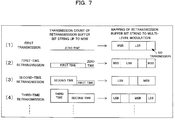
- the per-bit transmission count control section 17 preferentially maps a bit having a smaller transmission count up to present to a bit having a lower error resilience (MSB) in the transmission symbol for each retransmission processing, thereby facilitating mapping of a bit having a greater transmission count to a more error prone bit (LSB) in the transmission symbol, as schematically illustrated in FIG. 7 , for example.
- MSB error resilience
- the per-bit transmission count control section 17 functions as an obtainment means that obtains information on a per-bit transmission of a transmission bit string for every transmission to the reception apparatus 2, and a control means that controls a per-bit transmission method of the current transmission bit string based on cumulative information on the above-described transmissions up to the last transmission obtained by the obtainment means such that the per-bit transmission quality of the transmission bit string approaches evenly.
- counting the per-bit transmission count (that is, obtaining the per-bit transmission quality) can be achieved by counting the transmission count for each bit storage location (memory address) in the transmission buffer 13, for example.
- the per-bit transmission count control section 17 does not apply the above-described rule and performs normal mapping (for example, such as evenly mapping to MSBs and LSBs).
- the per-bit transmission count control section 17 preferentially maps bits having a smaller transmission count up to present to MSBs in the manner similar to those described above, which, in turn, results in facilitating mapping of bits having a greater transmission count to LSBs.
- bits having greater transmission counts may be preferentially mapped to LSBs, as being opposite to the case of the example as set forth above.
- the transmission apparatus 1 carries out retransmission processing in response to reception of a NACK from the reception apparatus 2, it is possible to achieve an improvement in the communication capacity by preferentially mapping bits having a smaller transmission count up to present in a multi-level modulation signal to MSBs since it is possible to make the per-bit signal quality (likelihood) after an HARQ synthesis to approach evenly.
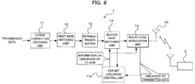
- FIG. 8 is a functional block diagram illustrating the configuration of a wireless communication system of a second embodiment.
- the wireless communication system depicted in FIG. 8 also includes a wireless the transmission apparatus 1 and a wireless reception apparatus 2.
- the wireless the transmission apparatus 1 also includes a per-bit likelihood control section 17a that obtains a per-bit likelihood as one example of information on a per-bit transmission.
- the per-bit likelihood control section (per-bit likelihood obtaining section, symbol mapping control section) 17a is adapted to, for a transmission bit string having a predetermined size that is temporarily stored in the retransmission buffer 13, obtain and cumulatively store information on a per-bit likelihood (estimated likelihood at the reception apparatus 2) from the multi-level modulation section 15 for each transmission opportunity, and to control processing of the second rate matching processing section 14 and the multi-level modulation section 15 such that a bit having a greater synthetic likelihood up to present in the present transmission is preferentially mapped to a bit having a lower likelihood (LSB).
- LSB lower likelihood
- the likelihood is information indicative of the confidence (error resilience) whether each bit is zero or one, and a higher likelihood means a higher confidence (a higher signal quality).
- the likelihood can be determined as the average of the squares of the distances from the reference point on the I-Q plane (the determination axis upon an error correction decoding at the reception apparatus 2).
- the per-bit likelihood control section 17a will carry out mapping of bits that have a higher synthetic likelihood up to present and have a higher signal quality in the present transmission to bits having a lower likelihood (LSBs).
- likelihood values described above may be determined as logarithmic likelihood values.
- the per-bit likelihood control section 17a preferentially maps bits having smaller synthetic likelihoods up to present to bits having a higher likelihood (MSBs) for each retransmission processing (transmission opportunity), thereby facilitating mapping of bits having higher synthetic likelihoods to bits having a lower likelihood (LSBs).
- the per-bit likelihood control section 17a functions as an obtainment means that obtains information on a per-bit transmission of a transmission bit string for every transmission to the reception apparatus 2, and a control means that controls a per-bit transmission method of the current transmission bit string based on cumulative information on the above-described transmissions up to the last transmission obtained by the obtainment means such that the per-bit transmission quality of the transmission bit string approaches evenly.
- the per-bit likelihood control section 17a does not apply the above-described rule and performs normal mapping. For example, bits are evenly mapped to MSBs and LSBs.
- the per-bit likelihood control section 17a preferentially maps bits having a smaller synthetic likelihood up to present to MSBs having a higher likelihood in the manner similar to those described above, which, in turn results in facilitating mapping of bits having a greater synthetic likelihood to LSBs having a smaller likelihoods.
- bits having greater synthetic likelihoods may be preferentially mapped to LSBs, as being opposite to the case of the example as set forth above.
- the transmission apparatus 1 carries out retransmission processing in response to reception of a NACK from the reception apparatus 2, it is possible to achieve an improvement in the communication capacity by preferentially mapping bits having a synthetic likelihood count up to present in a multi-level modulation signal to MSBs since it is possible to make the per-bit signal quality (likelihood) after an HARQ synthesis to approach evenly.
- the per-bit likelihood control section 17a may divide a transmission bit string in the retransmission buffer 13 into multiple groups in suitable lengths, and preferentially map bits having a smaller synthetic likelihood up to present within such a group to MSBs, as schematically illustrated in FIG. 11 , for example.
- bit groups mapped to LSBs are fixed, and bits having a smaller synthetic likelihood up to present within the remaining bit groups are preferentially mapped to MSBs.
- bit groups mapped to MSBs may be fixed.
- mapping control By performing such mapping control by means of grouping, it is possible to reduce the number of bits used for comparing magnitudes of synthetic likelihoods even when the unit (size) of transmission bit strings in the retransmission buffer 13 is increased. Accordingly, mapping control can be simplified, thereby reducing the device size, power consumption, or the like. Further advantages can be obtained by fixing bit groups to be mapped to LSBs or MSBs, as the example depicted in FIG. 11 .
- grouping as described above may be applied to the first embodiment.
- grouping may also be applied to the other wireless communication systems that will be described later.
- likelihood information that is obtained upon an error correction decoding at the reception apparatus 2 may be fed back to the per-bit likelihood control section 17a in the transmission apparatus 1.
- the transmission apparatus 1 can carry out the above-described per-bit mapping control on a transmission bit string based on likelihoods in accordance with the actual wireless propagation environment from the transmission apparatus 1 to the reception apparatus 2. Accordingly, optimization of the communication capacity can be realized which is responsive to variation in the wireless propagation environment.
- FIG. 12 is a functional block diagram illustrating the configuration of a wireless communication system which is not specifically claimed.
- the wireless communication system depicted in FIG. 12 includes an MIMO transmitter as a wireless transmission apparatus 1 and an MIMO receiver as a wireless reception apparatus 2.
- the MIMO transmitter 1 In addition to including an error correction decoding section 11, a first rate matching processing section 12, a retransmission buffer (memory) 13, and a second rate matching processing section 14 that are similar to those depicted in FIG. 6 , the MIMO transmitter 1 also includes a per-bit transmission count control section 17b that counts a per-bit transmission count as one example of information on a per-bit transmission, multiple antennas 16, a mapper 18, and a transmission antenna control information generation section 19.
- the mapper 18 includes a function that separates transmission data (a transmission bit string) that undergoes the rate matching processing by the second rate matching processing section 14, to transmission streams for the transmission antennas 16, and carries out mapping to a multi-level modulation signal (transmission symbol), such as one in the QPSK or the 16-QAM for each transmission stream.
- the per-bit transmission count control section (per-bit transmission count counting section, antenna mapping control section) 17b is adapted to, for a transmission bit string having a predetermined size that is temporarily stored in the retransmission buffer 13, counts and stores a transmission count for each transmission opportunity, and to control the second rate matching processing section 14 and the mapper 18 such that a bit having a greater transmission count up to present in the present transmission is preferentially mapped to a transmission antenna 16 (channel) exhibiting a lower transmission quality.
- the transmission quality for each transmission antenna 16 is determined (identified) based on transmission antenna quality information fed back (notified) from the MIMO receiver 2 (information indicative of which transmission antenna 16 has a higher transmission quality), for example.
- the transmission antenna quality information may be information indicative of the quality of each transmission antenna 16, or may be information indicative of the ranking of qualities. In addition, the information may not be one on all of the transmission antennas 16, but may be limited for a part of transmission antennas 16 used for transmission.
- Such transmission antenna quality information can be determined at the MIMO receiver 2 based on the received powers of known signals, such as pilot signals, which are transmitted from different transmission antennas 16 at different times from the MIMO transmitter 1, or are transmitted in parallel for each transmission antenna 16, for example.
- the per-bit transmission count control section 17b preferentially maps, for each retransmission processing (transmission opportunity), bits having a smaller transmission count up to present to a transmission antenna 16 (channel) exhibiting a higher transmission quality, as schematically illustrated in FIG. 13 , for example. This, in turn, results in facilitating mapping of bits having a greater transmission count to a transmission antenna 16 exhibiting a lower transmission quality.
- the per-bit transmission count control section 17b functions as an obtainment means that obtains information on a per-bit transmission of a transmission bit string for every transmission to the MIMO receiver 2, and a control means that controls a per-bit transmission method of the current transmission bit string based on cumulative information on the above-described transmissions up to the last transmission obtained by the obtainment means such that the per-bit transmission quality of the transmission bit string approaches evenly.
- the example depicted in FIG. 13 assumes the case in which there are two transmission antennas 16 (Tx1 and Tx2) and the transmission antenna Tx1 has a higher transmission quality than that of the transmission antenna Tx2.
- the per-bit transmission count control section 17b does not apply the above-described rule and performs normal mapping. For example, bits are evenly mapped to the transmission antennas Tx1 and Tx2.
- the per-bit transmission count control section 17b preferentially maps bits having a smaller transmission count up to present to the transmission antenna Tx1 exhibiting a higher transmission quality in the manner similar to those described above, which, in turn, results in facilitating mapping of bits having a greater transmission count to the transmission antenna Tx2 exhibiting a lower transmission quality.
- bits having greater transmission counts may be preferentially mapped to the transmission antenna Tx2 exhibiting a lower transmission quality, as being opposite to the case of the example as set forth above.
- the MIMO transmitter 1 carries out retransmission processing in response to reception of a NACK from the MIMO receiver 2, it is possible to achieve an improvement in the communication capacity by mapping bits having a smaller transmission count up to present in a multi-level modulation signal to a transmission antenna 16 exhibiting a higher transmission quality since it is possible to make the per-bit signal quality (likelihood) after an HARQ synthesis to approach evenly.
- the transmission antenna control information generation section 19 is adapted to generate information (transmission antenna control information) indicative of which transmission antenna 16 has a higher transmission quality and thus a bit is mapped to by the per-bit likelihood control section 17c (mapping method).
- the information is sent from the transmission antennas 16 to the MIMO receiver 2 as control information that is accompanied with transmission data, for example.
- the MIMO receiver 2 can carry out appropriate demapping processing, demodulation processing, decode processing on a reception signal based on the transmission antenna control information.
- the transmission antenna control information may be information indicative of the ranking of transmission qualities of the transmission antennas 16, similar to the feedback information from the MIMO receiver 2 described above.
- FIG. 14 is a functional block diagram illustrating the configuration of a further wireless communication system which is not specifically claimed.
- the wireless communication system depicted in FIG. 14 includes an MIMO transmitter as a wireless transmission apparatus 1 and an MIMO receiver as a wireless reception apparatus 2.
- the MIMO transmitter 1 In addition to including an error correction decoding section 11, a first rate matching processing section 12, a retransmission buffer (memory) 13, and a second rate matching processing section 14 that are similar to those depicted in FIG. 6 , and multiple antennas 16, the mapper 18, the transmission antenna control information generation section 19 that are similar to those depicted in FIG. 12 , the MIMO transmitter 1 also includes a per-bit likelihood control section 17c that obtains a per-bit likelihood as one example of information on a per-bit transmission.
- the per-bit likelihood control section (per-bit likelihood obtaining section, symbol mapping control section) 17c is adapted to, for a transmission bit string having a predetermined size that is temporarily stored in the retransmission buffer 13, obtain and cumulatively store information on a per-bit likelihood (estimated likelihood at the MIMO receiver 2) from the mapper 18 for each transmission opportunity, and to control the second rate matching processing section 14 and the mapper 18 such that a bit having a greater synthetic likelihood up to present in the present transmission is preferentially mapped to a transmission antenna 16 exhibiting a lower transmission quality.
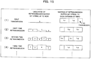
- the per-bit likelihood control section 17c preferentially maps, for each retransmission processing (transmission opportunity), bits having a synthetic likelihood up to present to a transmission antenna 16 (channel) exhibiting a higher transmission quality, as schematically illustrated in FIG. 15 , for example. This, in turn, results in facilitating mapping of bits having a greater synthetic likelihood to a transmission antenna 16 exhibiting a lower transmission quality.
- the per-bit likelihood control section 17c functions as an obtainment means that obtains information on a per-bit transmission of a transmission bit string for every transmission to the MIMO receiver 2, and a control means that controls a per-bit transmission method of the current transmission bit string based on cumulative information on the above-described transmissions up to the last transmission obtained by the obtainment means such that the per-bit transmission quality of the transmission bit string approaches evenly.
- the transmission quality for each transmission antenna 16 is also determined (identified) based on transmission antenna quality information fed back (notified) from the MIMO receiver 2 (information indicative of which transmission antenna 16 has a higher transmission quality), similar to the non-claimed previous example as described above .
- the transmission antenna quality information may be information indicative of the quality of each transmission antenna 16, or may be information indicative of the ranking of qualities. In addition, the information may not be one on all of the transmission antennas 16, but may be limited for a part of transmission antennas 16 used for transmission.
- such transmission antenna quality information can also be determined at the MIMO receiver 2 based on the received powers of known signals, such as pilot signals, which are transmitted from different transmission antennas 16 at different times from the MIMO transmitter 1, or are transmitted in parallel for each transmission antenna 16.
- the example depicted in FIG. 15 assumes the case in which there are two transmission antennas 16 (Tx1 and Tx2) and the transmission antenna Tx1 has a higher transmission quality than that of the transmission antenna Tx2 (the likelihood of the transmission antenna Tx1 is two, and the likelihood of the transmission antenna Tx2 is one).
- the per-bit likelihood control section 17c Since transmission counts up to present for all transmission bits stored in the retransmission buffer 13 are all zero upon the first transmission, the per-bit likelihood control section 17c does not apply the above-described rule and performs normal mapping. For example, bits are evenly mapped to the transmission antennas Tx1 and Tx2.
- the per-bit likelihood control section 17c preferentially maps bits having a smaller synthetic likelihood up to present to the transmission antenna Tx1 in the manner similar to those described above, which, in turn, results in facilitating mapping of bits having a greater synthetic likelihood to the transmission antenna Tx2.
- bits having greater synthetic likelihoods may be preferentially mapped to the transmission antenna Tx2 exhibiting a lower transmission quality, as being opposite to the case of the example as set forth above.
- the MIMO transmitter 1 carries out retransmission processing in response to reception of a NACK from the MIMO receiver 2, it is possible to achieve an improvement in the communication capacity by mapping bits having a smaller synthetic likelihood up to present in a multi-level modulation signal to a transmission antenna 16 exhibiting a higher transmission quality since it is possible to make the per-bit signal quality (likelihood) after an HARQ synthesis to approach evenly.
- the transmission antenna control information generation section 19 is adapted to generate information (transmission antenna control information) indicative of which transmission antenna 16 has a higher transmission quality and thus a bit is mapped to by the per-bit likelihood control section 17c (mapping method), and send the information to the reception apparatus 2, similar to the third embodiment described above.
- symbol mapping control that has been described previously with respect to the first or second embodiment may be applied to the above-described third or fourth embodiments. That is, in addition to mapping control to the transmission antennas 16, symbol mapping control to a multi-level modulation signal (transmission symbol) may be carried out. This can provide a further effect in improving the communication capacity.
- symbol mapping control to a multi-level modulation signal or mapping control to transmission antennas has been described as control on the per-bit transmission condition in the above-described examples, advantageous effects similar to those of each embodiment described above can be obtained by controlling on a per-bit transmission power.
- the transmission quality of a signal is improved with an increase in the transmission power, it is possible to achieve an improvement in the communication capacity by controlling to reduce transmission power as the transmission count or synthetic likelihood of a bit is increased (controlling to increase the transmission power as the transmission count or synthetic likelihood of a bit is decreased), thereby making the per-bit transmission quality to approach evenly.
Description
- The present invention relates to a transmission method and a transmission apparatus. The present invention is suitable for using in a wireless communication system that performs retransmission control on transmission data, for example.
- Multi-level modulation schemes, such as one in the QPSK or the 16-QAM, are known as one type of modulation schemes for the wireless communication technique. In multi-level modulation schemes, a transmission bit string that is encoded using an error correction code, such as a turbo code, is mapped to a multi-level modulation signal (symbol). In the case of the 16-QAM, since one symbol is made up of four bits, a transmission bit string is mapped to one of the four bits.
- In addition, the HARQ is known as one of elemental techniques for wireless communication techniques, such as the High Speed Downlink Packet Access (HSDPA) (see Non-Patent
Document 1 that is listed below, for example) . The HARQ is the technique in which data, a reception of which failed, is retained, instead of discarding it at the receiving party, and the data is decoded (error correction decoded) together with other data sent from the transmitting party. In this manner, the gain in error correction code is increased and thus reducing the retransmission count even when an error occurs, by effectively utilizing data that has been received. - Furthermore, the MIMO is known as one technique for wireless communications. The MIMO is a technique to improve the transmission rate without requiring an increase in the frequency band, in which multiple antennas are used for both transmission and reception, dependent data streams are sent from multiple antennas of the transmitter, and multiple signals (data stream) that are mixed on the transmission path (channel) are separated from each other from signals received by each reception antenna of the receiver.
- Note that
Patent Document 1 that is listed below describes that the error resilience of code division blocks are deviated caused by the signal point arrangement of multi-level modulation signals and the uniformity in the quality among the blocks may be reduced. Thus, it is possible to make the error resilience among blocks to approach evenly by manipulating (controlling) a transmission bit string such that the occupying rate of organizational bit (or redundant bit) included in each block approaches evenly. - Patent Document 1: Japanese Laid-Open Patent Application No.
2005-229319 - Non-Patent Document 1: 3GPP TS 25.212 V7.4.0 (2007-03)
-
US 2004/199846 discloses a sequence converting section that interchanges high-order bits where an error does not easily occur and low-order bits where an error easily occurs, that are used by an M-ary modulating section for each retransmission. The M-ary modulating section performs M-ary modulation using the high-order bits and low-order bits interchanged for each retransmission. An M-ary modulated symbol is interleaved with an interleave pattern being different for each retransmission, and multicarrier transmitted via an OFDM transmitting section. -
WO 03/043260 - An object of the present invention is to make the per-bit reception quality of a transmission bit string to approach evenly.
- In addition, another object of the present invention is to improve the wireless communication characteristic (for example, the communication capacity).
- Note that it is an object of the present invention to provide advantages and effects that can be obtained by the above-described best modes to implement the above-described invention described below but cannot be obtained with conventional techniques.
- In order to achieve the above-described objects, the present specification discloses transmission methods and transmission apparatuses as defined in the claims.
approaches evenly based on cumulative information on the transmissions up to the last transmission. -
- (2) Here, the transmission apparatus may be a transmission apparatus that sends the transmission bit string to the reception apparatus by mapping the transmission bit string to a transmission symbol of multi-level modulation, the information on the transmission may be a per-bit transmission count, and the controlling on the transmission condition may be controlling such that a bit having a higher value of the transmission count up to the last transmission among a current transmission bit string is mapped to a bit having a lower error resilience in the transmission symbol of multi-level modulation.
- (3) In addition, the transmission apparatus may be a transmission apparatus that sends the transmission bit string to the reception apparatus by mapping the transmission bit string to a transmission symbol of multi-level modulation, the information on the transmission may be a per-bit likelihood, and the controlling on the transmission condition may be controlling such that a bit having a higher value of a synthetic likelihood up to the last transmission among a current transmission bit string is mapped to a bit having a lower error resilience in the transmission symbol.
- (4) Furthermore, the transmission apparatus may be a transmission apparatus that maps the transmission bit string to one of a plurality of transmission antennas and sends the transmission bit string to the reception apparatus, the information on the transmission may be a per-bit transmission count, and the controlling on the transmission condition may be controlling such that a bit having a higher value of the transmission count up to the last transmission among a current transmission bit string is mapped to an antenna exhibiting a lower transmission quality.
- (5) In addition, the transmission apparatus may be a transmission apparatus that maps the transmission bit string to one of a plurality of transmission antennas and sends the transmission bit string to the reception apparatus, the information on the transmission may be a per-bit likelihood, and the controlling on the transmission condition may be controlling such that a bit having a higher value of a synthetic likelihood up to the last transmission among a current transmission bit string is mapped to an antenna exhibiting a lower transmission quality.
- (6) Furthermore, the method may further include identifying the transmission antenna exhibiting a lower transmission quality based on quality information that is measured at the reception apparatus and notified from the reception apparatus.
- (7) In addition, the method may further include, by the transmission apparatus, notifying the reception apparatus of information on the transmission antenna that is mapped by the controlling.
- (8) In addition, a transmission apparatus disclosed herein is a transmission apparatus that transmits, to a reception apparatus, a transmission bit string containing a bit that is sent, the apparatus including: an obtainment means that obtains, for each transmission to the reception apparatus, information on a per-bit transmission of a transmission bit string; and a control means that controls a per-bit transmission condition for a current transmission bit string such that a per-bit transmission quality of the transmission bit string approaches evenly based on cumulative information on the transmissions up to the last transmission obtained by the obtainment means.
- (9) Here, the transmission apparatus may further include a multi-level modulation means that sends the transmission bit string to the reception apparatus by mapping the transmission bit string to a transmission symbol of multi-level modulation, wherein the obtainment means may include a per-bit transmission count counting section that counts a per-bit transmission count as the information on transmission, and the control means may include a symbol mapping control section that controls the multi-level modulation means, as control on the transmission condition such that, a bit having a higher value of the transmission count up to the last transmission among a current transmission bit string is mapped to a bit having a lower error resilience in the transmission symbol of multi-level modulation based on a count result from per-bit transmission count counting section.
- (10) In addition, the transmission apparatus may further include a multi-level modulation means that sends the transmission bit string to the reception apparatus by mapping the transmission bit string to a transmission symbol of multi-level modulation, wherein the obtainment means may include a per-bit likelihood obtaining section that determines per-bit likelihood as information on the transmission, and the control means may include a symbol mapping control section that controls the multi-level modulation means, as control on the transmission condition such that, a bit having a higher value of a synthetic likelihood up to the last transmission among a current transmission bit string is mapped to a bit having a lower error resilience in the transmission symbol for based on a likelihood obtained by per-bit likelihood obtaining section.
- (11) Furthermore, the transmission apparatus may further include a mapping means that maps the transmission bit string to one of a plurality of transmission antennas and sends the transmission bit string to the reception apparatus, wherein the obtainment means may include a per-bit transmission count counting section that counts a per-bit transmission count as the information on transmission, and the control means may include an antenna mapping control section that controls the mapping means, as control on the transmission condition such that, a bit having a higher value of the transmission count up to the last transmission among a current transmission bit string is mapped to an antenna exhibiting a lower transmission quality based on a count result from the per-bit transmission count counting section.
- (12) In addition, the transmission apparatus may further include a mapping means that maps the transmission bit string to one of a plurality of transmission antennas and sends the transmission bit string to the reception apparatus, wherein the control means may include a per-bit likelihood obtaining section that determines a per-bit likelihood as information on the transmission, the control means may include an antenna mapping control section that controls the mapping means, as control on the transmission condition such that, a bit having a higher value of a synthetic likelihood up to the last transmission among a current transmission bit string is mapped to an antenna exhibiting a lower transmission quality based on a likelihood obtained by the per-bit likelihood obtaining section.
- (13) Furthermore, the antenna mapping control section may identify the transmission antenna that has a lower transmission quality based on quality information on each of the transmission antennas that is measured at the reception apparatus and notified from the reception apparatus, and controls the mapping based on the identified information.
- (14) In addition, the transmission apparatus may further include a transmission antenna information transmission means that notify the reception apparatus of information on a transmission antenna that is mapped.
- According to the technique as set forth above, it is possible to make the per-bit reception quality of a transmission bit string to approach evenly.
- In addition, it is also possible to improve the wireless communication characteristic (for example, the communication capacity).
-
-
FIG. 1 is a schematic diagram illustrating there is no rule for mapping of bits with different transmission counts to multi-level modulation signals in a retransmission buffer; -
FIG. 2 is a graph illustrating one example of the relationship between the signal quality and the communication capacity; -
FIG. 3 is a schematic diagram illustrating how mapping of bits having greater transmission counts to lower quality bits (LSBs) can improve the communication capacity; -
FIG. 4 is a diagram illustrating an example of the signal point arrangement in the 16-QAM that is one of multi-level modulation schemes; -
FIG. 5 is a graph illustrating one example of the relationship between the communication capacity and the reception quality by comparing between mapping of bits having greater transmission counts to lower quality bits (LSBs) and mapping to higher quality bits (MSBs); -
FIG. 6 is a functional block diagram illustrating the configuration of a wireless communication system of a first embodiment; -
FIG. 7 is a schematic diagram illustrating a transmission method (mapping method) in the wireless communication system depicted inFIG. 6 ; -
FIG. 8 is a functional block diagram illustrating the configuration of a wireless communication system of a second embodiment; -
FIG. 9 is a schematic diagram illustrating a transmission method (mapping method) in the wireless communication system depicted inFIG. 8 ; -
FIG. 10 is a schematic diagram illustrating another transmission method (mapping method) in the wireless communication system depicted inFIG. 8 ; -
FIG. 11 is a diagram illustrating per-bit likelihoods;FIG. 12 is a functional block diagram illustrating the configuration of a wireless communication system, which is not specifically claimed; -
FIG. 13 is a schematic diagram illustrating a transmission method (mapping method) in the wireless communication system depicted inFIG. 12 ; -
FIG. 14 is a functional block diagram illustrating the configuration of a further wireless communication system, which is not specifically claimed; and -
FIG. 15 is a schematic diagram illustrating a transmission method (mapping method) in the wireless communication system depicted inFIG. 14 . -
- 1 WIRELESS TRANSMISSION APPARATUS (MIMO TRANSMITTER)
- 11 ERROR CORRECTION DECODING SECTION
- 12 FIRST RATE MATCHING PROCESSING SECTION
- 13 RETRANSMISSION BUFFER
- 14 SECOND RATE MATCHING PROCESSING SECTION
- 15 MULTI-LEVEL MODULATION SECTION
- 16 TRANSMISSION ANTENNA
- 17 BIT-WISE TRANSMISSION COUNT CONTROL SECTION
- 17a BIT-WISE LIKELIHOOD CONTROL SECTION
- 17b BIT-WISE TRANSMISSION COUNT CONTROL SECTION
- 17c BIT-WISE LIKELIHOOD CONTROL SECTION
- 18 MAPPER
- 19 TRANSMISSION ANTENNA CONTROL INFORMATION GENERATION SECTION
- 2 WIRELESS RECEPTION APPARATUS (MIMO RECEIVER)
- Hereinafter, embodiments of the present invention will be described with reference drawings. It is understood that the present invention is not limited to the above-described embodiments that will be illustrated below, and various modifications may be made without departing from the present invention. For example, any combinations of embodiments other than those listed below.
- In this example, mapping of a transmission bit string to a symbol (signal point) of multi-level modulation, such as one in the QPSK or the 16-QAM, allocation of a transmission bit string to transmission antennas of the MIMO, and the signal quality (reception quality) of each bit that is dependent on mapping destinations (signal point locations, antennas to be allocated) are considered. Note that, hereinafter, allocating a transmission bit string to one of transmission antennas is also referred to as "mapping."
- For example, when an error correction encoded transmission bit string is sent by carrying out rate matching (puncture processing or repetition processing) such that the string is accommodated within a predetermined transmission frame and thereafter mapping to a multi-level modulation signal (symbol), such as one in the 16-QAM, transmission counts of each bit within the transmission bit string may deviate if retransmission control (for example, retransmission control based on the HARQ) is carried out.
- That is, in systems, such as HSDPA systems employing the adaptive modulation and coding (AMC) scheme, since the number of bits included in a transmission bit string is not always constant. Thus, when focusing on the first transmission and the first-time retransmission, when the transmission bit string is mapped to a symbol of a multi-level modulation as schematically illustrated in
FIG. 1 , for example, some bits may be transmitted in both the first transmission and the first-time retransmission, but other bits may be processed differently (such bits are transmitted in the first transmission and/or the first-time retransmission). - There has been no way figured out how such a transmission bit string containing bits with different transmission counts is to be mapped to a symbol of a multi-level modulation, or how bits with different transmission counts to be allocated to which transmission antenna for the MIMO communication.
- For this reason, there may be a deviation (variation) in the per-bit reception quality (likelihood) as a result of an HARQ synthesis at the receiving party, and thus the wireless communication characteristic (for example, communication capacity) may not be always optimized.
- In such an example, the reception characteristic is improved by applying a rule of mapping by using the following characteristics.
- The relationship between the communication capacity versus the signal quality (for example, the signal noise ratio (SNR), likelihood, or the like) is such that the slope (the magnitude of an improvement in the communication capacity) is increased when the signal quality (reception quality) is lower, meaning that the communication capacity can be more easily improved with a smaller change in the signal quality, as illustrated in
FIG. 2 . On the other hand, since the slope is decreased when the signal quality becomes somewhat high, the rate of an improvement in the communication capacity is reduced with respect to an improvement in the signal quality. Note that the characteristic depicted inFIG. 2 corresponds to the Shannon's communication capacity, and is used for approximation of error rates in the following reference. - Reference: K. Brueninghaus et al., "Link performance models for system level simulations of broadband radio access systems", in Proc. PIMRC 2005
- Accordingly, it is possible to improve (increase) the communication capacity by sending a bit in a lower signal quality twice (in the first transmission and the first-time retransmission), for example.
- For example, as schematically illustrated in
FIG. 3 (1), a case is assumed in which a transmission bit sequence of a predetermined bit length is stored in a transmission buffer and bits that are to be sent twice (in the first transmission and the first-time retransmission) (hereinafter, referred to as "overlapped bits") are present in the transmission bit sequence. - In addition, it is assumed that the transmission bit sequence is (mapped and) sent by relating the sequence to a transmission symbol (signal point) of a multi-level modulation (for example, the 16-QAM). The transmission symbol (signal point) can be represented by values of the I-axis (bits of the MSB and the LSB) and values of the Q-axis (bits of the MSB and the LSB) on the complex plane of the I channel and the Q channel (the I-Q plane).
- Here, on this complex plane, focusing on bits that are mapped to the outer signals point (in the farther locations on the I-axis and the Q-axis), an MSB does not become an error (i.e., remains zero or one) even when such a signal point is erroneously mapped to the adjacent signal point. On the other hand, an LSB may become an error (i.e. , zero is inverted to one, or one is inverted to zero) when the LSB becomes an error to the adjacent signal point when mapped to any of the signal points. That is, it can be said that MSBs are relatively more error resilient compared to LSBs in this case because of the characteristic of the mapping destination.
- Accordingly, it can be said that bits mapped to MSBs are more error resilient, and thus have higher signal quality, compared to bits mapped to LSBs.
- In this case, comparing between the case in which, as schematically illustrated in
FIG. 3 (3), a transmission bit string is sent by mapping bits overlapping in the first transmission and the first-time retransmission to bits exhibiting a signal quality higher than others (more error resilient bits) (MSBs) in a transmission symbol and mapping bits other than the overlapping bit in the transmission bit string to bits exhibiting a signal quality lower than others (more error prone bits) (LSBs) in a transmission symbol, and the opposite case in which, as schematically illustrated inFIG. 3 (2), a transmission bit string is sent by mapping bits overlapping in the first transmission and the first-time retransmission to more error prone bits (LSBs) and mapping bits other than the overlapping bit in the transmission bit string to more error resilient bits (MSBs), the two cases are comparable in terms of the reception quality. That is, inFIG. 3 (2) and (3) , when expressing the reception quality per transmission bit (error resilience) in terms of area, that is, the area is increased as the quality increases (MSBs are wider than LSBs), the two cases have comparative areas. - However, in terms of the communication capacity, when comparing between the case in which overlapping bits are sent by mapping both to LSBs as schematically illustrated in
FIG. 3 (4), and the case in which overlapping bits are sent by mapping both to MSBs as schematically illustrated inFIG. 3 (5), the communication capacity is improved (increased) when the overlapping bit are mapped to LSBs (example ofFIG. 3 (4)) because of the characteristic described above with reference toFIG. 2 in that the communication capacity is greatly improved with a smaller change in the reception quality as the signal quality is reduced. That is, inFIG. 3 (4) and (5) , when expressing the communication capacity per transmission bit in terms of area, the example depicted inFIG. 3 (4) has a wider area. - As described above, a restriction (rule) for mapping the common bits to LSBs (relatively more error prone bits) of the 16-QAM in both the first transmission and the retransmission in the first time is applied, in other words, bits having a greater transmission count are preferentially mapped to LSBs.
- This can make the per-bit signal quality (likelihood) to approach to the uniform level as a result of the HARQ synthesis at the receiving party (see
FIG. 3 (2)) since bits exhibiting lower signal qualities are preferentially retransmitted in a multi-level modulation signal. As a result, it is possible to increase the communication capacity. - For example, as depicted in
FIG. 5 , when comparing the communication capacity in the first-time retransmission between the case in which the common bits are mapped to LSBs in both the first transmission and the retransmission in the first time (see reference numeral 100) and the case in which the common bits are mapped to MSBs (see reference numeral 200), the communication capacity is increased in the former case than in the latter case. - Note that, when the definition of values of the I-axis and the Q-axis (MSBs and LSBs) is different from the above-described definition of the example depicted in
FIG. 4 , error prone bits and more error resilient bits in a bit string mapped to a transmission symbol are varied. In such case, it is possible to achieve an improvement in the communication capacity by preferentially mapping bits having a greater transmission count to more error prone bits in the transmission symbol. - Furthermore, in systems that employ multiple antennas, such as MIMO communication systems, it is also possible to achieve an improvement in the communication capacity by sending by preferentially mapping bits having a greater transmission count (or bits having a lower estimated likelihood) to transmission antennas exhibiting a lower transmission quality.
- From the foregoing description, it can be understood that it is possible to achieve an improvement in the communication capacity by obtaining, by the transmitting party, information on the transmission quality, such as the per-bit transmission count or likelihood, of a transmission bit string for every transmission to the receiving party, and controlling a per-bit transmission condition for a current transmission bit string (mapping method to a multi-level modulation signal or a transmission antenna) such that the per-bit reception quality of a transmission bit string approaches evenly based on cumulative information on such transmission quality up to the last transmission.
- Hereafter, embodiments will be described in detail with reference to a first embodiment in which the per-bit transmission count is obtained (counted) to control the mapping method to a multi-level modulation signal, a second embodiment in which the per-bit likelihood is obtained to multi-level modulation signal to control the mapping method to a multi-level modulation signal, a third example in which the per-bit transmission count is obtained to control the mapping method to a transmission antenna of the MIMO, and a fourth embodiment in which the per-bit likelihood is obtained to control the mapping method to a transmission antenna of the MIMO.
-
FIG. 6 is a functional block diagram illustrating the configuration of a wireless communication system of a first embodiment. The wireless communication system depicted inFIG. 6 includes awireless transmission apparatus 1 and awireless reception apparatus 2. Thewireless transmission apparatus 1 can be applied to a transmission system of a wireless base station (BS) or a transmission system of wireless terminal (UE), and thewireless reception apparatus 2 can be applied to a reception system of the BS or a reception system of the UE, for example (this is applicable to the following embodiments). - The wireless transmission apparatus (hereinafter, simply referred to as "transmission apparatus") 1 includes an error
correction decoding section 11, a first ratematching processing section 12, a retransmission buffer (memory) 13, a second rate matchingprocessing section 14, amulti-level modulation section 15, atransmission antenna 16, and a per-bit transmissioncount control section 17 that counts a per-bit transmission count that is one example of information on per-bit transmission. - Here, the error
correction decoding section 11 is adapted to perform error correction encoding on transmission data addressed to thewireless reception apparatus 2. An example of the error correction encoding includes turbo encoding. The transmission data encoded by the errorcorrection decoding section 11 is input to the first ratematching processing section 12. - The first rate
matching processing section 12 is adapted to perform first rate matching processing (puncture processing for reducing the bits or repetition processing by repeating bits) on the transmission data to which the above-described error correction encoding is executed so that the transmission data is stored within a predetermined region in theretransmission buffer 13. The transmission data on which the rate matching processing is performed by the first ratematching processing section 12 is input to theretransmission buffer 13. - The
retransmission buffer 13 is adapted to store the transmission data (transmission bit string) that undergoes the above-described rate matching processing for retransmission. In response to receiving an NACK signal from areception apparatus 2 indicative of a reception error, the stored transmission data is read according to a control by a retransmission control section (not shown) and is input into the second rate matchingprocessing section 14. - The second rate matching
processing section 14 is adapted to perform second rate matching processing (puncture processing for cutting out the bits or repetition processing by repeating bits) on the transmission data input from theretransmission buffer 13 so as to adjust the transmission data into a data length (bit count) so that the transmission data is accommodated within a predetermined region in a wireless frame. By means of such two-stage rate matching processing, the encoding rate of the transmission data can be flexibly adjusted. The transmission data that undergoes the rate matching processing by the second rate matchingprocessing section 14 is input to themulti-level modulation section 15. - The
multi-level modulation section 15 is adapted to map the transmission data (transmission bit string) that undergoes the above-described second rate matching processing to a multi-level modulation signal (symbol), such the one of as 16-QAM, thereby amplitude phase keying. In the case of the 16-QAM, one symbol is made of four bits, which results in the signal point arrangement or bit arrangement illustrated inFIG. 4 . The multi-level modulation signal obtained by themulti-level modulation section 15 is input into thetransmission antenna 16. - The
transmission antenna 16 is adapted to send the signal (multi-level modulation signal) that undergoes the above-described modulation by themulti-level modulation section 15 to the wireless reception apparatus (hereinafter, simply referred to as "reception apparatus") 2 as a wireless signal (wireless frame). Note that, inFIG. 6 , a DA converter that DA-converts a transmission bit string, a frequency converter that performs frequency conversion on a multi-level modulation signal into a wireless signal (upconversion), a power amplifier that converts a multi-level modulation signal into a predetermined transmission power, or the like, are omitted from the illustration. This also applies to the second or later embodiments. - The per-bit transmission count control section (per-bit transmission count counting section, symbol mapping control section) 17 is adapted to, for a transmission bit string having a predetermined size that is temporarily stored in the
retransmission buffer 13, counts and stores information on per-bit transmissions (transmission count) for each transmission opportunity, and to control processing of the second rate matchingprocessing section 14 and themulti-level modulation section 15 such that a bit having a greater transmission count up to present in the present transmission is preferentially mapped to a more error prone bit (LSB) in a transmission symbol. - That is, the per-bit transmission
count control section 17 preferentially maps a bit having a smaller transmission count up to present to a bit having a lower error resilience (MSB) in the transmission symbol for each retransmission processing, thereby facilitating mapping of a bit having a greater transmission count to a more error prone bit (LSB) in the transmission symbol, as schematically illustrated inFIG. 7 , for example. - In other words, it is facilitated that a bit having a smaller transmission count up to present is mapped such that the transmission quality is improved, and a bit having a greater transmission count up to present is mapped such that the transmission quality is reduced.
- This is equivalent to controlling symbol mapping of multi-level modulation such that the per-bit signal quality (likelihood) of an HARQ-synthesized result using the above-described transmission bit string received by the
reception apparatus 2 approaches evenly. - Thus, it can be regarded that the per-bit transmission
count control section 17 functions as an obtainment means that obtains information on a per-bit transmission of a transmission bit string for every transmission to thereception apparatus 2, and a control means that controls a per-bit transmission method of the current transmission bit string based on cumulative information on the above-described transmissions up to the last transmission obtained by the obtainment means such that the per-bit transmission quality of the transmission bit string approaches evenly. - Note that counting the per-bit transmission count (that is, obtaining the per-bit transmission quality) can be achieved by counting the transmission count for each bit storage location (memory address) in the
transmission buffer 13, for example. - In the example depicted in
FIG. 7 , (1) since the transmission counts up to present for all transmission bits stored in theretransmission buffer 13 are all zero upon the first transmission, the per-bit transmissioncount control section 17 does not apply the above-described rule and performs normal mapping (for example, such as evenly mapping to MSBs and LSBs). - (2) Upon the first-time retransmission thereafter, the per-bit transmission
count control section 17 preferentially maps, in the transmission bit string, from bits having a transmission count up to present of zero to one of MSBs of a predetermined bit count. If there are any bits having the same transmission count which cannot be mapped to MSBs, such bits are mapped to LSBs. Bits (retransmission bits) having a transmission count of one are mapped to MSBs if there is any remaining MSBs; otherwise, the bits that cannot be mapped to MSBs are mapped to LSBs. If there is no remaining MSB, bits having a transmission count up to present of one is all mapped to LSBs. - (3) Upon the second retransmission, the per-bit transmission
count control section 17 preferentially maps, in the transmission bit string, bits having a smaller transmission count up to present (one) to MSBs. If there are any bits having the same transmission count which cannot be mapped to MSBs, such bits are mapped to LSBs. Bits having a greater transmission count of two are mapped to MSBs when there is any remaining MSB, and the bits that cannot be mapped to MSBs are mapped to LSBs. If there is no remaining MSB, bits having a transmission count up to present of two are all mapped to LSBs. - (4) Upon the third retransmission, the per-bit transmission
count control section 17 preferentially maps, in the transmission bit string, bits having a transmission count up to present of two to MSBs. If there are any bits having the same transmission count which cannot be mapped to MSBs, such bits are mapped to LSBs. Bits having a greater transmission count of three are mapped to MSBs when there is any remaining MSB, and the bits that cannot be mapped to MSBs are mapped to LSBs. If there is no remaining MSB, bits having a transmission count of three are all mapped to LSBs. - Thereafter, the per-bit transmission
count control section 17 preferentially maps bits having a smaller transmission count up to present to MSBs in the manner similar to those described above, which, in turn, results in facilitating mapping of bits having a greater transmission count to LSBs. Note that bits having greater transmission counts may be preferentially mapped to LSBs, as being opposite to the case of the example as set forth above. - As described above, when the
transmission apparatus 1 carries out retransmission processing in response to reception of a NACK from thereception apparatus 2, it is possible to achieve an improvement in the communication capacity by preferentially mapping bits having a smaller transmission count up to present in a multi-level modulation signal to MSBs since it is possible to make the per-bit signal quality (likelihood) after an HARQ synthesis to approach evenly. - Note that another rule may be adapted in which the same transmission bit is arranged in an LSB and is sent in successive transmissions (the Nth transmission, the N+1th transmission).
-
FIG. 8 is a functional block diagram illustrating the configuration of a wireless communication system of a second embodiment. The wireless communication system depicted inFIG. 8 also includes a wireless thetransmission apparatus 1 and awireless reception apparatus 2. - In addition to including an error
correction decoding section 11, a first ratematching processing section 12, a retransmission buffer (memory) 13, a second rate matchingprocessing section 14, amulti-level modulation section 15, and atransmission antenna 16 that are similar to those depicted inFIG. 6 , the wireless thetransmission apparatus 1 also includes a per-bitlikelihood control section 17a that obtains a per-bit likelihood as one example of information on a per-bit transmission. - Here, the per-bit likelihood control section (per-bit likelihood obtaining section, symbol mapping control section) 17a is adapted to, for a transmission bit string having a predetermined size that is temporarily stored in the
retransmission buffer 13, obtain and cumulatively store information on a per-bit likelihood (estimated likelihood at the reception apparatus 2) from themulti-level modulation section 15 for each transmission opportunity, and to control processing of the second rate matchingprocessing section 14 and themulti-level modulation section 15 such that a bit having a greater synthetic likelihood up to present in the present transmission is preferentially mapped to a bit having a lower likelihood (LSB). - The likelihood is information indicative of the confidence (error resilience) whether each bit is zero or one, and a higher likelihood means a higher confidence (a higher signal quality). For example, in the case of the 16-QAM, as depicted in as
FIG. 10 , the likelihood can be determined as the average of the squares of the distances from the reference point on the I-Q plane (the determination axis upon an error correction decoding at the reception apparatus 2). In the example ofFIG. 10 , the likelihood of MSBs is (32 + 12 + 12 + 32) / 4 = 5, and the likelihood of LSBs is (12 + 12 + 12 + 12) / 4 = 1 when the signal point arrangement inFIG. 4 is assumed. It can be considered that MSBs have a higher likelihood and are more error resilient (bits exhibiting a higher signal quality) since MSBs are farther from the reference point. - Accordingly, the per-bit
likelihood control section 17a will carry out mapping of bits that have a higher synthetic likelihood up to present and have a higher signal quality in the present transmission to bits having a lower likelihood (LSBs). Note that likelihood values described above may be determined as logarithmic likelihood values. - That is, as schematically illustrated in
FIG. 9 , for example, the per-bitlikelihood control section 17a preferentially maps bits having smaller synthetic likelihoods up to present to bits having a higher likelihood (MSBs) for each retransmission processing (transmission opportunity), thereby facilitating mapping of bits having higher synthetic likelihoods to bits having a lower likelihood (LSBs). - In other words, it is facilitated that a bit having a smaller synthetic likelihood up to present is mapped such that the transmission quality is improved, and a bit having a greater synthetic likelihood up to present is mapped such that the transmission quality is reduced.
- This is equivalent to controlling symbol mapping of multi-level modulation such that the per-bit estimated likelihood (reception quality) of an HARQ-synthesized result using the above-described transmission bit string received by the
reception apparatus 2 approaches evenly. - Thus, it can be regarded that the per-bit
likelihood control section 17a functions as an obtainment means that obtains information on a per-bit transmission of a transmission bit string for every transmission to thereception apparatus 2, and a control means that controls a per-bit transmission method of the current transmission bit string based on cumulative information on the above-described transmissions up to the last transmission obtained by the obtainment means such that the per-bit transmission quality of the transmission bit string approaches evenly. - In the example depicted in
FIG. 9 , (1) since the transmission counts up to present for all transmission bits stored in theretransmission buffer 13 are all zero upon the first transmission, the per-bitlikelihood control section 17a does not apply the above-described rule and performs normal mapping. For example, bits are evenly mapped to MSBs and LSBs. - (2) Upon the first-time retransmission thereafter, the per-bit
likelihood control section 17a preferentially maps, in the transmission bit string, from bits having a synthetic likelihood up to present of zero to one of MSBs of a predetermined bit count. If there is any bits having the same synthetic likelihood which cannot be mapped to MSBs, the bits are mapped to LSBs. Bits having a synthetic likelihood up to present of one are mapped to MSBs if there is any remaining MSBs; otherwise, the bits that cannot be mapped to MSBs are mapped to LSBs. Bits having a synthetic likelihood up to present of five are mapped to MSBs if there is any remaining MSBs; otherwise, the bits that cannot be mapped to MSBs are mapped to LSBs. If there is no remaining MSB, bits having a greater synthetic likelihood up to present (one or five) is all mapped to LSBs. - (3) Upon the second retransmission, the per-bit
likelihood control section 17a preferentially maps, in the transmission bit string, bits having a synthetic likelihood up to present of two to MSBs. If there is any bits having the same synthetic likelihood which cannot be mapped to MSBs, the bits are mapped to LSBs. Bits having a synthetic likelihood up to present of greater than two (five or six) are mapped to MSBs if there is any remaining MSBs; otherwise, the bits that cannot be mapped to MSBs are mapped to LSBs. If there is no remaining MSB, bits having a greater synthetic likelihood up to present of five or six is all mapped to LSBs. - (4) Upon the third retransmission, the per-bit
likelihood control section 17a preferentially maps, in the transmission bit string, bits having a synthetic likelihood up to present of six to MSBs. If there is any bits having the same synthetic likelihood which cannot be mapped to MSBs, the bits are mapped to LSBs. Bits having a synthetic likelihood up to present of greater than two (seven or ten) are mapped to MSBs if there is any remaining MSBs; otherwise, the bits that cannot be mapped to MSBs are mapped to LSBs. If there is no remaining MSB, bits having a greater synthetic likelihood up to present of seven or ten is all mapped to LSBs. - Thereafter, the per-bit
likelihood control section 17a preferentially maps bits having a smaller synthetic likelihood up to present to MSBs having a higher likelihood in the manner similar to those described above, which, in turn results in facilitating mapping of bits having a greater synthetic likelihood to LSBs having a smaller likelihoods. Note that bits having greater synthetic likelihoods may be preferentially mapped to LSBs, as being opposite to the case of the example as set forth above. - As described above, when the
transmission apparatus 1 carries out retransmission processing in response to reception of a NACK from thereception apparatus 2, it is possible to achieve an improvement in the communication capacity by preferentially mapping bits having a synthetic likelihood count up to present in a multi-level modulation signal to MSBs since it is possible to make the per-bit signal quality (likelihood) after an HARQ synthesis to approach evenly. - Note that the per-bit
likelihood control section 17a may divide a transmission bit string in theretransmission buffer 13 into multiple groups in suitable lengths, and preferentially map bits having a smaller synthetic likelihood up to present within such a group to MSBs, as schematically illustrated inFIG. 11 , for example. In the example inFIG. 11 , bit groups mapped to LSBs are fixed, and bits having a smaller synthetic likelihood up to present within the remaining bit groups are preferentially mapped to MSBs. Note that bit groups mapped to MSBs may be fixed. - By performing such mapping control by means of grouping, it is possible to reduce the number of bits used for comparing magnitudes of synthetic likelihoods even when the unit (size) of transmission bit strings in the
retransmission buffer 13 is increased. Accordingly, mapping control can be simplified, thereby reducing the device size, power consumption, or the like. Further advantages can be obtained by fixing bit groups to be mapped to LSBs or MSBs, as the example depicted inFIG. 11 . - Note that grouping as described above may be applied to the first embodiment. In addition, grouping may also be applied to the other wireless communication systems that will be described later.
- In addition, for information on a per-bit likelihood, likelihood information that is obtained upon an error correction decoding at the
reception apparatus 2 may be fed back to the per-bitlikelihood control section 17a in thetransmission apparatus 1. - In this case, the
transmission apparatus 1 can carry out the above-described per-bit mapping control on a transmission bit string based on likelihoods in accordance with the actual wireless propagation environment from thetransmission apparatus 1 to thereception apparatus 2. Accordingly, optimization of the communication capacity can be realized which is responsive to variation in the wireless propagation environment. -
FIG. 12 is a functional block diagram illustrating the configuration of a wireless communication system which is not specifically claimed. The wireless communication system depicted inFIG. 12 includes an MIMO transmitter as awireless transmission apparatus 1 and an MIMO receiver as awireless reception apparatus 2. - In addition to including an error
correction decoding section 11, a first ratematching processing section 12, a retransmission buffer (memory) 13, and a second rate matchingprocessing section 14 that are similar to those depicted inFIG. 6 , theMIMO transmitter 1 also includes a per-bit transmissioncount control section 17b that counts a per-bit transmission count as one example of information on a per-bit transmission,multiple antennas 16, amapper 18, and a transmission antenna controlinformation generation section 19. - Here, the
mapper 18 includes a function that separates transmission data (a transmission bit string) that undergoes the rate matching processing by the second rate matchingprocessing section 14, to transmission streams for thetransmission antennas 16, and carries out mapping to a multi-level modulation signal (transmission symbol), such as one in the QPSK or the 16-QAM for each transmission stream. - The per-bit transmission count control section (per-bit transmission count counting section, antenna mapping control section) 17b is adapted to, for a transmission bit string having a predetermined size that is temporarily stored in the
retransmission buffer 13, counts and stores a transmission count for each transmission opportunity, and to control the second rate matchingprocessing section 14 and themapper 18 such that a bit having a greater transmission count up to present in the present transmission is preferentially mapped to a transmission antenna 16 (channel) exhibiting a lower transmission quality. - The transmission quality for each transmission antenna 16 (channel) is determined (identified) based on transmission antenna quality information fed back (notified) from the MIMO receiver 2 (information indicative of which
transmission antenna 16 has a higher transmission quality), for example. The transmission antenna quality information may be information indicative of the quality of eachtransmission antenna 16, or may be information indicative of the ranking of qualities. In addition, the information may not be one on all of thetransmission antennas 16, but may be limited for a part oftransmission antennas 16 used for transmission. - Such transmission antenna quality information can be determined at the
MIMO receiver 2 based on the received powers of known signals, such as pilot signals, which are transmitted fromdifferent transmission antennas 16 at different times from theMIMO transmitter 1, or are transmitted in parallel for eachtransmission antenna 16, for example. - In addition, the per-bit transmission
count control section 17b preferentially maps, for each retransmission processing (transmission opportunity), bits having a smaller transmission count up to present to a transmission antenna 16 (channel) exhibiting a higher transmission quality, as schematically illustrated inFIG. 13 , for example. This, in turn, results in facilitating mapping of bits having a greater transmission count to atransmission antenna 16 exhibiting a lower transmission quality. - In other words, it is facilitated that a bit having a smaller transmission count up to present is mapped such that the transmission quality is improved, and a bit having a greater transmission count up to present is mapped such that the transmission quality is reduced.
- This is equivalent to controlling symbol mapping to the transmission antennas 16 (channels) such that the per-bit estimated likelihood (reception quality) of an HARQ-synthesized result using the above-described transmission bit string received by the
MIMO receiver 2 approaches evenly. - Thus, it can be regarded that the per-bit transmission
count control section 17b functions as an obtainment means that obtains information on a per-bit transmission of a transmission bit string for every transmission to theMIMO receiver 2, and a control means that controls a per-bit transmission method of the current transmission bit string based on cumulative information on the above-described transmissions up to the last transmission obtained by the obtainment means such that the per-bit transmission quality of the transmission bit string approaches evenly. - The example depicted in
FIG. 13 assumes the case in which there are two transmission antennas 16 (Tx1 and Tx2) and the transmission antenna Tx1 has a higher transmission quality than that of the transmission antenna Tx2. (1) Since transmission counts up to present for all bits stored in theretransmission buffer 13 are all zero upon the first transmission, the per-bit transmissioncount control section 17b does not apply the above-described rule and performs normal mapping. For example, bits are evenly mapped to the transmission antennas Tx1 and Tx2. - (2) Upon the first-time retransmission thereafter, the per-bit transmission
count control section 17b preferentially maps a predetermined number of bits, in the transmission bit string, from bits having the smallest transmission count up to present (zero) to the transmission antenna Tx1 exhibiting a higher transmission quality. If there is any bits having the same transmission count (zero) which cannot be mapped to the transmission antenna Tx1, the bits are mapped to atransmission antenna 16 exhibiting a lower transmission quality. Bits having a transmission count up to present of one are mapped to the transmission antenna Tx1 if the transmission antenna Tx1 is capable of being mapped, and the bits that cannot be mapped to the transmission antenna Tx1 are mapped to the transmission antenna Tx2. If the transmission antenna Tx1 is not capable of being mapped, bits having a transmission count up to present of two are all mapped to LSBs. - (3) Upon the second retransmission, the per-bit transmission
count control section 17b preferentially maps, in the transmission bit string, bits having the smallest transmission count up to present (one) to the transmission antenna Tx1. If there is any bits having the same transmission count (one) which cannot be mapped to the transmission antenna Tx1, the bits are mapped to the transmission antenna Tx2. Bits having a transmission count up to present of two are mapped to the transmission antenna Tx1 if the transmission antenna Tx1 is capable of being mapped, and the bits that cannot be mapped to the transmission antenna Tx1 are mapped to the transmission antenna Tx2. If the transmission antenna Tx1 is not capable of being mapped, bits having a transmission count up to present of two are all mapped to LSBs. - (4) Upon the third retransmission, the per-bit transmission
count control section 17b preferentially maps, in the transmission bit string, bits having the smallest transmission count up to present (two) to the transmission antenna Tx1. If there is any bits having the same transmission count (two) which cannot be mapped to the transmission antenna Tx1, the bits are mapped to the transmission antenna Tx2. Bits having a transmission count up to present of three are mapped to the transmission antenna Tx1 if the transmission antenna Tx1 is capable of being mapped, and the bits that cannot be mapped to the transmission antenna Tx1 are mapped to the transmission antenna Tx2. If the transmission antenna Tx1 is not capable of being mapped, bits having a transmission count of three are all mapped to the transmission antenna Tx2. - Thereafter, the per-bit transmission
count control section 17b preferentially maps bits having a smaller transmission count up to present to the transmission antenna Tx1 exhibiting a higher transmission quality in the manner similar to those described above, which, in turn, results in facilitating mapping of bits having a greater transmission count to the transmission antenna Tx2 exhibiting a lower transmission quality. Note that bits having greater transmission counts may be preferentially mapped to the transmission antenna Tx2 exhibiting a lower transmission quality, as being opposite to the case of the example as set forth above. - As described above, when the
MIMO transmitter 1 carries out retransmission processing in response to reception of a NACK from theMIMO receiver 2, it is possible to achieve an improvement in the communication capacity by mapping bits having a smaller transmission count up to present in a multi-level modulation signal to atransmission antenna 16 exhibiting a higher transmission quality since it is possible to make the per-bit signal quality (likelihood) after an HARQ synthesis to approach evenly. - Note that the transmission antenna control
information generation section 19 is adapted to generate information (transmission antenna control information) indicative of whichtransmission antenna 16 has a higher transmission quality and thus a bit is mapped to by the per-bitlikelihood control section 17c (mapping method). - The information is sent from the
transmission antennas 16 to theMIMO receiver 2 as control information that is accompanied with transmission data, for example. By notifying the mapping method from theMIMO transmitter 1 to theMIMO receiver 2 in this manner, even when such feedback information (transmission antenna quality information) cannot be received properly, such as due to an reception error at theMIMO transmitter 1 caused by the propagation environment, theMIMO receiver 2 can carry out appropriate demapping processing, demodulation processing, decode processing on a reception signal based on the transmission antenna control information. - Note that the transmission antenna control information may be information indicative of the ranking of transmission qualities of the
transmission antennas 16, similar to the feedback information from theMIMO receiver 2 described above. -
FIG. 14 is a functional block diagram illustrating the configuration of a further wireless communication system which is not specifically claimed. The wireless communication system depicted inFIG. 14 includes an MIMO transmitter as awireless transmission apparatus 1 and an MIMO receiver as awireless reception apparatus 2. - In addition to including an error
correction decoding section 11, a first ratematching processing section 12, a retransmission buffer (memory) 13, and a second rate matchingprocessing section 14 that are similar to those depicted inFIG. 6 , andmultiple antennas 16, themapper 18, the transmission antenna controlinformation generation section 19 that are similar to those depicted inFIG. 12 , theMIMO transmitter 1 also includes a per-bitlikelihood control section 17c that obtains a per-bit likelihood as one example of information on a per-bit transmission. - Here, the per-bit likelihood control section (per-bit likelihood obtaining section, symbol mapping control section) 17c is adapted to, for a transmission bit string having a predetermined size that is temporarily stored in the
retransmission buffer 13, obtain and cumulatively store information on a per-bit likelihood (estimated likelihood at the MIMO receiver 2) from themapper 18 for each transmission opportunity, and to control the second rate matchingprocessing section 14 and themapper 18 such that a bit having a greater synthetic likelihood up to present in the present transmission is preferentially mapped to atransmission antenna 16 exhibiting a lower transmission quality. - In addition, the per-bit
likelihood control section 17c preferentially maps, for each retransmission processing (transmission opportunity), bits having a synthetic likelihood up to present to a transmission antenna 16 (channel) exhibiting a higher transmission quality, as schematically illustrated inFIG. 15 , for example. This, in turn, results in facilitating mapping of bits having a greater synthetic likelihood to atransmission antenna 16 exhibiting a lower transmission quality. - In other words, it is facilitated that a bit having a smaller synthetic likelihood up to present is mapped such that the transmission quality is improved, and a bit having a greater synthetic likelihood up to present is mapped such that the transmission quality is reduced.
- This is equivalent to controlling symbol mapping to the transmission antennas 16 (channels) such that the per-bit estimated likelihood (reception quality) of an HARQ-synthesized result using the above-described transmission bit string received by the
MIMO receiver 2 approaches evenly. - Thus, it can be regarded that the per-bit
likelihood control section 17c functions as an obtainment means that obtains information on a per-bit transmission of a transmission bit string for every transmission to theMIMO receiver 2, and a control means that controls a per-bit transmission method of the current transmission bit string based on cumulative information on the above-described transmissions up to the last transmission obtained by the obtainment means such that the per-bit transmission quality of the transmission bit string approaches evenly. - In this example, the transmission quality for each transmission antenna 16 (channel) is also determined (identified) based on transmission antenna quality information fed back (notified) from the MIMO receiver 2 (information indicative of which
transmission antenna 16 has a higher transmission quality), similar to the non-claimed previous example as described above . The transmission antenna quality information may be information indicative of the quality of eachtransmission antenna 16, or may be information indicative of the ranking of qualities. In addition, the information may not be one on all of thetransmission antennas 16, but may be limited for a part oftransmission antennas 16 used for transmission. - In this example, such transmission antenna quality information can also be determined at the
MIMO receiver 2 based on the received powers of known signals, such as pilot signals, which are transmitted fromdifferent transmission antennas 16 at different times from theMIMO transmitter 1, or are transmitted in parallel for eachtransmission antenna 16. - The example depicted in
FIG. 15 assumes the case in which there are two transmission antennas 16 (Tx1 and Tx2) and the transmission antenna Tx1 has a higher transmission quality than that of the transmission antenna Tx2 (the likelihood of the transmission antenna Tx1 is two, and the likelihood of the transmission antenna Tx2 is one). (1) Since transmission counts up to present for all transmission bits stored in theretransmission buffer 13 are all zero upon the first transmission, the per-bitlikelihood control section 17c does not apply the above-described rule and performs normal mapping. For example, bits are evenly mapped to the transmission antennas Tx1 and Tx2. - (2) Upon the first-time retransmission thereafter, the per-bit
likelihood control section 17c preferentially maps, in the transmission bit string, from bits having the smallest synthetic likelihood up to present (zero) to the transmission antenna Tx1 exhibiting a higher transmission quality. If there is any bits having the same synthetic likelihood (zero) which cannot be mapped to the transmission antenna Tx1, the bits are mapped to the transmission antenna Tx2 exhibiting a lower transmission quality. Bits having a synthetic likelihood up to present of one are mapped to the transmission antenna Tx1 if the transmission antenna Tx1 is capable of being mapped, and the bits that cannot be mapped to the transmission antenna Tx1 are mapped to the transmission antenna Tx2. If the transmission antenna Tx1 is not capable of being mapped, bits having a synthetic likelihood of one are all mapped to the transmission antenna Tx2. Bits having a synthetic likelihood up to present of two are mapped to the transmission antenna Tx1 if the transmission antenna Tx1 is capable of being mapped, and the bits that cannot be mapped to the transmission antenna Tx1 are mapped to the transmission antenna Tx2. - (3) Upon the second retransmission, the per-bit
likelihood control section 17c preferentially maps, in the transmission bit string, bits having the smallest synthetic likelihood up to present (two) to the transmission antenna Tx1 exhibiting a higher transmission quality. If there is any bits having the same synthetic likelihood (two) which cannot be mapped to the transmission antenna Tx1, the bits are mapped to the transmission antenna Tx2. Bits having a synthetic likelihood up to present of three are mapped to the transmission antenna Tx1 if the transmission antenna Tx1 is capable of being mapped, and the bits that cannot be mapped to the transmission antenna Tx1 are mapped to the transmission antenna Tx2. If the transmission antenna Tx1 is not capable of being mapped, bits having a synthetic likelihood of three are all mapped to the transmission antenna Tx2. - (4) Upon the third retransmission, the per-bit
likelihood control section 17c preferentially maps, in the transmission bit string, bits having the smallest synthetic likelihood up to present (three) to the transmission antenna Tx1. If there is any bits having the same synthetic likelihood (three) which cannot be mapped to the transmission antenna Tx1, the bits are mapped to the transmission antenna Tx2. Bits having a synthetic likelihood up to present of four are mapped to the transmission antenna Tx1 if the transmission antenna Tx1 is capable of being mapped, and the bits that cannot be mapped to the transmission antenna Tx1 are mapped to the transmission antenna Tx2. If the transmission antenna Tx1 is not capable of being mapped, bits having a synthetic likelihood of four are all mapped to the transmission antenna Tx2. - Thereafter, the per-bit
likelihood control section 17c preferentially maps bits having a smaller synthetic likelihood up to present to the transmission antenna Tx1 in the manner similar to those described above, which, in turn, results in facilitating mapping of bits having a greater synthetic likelihood to the transmission antenna Tx2. Note that bits having greater synthetic likelihoods may be preferentially mapped to the transmission antenna Tx2 exhibiting a lower transmission quality, as being opposite to the case of the example as set forth above. - As described above, when the
MIMO transmitter 1 carries out retransmission processing in response to reception of a NACK from theMIMO receiver 2, it is possible to achieve an improvement in the communication capacity by mapping bits having a smaller synthetic likelihood up to present in a multi-level modulation signal to atransmission antenna 16 exhibiting a higher transmission quality since it is possible to make the per-bit signal quality (likelihood) after an HARQ synthesis to approach evenly. - Note that the transmission antenna control
information generation section 19 is adapted to generate information (transmission antenna control information) indicative of whichtransmission antenna 16 has a higher transmission quality and thus a bit is mapped to by the per-bitlikelihood control section 17c (mapping method), and send the information to thereception apparatus 2, similar to the third embodiment described above. Thereby, advantageous effects similar to advantageous effects as set forth above with respect to the third embodiment can be obtained. - [6] Others
- The symbol mapping control that has been described previously with respect to the first or second embodiment may be applied to the above-described third or fourth embodiments. That is, in addition to mapping control to the
transmission antennas 16, symbol mapping control to a multi-level modulation signal (transmission symbol) may be carried out. This can provide a further effect in improving the communication capacity. - In addition, symbol mapping control to a multi-level modulation signal or mapping control to transmission antennas has been described as control on the per-bit transmission condition in the above-described examples, advantageous effects similar to those of each embodiment described above can be obtained by controlling on a per-bit transmission power.
- That is, since the transmission quality of a signal is improved with an increase in the transmission power, it is possible to achieve an improvement in the communication capacity by controlling to reduce transmission power as the transmission count or synthetic likelihood of a bit is increased (controlling to increase the transmission power as the transmission count or synthetic likelihood of a bit is decreased), thereby making the per-bit transmission quality to approach evenly.
Claims (4)
- A transmission method for retransmitting, to a reception apparatus (2), a transmission bit string containing bits, from a transmission apparatus (1) to the reception apparatus, at least a part of the transmission bit string having been sent by the transmission apparatus (1), the method comprising:by the transmission apparatus:obtaining, for each transmission to the reception apparatus, information on a per-bit transmission of the transmission bit string, the information on the transmission being a per-bit transmission count;sending the transmission bit string to the reception apparatus by mapping the transmission bit string to a transmission symbol of multi-level modulation; andcontrolling a per-bit transmission condition for a current transmission bit string such that a bit having a higher value of the transmission count up to the last transmission among the current transmission bit string is mapped to a bit having a lower error resilience in the transmission symbol of the multi-level modulation.
- A transmission method for retransmitting, to a reception apparatus (2), a transmission bit string containing bits, from a transmission apparatus (1) to the reception apparatus, at least a part of the transmission bit string having been sent by the transmission apparatus (1), the method comprising:by the transmission apparatus:obtaining, for each transmission to the reception apparatus, information on a per-bit transmission of the transmission bit string, the information on the transmission being a per-bit likelihood, the per-bit likelihood determined as the average of the squares of the distances from a reference point on the I-Q plane of a multi-level modulation, said reference point being used for indentifying a value of a bit as zero or one;sending the transmission bit string to the reception apparatus by mapping the transmission bit string to a transmission symbol of the multi-level modulation; andcontrolling a per-bit transmission condition for a current transmission bit string such that a bit having a higher value obtained by accumulating the per-bit likelihood up to the last transmission among the current transmission bit string is mapped to a bit having a lower error resilience in the transmission symbol of the multi-level modulation.
- A transmission apparatus (1) for retransmitting, to a reception apparatus (2), a transmission bit string containing bits, the transmission bit string having been sent from the transmission apparatus (1), the transmission apparatus (1) comprising:an obtainment means (17) configured to obtain, for each transmission to the reception apparatus, information on a per-bit transmission of the transmission bit string, the obtainment means comprising a per-bit transmission count counting section configured to count a per-bit transmission count as the information on the transmission;a multi-level modulation means (15) configured to send the transmission bit string to the reception apparatus by mapping the transmission bit string to a transmission symbol of multi-level modulation; anda control means (17) that comprises a symbol mapping control section configured to control the multi-level modulation means by controlling a per-bit transmission condition for a current transmission bit string, such that a bit having a higher value of the transmission count up to the last transmission among the current transmission bit string is mapped to a bit having a lower error resilience in the transmission symbol of the multi-level modulation.
- A transmission apparatus (1) for retransmitting, to a reception apparatus (2), a transmission bit string containing a bits, the transmission bit string having been sent from the transmission apparatus (1), the transmission apparatus (1) comprising:an obtainment means (17a) configured to obtain, for each transmission to the reception apparatus, information on a per-bit transmission of the transmission bit string, the obtainment means comprising a per-bit likelihood obtaining section configured to determine per-bit likelihood as the information on the transmission, the per-bit likelihood determined as the average of the squares of the distances from a reference point on the I-Q plane of a multi-level modulation, said reference point being used for indentifying a value of a bit as zero or one;a multi-level modulation means (15) configured to send the transmission bit string to the reception apparatus by mapping the transmission bit string to a transmission symbol of the multi-level modulation; anda control means (17a) that comprises a symbol mapping control section configured to control the multi-level modulation means by controlling a per-bit transmission condition for a current transmission bit string, such that a bit having a higher value obtained by accumulating the per-bit likelihood up to the last transmission among the current transmission bit string is mapped to a bit having a lower error resilience in the transmission symbol of the multi-level modulation.
Priority Applications (1)
| Application Number | Priority Date | Filing Date | Title |
|---|---|---|---|
| EP13169025.7A EP2632069B1 (en) | 2007-09-21 | 2007-09-21 | Transmission method and transmission apparatus |
Applications Claiming Priority (1)
| Application Number | Priority Date | Filing Date | Title |
|---|---|---|---|
| PCT/JP2007/068438 WO2009037788A1 (en) | 2007-09-21 | 2007-09-21 | Transmission method and transmission device |
Related Child Applications (2)
| Application Number | Title | Priority Date | Filing Date |
|---|---|---|---|
| EP13169025.7A Division EP2632069B1 (en) | 2007-09-21 | 2007-09-21 | Transmission method and transmission apparatus |
| EP13169025.7A Division-Into EP2632069B1 (en) | 2007-09-21 | 2007-09-21 | Transmission method and transmission apparatus |
Publications (3)
| Publication Number | Publication Date |
|---|---|
| EP2192713A1 EP2192713A1 (en) | 2010-06-02 |
| EP2192713A4 EP2192713A4 (en) | 2013-03-27 |
| EP2192713B1 true EP2192713B1 (en) | 2016-03-09 |
Family
ID=40467618
Family Applications (2)
| Application Number | Title | Priority Date | Filing Date |
|---|---|---|---|
| EP07807769.0A Not-in-force EP2192713B1 (en) | 2007-09-21 | 2007-09-21 | Transmission method and transmission device |
| EP13169025.7A Not-in-force EP2632069B1 (en) | 2007-09-21 | 2007-09-21 | Transmission method and transmission apparatus |
Family Applications After (1)
| Application Number | Title | Priority Date | Filing Date |
|---|---|---|---|
| EP13169025.7A Not-in-force EP2632069B1 (en) | 2007-09-21 | 2007-09-21 | Transmission method and transmission apparatus |
Country Status (4)
| Country | Link |
|---|---|
| US (1) | US8532208B2 (en) |
| EP (2) | EP2192713B1 (en) |
| JP (1) | JP4792527B2 (en) |
| WO (1) | WO2009037788A1 (en) |
Families Citing this family (3)
| Publication number | Priority date | Publication date | Assignee | Title |
|---|---|---|---|---|
| WO2009037788A1 (en) | 2007-09-21 | 2009-03-26 | Fujitsu Limited | Transmission method and transmission device |
| JP5029769B2 (en) * | 2011-06-23 | 2012-09-19 | 富士通株式会社 | Transmission method and transmission apparatus |
| US10338996B2 (en) * | 2015-01-27 | 2019-07-02 | Nxp Usa, Inc. | Pipelined decoder and method for conditional storage |
Family Cites Families (27)
| Publication number | Priority date | Publication date | Assignee | Title |
|---|---|---|---|---|
| JP3506330B2 (en) * | 2000-12-27 | 2004-03-15 | 松下電器産業株式会社 | Data transmission device |
| US7346037B2 (en) * | 2001-03-26 | 2008-03-18 | Lg Electronics Inc. | Method of transmitting or receiving a data packet in packet data communication system using hybrid automatic repeat request |
| JP3880437B2 (en) | 2001-08-31 | 2007-02-14 | 松下電器産業株式会社 | Transmission / reception apparatus and transmission / reception method |
| KR100526525B1 (en) * | 2001-10-17 | 2005-11-08 | 삼성전자주식회사 | Method and apparatus for transmitting/receiving for re-transmission of packet in mobile communication system |
| KR100744347B1 (en) * | 2001-10-29 | 2007-07-30 | 삼성전자주식회사 | Method and apparatus for transporting and receving data in cdma mobile system |
| EP1313247B1 (en) * | 2001-11-16 | 2005-11-09 | Matsushita Electric Industrial Co., Ltd. | Incremental redundancy ARQ retransmission method using bit reordering schemes |
| DE60113128T2 (en) * | 2001-11-16 | 2006-03-02 | Matsushita Electric Industrial Co., Ltd., Kadoma | Hybrid ARQ method for data packet transmission |
| JP3963737B2 (en) * | 2002-02-28 | 2007-08-22 | 松下電器産業株式会社 | Multi-carrier signal generation method, radio transmission apparatus, and radio reception apparatus |
| WO2003088537A1 (en) * | 2002-04-12 | 2003-10-23 | Matsushita Electric Industrial Co., Ltd. | Multi-carrier communication device and multi-carrier communication method |
| JP3679775B2 (en) | 2002-04-12 | 2005-08-03 | 松下電器産業株式会社 | Multicarrier transmission apparatus, multicarrier reception apparatus, and multicarrier transmission method |
| JP4105917B2 (en) | 2002-08-06 | 2008-06-25 | 松下電器産業株式会社 | Wireless transmission apparatus and wireless transmission method |
| US7154961B2 (en) * | 2002-10-18 | 2006-12-26 | Matsushita Electric Industrial Co., Ltd. | Constellation rearrangement for ARQ transmit diversity schemes |
| US7254373B2 (en) * | 2003-01-28 | 2007-08-07 | Conexant, Inc. | Antenna diversity based on packet errors |
| JP2005101975A (en) * | 2003-09-25 | 2005-04-14 | Matsushita Electric Ind Co Ltd | Radio communication apparatus and peak suppressing method |
| JP4539107B2 (en) | 2004-02-12 | 2010-09-08 | 富士通株式会社 | Transmitting apparatus and bit arrangement method |
| JP2005277570A (en) | 2004-03-23 | 2005-10-06 | Fujitsu Ltd | Transmitter, receiver, and retransmission control method |
| JP4926038B2 (en) * | 2005-01-25 | 2012-05-09 | パナソニック株式会社 | Transmitting apparatus and transmitting method |
| JP2006217219A (en) * | 2005-02-03 | 2006-08-17 | Matsushita Electric Ind Co Ltd | Control station device, base station device, and data-retransmitting method |
| JP2006245912A (en) | 2005-03-02 | 2006-09-14 | Matsushita Electric Ind Co Ltd | Transmitter, receiver and data retransmission method |
| CN1832392A (en) * | 2005-03-11 | 2006-09-13 | 松下电器产业株式会社 | Data retransmit method and equipment in multi-input, multi-output system |
| CN1838583A (en) * | 2005-03-25 | 2006-09-27 | 松下电器产业株式会社 | Method and apparatus for executing data retransmission in MIMO communication system |
| JP2005269670A (en) * | 2005-04-11 | 2005-09-29 | Matsushita Electric Ind Co Ltd | Multicarrier transmitter, multicarrier receiver, and multicarrier transmitting method |
| WO2006119794A1 (en) * | 2005-05-13 | 2006-11-16 | Matsushita Electric Industrial Co., Ltd. | Bit reliability equalization by modulation switching for harq |
| JP2007180793A (en) * | 2005-12-27 | 2007-07-12 | Sanyo Electric Co Ltd | Modulation method, demodulation method, modulation device using both, and receiver |
| RU2391782C1 (en) * | 2006-03-17 | 2010-06-10 | Интердиджитал Текнолоджи Корпорейшн | Method for adaptive re-reflection of signal star patterns in process of quadrature-amplitude modulation for repeated transfers of data packets |
| WO2009037788A1 (en) | 2007-09-21 | 2009-03-26 | Fujitsu Limited | Transmission method and transmission device |
| CN101621364B (en) * | 2008-06-30 | 2013-01-30 | 富士通株式会社 | Automatic retransmission controller and reconfiguration device of retransmission block |
-
2007
- 2007-09-21 WO PCT/JP2007/068438 patent/WO2009037788A1/en active Application Filing
- 2007-09-21 EP EP07807769.0A patent/EP2192713B1/en not_active Not-in-force
- 2007-09-21 JP JP2009533018A patent/JP4792527B2/en not_active Expired - Fee Related
- 2007-09-21 EP EP13169025.7A patent/EP2632069B1/en not_active Not-in-force
-
2010
- 2010-03-03 US US12/716,409 patent/US8532208B2/en not_active Expired - Fee Related
Also Published As
| Publication number | Publication date |
|---|---|
| JP4792527B2 (en) | 2011-10-12 |
| EP2632069A1 (en) | 2013-08-28 |
| EP2192713A4 (en) | 2013-03-27 |
| EP2632069B1 (en) | 2017-01-11 |
| US20100158153A1 (en) | 2010-06-24 |
| WO2009037788A1 (en) | 2009-03-26 |
| US8532208B2 (en) | 2013-09-10 |
| EP2192713A1 (en) | 2010-06-02 |
| JPWO2009037788A1 (en) | 2011-01-06 |
Similar Documents
| Publication | Publication Date | Title |
|---|---|---|
| JP3753677B2 (en) | Data transmission / reception apparatus and method in CDMA mobile communication system | |
| KR100818243B1 (en) | Methods for multi-carrier communication systems with automatic repeat request | |
| KR101522059B1 (en) | Method and apparatus for spectrally efficient link adaptation using harq in ofdma systems | |
| US8196020B2 (en) | Method of matching codeword size and transmitter therefor in mobile communications system | |
| KR100594021B1 (en) | Bit scrambling method and apparatus for packet transmission/reception in wireless communication system | |
| EP1875645B1 (en) | Repetition-dependent mapping for higher order modulation schemes | |
| US8516344B2 (en) | Symbol-level random network coded cooperation with hierarchical modulation in relay communication | |
| KR101126564B1 (en) | Wireless communication apparatus and wireless communication method | |
| KR101448634B1 (en) | Method for retransmitting packets according to decoding failures or reliability | |
| WO2006106617A1 (en) | Ip packet mapping method | |
| US8467471B2 (en) | Coding and modulation selecting method and wireless communication equipment | |
| US20020163975A1 (en) | Wireless transmission device, and transmission signal mapping method | |
| EP1667391B1 (en) | Transmitting apparatus and transmitting method | |
| US20130163649A1 (en) | Apparatus and method for transmitting/receiving data in a wireless communication system | |
| EP2192713B1 (en) | Transmission method and transmission device | |
| WO2003092209A1 (en) | Transmission device and transmission method | |
| JP5029769B2 (en) | Transmission method and transmission apparatus | |
| US7421033B2 (en) | Method for improving the performance of a coding in a radio communications system | |
| JP2004104503A (en) | Radio data transmission system | |
| Pfletschinger et al. | Versatile link adaptation based on mutual information | |
| Stupia et al. | Power and bit allocation for goodput optimization in BIC-OFDM systems | |
| Yu | Hybrid ARQ Performance Improvement with Decoder Input Refining |
Legal Events
| Date | Code | Title | Description |
|---|---|---|---|
| PUAI | Public reference made under article 153(3) epc to a published international application that has entered the european phase |
Free format text: ORIGINAL CODE: 0009012 |
|
| 17P | Request for examination filed |
Effective date: 20100317 |
|
| AK | Designated contracting states |
Kind code of ref document: A1 Designated state(s): AT BE BG CH CY CZ DE DK EE ES FI FR GB GR HU IE IS IT LI LT LU LV MC MT NL PL PT RO SE SI SK TR |
|
| AX | Request for extension of the european patent |
Extension state: AL BA HR MK RS |
|
| DAX | Request for extension of the european patent (deleted) | ||
| REG | Reference to a national code |
Ref country code: DE Ref legal event code: R079 Ref document number: 602007045184 Country of ref document: DE Free format text: PREVIOUS MAIN CLASS: H04J0099000000 Ipc: H04L0001000000 |
|
| A4 | Supplementary search report drawn up and despatched |
Effective date: 20130225 |
|
| RIC1 | Information provided on ipc code assigned before grant |
Ipc: H04L 1/00 20060101AFI20130219BHEP Ipc: H04L 1/18 20060101ALI20130219BHEP Ipc: H04B 7/04 20060101ALI20130219BHEP |
|
| 17Q | First examination report despatched |
Effective date: 20140305 |
|
| GRAP | Despatch of communication of intention to grant a patent |
Free format text: ORIGINAL CODE: EPIDOSNIGR1 |
|
| INTG | Intention to grant announced |
Effective date: 20150909 |
|
| GRAS | Grant fee paid |
Free format text: ORIGINAL CODE: EPIDOSNIGR3 |
|
| GRAA | (expected) grant |
Free format text: ORIGINAL CODE: 0009210 |
|
| AK | Designated contracting states |
Kind code of ref document: B1 Designated state(s): AT BE BG CH CY CZ DE DK EE ES FI FR GB GR HU IE IS IT LI LT LU LV MC MT NL PL PT RO SE SI SK TR |
|
| REG | Reference to a national code |
Ref country code: GB Ref legal event code: FG4D |
|
| REG | Reference to a national code |
Ref country code: AT Ref legal event code: REF Ref document number: 780172 Country of ref document: AT Kind code of ref document: T Effective date: 20160315 Ref country code: CH Ref legal event code: EP |
|
| REG | Reference to a national code |
Ref country code: IE Ref legal event code: FG4D |
|
| REG | Reference to a national code |
Ref country code: DE Ref legal event code: R096 Ref document number: 602007045184 Country of ref document: DE |
|
| REG | Reference to a national code |
Ref country code: LT Ref legal event code: MG4D |
|
| REG | Reference to a national code |
Ref country code: NL Ref legal event code: MP Effective date: 20160309 |
|
| PG25 | Lapsed in a contracting state [announced via postgrant information from national office to epo] |
Ref country code: GR Free format text: LAPSE BECAUSE OF FAILURE TO SUBMIT A TRANSLATION OF THE DESCRIPTION OR TO PAY THE FEE WITHIN THE PRESCRIBED TIME-LIMIT Effective date: 20160610 Ref country code: FI Free format text: LAPSE BECAUSE OF FAILURE TO SUBMIT A TRANSLATION OF THE DESCRIPTION OR TO PAY THE FEE WITHIN THE PRESCRIBED TIME-LIMIT Effective date: 20160309 Ref country code: ES Free format text: LAPSE BECAUSE OF FAILURE TO SUBMIT A TRANSLATION OF THE DESCRIPTION OR TO PAY THE FEE WITHIN THE PRESCRIBED TIME-LIMIT Effective date: 20160309 |
|
| REG | Reference to a national code |
Ref country code: FR Ref legal event code: PLFP Year of fee payment: 10 |
|
| REG | Reference to a national code |
Ref country code: AT Ref legal event code: MK05 Ref document number: 780172 Country of ref document: AT Kind code of ref document: T Effective date: 20160309 |
|
| PG25 | Lapsed in a contracting state [announced via postgrant information from national office to epo] |
Ref country code: PL Free format text: LAPSE BECAUSE OF FAILURE TO SUBMIT A TRANSLATION OF THE DESCRIPTION OR TO PAY THE FEE WITHIN THE PRESCRIBED TIME-LIMIT Effective date: 20160309 Ref country code: SE Free format text: LAPSE BECAUSE OF FAILURE TO SUBMIT A TRANSLATION OF THE DESCRIPTION OR TO PAY THE FEE WITHIN THE PRESCRIBED TIME-LIMIT Effective date: 20160309 Ref country code: LT Free format text: LAPSE BECAUSE OF FAILURE TO SUBMIT A TRANSLATION OF THE DESCRIPTION OR TO PAY THE FEE WITHIN THE PRESCRIBED TIME-LIMIT Effective date: 20160309 Ref country code: LV Free format text: LAPSE BECAUSE OF FAILURE TO SUBMIT A TRANSLATION OF THE DESCRIPTION OR TO PAY THE FEE WITHIN THE PRESCRIBED TIME-LIMIT Effective date: 20160309 Ref country code: NL Free format text: LAPSE BECAUSE OF FAILURE TO SUBMIT A TRANSLATION OF THE DESCRIPTION OR TO PAY THE FEE WITHIN THE PRESCRIBED TIME-LIMIT Effective date: 20160309 |
|
| PG25 | Lapsed in a contracting state [announced via postgrant information from national office to epo] |
Ref country code: EE Free format text: LAPSE BECAUSE OF FAILURE TO SUBMIT A TRANSLATION OF THE DESCRIPTION OR TO PAY THE FEE WITHIN THE PRESCRIBED TIME-LIMIT Effective date: 20160309 Ref country code: IS Free format text: LAPSE BECAUSE OF FAILURE TO SUBMIT A TRANSLATION OF THE DESCRIPTION OR TO PAY THE FEE WITHIN THE PRESCRIBED TIME-LIMIT Effective date: 20160709 |
|
| PG25 | Lapsed in a contracting state [announced via postgrant information from national office to epo] |
Ref country code: SK Free format text: LAPSE BECAUSE OF FAILURE TO SUBMIT A TRANSLATION OF THE DESCRIPTION OR TO PAY THE FEE WITHIN THE PRESCRIBED TIME-LIMIT Effective date: 20160309 Ref country code: CZ Free format text: LAPSE BECAUSE OF FAILURE TO SUBMIT A TRANSLATION OF THE DESCRIPTION OR TO PAY THE FEE WITHIN THE PRESCRIBED TIME-LIMIT Effective date: 20160309 Ref country code: PT Free format text: LAPSE BECAUSE OF FAILURE TO SUBMIT A TRANSLATION OF THE DESCRIPTION OR TO PAY THE FEE WITHIN THE PRESCRIBED TIME-LIMIT Effective date: 20160711 Ref country code: AT Free format text: LAPSE BECAUSE OF FAILURE TO SUBMIT A TRANSLATION OF THE DESCRIPTION OR TO PAY THE FEE WITHIN THE PRESCRIBED TIME-LIMIT Effective date: 20160309 Ref country code: RO Free format text: LAPSE BECAUSE OF FAILURE TO SUBMIT A TRANSLATION OF THE DESCRIPTION OR TO PAY THE FEE WITHIN THE PRESCRIBED TIME-LIMIT Effective date: 20160309 |
|
| REG | Reference to a national code |
Ref country code: DE Ref legal event code: R097 Ref document number: 602007045184 Country of ref document: DE |
|
| PG25 | Lapsed in a contracting state [announced via postgrant information from national office to epo] |
Ref country code: IT Free format text: LAPSE BECAUSE OF FAILURE TO SUBMIT A TRANSLATION OF THE DESCRIPTION OR TO PAY THE FEE WITHIN THE PRESCRIBED TIME-LIMIT Effective date: 20160309 Ref country code: BE Free format text: LAPSE BECAUSE OF FAILURE TO SUBMIT A TRANSLATION OF THE DESCRIPTION OR TO PAY THE FEE WITHIN THE PRESCRIBED TIME-LIMIT Effective date: 20160309 |
|
| PLBE | No opposition filed within time limit |
Free format text: ORIGINAL CODE: 0009261 |
|
| STAA | Information on the status of an ep patent application or granted ep patent |
Free format text: STATUS: NO OPPOSITION FILED WITHIN TIME LIMIT |
|
| PG25 | Lapsed in a contracting state [announced via postgrant information from national office to epo] |
Ref country code: DK Free format text: LAPSE BECAUSE OF FAILURE TO SUBMIT A TRANSLATION OF THE DESCRIPTION OR TO PAY THE FEE WITHIN THE PRESCRIBED TIME-LIMIT Effective date: 20160309 |
|
| 26N | No opposition filed |
Effective date: 20161212 |
|
| PG25 | Lapsed in a contracting state [announced via postgrant information from national office to epo] |
Ref country code: BG Free format text: LAPSE BECAUSE OF FAILURE TO SUBMIT A TRANSLATION OF THE DESCRIPTION OR TO PAY THE FEE WITHIN THE PRESCRIBED TIME-LIMIT Effective date: 20160609 |
|
| PG25 | Lapsed in a contracting state [announced via postgrant information from national office to epo] |
Ref country code: MC Free format text: LAPSE BECAUSE OF FAILURE TO SUBMIT A TRANSLATION OF THE DESCRIPTION OR TO PAY THE FEE WITHIN THE PRESCRIBED TIME-LIMIT Effective date: 20160309 |
|
| REG | Reference to a national code |
Ref country code: CH Ref legal event code: PL |
|
| PG25 | Lapsed in a contracting state [announced via postgrant information from national office to epo] |
Ref country code: SI Free format text: LAPSE BECAUSE OF FAILURE TO SUBMIT A TRANSLATION OF THE DESCRIPTION OR TO PAY THE FEE WITHIN THE PRESCRIBED TIME-LIMIT Effective date: 20160309 |
|
| REG | Reference to a national code |
Ref country code: IE Ref legal event code: MM4A |
|
| PG25 | Lapsed in a contracting state [announced via postgrant information from national office to epo] |
Ref country code: IE Free format text: LAPSE BECAUSE OF NON-PAYMENT OF DUE FEES Effective date: 20160921 Ref country code: LI Free format text: LAPSE BECAUSE OF NON-PAYMENT OF DUE FEES Effective date: 20160930 Ref country code: CH Free format text: LAPSE BECAUSE OF NON-PAYMENT OF DUE FEES Effective date: 20160930 |
|
| REG | Reference to a national code |
Ref country code: FR Ref legal event code: PLFP Year of fee payment: 11 |
|
| PG25 | Lapsed in a contracting state [announced via postgrant information from national office to epo] |
Ref country code: LU Free format text: LAPSE BECAUSE OF NON-PAYMENT OF DUE FEES Effective date: 20160921 |
|
| PGFP | Annual fee paid to national office [announced via postgrant information from national office to epo] |
Ref country code: DE Payment date: 20170912 Year of fee payment: 11 Ref country code: FR Payment date: 20170810 Year of fee payment: 11 Ref country code: GB Payment date: 20170920 Year of fee payment: 11 |
|
| PG25 | Lapsed in a contracting state [announced via postgrant information from national office to epo] |
Ref country code: CY Free format text: LAPSE BECAUSE OF FAILURE TO SUBMIT A TRANSLATION OF THE DESCRIPTION OR TO PAY THE FEE WITHIN THE PRESCRIBED TIME-LIMIT Effective date: 20160309 Ref country code: HU Free format text: LAPSE BECAUSE OF FAILURE TO SUBMIT A TRANSLATION OF THE DESCRIPTION OR TO PAY THE FEE WITHIN THE PRESCRIBED TIME-LIMIT; INVALID AB INITIO Effective date: 20070921 |
|
| PG25 | Lapsed in a contracting state [announced via postgrant information from national office to epo] |
Ref country code: TR Free format text: LAPSE BECAUSE OF FAILURE TO SUBMIT A TRANSLATION OF THE DESCRIPTION OR TO PAY THE FEE WITHIN THE PRESCRIBED TIME-LIMIT Effective date: 20160309 Ref country code: MT Free format text: LAPSE BECAUSE OF NON-PAYMENT OF DUE FEES Effective date: 20160930 |
|
| REG | Reference to a national code |
Ref country code: DE Ref legal event code: R119 Ref document number: 602007045184 Country of ref document: DE |
|
| GBPC | Gb: european patent ceased through non-payment of renewal fee |
Effective date: 20180921 |
|
| PG25 | Lapsed in a contracting state [announced via postgrant information from national office to epo] |
Ref country code: DE Free format text: LAPSE BECAUSE OF NON-PAYMENT OF DUE FEES Effective date: 20190402 |
|
| PG25 | Lapsed in a contracting state [announced via postgrant information from national office to epo] |
Ref country code: FR Free format text: LAPSE BECAUSE OF NON-PAYMENT OF DUE FEES Effective date: 20180930 |
|
| PG25 | Lapsed in a contracting state [announced via postgrant information from national office to epo] |
Ref country code: GB Free format text: LAPSE BECAUSE OF NON-PAYMENT OF DUE FEES Effective date: 20180921 |