EP2192560A1 - Access control - Google Patents
Access control Download PDFInfo
- Publication number
- EP2192560A1 EP2192560A1 EP09252652A EP09252652A EP2192560A1 EP 2192560 A1 EP2192560 A1 EP 2192560A1 EP 09252652 A EP09252652 A EP 09252652A EP 09252652 A EP09252652 A EP 09252652A EP 2192560 A1 EP2192560 A1 EP 2192560A1
- Authority
- EP
- European Patent Office
- Prior art keywords
- identifier
- restricted area
- machinery
- communications device
- access
- Prior art date
- Legal status (The legal status is an assumption and is not a legal conclusion. Google has not performed a legal analysis and makes no representation as to the accuracy of the status listed.)
- Granted
Links
Images


Classifications
-
- G—PHYSICS
- G07—CHECKING-DEVICES
- G07C—TIME OR ATTENDANCE REGISTERS; REGISTERING OR INDICATING THE WORKING OF MACHINES; GENERATING RANDOM NUMBERS; VOTING OR LOTTERY APPARATUS; ARRANGEMENTS, SYSTEMS OR APPARATUS FOR CHECKING NOT PROVIDED FOR ELSEWHERE
- G07C9/00—Individual registration on entry or exit
- G07C9/00174—Electronically operated locks; Circuits therefor; Nonmechanical keys therefor, e.g. passive or active electrical keys or other data carriers without mechanical keys
- G07C9/00309—Electronically operated locks; Circuits therefor; Nonmechanical keys therefor, e.g. passive or active electrical keys or other data carriers without mechanical keys operated with bidirectional data transmission between data carrier and locks
Definitions
- the present invention relates to methods and apparatus suitable for use in access control. More particularly, but not exclusively, the invention relates to methods and apparatus for controlling and monitoring entry into secure areas.
- Access to a cell may be restricted by an access control system such that only those people who may require access are provided with access.
- a known access control system uses a lock which requires an access code to be provided for entry to a cell.
- the access control system is arranged such that machinery within the cell is stopped or placed into a safe mode before access to the cell is allowed. When a user enters an access code the access control system does not allow access to the cell until the machinery has been stopped or placed in a safe mode. The person is then able to attend to the machinery safely.
- a method and apparatus for controlling access to a restricted area containing machinery comprises receiving from a communications device a location identifier associated with said restricted area and a further identifier, verifying said location identifier and said further identifier and controlling access to said restricted area based upon said verifying.
- Controlling access to said restricted area comprises providing a control signal to a controller associated with said restricted area.
- the controller is arranged to control said machinery in response to said control signal.
- the invention allows access to be controlled using communications devices and therefore removes the requirement for memorising of codes for access to a particular cell.
- a record of entries to cells can be maintained centrally from which it is possible to determine why machinery is stopped and who stopped the machinery. Recurrent problems can be recognised and fixed early before significant loss of productivity.
- the controller may be arranged to control the industrial machinery in response to the control signal to stop operation of the machinery, or cause operation of the machinery only in a safe mode.
- a "safe mode” is intended to indicate an operating mode of the industrial machinery in which a human operator can safely access the industrial machinery.
- the particular parameters of a "safe mode" for particular machinery may be determined with reference to that machinery and applicable health and safety guidelines.
- Access to the restricted area may be provided through an access point, and the controller may open said access point if but only if the machinery is in a predetermined state.
- the restricted area may be an enclosure (sometimes known as a cell) within which machinery is housed.
- the access point may be a door or other barrier in a boundary wall of the enclosure.
- Receiving and verifying may be carried out at a server.
- the server may be associated with a plurality of controllers, each controller being associated with a respective restricted area.
- the identifiers may be provided using a packet data protocol such as GPRS over a mobile telephone network such as a GSM network.
- the location identifier and the further identifier may be received over a wireless communications link.
- the wireless communications link may be provided by a mobile telephone network.
- the communications device may be a mobile telephone.
- the method may further comprise storing access control data in a database, based upon the location identifier and the further identifier.
- the method may further comprise providing to the communications device at least one request and receiving from the communications device, in response to the at least one request, at least one response.
- the at least one response may be verified and controlling access to the restricted area may be further based upon the verifying of the at least one response.
- the at least one request may request an identification code and/or the at least one request may request information relating to protective equipment.
- the method may further comprise storing the at least one response in a database.
- a method allowing additional checks to be performed when a person enters a restricted area is provided. Such checks may be intended to ensure that all reasonable safety measures are taken.
- the further identifier may be an identifier associated with the communications device and the further identifier may be an identifier associated with an operator.
- the method may further comprise receiving a request to cause normal operation of the machinery, the request comprising a location identifier and a second further identifier. It may be determined whether the second further identifier and the location identifier satisfy a predetermined criterion and allowing normal operation of the machinery may be allowed based upon the determining.
- the predetermined criterion may comprise a match between the second further identifier and the further identifier.
- a further aspect of the invention provides a system for controlling access to a restricted area.
- the system comprises a server arranged to receive from a communications device a location identifier associated with said restricted area and a further identifier and to verify said location identifier and said further identifier, and a controller arranged to control access to said restricted area upon receipt of a control signal from said server. Said control signal is sent from said server to said controller based upon said verification.
- the system may comprise a communications device in communication with said server.
- the method comprises reading a location identifier from an electronic identification device using a communications device; and transmitting said read location identifier and a further identifier from said communications device to a server, wherein said server is arranged to verify said location identifier and said further identifier and control access to said restricted area based upon said verifying.
- the communications device may be a mobile telephone.
- the further identifier may be an identifier associated with said communications device
- the method may further comprise receiving at least one request at said communications device, receiving user input indicating at least one response to said at least one request; and transmitting said at least one response to said server, wherein the server is arranged to control access to said restricted area based upon said verifying of the at least one response.
- aspects of the invention can be implemented in any convenient form.
- the invention may be implemented by appropriate computer programs which may be carried out appropriate carrier media which may be tangible carrier media (e.g. disks) or intangible carrier media (e.g. communications signals).
- appropriate carrier media e.g. disks
- intangible carrier media e.g. communications signals.
- suitable apparatus may take the form of pragrammable computers running computer programs arranged to implement the invention.
- FIG. 1 a portion of a factory floor 1 containing four cells 2, 3, 4, 5, is shown.
- Each cell 2, 3, 4, 5 contains respective machinery 6, 7, 8, 9.
- Machinery 6 contained within cell 2 requires attention from an operator 10, such as an engineer, as indicated by "STOP", while machinery 7, 8, 9 in cells 3, 4, 5 continues to function correctly.
- the machinery 6, 7, 8, 9 is heavy industrial machinery, operation of which can be dangerous. Before a human user can have interaction with any item of machinery 6, 7, 8, 9, that item of machinery must either be stopped or at least placed into an operating mode in which a human user can have safe interaction with the machinery.
- Each of the cells 2, 3, 4, 5 is provided with an access control system which is arranged to allow access to a particular cell only when the machinery within that cell is stopped or in a safe operating mode. This is achieved through the use of a controller as described below which only allows a cell door to be opened when a control signal has been provided to machinery within the cell to stop that machinery or place that machinery in a safe operating mode.
- FIG. 2 a system for controlling access to a cell 2 is shown.
- Access to the cell 2 is provided through a cell door 11 which is securable in a closed position by a lock 12.
- the cell 2 contains a controller 13, which controls safe access to the cell 2.
- the controller 13 is connected to the lock 12 to control opening of the cell door 11 and further connected to the machinery 6 to control operation of the machinery 6.
- the controller 13 is arranged such that the lock 12 is provided with a signal allowing the door to be opened only when a suitable control signal has been provided to the machinery 6 to place the machinery 6 in a safe mode.
- the safe mode may prevent operation of the machinery 6 or invoke a limit on operation of the machinery 6 for example by limiting torque, speed or position of the machinery 6.
- the controller 13 can be implemented in any suitable way, and in some embodiments the controller 13 comprises software components and hardware components.
- the cell 2 is further provided with a near field communication (NFC) tag 14.
- NFC is a short-range high frequency wireless communication technology which enables the exchange of data between devices over about a 10 centimetre (around 4 inch) distance.
- the technology is an extension of the ISO 14443 proximity-card standard that combines the interface of a smartcard and a reader into a single device.
- the NFC tag 14 is provided in a suitable location in relation to the cell 2, for example close to the cell door 11.
- a communication device 15 containing near field communications technology is shown.
- the communication device is a mobile telephone, although other devices such as radio-frequency handsets or simple badge-like devices may be used.
- NFC enabled mobile telephones are currently available such as the Nokia 6131 NFC, available from Nokia of Helsinki, Finland.
- Any operator requiring entry to areas of the factory with restricted access is provided with a communications device containing near field communications technology.
- the operator is further provided with an operator NFC tag which is initially read by the communications device to provide the communications device with an identifier. The identifier read from the the NFC tag can then be used by the communications device as described below.
- the communication device 15 is arranged such that when placed in proximity of the NFC tag 14, an identifier associated with the cell 2 is provided from the NFC tag 14 to the communications device 15.
- a server 16 is also provided.
- the server 16 is arranged to communicate with the controller 13 through a local area network (LAN) 17 provided within the factory.
- the server 16 is further arranged to receive and transmit data over a telecommunications network 18.
- the communication device 15 is a mobile telephone or other device with the ability to connect to the telecommunications network 18, data may be transmitted between the communications device 15 and the server 16 over the telecommunications network 18.
- the communications device 15 communicates the location identifier obtained from the NFC tag 14, together with the identifier associated with the communications device 15 as read from the operator NFC tag to the server 16 over the telecommunications network 18.
- the server 16 verifies the permission of a user of the communications device 15 (as determined by the identifier associated with the communications device 15) to enter the cell 2 (based upon the location identifier associated with the NFC tag 14).
- the server 16 may further send requests for further information to the communications device 15 to further verify entry, as described in further detail below.
- the server 16 is arranged to process the location identifier and the identifier associated with the communications device 15 together with responses to any provided requests for further information. If it is determined that received identifiers and the responses satisfy predetermined criteria, the server 16 provides a signal to the controller 13 over the LAN 17. The provided signal is arranged to cause the controller 13 to cause the machinery 6 to operate in a safe mode, and when this has happened, to cause the controller to unlock the cell door 11 by providing a signal to the lock 12.
- signals are provided from the server 16 to the controller 13 over the LAN 17.
- the LAN 17 can be a wired or wireless network. It will be appreciated that it may not be possible to provide such a LAN, and in such a case it is possible to provide a communications path from the server 16 to the controller 13 in any suitable way, for example using the telecommunications network 18 to which the controller 13 may be connected.
- Requests for further information may include verification questions sent to the communications device 15, such as a request that a PIN code is entered. In this way the operator of the communications device 15 can be confirmed as an authorised operator of the communications device 15. Requests for further information may also include health and safety questions such as verification of correct wearing of protective equipment required for safe entry to cell 2.
- the server 16 is arranged to store responses received to requests for further information, thus providing a record at the server of responses received, for example that the operator has confirmed that all relevant protective equipment is correctly in place.
- a further example of a request-for further information is a question relating to the reason for requesting entry to the cell.
- An answer to such a request may take the form of data indicating the nature of a problem with the machinery.
- an operator places a communications device 15 with near field communications functionality near the NFC tag 14.
- the communications device 15 receives the location identifier from the NFC tag 14 using the NFC protocol, and at step S3 the communications device 15 transmits its device identifier and the location identifier to the server 16.
- the server 16 receives and logs the entry request, including the device identifier of the communications device 15 and the location identifier of the NFC tag 14.
- the device identifier can be an identifier which is inherently associated with the communications device 15.
- the device identifier can be an identifier associated with the mobile telephone handset, or with a SIM card inserted into the mobile telephone.
- the device identifier may be an International Mobile Equipment Identity (IMEI).
- IMEI International Mobile Equipment Identity
- the device identifier may not be inherently associated with the communications device 15, but may instead be based upon an identifier input to the communications device by a user thereof.
- the server verifies the received data by determining whether stored data indicates that the device identifier should allow access to the cell associated with the location identifier.
- the verification process be implemented using a look up table or any other suitable method.
- step S6 if the verification was unsuccessful, processing passes to step S7 where no signal is provided from the server 16 to the controller 13, thereby preventing the cell door 11 being opened. Data indicating that entry is not permitted may be provided to the communications device 15 using the telecommunications network 18.
- step 86 If it is determined at step 86 verification was successful, processing passes to step S8.
- step S8 the server 14 sends a request for information to the communications device 15 over the telecommunications network 18.
- the communications device 15 receives the request for information and data determined by the request for information is displayed to the user on a display screen of the communications device 15 using software provided on the communications device.
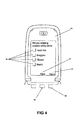
- Figure 4 shows an example of a request for information as displayed by the communications device 15. It has been described above that request for information can take various forms.
- the request for information relates to protective equipment which an operator is required to wear.
- the request for information comprises a plurality of items of protective equipment, each of which is displayed together with a respective selection element 19.
- a user of the communications device can use a cursor key (not shown) to navigate between the selection elements 19.
- a key 20 associated with a "Mark” indicator 21 displayed by the communications device can be pressed to cause selection of the currently highlighted selection element.
- the user can highlight each selection element 19 in turn, and use the key 20 to mark each item.
- the operator responds to the requests for information in this way at step S10 of Figure 3 .
- the user may press a key 22 associated with a "Report” indicator 23 to cause data indicating the marked items to be transmitted to the server 16 over the telecommunications network 18 at step S11.
- the server 16 receives the responses at step S12.
- the responses are stored at the server 16 together with data indicating the device identifier and location identifier.
- step S13 the server determines if the responses received at step S12 are valid.
- this verification involves ensuring that the received data indicates that the user has selected each displayed item of protective equipment.
- steps S8 to S12 may be repeated so as to provide a plurality of requests for information to which responses are received and processed in the manner described above. Additionally, it will be appreciated that some requests for information may not require a particular response. For example a request for information relating to a reason for entering a cell will not have a particular expected response, In such a case the response may not be verified but merely logged by the server 16. Additionally, if it is determined that a response is not as expected, the user may be provided with a further opportunity to provide a response, for example by resending the request for information.
- step S13 If it is determined at step S13 that a response is not as required (e.g. by comparison with stored data) then processing passes to step S7, and entry to the cell is not permitted, If it is determined at step S13 that a valid response has been received in response to the request for information, then at step S14 the server 16 communicates with the controller 3 to control the machinery 6 to enter a safe mode, and also to allow access to the cell 2 by controlling the lock 12. At step S15 the server logs details of entry to the cell for audit purposes.
- Figure 5 shows processing carried out by the controller 13 in response to receipt of an appropriate signal from the server 16.
- the controller 13 receives a signal from the server 16.
- the controller causes the machinery 6 to enter a safe operating mode. Once the safe mode has provided conditions within the cell 2 that are safe for entry of an operator, at step S18 the cell door 11 is unlocked by providing a signal to the lock 12 to allow safe entry by the operator.
- the described method and apparatus for controlling access to a cell ensures that only an authenticated operator can gain access to a cell.
- An operator requires a communications device provided with a valid device identifier for a particular cell, the cell being identified by the location identifier associated with the NFC tag provided near the cell door.
- the server 16 it is straightforward to initialise and modify operator permissions for an entire area of a factory or even for a number of sites through a remote server. This is achieved by updating data stored by the server 16 indicating device identifiers associated with a particular location identifier so as to indicate which device identifiers can be used to gain access to a cell associated with a particular location identifier.
- the described method and apparatus further allows for checks to be performed such as checking and logging confirmation that an operator is wearing the correct personal protection equipment as described above.
- data logged by the server 16 can be provided during an investigation to show that the operator confirmed they were wearing the correct protective equipment.
- Each item of protective equipment may be provided with its own NFC tag.
- An operator may verify correct use of protective equipment by placing the tag of particular protective equipment in proximity of the communications device 15 such that details of the protective equipment (as identified using its NFC tag) are provided to the server 16 over the telecommunications network 18.
- an operator exits the cell 2 and closes the cell door 11.
- the operator places the communications device 15 near the N FC tag 14.
- the communications device 15 receives the location identifier associated with the NFC tag 14 from the NFC tag 14.
- the communications device 15 transmits a restart request to the server 16.
- a restart request includes data indicating the location identifier as received from the NFC tag 14 and the device identifier of the communications device 15.
- the server 16 receives the restart request and logs the request including the location identifier and device identifier as received from the communications device 15.
- the server verifies the restart request. Verification comprises determining whether the device identifier received corresponds to the device identifier that was received during entry verification.
- step S25 it is determined whether verification was successful. If it is determined at step S25 that verification was unsuccessful, processing passes to step S26 and the machinery 6 is not restarted.
- step S25 If it is determined at step S25 that verification was successful, processing passes to step S27 where it is determined if requests for information should be sent to the communications device 15. If no requests for information are to be sent, processing passes to step S28 where restart request is logged, and an appropriate signal is provided to the controller 13. The controller 13 on receiving this signal takes action to activate the lock 12 so as to lock the cell door 11, before causing the machinery 6 to resume normal operation,
- step S29 the server 14 sends a request for further information to communications device 15.
- the request for further information is received at the communications device 15.
- a user response to the request for further information is received at step S31.
- Requests for information provided at step S30 may include requests for confirmation that the cell 2 is clear and that the problem has been resolved. As described previously, a single request for further information may be provided or a series of such requests may be provided with each being sent after a response to a previous request has been verified.
- step S32 the server 16 verifies and logs the responses to the requests for further information and at step S33 it is determined whether the response is acceptable. If it is determined that the response is not acceptable then processing passes to step S26 where restart of the machine is not allowed. If it is determined that the received response is acceptable, processing passes to step S28 where the restart is logged and an appropriate signal sent to the controller 12 as described above,
- the described method and apparatus for controlling access to a cell ensures that only an operator who entered the cell can restart machinery within the cell, given the requirement that the device identifier associated with the device used to gain access to the cell matches the device identifier used to restart the machinery- This prevents accidental restart of the machinery whilst an operator is still inside the cell and therefore prevents harm to the operator.
- Providing requests for information provides an extra level of health and safety assurance as well as providing additional data that can be analysed after the event
- the data that is stored in the process described above with reference to Figures 3 and 6 can be analysed to increase factory efficiency and reduce machinery downtime. For example, a record is maintained of exactly who entered a given cell by storing device identifiers. A record may also be kept of how long an operator was in a cell. This data can be used to analyse and audit machine downtime. It may also be used to control personnel entry to allow only those operators who are relatively quick at remedying problems with particular machinery. The methods can also be used to identify personnel who require further training.
- Further data regarding problems associated with particular machinery may also be stored using the processes described above to obtain further information, so as to identify why an operator is entering a cell.
- This data may be used to identify training needs amongst operators for recurrent problems, or to determine if a particular item of machinery is prone to a particular problem. Once such a problem has been identified, steps can be taken to prevent recurrence. For example maintenance experts may be called to examine a recurrent problem, or the data may be used for early identification and diagnosis of a major problem before it occurs.
- a verification module 25 the communications device 15 obtains the location identifier from the NFC tag 14 and provides the location identifier and the device identifer to the verification module 25 using a short range communications protocol.
- the verification module 25 is arranged to carry out the processing described above, and in particular can provide requests for further information to the communications device 15 and process responses to such requests.
- the verification module 25 is also arranged to provide signals to the controller 13 in the manner described above so as to cause the machinery 6 to enter a safe mode, and to cause the lock 12 to be deactivated.
- the arrangement described with reference to Figure 7 does not rely on communication over the telecommunications network 18 to allow access to the cell 2. Thus, where access to the telecommunications network is limited, the arrangement of Figure 7 may be preferred. However, as described above, it is advantageous to store data in a central server for the purposes of various analysis. Thus, in some embodiments, when the communications device 15 is able to access the telecommunications network 18, the communications device 15 is arranged to provide data to the server 16 for storage. Such data may include data indicating a request for entry to various cells.
- a verification module 26 is associated with the controller 13.
- the verification module 26 is arranged to provide functionality described above with reference to the verification module 25 of Figure 7 ,
- the verification module 26 may be implemented as part of the controller 13, or as a standalone device which is in communication with the controller 13. Communication between the communications device 15 and the verification module 26 is again provided using a suitable short range communication protocol. It can be seen that the arrangement of Figure 8 does not require a connection to the server 16 to obtain entry to the cell 2. However data may be still be provided to the server 16 for storage in the manner described above with reference to Figure 7 .
Abstract
Description
- The present invention relates to methods and apparatus suitable for use in access control. More particularly, but not exclusively, the invention relates to methods and apparatus for controlling and monitoring entry into secure areas.
- Many factories use processes controlled by machines. Many of these processes are fully automated and require only a minimal amount of human interaction, often for the purpose of maintenance. Often a factory has many items of machinery operating in a single area of a factory. Within a single area, each item of machinery may be housed in a respective cell to prevent unauthorised access to particular machinery and to increase safety. If particular machinery in a cell breaks down and requires human interaction, a person is able to attend to that machinery without shutting down other machinery in a factory area which can continue to operate normally within respective other cells.
- Access to a cell may be restricted by an access control system such that only those people who may require access are provided with access. A known access control system uses a lock which requires an access code to be provided for entry to a cell. The access control system is arranged such that machinery within the cell is stopped or placed into a safe mode before access to the cell is allowed. When a user enters an access code the access control system does not allow access to the cell until the machinery has been stopped or placed in a safe mode. The person is then able to attend to the machinery safely.
- While the known systems described above are advantageous in that they allow access to machinery to be controlled in such a way that access is allowed only when such access can be safely allowed, they are disadvantageous in that users must be provided with relevant codes, and further disadvantageous in that each cell is effectively provided with a stand-alone access control system over which there is no centralised control and management.
- It is an object of embodiments of the present invention to obviate or mitigate at least some of the above-mentioned drawbacks.
- According to an aspect of the present invention, there is provided a method and apparatus for controlling access to a restricted area containing machinery. The method comprises receiving from a communications device a location identifier associated with said restricted area and a further identifier, verifying said location identifier and said further identifier and controlling access to said restricted area based upon said verifying. Controlling access to said restricted area comprises providing a control signal to a controller associated with said restricted area. The controller is arranged to control said machinery in response to said control signal.
- The invention allows access to be controlled using communications devices and therefore removes the requirement for memorising of codes for access to a particular cell. A record of entries to cells can be maintained centrally from which it is possible to determine why machinery is stopped and who stopped the machinery. Recurrent problems can be recognised and fixed early before significant loss of productivity.
- The controller may be arranged to control the industrial machinery in response to the control signal to stop operation of the machinery, or cause operation of the machinery only in a safe mode.
- Reference to a "safe mode" is intended to indicate an operating mode of the industrial machinery in which a human operator can safely access the industrial machinery. Thus the particular parameters of a "safe mode" for particular machinery may be determined with reference to that machinery and applicable health and safety guidelines.
- Access to the restricted area may be provided through an access point, and the controller may open said access point if but only if the machinery is in a predetermined state. For example the restricted area may be an enclosure (sometimes known as a cell) within which machinery is housed. In such a case the access point may be a door or other barrier in a boundary wall of the enclosure.
- Receiving and verifying may be carried out at a server. The server may be associated with a plurality of controllers, each controller being associated with a respective restricted area. For example, the identifiers may be provided using a packet data protocol such as GPRS over a mobile telephone network such as a GSM network.
- The location identifier and the further identifier may be received over a wireless communications link. The wireless communications link may be provided by a mobile telephone network. The communications device may be a mobile telephone.
- The method may further comprise storing access control data in a database, based upon the location identifier and the further identifier.
- The method may further comprise providing to the communications device at least one request and receiving from the communications device, in response to the at least one request, at least one response. The at least one response may be verified and controlling access to the restricted area may be further based upon the verifying of the at least one response. The at least one request may request an identification code and/or the at least one request may request information relating to protective equipment. The method may further comprise storing the at least one response in a database.
- A method allowing additional checks to be performed when a person enters a restricted area is provided. Such checks may be intended to ensure that all reasonable safety measures are taken.
- The further identifier may be an identifier associated with the communications device and the further identifier may be an identifier associated with an operator.
- The method may further comprise receiving a request to cause normal operation of the machinery, the request comprising a location identifier and a second further identifier. It may be determined whether the second further identifier and the location identifier satisfy a predetermined criterion and allowing normal operation of the machinery may be allowed based upon the determining. The predetermined criterion may comprise a match between the second further identifier and the further identifier.
- A further aspect of the invention provides a system for controlling access to a restricted area. The system comprises a server arranged to receive from a communications device a location identifier associated with said restricted area and a further identifier and to verify said location identifier and said further identifier, and a controller arranged to control access to said restricted area upon receipt of a control signal from said server. Said control signal is sent from said server to said controller based upon said verification. The system may comprise a communications device in communication with said server.
- There is also provided a method and apparatus for controlling access to a restricted area. The method comprises reading a location identifier from an electronic identification device using a communications device; and transmitting said read location identifier and a further identifier from said communications device to a server, wherein said server is arranged to verify said location identifier and said further identifier and control access to said restricted area based upon said verifying.
- The communications device may be a mobile telephone. The further identifier may be an identifier associated with said communications device
- The method may further comprise receiving at least one request at said communications device, receiving user input indicating at least one response to said at least one request; and transmitting said at least one response to said server, wherein the server is arranged to control access to said restricted area based upon said verifying of the at least one response.
- It will be appreciated that aspects of the invention can be implemented in any convenient form. For example, the invention may be implemented by appropriate computer programs which may be carried out appropriate carrier media which may be tangible carrier media (e.g. disks) or intangible carrier media (e.g. communications signals). Aspects of the invention may also be implemented using suitable apparatus which may take the form of pragrammable computers running computer programs arranged to implement the invention.
- Embodiments of various aspects of the present invention will now be described, by way of example only, with reference to the accompanying drawings, in which:
-
Figure 1 is a schematic illustration in plan view of a factory area showing four machine cells, one of which has a fault; -
Figure 2 is a schematic illustration of an access control system according to a first embodiment of the present invention; -
Figure 3 is a flow chart showing processing carried out to allow access to a cell in the system ofFigure 2 ; -
Figure 4 is a schematic illustration of a communications device display, as used in an embodiment of the invention; -
Figure 5 is a flow chart showing processing carried out at a controller following receipt of an entry request; -
Figure 6 is a flow chart showing processing carried out to restart stopped machinery; -
Figure 7 is a schematic illustration of an access control system according to a second embodiment of the present invention; and -
Figure 8 is a schematic illustration of an access control system according to a third embodiment of the present invention. - Referring to
Figure 1 , a portion of afactory floor 1 containing fourcells cell respective machinery Machinery 6 contained withincell 2 requires attention from anoperator 10, such as an engineer, as indicated by "STOP", whilemachinery 7, 8, 9 incells machinery machinery - Each of the
cells - Providing each item of
machinery own cell - Referring now to
Figure 2 , a system for controlling access to acell 2 is shown. Access to thecell 2 is provided through acell door 11 which is securable in a closed position by alock 12. Thecell 2 contains acontroller 13, which controls safe access to thecell 2. Thecontroller 13 is connected to thelock 12 to control opening of thecell door 11 and further connected to themachinery 6 to control operation of themachinery 6. - The
controller 13 is arranged such that thelock 12 is provided with a signal allowing the door to be opened only when a suitable control signal has been provided to themachinery 6 to place themachinery 6 in a safe mode. The safe mode may prevent operation of themachinery 6 or invoke a limit on operation of themachinery 6 for example by limiting torque, speed or position of themachinery 6. Thecontroller 13 can be implemented in any suitable way, and in some embodiments thecontroller 13 comprises software components and hardware components. - The
cell 2 is further provided with a near field communication (NFC)tag 14. NFC is a short-range high frequency wireless communication technology which enables the exchange of data between devices over about a 10 centimetre (around 4 inch) distance. The technology is an extension of the ISO 14443 proximity-card standard that combines the interface of a smartcard and a reader into a single device. TheNFC tag 14 is provided in a suitable location in relation to thecell 2, for example close to thecell door 11. - A
communication device 15 containing near field communications technology is shown. Preferably the communication device is a mobile telephone, although other devices such as radio-frequency handsets or simple badge-like devices may be used. NFC enabled mobile telephones are currently available such as the Nokia 6131 NFC, available from Nokia of Helsinki, Finland. Any operator requiring entry to areas of the factory with restricted access is provided with a communications device containing near field communications technology. The operator is further provided with an operator NFC tag which is initially read by the communications device to provide the communications device with an identifier. The identifier read from the the NFC tag can then be used by the communications device as described below. - The
communication device 15 is arranged such that when placed in proximity of theNFC tag 14, an identifier associated with thecell 2 is provided from theNFC tag 14 to thecommunications device 15. - A
server 16 is also provided. Theserver 16 is arranged to communicate with thecontroller 13 through a local area network (LAN) 17 provided within the factory. Theserver 16 is further arranged to receive and transmit data over atelecommunications network 18. In this way, where thecommunication device 15 is a mobile telephone or other device with the ability to connect to thetelecommunications network 18, data may be transmitted between thecommunications device 15 and theserver 16 over thetelecommunications network 18. - The
communications device 15 communicates the location identifier obtained from theNFC tag 14, together with the identifier associated with thecommunications device 15 as read from the operator NFC tag to theserver 16 over thetelecommunications network 18. Theserver 16 verifies the permission of a user of the communications device 15 (as determined by the identifier associated with the communications device 15) to enter the cell 2 (based upon the location identifier associated with the NFC tag 14). Theserver 16 may further send requests for further information to thecommunications device 15 to further verify entry, as described in further detail below. - The
server 16 is arranged to process the location identifier and the identifier associated with thecommunications device 15 together with responses to any provided requests for further information. If it is determined that received identifiers and the responses satisfy predetermined criteria, theserver 16 provides a signal to thecontroller 13 over theLAN 17. The provided signal is arranged to cause thecontroller 13 to cause themachinery 6 to operate in a safe mode, and when this has happened, to cause the controller to unlock thecell door 11 by providing a signal to thelock 12. - In the described embodiment signals are provided from the
server 16 to thecontroller 13 over theLAN 17. TheLAN 17 can be a wired or wireless network. It will be appreciated that it may not be possible to provide such a LAN, and in such a case it is possible to provide a communications path from theserver 16 to thecontroller 13 in any suitable way, for example using thetelecommunications network 18 to which thecontroller 13 may be connected. - Requests for further information may include verification questions sent to the
communications device 15, such as a request that a PIN code is entered. In this way the operator of thecommunications device 15 can be confirmed as an authorised operator of thecommunications device 15. Requests for further information may also include health and safety questions such as verification of correct wearing of protective equipment required for safe entry tocell 2. Theserver 16 is arranged to store responses received to requests for further information, thus providing a record at the server of responses received, for example that the operator has confirmed that all relevant protective equipment is correctly in place. - A further example of a request-for further information is a question relating to the reason for requesting entry to the cell. An answer to such a request may take the form of data indicating the nature of a problem with the machinery. By keeping a record of problems associated with particular machinery it is possible to identify recurrent problems that may cause downtime and to resolve such problems through either replacement of affected parts or calling an engineer to further investigate the problem. In this way long term down time of a given device may be prevented.
- It vall be appreciated that the nature of the requests for further information will be dependent upon the particular environment in which the described system is employed. For example in the nuclear industry a request for further information could be to check if an operator is waring a radiation protection suit.
- The operation of the embodiment of
Figure 2 will now be described in further detail with reference toFigure 3 . - Referring to
Figure 3 , at step S1 an operator places acommunications device 15 with near field communications functionality near theNFC tag 14. At step S2 thecommunications device 15 receives the location identifier from theNFC tag 14 using the NFC protocol, and at step S3 thecommunications device 15 transmits its device identifier and the location identifier to theserver 16. At step S4 theserver 16 receives and logs the entry request, including the device identifier of thecommunications device 15 and the location identifier of theNFC tag 14. - The device identifier can be an identifier which is inherently associated with the
communications device 15. For example, where thecommunications device 15 is a mobile telephone, the device identifier can be an identifier associated with the mobile telephone handset, or with a SIM card inserted into the mobile telephone. For example, the device identifier may be an International Mobile Equipment Identity (IMEI). In alternative embodiments the device identifier may not be inherently associated with thecommunications device 15, but may instead be based upon an identifier input to the communications device by a user thereof. - At step S5 the server verifies the received data by determining whether stored data indicates that the device identifier should allow access to the cell associated with the location identifier. The verification process be implemented using a look up table or any other suitable method.
- At step S6 if the verification was unsuccessful, processing passes to step S7 where no signal is provided from the
server 16 to thecontroller 13, thereby preventing thecell door 11 being opened. Data indicating that entry is not permitted may be provided to thecommunications device 15 using thetelecommunications network 18. - If it is determined at step 86 verification was successful, processing passes to step S8. At step S8 the
server 14 sends a request for information to thecommunications device 15 over thetelecommunications network 18. - At step S9 the
communications device 15 receives the request for information and data determined by the request for information is displayed to the user on a display screen of thecommunications device 15 using software provided on the communications device.Figure 4 shows an example of a request for information as displayed by thecommunications device 15. It has been described above that request for information can take various forms. In the example ofFigure 4 , the request for information relates to protective equipment which an operator is required to wear. The request for information comprises a plurality of items of protective equipment, each of which is displayed together with arespective selection element 19. A user of the communications device can use a cursor key (not shown) to navigate between theselection elements 19. When a particular selection element is highlighted, a key 20 associated with a "Mark"indicator 21 displayed by the communications device can be pressed to cause selection of the currently highlighted selection element. In this way, the user can highlight eachselection element 19 in turn, and use the key 20 to mark each item. The operator responds to the requests for information in this way at step S10 ofFigure 3 . - When all items are marked, the user may press a key 22 associated with a "Report"
indicator 23 to cause data indicating the marked items to be transmitted to theserver 16 over thetelecommunications network 18 at step S11. - The
server 16 receives the responses at step S12. The responses are stored at theserver 16 together with data indicating the device identifier and location identifier. - At step S13 the server determines if the responses received at step S12 are valid. In the example of
Figure 4 , this verification involves ensuring that the received data indicates that the user has selected each displayed item of protective equipment. - It will be appreciated that in some embodiments steps S8 to S12 may be repeated so as to provide a plurality of requests for information to which responses are received and processed in the manner described above. Additionally, it will be appreciated that some requests for information may not require a particular response. For example a request for information relating to a reason for entering a cell will not have a particular expected response, In such a case the response may not be verified but merely logged by the
server 16. Additionally, if it is determined that a response is not as expected, the user may be provided with a further opportunity to provide a response, for example by resending the request for information. - If it is determined at step S13 that a response is not as required (e.g. by comparison with stored data) then processing passes to step S7, and entry to the cell is not permitted, If it is determined at step S13 that a valid response has been received in response to the request for information, then at step S14 the
server 16 communicates with thecontroller 3 to control themachinery 6 to enter a safe mode, and also to allow access to thecell 2 by controlling thelock 12. At step S15 the server logs details of entry to the cell for audit purposes. -
Figure 5 shows processing carried out by thecontroller 13 in response to receipt of an appropriate signal from theserver 16. At step S16 thecontroller 13 receives a signal from theserver 16. At step S17 the controller causes themachinery 6 to enter a safe operating mode. Once the safe mode has provided conditions within thecell 2 that are safe for entry of an operator, at step S18 thecell door 11 is unlocked by providing a signal to thelock 12 to allow safe entry by the operator. - From the preceding description it can be seen that the described method and apparatus for controlling access to a cell ensures that only an authenticated operator can gain access to a cell. An operator requires a communications device provided with a valid device identifier for a particular cell, the cell being identified by the location identifier associated with the NFC tag provided near the cell door. By appropriately configuring the
server 16 it is straightforward to initialise and modify operator permissions for an entire area of a factory or even for a number of sites through a remote server. This is achieved by updating data stored by theserver 16 indicating device identifiers associated with a particular location identifier so as to indicate which device identifiers can be used to gain access to a cell associated with a particular location identifier. - It is common for employers to provide communications devices such as mobile telephones to employees and these devices are usually kept with the employee at all times. An operator is unlikely to forget or misplace their communications device, meaning that the use of communications devices in the manner described above provides benefits as compared with systems which provide access using, for example, a swipe card. Near field communications technology is currently provided in a number of mobile telephones, meaning that communications devices which are usable in the methods described above are readily obtainable.
- The described method and apparatus further allows for checks to be performed such as checking and logging confirmation that an operator is wearing the correct personal protection equipment as described above. In the event of an incident, data logged by the
server 16 can be provided during an investigation to show that the operator confirmed they were wearing the correct protective equipment. Each item of protective equipment may be provided with its own NFC tag. An operator may verify correct use of protective equipment by placing the tag of particular protective equipment in proximity of thecommunications device 15 such that details of the protective equipment (as identified using its NFC tag) are provided to theserver 16 over thetelecommunications network 18. - Once an operator has entered a cell, it is desirable that it is not possible for the machinery within the cell to operate in a mode other than the safe mode until the operator has left the cell and the
cell door 11 has been closed such that it is safe for the machinery to be restarted. The process of restarting a device in a cell after an operator has exited the cell will now be described with reference toFigure 6 . - Referring to
Figure 6 , at step S19 an operator exits thecell 2 and closes thecell door 11. At step S20 the operator places thecommunications device 15 near theN FC tag 14. At step S21 thecommunications device 15 receives the location identifier associated with theNFC tag 14 from theNFC tag 14. At step S22 thecommunications device 15 transmits a restart request to theserver 16. A restart request includes data indicating the location identifier as received from theNFC tag 14 and the device identifier of thecommunications device 15. - At step S23 the
server 16 receives the restart request and logs the request including the location identifier and device identifier as received from thecommunications device 15. At step S24 the server verifies the restart request. Verification comprises determining whether the device identifier received corresponds to the device identifier that was received during entry verification. - At step S25 it is determined whether verification was successful. If it is determined at step S25 that verification was unsuccessful, processing passes to step S26 and the
machinery 6 is not restarted. - If it is determined at step S25 that verification was successful, processing passes to step S27 where it is determined if requests for information should be sent to the
communications device 15. If no requests for information are to be sent, processing passes to step S28 where restart request is logged, and an appropriate signal is provided to thecontroller 13. Thecontroller 13 on receiving this signal takes action to activate thelock 12 so as to lock thecell door 11, before causing themachinery 6 to resume normal operation, - If it is determined at step S27 that requests for further information are to be sent, then at step S29 the
server 14 sends a request for further information tocommunications device 15. At step S30 the request for further information is received at thecommunications device 15. A user response to the request for further information is received at step S31. Requests for information provided at step S30 may include requests for confirmation that thecell 2 is clear and that the problem has been resolved. As described previously, a single request for further information may be provided or a series of such requests may be provided with each being sent after a response to a previous request has been verified. - At step S32 the
server 16 verifies and logs the responses to the requests for further information and at step S33 it is determined whether the response is acceptable. If it is determined that the response is not acceptable then processing passes to step S26 where restart of the machine is not allowed. If it is determined that the received response is acceptable, processing passes to step S28 where the restart is logged and an appropriate signal sent to thecontroller 12 as described above, - From the preceding description it can be seen that the described method and apparatus for controlling access to a cell ensures that only an operator who entered the cell can restart machinery within the cell, given the requirement that the device identifier associated with the device used to gain access to the cell matches the device identifier used to restart the machinery- This prevents accidental restart of the machinery whilst an operator is still inside the cell and therefore prevents harm to the operator. Providing requests for information provides an extra level of health and safety assurance as well as providing additional data that can be analysed after the event
- The data that is stored in the process described above with reference to
Figures 3 and6 can be analysed to increase factory efficiency and reduce machinery downtime. For example, a record is maintained of exactly who entered a given cell by storing device identifiers. A record may also be kept of how long an operator was in a cell. This data can be used to analyse and audit machine downtime. It may also be used to control personnel entry to allow only those operators who are relatively quick at remedying problems with particular machinery. The methods can also be used to identify personnel who require further training. - Further data regarding problems associated with particular machinery may also be stored using the processes described above to obtain further information, so as to identify why an operator is entering a cell. This data may be used to identify training needs amongst operators for recurrent problems, or to determine if a particular item of machinery is prone to a particular problem. Once such a problem has been identified, steps can be taken to prevent recurrence. For example maintenance experts may be called to examine a recurrent problem, or the data may be used for early identification and diagnosis of a major problem before it occurs.
- It will be appreciated that other data items can be stored to provide detailed records of a factory floor operation. The stored data can be analysed to develop best practice methods.
- In alternative embodiments it may not be possible or desirable to provide a network connection between the
communications device 15 and theserver 16. In such embodiments an alternate arrangement of hardware may be provided. Two example arrangements are shown inFigures 7 and8 and discussed below. - Referring now to
Figure 7 , an alternative arrangement of hardware to that ofFigure 2 is shown. In the arrangement ofFigure 7 , verification of a particular combination of device identifier and location identifier is carried out by averification module 25. Here, thecommunications device 15 obtains the location identifier from theNFC tag 14 and provides the location identifier and the device identifer to theverification module 25 using a short range communications protocol. Theverification module 25 is arranged to carry out the processing described above, and in particular can provide requests for further information to thecommunications device 15 and process responses to such requests. Theverification module 25 is also arranged to provide signals to thecontroller 13 in the manner described above so as to cause themachinery 6 to enter a safe mode, and to cause thelock 12 to be deactivated. - It can be seen that the arrangement described with reference to
Figure 7 does not rely on communication over thetelecommunications network 18 to allow access to thecell 2. Thus, where access to the telecommunications network is limited, the arrangement ofFigure 7 may be preferred. However, as described above, it is advantageous to store data in a central server for the purposes of various analysis. Thus, in some embodiments, when thecommunications device 15 is able to access thetelecommunications network 18, thecommunications device 15 is arranged to provide data to theserver 16 for storage. Such data may include data indicating a request for entry to various cells. - Referring now to
Figure 8 , a further hardware arrangement is shown. Here, averification module 26 is associated with thecontroller 13. Theverification module 26 is arranged to provide functionality described above with reference to theverification module 25 ofFigure 7 , Theverification module 26 may be implemented as part of thecontroller 13, or as a standalone device which is in communication with thecontroller 13. Communication between thecommunications device 15 and theverification module 26 is again provided using a suitable short range communication protocol. It can be seen that the arrangement ofFigure 8 does not require a connection to theserver 16 to obtain entry to thecell 2. However data may be still be provided to theserver 16 for storage in the manner described above with reference toFigure 7 . - Whilst the embodiments described herein use near field communication, it will be appreciated that any suitable communications path can be used such as RFID. It will further be appreciated that reference to "machinery" in the foregoing description should be construed broadly to cover any moving process to which access is to be controlled.
- Various modifications to the described embodiments will be readily apparent to the appropriately skilled person.
Claims (16)
- A method of controlling access to a restricted area containing machinery comprising:receiving from a communications device a location identifier associated with said restricted area and a further identifier;verifying said location identifier and said further identifier; andcontrolling access to said restricted area based upon said verifying;wherein controlling access to said restricted area comprises providing a control signal to a controller associated with said restricted area, said controller being arranged to control said machinery in response to said control signal.
- A method according to claim 1, wherein said controller is arranged to control said machinery in response to said control signal to stop operation of said machinery, or cause operation of said machinery only in a safe mode.
- A method according to claim 1 or 2, wherein access to said restricted area is provided through an access point, and said controller opens said access point if but only if said machinery is in a predetermined state.
- A method according to claim 4, wherein said receving and said verifying are carried out at a server, and the server is associated with a plurality of controllers, each controller being associated with a respective restricted area.
- A method according to any preceding claim, wherein said location identifier and said further identifier are received over a wireless communications link.
- A method according to any preceding claim, further comprising storing access control data in a database, based upon said location identifier and said further identifier.
- A method according to any preceding claim, further comprising:providing to said communications device at least one request;receiving from said communications device, in response to said at least one request, at least one response;verifying said at least one response;wherein said controlling access to said restricted area is further based upon said verifying of the at least one response.
- A method according to claim 7, wherein said at least one request requests an identification code or information relating to protective equipment.
- A method according to any preceding claim, further comprising:receiving a request to cause normal operation of said machinery, said request comprising a location identifier and a second further identifier;determining whether said second further identifier and said location identifier satisfy a predetermined criterion;allowing normal operation of said machinery based upon said determining.
- A method according to claim 9, wherein said predetermined criterion comprises a match between said second further identifier and said further identifier.
- A computer apparatus for controlling access to a restricted area comprising:means for receiving from a communications device a location identifier associated with said restricted area and a further identifier;means for verifying said location identifier and said further identifier; andmeans for controlling access to said restricted area based upon said verifying.
- A method of controlling access to a restricted area, the method comprising:reading a location identifier from an electronic identification device using a communications device;transmitting said read location identifier and a further identifier from said communications device to a server, wherein said server is arranged to verify said location identifier and said further identifier and control access to said restricted area based upon said verifying.
- A method according to any one of claims 1 to 10 or claim 12, wherein said further identifier is an identifier associated with said communications device or an identifier associated with an operator.
- A computer readable medium carrying a computer program comprising computer readable instructions configured to cause a computer to carry our a method according to any one of claims 1 to 10 or claim 12 or 13.
- A computer apparatus for controlling access to a restricted area comprising:a memory storing processor readable instructions; anda processor arranged to read and execute instructions stored in said memory;wherein said processor readable instructions comprise instructions arranged to control the computer to carry out a method according to any one of claims 1 to 10 or claims 12 to 14.
- Apparatus for controlling access to a restricted area, the apparatus comprising:means for reading a location identifier from an electronic identification device;means for transmitting said read location identifier and a further identifier from to a server, wherein said server is arranged to verify said location identifier and said further identifier and control access to said restricted area based upon said verifying.
Applications Claiming Priority (1)
| Application Number | Priority Date | Filing Date | Title |
|---|---|---|---|
| GBGB0821482.7A GB0821482D0 (en) | 2008-11-25 | 2008-11-25 | Access control |
Publications (2)
| Publication Number | Publication Date |
|---|---|
| EP2192560A1 true EP2192560A1 (en) | 2010-06-02 |
| EP2192560B1 EP2192560B1 (en) | 2014-02-12 |
Family
ID=40230762
Family Applications (1)
| Application Number | Title | Priority Date | Filing Date |
|---|---|---|---|
| EP09252652.4A Not-in-force EP2192560B1 (en) | 2008-11-25 | 2009-11-19 | Access control |
Country Status (3)
| Country | Link |
|---|---|
| US (1) | US8508332B2 (en) |
| EP (1) | EP2192560B1 (en) |
| GB (1) | GB0821482D0 (en) |
Cited By (6)
| Publication number | Priority date | Publication date | Assignee | Title |
|---|---|---|---|---|
| US20130335193A1 (en) * | 2011-11-29 | 2013-12-19 | 1556053 Alberta Ltd. | Electronic wireless lock |
| EP2816532A3 (en) * | 2013-06-20 | 2015-01-07 | Honeywell International Inc. | Systems and methods for enabling access control via mobile devices |
| EP2833330A1 (en) * | 2013-07-30 | 2015-02-04 | Paxton Access Limited | Communication method and system |
| US9591693B2 (en) | 2013-07-30 | 2017-03-07 | Paxon Access Limited | Communication method and system |
| US10166673B2 (en) | 2014-04-04 | 2019-01-01 | Abb Schweiz Ag | Portable apparatus for controlling robot and method thereof |
| US11887424B2 (en) | 2019-06-12 | 2024-01-30 | Honeywell International Inc. | Access control system using mobile device |
Families Citing this family (48)
| Publication number | Priority date | Publication date | Assignee | Title |
|---|---|---|---|---|
| AU2011224140B2 (en) * | 2010-09-27 | 2015-12-17 | Multitrode Pty Ltd | Controlling Access to a Control Panel Compartment |
| US20130214902A1 (en) * | 2010-12-02 | 2013-08-22 | Viscount Systems Inc. | Systems and methods for networks using token based location |
| US8941465B2 (en) * | 2010-12-02 | 2015-01-27 | Viscount Security Systems Inc. | System and method for secure entry using door tokens |
| US20140002236A1 (en) * | 2010-12-02 | 2014-01-02 | Viscount Security Systems Inc. | Door Lock, System and Method for Remotely Controlled Access |
| KR101514029B1 (en) * | 2010-12-31 | 2015-04-21 | 주식회사 케이티 | Method and apparatus for entry authentication using user terminal |
| CA2823909A1 (en) * | 2011-01-07 | 2012-07-12 | Delphian Systems, LLC | System and method for access control via mobile device |
| US9544977B2 (en) | 2011-06-30 | 2017-01-10 | Lutron Electronics Co., Inc. | Method of programming a load control device using a smart phone |
| US9386666B2 (en) | 2011-06-30 | 2016-07-05 | Lutron Electronics Co., Inc. | Method of optically transmitting digital information from a smart phone to a control device |
| US10271407B2 (en) | 2011-06-30 | 2019-04-23 | Lutron Electronics Co., Inc. | Load control device having Internet connectivity |
| US20130222122A1 (en) | 2011-08-29 | 2013-08-29 | Lutron Electronics Co., Inc. | Two-Part Load Control System Mountable To A Single Electrical Wallbox |
| US20130169815A1 (en) * | 2011-12-29 | 2013-07-04 | Mark Douglas Carney | Equipment enclosures with remote logging, authorization and monitoring |
| US9317669B1 (en) * | 2012-02-01 | 2016-04-19 | A9.Com, Inc. | Verifying ownership of content |
| US10244086B2 (en) | 2012-12-21 | 2019-03-26 | Lutron Electronics Co., Inc. | Multiple network access load control devices |
| US10019047B2 (en) | 2012-12-21 | 2018-07-10 | Lutron Electronics Co., Inc. | Operational coordination of load control devices for control of electrical loads |
| US9413171B2 (en) | 2012-12-21 | 2016-08-09 | Lutron Electronics Co., Inc. | Network access coordination of load control devices |
| US9665088B2 (en) | 2014-01-31 | 2017-05-30 | Fisher-Rosemount Systems, Inc. | Managing big data in process control systems |
| US10649449B2 (en) | 2013-03-04 | 2020-05-12 | Fisher-Rosemount Systems, Inc. | Distributed industrial performance monitoring and analytics |
| US10678225B2 (en) | 2013-03-04 | 2020-06-09 | Fisher-Rosemount Systems, Inc. | Data analytic services for distributed industrial performance monitoring |
| US9823626B2 (en) | 2014-10-06 | 2017-11-21 | Fisher-Rosemount Systems, Inc. | Regional big data in process control systems |
| US10909137B2 (en) | 2014-10-06 | 2021-02-02 | Fisher-Rosemount Systems, Inc. | Streaming data for analytics in process control systems |
| US9558220B2 (en) | 2013-03-04 | 2017-01-31 | Fisher-Rosemount Systems, Inc. | Big data in process control systems |
| US10866952B2 (en) | 2013-03-04 | 2020-12-15 | Fisher-Rosemount Systems, Inc. | Source-independent queries in distributed industrial system |
| US10223327B2 (en) | 2013-03-14 | 2019-03-05 | Fisher-Rosemount Systems, Inc. | Collecting and delivering data to a big data machine in a process control system |
| US9397836B2 (en) | 2014-08-11 | 2016-07-19 | Fisher-Rosemount Systems, Inc. | Securing devices to process control systems |
| US10282676B2 (en) | 2014-10-06 | 2019-05-07 | Fisher-Rosemount Systems, Inc. | Automatic signal processing-based learning in a process plant |
| US10649424B2 (en) | 2013-03-04 | 2020-05-12 | Fisher-Rosemount Systems, Inc. | Distributed industrial performance monitoring and analytics |
| US10386827B2 (en) | 2013-03-04 | 2019-08-20 | Fisher-Rosemount Systems, Inc. | Distributed industrial performance monitoring and analytics platform |
| US9804588B2 (en) | 2014-03-14 | 2017-10-31 | Fisher-Rosemount Systems, Inc. | Determining associations and alignments of process elements and measurements in a process |
| US10649412B2 (en) | 2013-03-15 | 2020-05-12 | Fisher-Rosemount Systems, Inc. | Method and apparatus for seamless state transfer between user interface devices in a mobile control room |
| CN107885494B (en) | 2013-03-15 | 2021-09-10 | 费希尔-罗斯蒙特系统公司 | Method and computer system for analyzing process control data |
| US10135629B2 (en) | 2013-03-15 | 2018-11-20 | Lutron Electronics Co., Inc. | Load control device user interface and database management using near field communication (NFC) |
| GB2533675B (en) * | 2013-07-30 | 2018-02-07 | Paxton Access Ltd | Communication method and system |
| US9253198B2 (en) * | 2013-10-29 | 2016-02-02 | Mapquest, Inc. | Systems and methods for geolocation-based authentication and authorization |
| US20150284231A1 (en) * | 2014-04-05 | 2015-10-08 | RF Identity, Inc. | Systems and methods for validation of personal protection equipment on aerial work platforms |
| EP3161564A4 (en) * | 2014-06-25 | 2018-01-24 | Concorde Asia Pte. Ltd. | Security control system for granting access and security control method thereof |
| EP2978276A1 (en) * | 2014-07-25 | 2016-01-27 | The Swatch Group Research and Development Ltd. | Information station with multiple communication interfaces |
| US10168691B2 (en) | 2014-10-06 | 2019-01-01 | Fisher-Rosemount Systems, Inc. | Data pipeline for process control system analytics |
| US10109128B2 (en) * | 2015-05-29 | 2018-10-23 | Kawasaki Jukogyo Kabushiki Kaisha | Access control system to interference area |
| US10503483B2 (en) | 2016-02-12 | 2019-12-10 | Fisher-Rosemount Systems, Inc. | Rule builder in a process control network |
| CN105785959B (en) * | 2016-05-12 | 2018-04-24 | 宁波大学 | Modern plant device management method based on near-field communication |
| US10944858B2 (en) * | 2016-12-13 | 2021-03-09 | Lenovo (Singapore) Pte. Ltd. | Display of property restrictions via wireless device |
| US11157710B2 (en) * | 2018-05-04 | 2021-10-26 | Rowan Companies, Inc. | System and method for monitoring operations and personnel in designated areas on offshore unit |
| US11281877B2 (en) | 2018-06-26 | 2022-03-22 | Columbia Insurance Company | Methods and systems for guided lock-tag-try process |
| US11605254B1 (en) * | 2018-09-07 | 2023-03-14 | Amazon Technologies, Inc. | Tamper detection for beacons using radio frequency tags |
| CN109377614B (en) * | 2018-10-29 | 2020-02-07 | 重庆中科云从科技有限公司 | Face access control recognition method, system, computer storage medium and equipment |
| GB2590608B (en) * | 2019-11-28 | 2022-08-17 | Paxton Access Ltd | Access control system and method |
| GB2608692A (en) * | 2019-11-28 | 2023-01-11 | Paxton Access Ltd | Access control system and method |
| WO2021229134A1 (en) * | 2020-05-13 | 2021-11-18 | Kone Corporation | Access solution for conveyor systems |
Citations (3)
| Publication number | Priority date | Publication date | Assignee | Title |
|---|---|---|---|---|
| US20040148039A1 (en) * | 2003-01-24 | 2004-07-29 | Farchmin David W | Position based machine control in an industrial automation environment |
| WO2006136662A1 (en) * | 2005-06-23 | 2006-12-28 | Mohinet Oy | Communication method of access control system |
| US20070205861A1 (en) * | 2006-02-23 | 2007-09-06 | Rockwell Automation Technologies, Inc. | RFID/biometric area protection |
Family Cites Families (14)
| Publication number | Priority date | Publication date | Assignee | Title |
|---|---|---|---|---|
| US4101235A (en) * | 1977-06-27 | 1978-07-18 | Nelson Donald F | Parking lot exit control means |
| JP2700710B2 (en) * | 1990-06-21 | 1998-01-21 | 新キャタピラー三菱株式会社 | Warning device for construction machinery |
| US5288164A (en) * | 1992-01-07 | 1994-02-22 | Nasatka Ralph G | Combined vehicle barrier |
| FI92172C (en) * | 1993-02-09 | 1994-10-10 | Valmet Paper Machinery Inc | Method for retrieving end tags from stacks |
| US5991749A (en) * | 1996-09-11 | 1999-11-23 | Morrill, Jr.; Paul H. | Wireless telephony for collecting tolls, conducting financial transactions, and authorizing other activities |
| US6570487B1 (en) * | 1997-01-24 | 2003-05-27 | Axcess Inc. | Distributed tag reader system and method |
| US6945303B2 (en) * | 2000-08-24 | 2005-09-20 | Weik Iii Martin Herman | Intruder, theft and vandalism deterrent management system for controlling a parking area |
| US6810353B2 (en) * | 2000-10-26 | 2004-10-26 | The United States Of America As Represented By The Secretary Of The Department Of Health And Human Services, Centers For Disease Control | Non-directional magnet field based proximity receiver with multiple warning and machine shutdown capability |
| US7768549B2 (en) * | 2001-06-08 | 2010-08-03 | Honeywell International Inc. | Machine safety system with mutual exclusion zone |
| JP2004154916A (en) * | 2002-11-08 | 2004-06-03 | Fanuc Ltd | Safety device of automatic mechanical system |
| FR2894318B1 (en) * | 2005-12-07 | 2008-03-07 | Lectra Sa | ACTIVE SECURITY MANAGEMENT METHOD FOR AN AUTOMATIC WORKING MACHINE. |
| JP4699299B2 (en) | 2006-06-28 | 2011-06-08 | 日本電信電話株式会社 | Electronic key opening and closing system and method |
| US8040216B2 (en) * | 2006-09-21 | 2011-10-18 | Ubiquity Holdings, Inc. | Virtual entry assistant using automated greeter |
| NL1033539C2 (en) | 2007-03-13 | 2008-09-17 | Nedap Nv | Access control system using mobile phone with NFC technology, compares authorization information on server with identification codes for phone and electronic lock |
-
2008
- 2008-11-25 GB GBGB0821482.7A patent/GB0821482D0/en not_active Ceased
-
2009
- 2009-11-19 EP EP09252652.4A patent/EP2192560B1/en not_active Not-in-force
- 2009-11-25 US US12/626,258 patent/US8508332B2/en active Active
Patent Citations (3)
| Publication number | Priority date | Publication date | Assignee | Title |
|---|---|---|---|---|
| US20040148039A1 (en) * | 2003-01-24 | 2004-07-29 | Farchmin David W | Position based machine control in an industrial automation environment |
| WO2006136662A1 (en) * | 2005-06-23 | 2006-12-28 | Mohinet Oy | Communication method of access control system |
| US20070205861A1 (en) * | 2006-02-23 | 2007-09-06 | Rockwell Automation Technologies, Inc. | RFID/biometric area protection |
Cited By (8)
| Publication number | Priority date | Publication date | Assignee | Title |
|---|---|---|---|---|
| US20130335193A1 (en) * | 2011-11-29 | 2013-12-19 | 1556053 Alberta Ltd. | Electronic wireless lock |
| EP2816532A3 (en) * | 2013-06-20 | 2015-01-07 | Honeywell International Inc. | Systems and methods for enabling access control via mobile devices |
| US10395452B2 (en) | 2013-06-20 | 2019-08-27 | Honeywell International Inc. | Systems and methods for enabling access control via mobile devices |
| EP2833330A1 (en) * | 2013-07-30 | 2015-02-04 | Paxton Access Limited | Communication method and system |
| US9591693B2 (en) | 2013-07-30 | 2017-03-07 | Paxon Access Limited | Communication method and system |
| EP2833330B1 (en) | 2013-07-30 | 2018-07-18 | Paxton Access Limited | Communication method and system |
| US10166673B2 (en) | 2014-04-04 | 2019-01-01 | Abb Schweiz Ag | Portable apparatus for controlling robot and method thereof |
| US11887424B2 (en) | 2019-06-12 | 2024-01-30 | Honeywell International Inc. | Access control system using mobile device |
Also Published As
| Publication number | Publication date |
|---|---|
| US8508332B2 (en) | 2013-08-13 |
| EP2192560B1 (en) | 2014-02-12 |
| GB0821482D0 (en) | 2008-12-31 |
| US20100127821A1 (en) | 2010-05-27 |
Similar Documents
| Publication | Publication Date | Title |
|---|---|---|
| EP2192560B1 (en) | Access control | |
| US10395459B2 (en) | Safety lockout systems and methods | |
| EP3408837B1 (en) | Systems and methods for remote access rights and verification | |
| US10805304B2 (en) | Edge server and management server | |
| US10257707B2 (en) | Method for safe access to a field device | |
| CN105006045A (en) | NFC cell phone dynamic password entrance guard system and control method thereof | |
| CN112734248A (en) | Real estate intelligent management system | |
| KR102063569B1 (en) | Method and apparatus for controlling a door opening using a portable terminal | |
| JP2007316962A (en) | Worker management method, and information processor, worker terminal and program used therefor | |
| CN109034294A (en) | A kind of air defence instrument box supervisory systems and monitoring and managing method | |
| US10162313B2 (en) | Equipment isolation system | |
| US9563992B2 (en) | System and method of associating, assigning, and authenticating users with personal protective equipment using biometrics | |
| CN111640222A (en) | Safety cabinet device, unlocking method and unlocking system | |
| JP2003063750A (en) | Security system for elevator maintenance tool, portable terminal loaded on maintenance tool and monitoring center device | |
| EP3496056A1 (en) | Access key card that cancels automatically for safety and security | |
| CN113763603B (en) | Information processing apparatus, information processing method, computer-readable storage medium, and portable terminal | |
| KR101553231B1 (en) | Security management system for switch apparatus | |
| KR100785356B1 (en) | Integrational management system for arcade | |
| KR20160102948A (en) | 2-channel authentication system and method for a financial transfer | |
| CN110349302A (en) | One kind can program intelligent entrance guard control protection operational method and its system | |
| US20170003663A1 (en) | Equipment Isolation System | |
| CN114299641B (en) | Door control noninductive unlocking method and system | |
| EP2238730B1 (en) | Method for the remote management of mobile devices and mobile device suited thereto | |
| CN112489271A (en) | Intelligent granary access control system and working method thereof | |
| KR20100000837A (en) | User access notification system |
Legal Events
| Date | Code | Title | Description |
|---|---|---|---|
| PUAI | Public reference made under article 153(3) epc to a published international application that has entered the european phase |
Free format text: ORIGINAL CODE: 0009012 |
|
| AK | Designated contracting states |
Kind code of ref document: A1 Designated state(s): AT BE BG CH CY CZ DE DK EE ES FI FR GB GR HR HU IE IS IT LI LT LU LV MC MK MT NL NO PL PT RO SE SI SK SM TR |
|
| AX | Request for extension of the european patent |
Extension state: AL BA RS |
|
| 17P | Request for examination filed |
Effective date: 20101202 |
|
| 17Q | First examination report despatched |
Effective date: 20110103 |
|
| RAP1 | Party data changed (applicant data changed or rights of an application transferred) |
Owner name: FT TECHNOLOGY LIMITED |
|
| RAP1 | Party data changed (applicant data changed or rights of an application transferred) |
Owner name: ROCKWELL AUTOMATION LIMITED |
|
| GRAP | Despatch of communication of intention to grant a patent |
Free format text: ORIGINAL CODE: EPIDOSNIGR1 |
|
| RIC1 | Information provided on ipc code assigned before grant |
Ipc: G07C 9/00 20060101AFI20131007BHEP |
|
| INTG | Intention to grant announced |
Effective date: 20131021 |
|
| RIN1 | Information on inventor provided before grant (corrected) |
Inventor name: POYNER, JULIAN Inventor name: DAY, ANTHONY C Inventor name: SAWYER, DEREK Inventor name: JONES, DEREK W. |
|
| GRAS | Grant fee paid |
Free format text: ORIGINAL CODE: EPIDOSNIGR3 |
|
| GRAA | (expected) grant |
Free format text: ORIGINAL CODE: 0009210 |
|
| AK | Designated contracting states |
Kind code of ref document: B1 Designated state(s): AT BE BG CH CY CZ DE DK EE ES FI FR GB GR HR HU IE IS IT LI LT LU LV MC MK MT NL NO PL PT RO SE SI SK SM TR |
|
| REG | Reference to a national code |
Ref country code: GB Ref legal event code: FG4D |
|
| REG | Reference to a national code |
Ref country code: CH Ref legal event code: EP |
|
| REG | Reference to a national code |
Ref country code: AT Ref legal event code: REF Ref document number: 652433 Country of ref document: AT Kind code of ref document: T Effective date: 20140215 |
|
| REG | Reference to a national code |
Ref country code: IE Ref legal event code: FG4D |
|
| REG | Reference to a national code |
Ref country code: DE Ref legal event code: R096 Ref document number: 602009021780 Country of ref document: DE Effective date: 20140327 |
|
| REG | Reference to a national code |
Ref country code: NL Ref legal event code: VDEP Effective date: 20140212 |
|
| REG | Reference to a national code |
Ref country code: AT Ref legal event code: MK05 Ref document number: 652433 Country of ref document: AT Kind code of ref document: T Effective date: 20140212 |
|
| REG | Reference to a national code |
Ref country code: LT Ref legal event code: MG4D |
|
| PG25 | Lapsed in a contracting state [announced via postgrant information from national office to epo] |
Ref country code: IS Free format text: LAPSE BECAUSE OF FAILURE TO SUBMIT A TRANSLATION OF THE DESCRIPTION OR TO PAY THE FEE WITHIN THE PRESCRIBED TIME-LIMIT Effective date: 20140612 Ref country code: NO Free format text: LAPSE BECAUSE OF FAILURE TO SUBMIT A TRANSLATION OF THE DESCRIPTION OR TO PAY THE FEE WITHIN THE PRESCRIBED TIME-LIMIT Effective date: 20140512 Ref country code: LT Free format text: LAPSE BECAUSE OF FAILURE TO SUBMIT A TRANSLATION OF THE DESCRIPTION OR TO PAY THE FEE WITHIN THE PRESCRIBED TIME-LIMIT Effective date: 20140212 |
|
| PG25 | Lapsed in a contracting state [announced via postgrant information from national office to epo] |
Ref country code: AT Free format text: LAPSE BECAUSE OF FAILURE TO SUBMIT A TRANSLATION OF THE DESCRIPTION OR TO PAY THE FEE WITHIN THE PRESCRIBED TIME-LIMIT Effective date: 20140212 Ref country code: PT Free format text: LAPSE BECAUSE OF FAILURE TO SUBMIT A TRANSLATION OF THE DESCRIPTION OR TO PAY THE FEE WITHIN THE PRESCRIBED TIME-LIMIT Effective date: 20140612 Ref country code: ES Free format text: LAPSE BECAUSE OF FAILURE TO SUBMIT A TRANSLATION OF THE DESCRIPTION OR TO PAY THE FEE WITHIN THE PRESCRIBED TIME-LIMIT Effective date: 20140212 Ref country code: CY Free format text: LAPSE BECAUSE OF FAILURE TO SUBMIT A TRANSLATION OF THE DESCRIPTION OR TO PAY THE FEE WITHIN THE PRESCRIBED TIME-LIMIT Effective date: 20140212 Ref country code: FI Free format text: LAPSE BECAUSE OF FAILURE TO SUBMIT A TRANSLATION OF THE DESCRIPTION OR TO PAY THE FEE WITHIN THE PRESCRIBED TIME-LIMIT Effective date: 20140212 Ref country code: NL Free format text: LAPSE BECAUSE OF FAILURE TO SUBMIT A TRANSLATION OF THE DESCRIPTION OR TO PAY THE FEE WITHIN THE PRESCRIBED TIME-LIMIT Effective date: 20140212 Ref country code: SE Free format text: LAPSE BECAUSE OF FAILURE TO SUBMIT A TRANSLATION OF THE DESCRIPTION OR TO PAY THE FEE WITHIN THE PRESCRIBED TIME-LIMIT Effective date: 20140212 |
|
| PG25 | Lapsed in a contracting state [announced via postgrant information from national office to epo] |
Ref country code: LV Free format text: LAPSE BECAUSE OF FAILURE TO SUBMIT A TRANSLATION OF THE DESCRIPTION OR TO PAY THE FEE WITHIN THE PRESCRIBED TIME-LIMIT Effective date: 20140212 Ref country code: BE Free format text: LAPSE BECAUSE OF FAILURE TO SUBMIT A TRANSLATION OF THE DESCRIPTION OR TO PAY THE FEE WITHIN THE PRESCRIBED TIME-LIMIT Effective date: 20140212 Ref country code: HR Free format text: LAPSE BECAUSE OF FAILURE TO SUBMIT A TRANSLATION OF THE DESCRIPTION OR TO PAY THE FEE WITHIN THE PRESCRIBED TIME-LIMIT Effective date: 20140212 |
|
| PG25 | Lapsed in a contracting state [announced via postgrant information from national office to epo] |
Ref country code: EE Free format text: LAPSE BECAUSE OF FAILURE TO SUBMIT A TRANSLATION OF THE DESCRIPTION OR TO PAY THE FEE WITHIN THE PRESCRIBED TIME-LIMIT Effective date: 20140212 Ref country code: RO Free format text: LAPSE BECAUSE OF FAILURE TO SUBMIT A TRANSLATION OF THE DESCRIPTION OR TO PAY THE FEE WITHIN THE PRESCRIBED TIME-LIMIT Effective date: 20140212 Ref country code: CZ Free format text: LAPSE BECAUSE OF FAILURE TO SUBMIT A TRANSLATION OF THE DESCRIPTION OR TO PAY THE FEE WITHIN THE PRESCRIBED TIME-LIMIT Effective date: 20140212 Ref country code: DK Free format text: LAPSE BECAUSE OF FAILURE TO SUBMIT A TRANSLATION OF THE DESCRIPTION OR TO PAY THE FEE WITHIN THE PRESCRIBED TIME-LIMIT Effective date: 20140212 |
|
| REG | Reference to a national code |
Ref country code: DE Ref legal event code: R097 Ref document number: 602009021780 Country of ref document: DE |
|
| PG25 | Lapsed in a contracting state [announced via postgrant information from national office to epo] |
Ref country code: SK Free format text: LAPSE BECAUSE OF FAILURE TO SUBMIT A TRANSLATION OF THE DESCRIPTION OR TO PAY THE FEE WITHIN THE PRESCRIBED TIME-LIMIT Effective date: 20140212 Ref country code: PL Free format text: LAPSE BECAUSE OF FAILURE TO SUBMIT A TRANSLATION OF THE DESCRIPTION OR TO PAY THE FEE WITHIN THE PRESCRIBED TIME-LIMIT Effective date: 20140212 |
|
| PLBE | No opposition filed within time limit |
Free format text: ORIGINAL CODE: 0009261 |
|
| STAA | Information on the status of an ep patent application or granted ep patent |
Free format text: STATUS: NO OPPOSITION FILED WITHIN TIME LIMIT |
|
| 26N | No opposition filed |
Effective date: 20141113 |
|
| REG | Reference to a national code |
Ref country code: DE Ref legal event code: R097 Ref document number: 602009021780 Country of ref document: DE Effective date: 20141113 |
|
| PG25 | Lapsed in a contracting state [announced via postgrant information from national office to epo] |
Ref country code: IT Free format text: LAPSE BECAUSE OF FAILURE TO SUBMIT A TRANSLATION OF THE DESCRIPTION OR TO PAY THE FEE WITHIN THE PRESCRIBED TIME-LIMIT Effective date: 20140212 |
|
| PG25 | Lapsed in a contracting state [announced via postgrant information from national office to epo] |
Ref country code: SI Free format text: LAPSE BECAUSE OF FAILURE TO SUBMIT A TRANSLATION OF THE DESCRIPTION OR TO PAY THE FEE WITHIN THE PRESCRIBED TIME-LIMIT Effective date: 20140212 |
|
| PG25 | Lapsed in a contracting state [announced via postgrant information from national office to epo] |
Ref country code: MC Free format text: LAPSE BECAUSE OF FAILURE TO SUBMIT A TRANSLATION OF THE DESCRIPTION OR TO PAY THE FEE WITHIN THE PRESCRIBED TIME-LIMIT Effective date: 20140212 Ref country code: LU Free format text: LAPSE BECAUSE OF FAILURE TO SUBMIT A TRANSLATION OF THE DESCRIPTION OR TO PAY THE FEE WITHIN THE PRESCRIBED TIME-LIMIT Effective date: 20141119 |
|
| REG | Reference to a national code |
Ref country code: CH Ref legal event code: PL |
|
| PG25 | Lapsed in a contracting state [announced via postgrant information from national office to epo] |
Ref country code: LI Free format text: LAPSE BECAUSE OF NON-PAYMENT OF DUE FEES Effective date: 20141130 Ref country code: CH Free format text: LAPSE BECAUSE OF NON-PAYMENT OF DUE FEES Effective date: 20141130 |
|
| REG | Reference to a national code |
Ref country code: IE Ref legal event code: MM4A |
|
| PG25 | Lapsed in a contracting state [announced via postgrant information from national office to epo] |
Ref country code: IE Free format text: LAPSE BECAUSE OF NON-PAYMENT OF DUE FEES Effective date: 20141119 |
|
| REG | Reference to a national code |
Ref country code: FR Ref legal event code: PLFP Year of fee payment: 7 |
|
| PG25 | Lapsed in a contracting state [announced via postgrant information from national office to epo] |
Ref country code: SM Free format text: LAPSE BECAUSE OF FAILURE TO SUBMIT A TRANSLATION OF THE DESCRIPTION OR TO PAY THE FEE WITHIN THE PRESCRIBED TIME-LIMIT Effective date: 20140212 |
|
| PG25 | Lapsed in a contracting state [announced via postgrant information from national office to epo] |
Ref country code: GR Free format text: LAPSE BECAUSE OF FAILURE TO SUBMIT A TRANSLATION OF THE DESCRIPTION OR TO PAY THE FEE WITHIN THE PRESCRIBED TIME-LIMIT Effective date: 20140513 Ref country code: BG Free format text: LAPSE BECAUSE OF FAILURE TO SUBMIT A TRANSLATION OF THE DESCRIPTION OR TO PAY THE FEE WITHIN THE PRESCRIBED TIME-LIMIT Effective date: 20140212 |
|
| PG25 | Lapsed in a contracting state [announced via postgrant information from national office to epo] |
Ref country code: MT Free format text: LAPSE BECAUSE OF FAILURE TO SUBMIT A TRANSLATION OF THE DESCRIPTION OR TO PAY THE FEE WITHIN THE PRESCRIBED TIME-LIMIT Effective date: 20140212 Ref country code: HU Free format text: LAPSE BECAUSE OF FAILURE TO SUBMIT A TRANSLATION OF THE DESCRIPTION OR TO PAY THE FEE WITHIN THE PRESCRIBED TIME-LIMIT; INVALID AB INITIO Effective date: 20091119 Ref country code: TR Free format text: LAPSE BECAUSE OF FAILURE TO SUBMIT A TRANSLATION OF THE DESCRIPTION OR TO PAY THE FEE WITHIN THE PRESCRIBED TIME-LIMIT Effective date: 20140212 |
|
| REG | Reference to a national code |
Ref country code: FR Ref legal event code: PLFP Year of fee payment: 8 |
|
| REG | Reference to a national code |
Ref country code: FR Ref legal event code: PLFP Year of fee payment: 9 |
|
| PG25 | Lapsed in a contracting state [announced via postgrant information from national office to epo] |
Ref country code: MK Free format text: LAPSE BECAUSE OF FAILURE TO SUBMIT A TRANSLATION OF THE DESCRIPTION OR TO PAY THE FEE WITHIN THE PRESCRIBED TIME-LIMIT Effective date: 20140212 |
|
| PGFP | Annual fee paid to national office [announced via postgrant information from national office to epo] |
Ref country code: DE Payment date: 20191021 Year of fee payment: 11 |
|
| PGFP | Annual fee paid to national office [announced via postgrant information from national office to epo] |
Ref country code: FR Payment date: 20191022 Year of fee payment: 11 |
|
| PGFP | Annual fee paid to national office [announced via postgrant information from national office to epo] |
Ref country code: GB Payment date: 20191022 Year of fee payment: 11 |
|
| REG | Reference to a national code |
Ref country code: DE Ref legal event code: R119 Ref document number: 602009021780 Country of ref document: DE |
|
| GBPC | Gb: european patent ceased through non-payment of renewal fee |
Effective date: 20201119 |
|
| PG25 | Lapsed in a contracting state [announced via postgrant information from national office to epo] |
Ref country code: FR Free format text: LAPSE BECAUSE OF NON-PAYMENT OF DUE FEES Effective date: 20201130 |
|
| PG25 | Lapsed in a contracting state [announced via postgrant information from national office to epo] |
Ref country code: GB Free format text: LAPSE BECAUSE OF NON-PAYMENT OF DUE FEES Effective date: 20201119 Ref country code: DE Free format text: LAPSE BECAUSE OF NON-PAYMENT OF DUE FEES Effective date: 20210601 |