EP2192318A1 - Vehicle drive system with a transmission system and a clutch - Google Patents
Vehicle drive system with a transmission system and a clutch Download PDFInfo
- Publication number
- EP2192318A1 EP2192318A1 EP08020841A EP08020841A EP2192318A1 EP 2192318 A1 EP2192318 A1 EP 2192318A1 EP 08020841 A EP08020841 A EP 08020841A EP 08020841 A EP08020841 A EP 08020841A EP 2192318 A1 EP2192318 A1 EP 2192318A1
- Authority
- EP
- European Patent Office
- Prior art keywords
- clutch
- vehicle drive
- transmission
- closed position
- drive system
- Prior art date
- Legal status (The legal status is an assumption and is not a legal conclusion. Google has not performed a legal analysis and makes no representation as to the accuracy of the status listed.)
- Granted
Links
- 230000005540 biological transmission Effects 0.000 title claims abstract description 33
- 230000007246 mechanism Effects 0.000 claims description 10
- 230000009977 dual effect Effects 0.000 claims description 2
- 238000013459 approach Methods 0.000 claims 1
- 230000003247 decreasing effect Effects 0.000 claims 1
- 230000008901 benefit Effects 0.000 description 4
- 238000010586 diagram Methods 0.000 description 2
- 230000000694 effects Effects 0.000 description 2
- 238000005516 engineering process Methods 0.000 description 2
- 238000010276 construction Methods 0.000 description 1
- 238000007796 conventional method Methods 0.000 description 1
- 230000009347 mechanical transmission Effects 0.000 description 1
- 238000000034 method Methods 0.000 description 1
- 239000007858 starting material Substances 0.000 description 1
- 239000002344 surface layer Substances 0.000 description 1
Images


Classifications
-
- F—MECHANICAL ENGINEERING; LIGHTING; HEATING; WEAPONS; BLASTING
- F16—ENGINEERING ELEMENTS AND UNITS; GENERAL MEASURES FOR PRODUCING AND MAINTAINING EFFECTIVE FUNCTIONING OF MACHINES OR INSTALLATIONS; THERMAL INSULATION IN GENERAL
- F16D—COUPLINGS FOR TRANSMITTING ROTATION; CLUTCHES; BRAKES
- F16D23/00—Details of mechanically-actuated clutches not specific for one distinct type
- F16D23/12—Mechanical clutch-actuating mechanisms arranged outside the clutch as such
-
- F—MECHANICAL ENGINEERING; LIGHTING; HEATING; WEAPONS; BLASTING
- F16—ENGINEERING ELEMENTS AND UNITS; GENERAL MEASURES FOR PRODUCING AND MAINTAINING EFFECTIVE FUNCTIONING OF MACHINES OR INSTALLATIONS; THERMAL INSULATION IN GENERAL
- F16D—COUPLINGS FOR TRANSMITTING ROTATION; CLUTCHES; BRAKES
- F16D48/00—External control of clutches
- F16D48/06—Control by electric or electronic means, e.g. of fluid pressure
-
- F—MECHANICAL ENGINEERING; LIGHTING; HEATING; WEAPONS; BLASTING
- F16—ENGINEERING ELEMENTS AND UNITS; GENERAL MEASURES FOR PRODUCING AND MAINTAINING EFFECTIVE FUNCTIONING OF MACHINES OR INSTALLATIONS; THERMAL INSULATION IN GENERAL
- F16D—COUPLINGS FOR TRANSMITTING ROTATION; CLUTCHES; BRAKES
- F16D48/00—External control of clutches
- F16D48/02—Control by fluid pressure
- F16D2048/0227—Source of pressure producing the clutch engagement or disengagement action within a circuit; Means for initiating command action in power assisted devices
- F16D2048/0254—Double actuation, i.e. two actuation means can produce independently an engagement or disengagement of the clutch
-
- F—MECHANICAL ENGINEERING; LIGHTING; HEATING; WEAPONS; BLASTING
- F16—ENGINEERING ELEMENTS AND UNITS; GENERAL MEASURES FOR PRODUCING AND MAINTAINING EFFECTIVE FUNCTIONING OF MACHINES OR INSTALLATIONS; THERMAL INSULATION IN GENERAL
- F16D—COUPLINGS FOR TRANSMITTING ROTATION; CLUTCHES; BRAKES
- F16D2500/00—External control of clutches by electric or electronic means
- F16D2500/50—Problem to be solved by the control system
- F16D2500/502—Relating the clutch
- F16D2500/50203—Transition between manual and automatic control of the clutch
-
- F—MECHANICAL ENGINEERING; LIGHTING; HEATING; WEAPONS; BLASTING
- F16—ENGINEERING ELEMENTS AND UNITS; GENERAL MEASURES FOR PRODUCING AND MAINTAINING EFFECTIVE FUNCTIONING OF MACHINES OR INSTALLATIONS; THERMAL INSULATION IN GENERAL
- F16D—COUPLINGS FOR TRANSMITTING ROTATION; CLUTCHES; BRAKES
- F16D2500/00—External control of clutches by electric or electronic means
- F16D2500/50—Problem to be solved by the control system
- F16D2500/51—Relating safety
- F16D2500/5114—Failsafe
Definitions
- the present invention refers to the technical field of automotive technology and more specifically to the field of drives for vehicles.
- clutch-by-wire technology allows for using a clutch pedal as actuator with an electrical sensor sensing the mechanical position and transmitting the position of the pedal to a control box that is electrically or hydraulically actuating a clutch unit.
- Similar techniques can be used for shifting of the gears that can be initiated by simply hitting buttons on the steering wheel or on the dashboard of a car.
- the conventional clutch for example requires to apply a mechanical force to be opened and otherwise is kept closed. This means for example for a vehicle with a clutch by wire system and a by-wire operated stepped transmission, if the control and actuation system do not work, the vehicle itself cannot be pulled or pushed off the street without the motor running because the motor and wheels cannot be separated.
- the present invention seeks to solve these problems in a simple way with a simple construction. It can be used with advantage for vehicles with automatic or semiautomatic transmission systems, however it can also be used with conventional systems.
- the vehicle drive system according to the present invention offers special advantages because without any activity from an automatic control system of the vehicle the clutch is held in a position different from the closed position. Therefore, in case of a failure of the control and actuation system it is possible to move the vehicle even if the motor is not running and if a gear of the transmission system is engaged because the transmission system is not mechanically connected to the motor of the vehicle. It may also be possible to change the gear as long as the clutch is not closed which is the case as long as any automatic control system is not working properly.
- the invention has special benefits for the use in vehicles with by-wire shifted transmission systems or automated manual transmission systems. With these systems, a change or disengagement of the gear is not possible as long as the automatic control system of the vehicle is not working. Thus the only way of moving the vehicle is with a gear engaged but the clutch disengaged, at least partially.
- the system according to the present invention can also be used with advantage in systems with a so called clutch-by-wire system.
- a mechanical elastic forces system makes sure that the clutch is brought into a position where freedom of action is guaranteed.
- the invention can be used in a vehicle with a single clutch system as well as in vehicles with dual clutch systems.
- the transmission system with a gear engaged is often used as a park lock system.
- the invention can well be combined with an additional park lock system that mechanically blocks the transmission system in a parking status.
- This park lock system can automatically be activated when the vehicle is not moving, the clutch is in a position different from the closed position and, for example, the hand brake is operated.
- the inventive system of a normally open clutch or at least a normally not closed clutch may be realised by an elastic force mechanism, for example a spring acting against movement of the clutch into the closed position.
- the automatic control system will, when the system is operating properly, act against the spring force and overcome it to draw the clutch into the closed position and keep it there to guarantee maximum torque transfer. As soon as the automatic system fails, the clutch is drawn into a non closed position by the spring. If the clutch is in a not fully open position, it can be opened fully by the clutch pedal.
- an over center spring and a lever can well be used in a range close to the mechanical dead point where a force developed by the spring is relatively small.
- Figure 1 shows a clutch 1 with two circular plates 2, 3 that are connected with axles 4, 5 respectively.
- the two plates 2, 3 of the clutch 1 can be moved with respect to each other in order to create a distance between them - in the open position of the clutch 1 - or to be in a contact position (kiss point) without distance and with a frictional contact between them in order to transfer torque.
- One of the axles is connected with a motor 6 of a vehicle, the other axles 4 is connected with a transmission 7 that is connected with the wheels of the vehicle.
- a clutch pedal 8 is shown schematically at the end of a lever 9 which is pivotably mounted at a pivoting point 10.
- the lever 9 presses against a block 12 that is mounted on a circular plate 13.
- the circular plate 13 is mounted on a bearing 14 rotatably.
- the block 12 is connected with an actuating arm 15 that is in contact with the plate 3 of the clutch 1 and serves to open the clutch 1 by pressing in the direction of an arrow 16.
- An elastic mechanism is provided at the plate 13 with a spring 17 that has the effect to turn the plate 13 clockwise as the force acting on the plate 13 is in the direction of the arrow 17a.
- the spring 17 serves to keep the clutch 1 open. Further opening can be initiated by the clutch pedal 8.
- the pedal spring 18 generates a well known characteristic of a counter force for the clutch pedal 8.
- the automatic control system 19 of the vehicle activates the actuator 20 that presses the clutch plate 3 in the direction of an arrow 21 against the other clutch plate 2 to bring the clutch 1 in operational position where the two clutch plates 2, 3 are in frictional contact.
- the force applied by the actuator 20 overcomes the force applied by the spring 17.
- the actuator 20 does not apply any force against the clutch plate 3 and the clutch 1 remains open. So a vehicle can be pushed or pulled because the wheels can roll without moving the motor 6.
- a park lock system 22 controls a park lock actuator 23 that can apply a force against the clutch plates to close the clutch 1.
- the park lock system 22 can be constructed in a way that it can be operated manually.
- Figure 2 shows in a curve 24 on the vertical axis the force F that is transferred by the operating lever 15 when the actuator 20 is operating and the plate 13 is rotated counterclockwise.
- the fixing point 25 travels counterclockwise and is in one straight line with the central bearing 14 of the plate 13 and the spring 17, the spring mechanism is at a dead point where the acting force transferred from the spring 17 to the clutch 1 is zero, in the diagram of Fig. 2 this point is marked with s3.
- the clutch 1 is kept open by the spring 17 and the actuator 20 has only to overcome a small over center force in order to close the clutch 1 under normal operating conditions.
- Figure 3 shows an enlarged view of two clutch plates 2, 3 in a first position with frictional surface layers 2a, 3a separated from each other and in dotted lines with the second clutch plate 3, in a closed position.
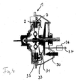
- FIG. 4 shows a clutch 1 according to the invention in a schematic, sectional view where the clutch plates are marked with 2, 3 and where the clutch 1 is in an open position. This is the result of a force generated for example by a spring mechanism or a spring 30 that is pressing against a lever 31 which acts on a cup spring 33.
- the cup spring 33 acts against the fixed bearing 35 and gives way to the clutch plates 2, 3.
- the actuator 36 applies a force in the direction 37 on the lever 31, and the cup spring 33 thus presses against the clutch plates 2, 3 and presses them together.
- the invention ensures that in a non operational condition of an actuator 36, the spring 30 keeps the clutch in an open position or at least a non closed position.
- a motor can be launched by a starter even if the transmission cannot be operated and a gear is engaged.
Landscapes
- Engineering & Computer Science (AREA)
- General Engineering & Computer Science (AREA)
- Mechanical Engineering (AREA)
- Physics & Mathematics (AREA)
- Fluid Mechanics (AREA)
- Gear-Shifting Mechanisms (AREA)
- Control Of Driving Devices And Active Controlling Of Vehicle (AREA)
- Hybrid Electric Vehicles (AREA)
Abstract
Description
- The present invention refers to the technical field of automotive technology and more specifically to the field of drives for vehicles.
- For decades now for cars and other vehicles drive systems with motors, transmission systems and clutches are state of the art. Transmission systems allow for keeping motor velocity in an appropriate range and at the same time transferring rotation to the wheels in order to achieve the wanted vehicle velocity. For shifting gears mechanical clutches, h-pattern shifters and mechanical transmissions are well known.
- In the mean time instead of manually actuated clutches and conventional manual transmissions more and more automatically and semiautomatically actuated clutches and transmissions have been introduced. For example the clutch-by-wire technology allows for using a clutch pedal as actuator with an electrical sensor sensing the mechanical position and transmitting the position of the pedal to a control box that is electrically or hydraulically actuating a clutch unit.
- Similar techniques can be used for shifting of the gears that can be initiated by simply hitting buttons on the steering wheel or on the dashboard of a car.
- Sometimes problems occur with automatic systems, especially electrical systems, when the system does not work properly. The conventional clutch for example requires to apply a mechanical force to be opened and otherwise is kept closed. This means for example for a vehicle with a clutch by wire system and a by-wire operated stepped transmission, if the control and actuation system do not work, the vehicle itself cannot be pulled or pushed off the street without the motor running because the motor and wheels cannot be separated.
- For this case special mechanical unlock mechanisms have to be provided or special safety features like redundancy have to be provided for automatic systems.
- The present invention seeks to solve these problems in a simple way with a simple construction. It can be used with advantage for vehicles with automatic or semiautomatic transmission systems, however it can also be used with conventional systems.
- The vehicle drive system according to the present invention offers special advantages because without any activity from an automatic control system of the vehicle the clutch is held in a position different from the closed position. Therefore, in case of a failure of the control and actuation system it is possible to move the vehicle even if the motor is not running and if a gear of the transmission system is engaged because the transmission system is not mechanically connected to the motor of the vehicle. It may also be possible to change the gear as long as the clutch is not closed which is the case as long as any automatic control system is not working properly.
- The invention has special benefits for the use in vehicles with by-wire shifted transmission systems or automated manual transmission systems. With these systems, a change or disengagement of the gear is not possible as long as the automatic control system of the vehicle is not working. Thus the only way of moving the vehicle is with a gear engaged but the clutch disengaged, at least partially.
- The system according to the present invention can also be used with advantage in systems with a so called clutch-by-wire system. As soon as the electrical control unit of the clutch fails to work properly, a mechanical elastic forces system makes sure that the clutch is brought into a position where freedom of action is guaranteed.
- The invention can be used in a vehicle with a single clutch system as well as in vehicles with dual clutch systems.
- In the conventional technique due to the normally closed clutch the transmission system with a gear engaged is often used as a park lock system. As this system does not work with a normally open clutch the invention can well be combined with an additional park lock system that mechanically blocks the transmission system in a parking status. This park lock system can automatically be activated when the vehicle is not moving, the clutch is in a position different from the closed position and, for example, the hand brake is operated.
- However it should be ensured that the park lock system can be unlocked manually.
- The inventive system of a normally open clutch or at least a normally not closed clutch may be realised by an elastic force mechanism, for example a spring acting against movement of the clutch into the closed position.
- This way the automatic control system will, when the system is operating properly, act against the spring force and overcome it to draw the clutch into the closed position and keep it there to guarantee maximum torque transfer. As soon as the automatic system fails, the clutch is drawn into a non closed position by the spring. If the clutch is in a not fully open position, it can be opened fully by the clutch pedal.
- For this mechanism an over center spring and a lever can well be used in a range close to the mechanical dead point where a force developed by the spring is relatively small.
- According to the description below the figures of the drawing show:
- figure 1
- a schematic view of a vehicle drive system according to the invention,
- figure 2
- a diagram where the force of the elastic force mechanism is shown versus the travel path of the clutch pedal,
- figure 3
- the clutch in an enlarged view and
- figure 4
- a conventional clutch in a sectional view.
-
Figure 1 shows a clutch 1 with twocircular plates plates - A
clutch pedal 8 is shown schematically at the end of a lever 9 which is pivotably mounted at apivoting point 10. When pressing theclutch pedal 8 in direction of anarrow 11, the lever 9 presses against ablock 12 that is mounted on acircular plate 13. Thecircular plate 13 is mounted on a bearing 14 rotatably. Theblock 12 is connected with anactuating arm 15 that is in contact with theplate 3 of the clutch 1 and serves to open the clutch 1 by pressing in the direction of an arrow 16. - An elastic mechanism is provided at the
plate 13 with a spring 17 that has the effect to turn theplate 13 clockwise as the force acting on theplate 13 is in the direction of the arrow 17a. Thus, the spring 17 serves to keep the clutch 1 open. Further opening can be initiated by theclutch pedal 8. Thepedal spring 18 generates a well known characteristic of a counter force for theclutch pedal 8. - Under normal operating conditions, the
automatic control system 19 of the vehicle activates theactuator 20 that presses theclutch plate 3 in the direction of an arrow 21 against theother clutch plate 2 to bring the clutch 1 in operational position where the twoclutch plates actuator 20 overcomes the force applied by the spring 17. - As described, when the
automatic control system 19 of the vehicle does not work properly, theactuator 20 does not apply any force against theclutch plate 3 and the clutch 1 remains open. So a vehicle can be pushed or pulled because the wheels can roll without moving the motor 6. - To ensure appropriate parking conditions, a park lock system 22 controls a
park lock actuator 23 that can apply a force against the clutch plates to close the clutch 1. The park lock system 22 can be constructed in a way that it can be operated manually. -
Figure 2 shows in acurve 24 on the vertical axis the force F that is transferred by theoperating lever 15 when theactuator 20 is operating and theplate 13 is rotated counterclockwise. When thefixing point 25 travels counterclockwise and is in one straight line with the central bearing 14 of theplate 13 and the spring 17, the spring mechanism is at a dead point where the acting force transferred from the spring 17 to the clutch 1 is zero, in the diagram ofFig. 2 this point is marked with s3. Before reaching that point in the range between s1 and s2 the mechanism can be operated properly, the clutch 1 is kept open by the spring 17 and theactuator 20 has only to overcome a small over center force in order to close the clutch 1 under normal operating conditions. -
Figure 3 shows an enlarged view of twoclutch plates frictional surface layers second clutch plate 3, in a closed position. -
Figure 4 shows a clutch 1 according to the invention in a schematic, sectional view where the clutch plates are marked with 2, 3 and where the clutch 1 is in an open position. This is the result of a force generated for example by a spring mechanism or aspring 30 that is pressing against alever 31 which acts on acup spring 33. Thecup spring 33 acts against the fixedbearing 35 and gives way to theclutch plates - When the clutch 1 has to be closed, the
actuator 36 applies a force in the direction 37 on thelever 31, and thecup spring 33 thus presses against theclutch plates - The invention ensures that in a non operational condition of an
actuator 36, thespring 30 keeps the clutch in an open position or at least a non closed position. - So, a vehicle with a gear engaged and a non manual transmission can be pushed or pulled without the motor 6 running.
- Also, a motor can be launched by a starter even if the transmission cannot be operated and a gear is engaged.
-
- 1
- clutch
- 2, 3
- plate
- 4, 5
- axle
- 6
- motor
- 7
- transmission
- 8
- clutch pedal
- 9
- lever
- 10
- pivoting point
- 11
- arrow
- 12
- block
- 13
- circular plate
- 14
- bearing
- 15
- actuating arm
- 16
- arrow
- 17
- spring
- 17a
- arrwor
- 18
- pedal spring
- 19
- automatic control system
- 20
- actuator
- 21
- arrow
- 22
- park lock system
- 23
- park lock actuator
- 24
- curve
- 30
- spring
- 31
- lever
- 33
- cup spring
- 35
- fixed bearing
- 36
- actuator
- 37
- direction
Claims (12)
- Vehicle drive system, comprising a motor (6), a transmission system and a clutch (1),
wherein the clutch (1) comprises a closed position and an open position, wherein the clutch (1) in the closed position is transferring torque between said motor (6) and said transmission system and wherein said clutch (1) in the open position is not transferring substantial torque between said motor (6) and the transmission system, wherein the transmission system comprises a transmission and a shifting system for engaging and disengaging gears,
wherein the movement of the clutch (1) from the closed position to the open position requires support from an automatic control system (19) of the vehicle and wherein an elastic force system is provided which mechanically keeps the clutch (1) in a position different from the closed position as long as the automatic control system (19) is inactive. - Vehicle drive system according to claim 1,
wherein the transmission system comprises a shifting system and wherein the shifting system for a shift action requires support from the automatic control system (19) of the vehicle. - Vehicle drive system according to any of the proceeding claims,
wherein the transmission system comprises a by -wire shifting system. - Vehicle drive system according to any of the proceeding claims,
wherein the transmission system is an automatic transmission or an automatically supported manual transmission. - Vehicle drive system according to any of the proceeding claims,
wherein a single clutch system is provided. - Vehicle drive system according to any of the proceeding claims,
wherein a dual clutch system is provided. - Vehicle drive system according to any of the proceeding claims,
wherein a park lock system (22) is provided that mechanically blocks the transmission system in a parking status. - Vehicle drive system according to claim 7,
wherein said park lock system (22) is automatically activated when the vehicle is not moving and the position of the clutch (1) is in a position different from the closed position. - Vehicle drive system according to claim 8,
wherein the park lock system (11) can be unlocked manually. - Vehicle drive system according to any of the proceeding claims,
wherein the elastic force mechanism comprises a spring acting against a movement of the clutch (1) into the closed position. - Vehicle drive system according to claim 10,
wherein the spring is linked to a dead point mechanism wherein the resisting force of the spring against movement of the clutch (1) into the closed position is decreasing when the clutch (1) approaches the closed position. - Vehicle drive system according to claim 10,
wherein said spring is a disc spring or a cup spring.
Priority Applications (2)
| Application Number | Priority Date | Filing Date | Title |
|---|---|---|---|
| AT08020841T ATE514009T1 (en) | 2008-12-01 | 2008-12-01 | VEHICLE DRIVE SYSTEM WITH TRANSMISSION SYSTEM AND CLUTCH |
| EP08020841A EP2192318B1 (en) | 2008-12-01 | 2008-12-01 | Vehicle drive system with a transmission system and a clutch |
Applications Claiming Priority (1)
| Application Number | Priority Date | Filing Date | Title |
|---|---|---|---|
| EP08020841A EP2192318B1 (en) | 2008-12-01 | 2008-12-01 | Vehicle drive system with a transmission system and a clutch |
Publications (2)
| Publication Number | Publication Date |
|---|---|
| EP2192318A1 true EP2192318A1 (en) | 2010-06-02 |
| EP2192318B1 EP2192318B1 (en) | 2011-06-22 |
Family
ID=40547977
Family Applications (1)
| Application Number | Title | Priority Date | Filing Date |
|---|---|---|---|
| EP08020841A Not-in-force EP2192318B1 (en) | 2008-12-01 | 2008-12-01 | Vehicle drive system with a transmission system and a clutch |
Country Status (2)
| Country | Link |
|---|---|
| EP (1) | EP2192318B1 (en) |
| AT (1) | ATE514009T1 (en) |
Citations (3)
| Publication number | Priority date | Publication date | Assignee | Title |
|---|---|---|---|---|
| EP1455107A2 (en) * | 2003-03-03 | 2004-09-08 | LuK Lamellen und Kupplungsbau Beteiligungs KG | Drive train |
| DE102006010248A1 (en) * | 2006-03-02 | 2007-09-06 | Zf Friedrichshafen Ag | Electric motor with linkage system is used as an actuator for the clutch mechanism in an automobile |
| DE102006035134A1 (en) * | 2006-07-29 | 2008-01-31 | Zf Friedrichshafen Ag | coupling system |
-
2008
- 2008-12-01 AT AT08020841T patent/ATE514009T1/en not_active IP Right Cessation
- 2008-12-01 EP EP08020841A patent/EP2192318B1/en not_active Not-in-force
Patent Citations (3)
| Publication number | Priority date | Publication date | Assignee | Title |
|---|---|---|---|---|
| EP1455107A2 (en) * | 2003-03-03 | 2004-09-08 | LuK Lamellen und Kupplungsbau Beteiligungs KG | Drive train |
| DE102006010248A1 (en) * | 2006-03-02 | 2007-09-06 | Zf Friedrichshafen Ag | Electric motor with linkage system is used as an actuator for the clutch mechanism in an automobile |
| DE102006035134A1 (en) * | 2006-07-29 | 2008-01-31 | Zf Friedrichshafen Ag | coupling system |
Also Published As
| Publication number | Publication date |
|---|---|
| ATE514009T1 (en) | 2011-07-15 |
| EP2192318B1 (en) | 2011-06-22 |
Similar Documents
| Publication | Publication Date | Title |
|---|---|---|
| KR100961026B1 (en) | Vehicle parking control system | |
| CN106545650B (en) | Method for disengaging parking lock of double clutch transmission of motor vehicle | |
| JP3940266B2 (en) | Hydraulic mechanism for clutch operating system | |
| US6629589B2 (en) | Vehicle clutch driving device and gear shifting device of vehicle transmission | |
| US6286633B1 (en) | Parking brake for an automatic transmission mechanism | |
| CN103231697A (en) | Interlocking structure of automobile braking system | |
| US6856880B2 (en) | Automatic shift controller for a vehicle | |
| CN106795922A (en) | Clutch apparatus, motor vehicle for motor vehicle and the method for running the clutch apparatus for motor vehicle | |
| US20230043711A1 (en) | Manual transmission lock for parking assistance | |
| CN115126866A (en) | Method and system for parking mechanism | |
| CN118251559A (en) | Motor vehicle with a coupling transmission and a functionally reliable parking lock | |
| CN115107415B (en) | Electric drive axle for a motor vehicle with a central actuator device | |
| CN100381312C (en) | car parking system | |
| KR20040066736A (en) | Automated Transmission Systems | |
| US20240229930A1 (en) | Motor Vehicle Having a Coupling Mechanism and a Parking Lock Device | |
| EP2192318B1 (en) | Vehicle drive system with a transmission system and a clutch | |
| CN103032564B (en) | For operation equipment and the controlling method thereof of the automatic double-clutch speed changer of motor vehicle | |
| US11255428B2 (en) | Securing device for securing a stationary state of an electric vehicle | |
| US20190049000A1 (en) | System to control a manual transmission | |
| CN105659008B (en) | Operating device with master cylinder actuatable by means of a shift drum for actuating a clutch | |
| KR101060036B1 (en) | Transfer case | |
| JP3618039B2 (en) | Work vehicle | |
| JP3286338B2 (en) | Brake mechanism for traveling vehicles | |
| JPH0310112Y2 (en) | ||
| JPS5921953Y2 (en) | clutch switching device |
Legal Events
| Date | Code | Title | Description |
|---|---|---|---|
| PUAI | Public reference made under article 153(3) epc to a published international application that has entered the european phase |
Free format text: ORIGINAL CODE: 0009012 |
|
| AK | Designated contracting states |
Kind code of ref document: A1 Designated state(s): AT BE BG CH CY CZ DE DK EE ES FI FR GB GR HR HU IE IS IT LI LT LU LV MC MT NL NO PL PT RO SE SI SK TR |
|
| AX | Request for extension of the european patent |
Extension state: AL BA MK RS |
|
| 17P | Request for examination filed |
Effective date: 20101202 |
|
| AKX | Designation fees paid |
Designated state(s): AT BE BG CH CY CZ DE DK EE ES FI FR GB GR HR HU IE IS IT LI LT LU LV MC MT NL NO PL PT RO SE SI SK TR |
|
| GRAP | Despatch of communication of intention to grant a patent |
Free format text: ORIGINAL CODE: EPIDOSNIGR1 |
|
| GRAS | Grant fee paid |
Free format text: ORIGINAL CODE: EPIDOSNIGR3 |
|
| GRAA | (expected) grant |
Free format text: ORIGINAL CODE: 0009210 |
|
| AK | Designated contracting states |
Kind code of ref document: B1 Designated state(s): AT BE BG CH CY CZ DE DK EE ES FI FR GB GR HR HU IE IS IT LI LT LU LV MC MT NL NO PL PT RO SE SI SK TR |
|
| REG | Reference to a national code |
Ref country code: GB Ref legal event code: FG4D |
|
| REG | Reference to a national code |
Ref country code: CH Ref legal event code: EP |
|
| REG | Reference to a national code |
Ref country code: CH Ref legal event code: PFA Owner name: GM GLOBAL TECHNOLOGY OPERATIONS LLC Free format text: GM GLOBAL TECHNOLOGY OPERATIONS LLC#300 RENAISSANCE CENTER#DETROIT, MI 48265-3000 (US) -TRANSFER TO- GM GLOBAL TECHNOLOGY OPERATIONS LLC#300 RENAISSANCE CENTER#DETROIT, MI 48265-3000 (US) |
|
| REG | Reference to a national code |
Ref country code: IE Ref legal event code: FG4D |
|
| RAP2 | Party data changed (patent owner data changed or rights of a patent transferred) |
Owner name: GM GLOBAL TECHNOLOGY OPERATIONS LLC |
|
| REG | Reference to a national code |
Ref country code: DE Ref legal event code: R096 Ref document number: 602008007732 Country of ref document: DE Effective date: 20110804 |
|
| REG | Reference to a national code |
Ref country code: NL Ref legal event code: VDEP Effective date: 20110622 |
|
| PG25 | Lapsed in a contracting state [announced via postgrant information from national office to epo] |
Ref country code: LT Free format text: LAPSE BECAUSE OF FAILURE TO SUBMIT A TRANSLATION OF THE DESCRIPTION OR TO PAY THE FEE WITHIN THE PRESCRIBED TIME-LIMIT Effective date: 20110622 Ref country code: SE Free format text: LAPSE BECAUSE OF FAILURE TO SUBMIT A TRANSLATION OF THE DESCRIPTION OR TO PAY THE FEE WITHIN THE PRESCRIBED TIME-LIMIT Effective date: 20110622 Ref country code: HR Free format text: LAPSE BECAUSE OF FAILURE TO SUBMIT A TRANSLATION OF THE DESCRIPTION OR TO PAY THE FEE WITHIN THE PRESCRIBED TIME-LIMIT Effective date: 20110622 Ref country code: NO Free format text: LAPSE BECAUSE OF FAILURE TO SUBMIT A TRANSLATION OF THE DESCRIPTION OR TO PAY THE FEE WITHIN THE PRESCRIBED TIME-LIMIT Effective date: 20110922 |
|
| PG25 | Lapsed in a contracting state [announced via postgrant information from national office to epo] |
Ref country code: LV Free format text: LAPSE BECAUSE OF FAILURE TO SUBMIT A TRANSLATION OF THE DESCRIPTION OR TO PAY THE FEE WITHIN THE PRESCRIBED TIME-LIMIT Effective date: 20110622 Ref country code: FI Free format text: LAPSE BECAUSE OF FAILURE TO SUBMIT A TRANSLATION OF THE DESCRIPTION OR TO PAY THE FEE WITHIN THE PRESCRIBED TIME-LIMIT Effective date: 20110622 Ref country code: CY Free format text: LAPSE BECAUSE OF FAILURE TO SUBMIT A TRANSLATION OF THE DESCRIPTION OR TO PAY THE FEE WITHIN THE PRESCRIBED TIME-LIMIT Effective date: 20110622 Ref country code: SI Free format text: LAPSE BECAUSE OF FAILURE TO SUBMIT A TRANSLATION OF THE DESCRIPTION OR TO PAY THE FEE WITHIN THE PRESCRIBED TIME-LIMIT Effective date: 20110622 Ref country code: AT Free format text: LAPSE BECAUSE OF FAILURE TO SUBMIT A TRANSLATION OF THE DESCRIPTION OR TO PAY THE FEE WITHIN THE PRESCRIBED TIME-LIMIT Effective date: 20110622 Ref country code: GR Free format text: LAPSE BECAUSE OF FAILURE TO SUBMIT A TRANSLATION OF THE DESCRIPTION OR TO PAY THE FEE WITHIN THE PRESCRIBED TIME-LIMIT Effective date: 20110923 |
|
| PG25 | Lapsed in a contracting state [announced via postgrant information from national office to epo] |
Ref country code: NL Free format text: LAPSE BECAUSE OF FAILURE TO SUBMIT A TRANSLATION OF THE DESCRIPTION OR TO PAY THE FEE WITHIN THE PRESCRIBED TIME-LIMIT Effective date: 20110622 Ref country code: BE Free format text: LAPSE BECAUSE OF FAILURE TO SUBMIT A TRANSLATION OF THE DESCRIPTION OR TO PAY THE FEE WITHIN THE PRESCRIBED TIME-LIMIT Effective date: 20110622 |
|
| PG25 | Lapsed in a contracting state [announced via postgrant information from national office to epo] |
Ref country code: CZ Free format text: LAPSE BECAUSE OF FAILURE TO SUBMIT A TRANSLATION OF THE DESCRIPTION OR TO PAY THE FEE WITHIN THE PRESCRIBED TIME-LIMIT Effective date: 20110622 Ref country code: IS Free format text: LAPSE BECAUSE OF FAILURE TO SUBMIT A TRANSLATION OF THE DESCRIPTION OR TO PAY THE FEE WITHIN THE PRESCRIBED TIME-LIMIT Effective date: 20111022 Ref country code: EE Free format text: LAPSE BECAUSE OF FAILURE TO SUBMIT A TRANSLATION OF THE DESCRIPTION OR TO PAY THE FEE WITHIN THE PRESCRIBED TIME-LIMIT Effective date: 20110622 Ref country code: PT Free format text: LAPSE BECAUSE OF FAILURE TO SUBMIT A TRANSLATION OF THE DESCRIPTION OR TO PAY THE FEE WITHIN THE PRESCRIBED TIME-LIMIT Effective date: 20111024 |
|
| PG25 | Lapsed in a contracting state [announced via postgrant information from national office to epo] |
Ref country code: RO Free format text: LAPSE BECAUSE OF FAILURE TO SUBMIT A TRANSLATION OF THE DESCRIPTION OR TO PAY THE FEE WITHIN THE PRESCRIBED TIME-LIMIT Effective date: 20110622 Ref country code: SK Free format text: LAPSE BECAUSE OF FAILURE TO SUBMIT A TRANSLATION OF THE DESCRIPTION OR TO PAY THE FEE WITHIN THE PRESCRIBED TIME-LIMIT Effective date: 20110622 Ref country code: PL Free format text: LAPSE BECAUSE OF FAILURE TO SUBMIT A TRANSLATION OF THE DESCRIPTION OR TO PAY THE FEE WITHIN THE PRESCRIBED TIME-LIMIT Effective date: 20110622 |
|
| PLBE | No opposition filed within time limit |
Free format text: ORIGINAL CODE: 0009261 |
|
| STAA | Information on the status of an ep patent application or granted ep patent |
Free format text: STATUS: NO OPPOSITION FILED WITHIN TIME LIMIT |
|
| 26N | No opposition filed |
Effective date: 20120323 |
|
| PG25 | Lapsed in a contracting state [announced via postgrant information from national office to epo] |
Ref country code: IT Free format text: LAPSE BECAUSE OF FAILURE TO SUBMIT A TRANSLATION OF THE DESCRIPTION OR TO PAY THE FEE WITHIN THE PRESCRIBED TIME-LIMIT Effective date: 20110622 |
|
| PG25 | Lapsed in a contracting state [announced via postgrant information from national office to epo] |
Ref country code: DK Free format text: LAPSE BECAUSE OF FAILURE TO SUBMIT A TRANSLATION OF THE DESCRIPTION OR TO PAY THE FEE WITHIN THE PRESCRIBED TIME-LIMIT Effective date: 20110622 |
|
| REG | Reference to a national code |
Ref country code: DE Ref legal event code: R097 Ref document number: 602008007732 Country of ref document: DE Effective date: 20120323 |
|
| PG25 | Lapsed in a contracting state [announced via postgrant information from national office to epo] |
Ref country code: MC Free format text: LAPSE BECAUSE OF NON-PAYMENT OF DUE FEES Effective date: 20111231 |
|
| REG | Reference to a national code |
Ref country code: IE Ref legal event code: MM4A |
|
| PG25 | Lapsed in a contracting state [announced via postgrant information from national office to epo] |
Ref country code: IE Free format text: LAPSE BECAUSE OF NON-PAYMENT OF DUE FEES Effective date: 20111201 |
|
| PG25 | Lapsed in a contracting state [announced via postgrant information from national office to epo] |
Ref country code: MT Free format text: LAPSE BECAUSE OF FAILURE TO SUBMIT A TRANSLATION OF THE DESCRIPTION OR TO PAY THE FEE WITHIN THE PRESCRIBED TIME-LIMIT Effective date: 20110622 |
|
| PG25 | Lapsed in a contracting state [announced via postgrant information from national office to epo] |
Ref country code: ES Free format text: LAPSE BECAUSE OF FAILURE TO SUBMIT A TRANSLATION OF THE DESCRIPTION OR TO PAY THE FEE WITHIN THE PRESCRIBED TIME-LIMIT Effective date: 20111003 |
|
| PG25 | Lapsed in a contracting state [announced via postgrant information from national office to epo] |
Ref country code: LU Free format text: LAPSE BECAUSE OF NON-PAYMENT OF DUE FEES Effective date: 20111201 |
|
| PG25 | Lapsed in a contracting state [announced via postgrant information from national office to epo] |
Ref country code: BG Free format text: LAPSE BECAUSE OF FAILURE TO SUBMIT A TRANSLATION OF THE DESCRIPTION OR TO PAY THE FEE WITHIN THE PRESCRIBED TIME-LIMIT Effective date: 20110922 |
|
| REG | Reference to a national code |
Ref country code: CH Ref legal event code: PL |
|
| PG25 | Lapsed in a contracting state [announced via postgrant information from national office to epo] |
Ref country code: TR Free format text: LAPSE BECAUSE OF FAILURE TO SUBMIT A TRANSLATION OF THE DESCRIPTION OR TO PAY THE FEE WITHIN THE PRESCRIBED TIME-LIMIT Effective date: 20110622 |
|
| PG25 | Lapsed in a contracting state [announced via postgrant information from national office to epo] |
Ref country code: CH Free format text: LAPSE BECAUSE OF NON-PAYMENT OF DUE FEES Effective date: 20121231 Ref country code: HU Free format text: LAPSE BECAUSE OF FAILURE TO SUBMIT A TRANSLATION OF THE DESCRIPTION OR TO PAY THE FEE WITHIN THE PRESCRIBED TIME-LIMIT Effective date: 20110622 Ref country code: LI Free format text: LAPSE BECAUSE OF NON-PAYMENT OF DUE FEES Effective date: 20121231 |
|
| REG | Reference to a national code |
Ref country code: FR Ref legal event code: PLFP Year of fee payment: 8 |
|
| PGFP | Annual fee paid to national office [announced via postgrant information from national office to epo] |
Ref country code: GB Payment date: 20151125 Year of fee payment: 8 |
|
| PGFP | Annual fee paid to national office [announced via postgrant information from national office to epo] |
Ref country code: FR Payment date: 20151110 Year of fee payment: 8 |
|
| PGFP | Annual fee paid to national office [announced via postgrant information from national office to epo] |
Ref country code: DE Payment date: 20161123 Year of fee payment: 9 |
|
| GBPC | Gb: european patent ceased through non-payment of renewal fee |
Effective date: 20161201 |
|
| REG | Reference to a national code |
Ref country code: FR Ref legal event code: ST Effective date: 20170831 |
|
| PG25 | Lapsed in a contracting state [announced via postgrant information from national office to epo] |
Ref country code: FR Free format text: LAPSE BECAUSE OF NON-PAYMENT OF DUE FEES Effective date: 20170102 |
|
| PG25 | Lapsed in a contracting state [announced via postgrant information from national office to epo] |
Ref country code: GB Free format text: LAPSE BECAUSE OF NON-PAYMENT OF DUE FEES Effective date: 20161201 |
|
| REG | Reference to a national code |
Ref country code: DE Ref legal event code: R119 Ref document number: 602008007732 Country of ref document: DE |
|
| PG25 | Lapsed in a contracting state [announced via postgrant information from national office to epo] |
Ref country code: DE Free format text: LAPSE BECAUSE OF NON-PAYMENT OF DUE FEES Effective date: 20180703 |