EP2192263A1 - Method for monitoring cement plugs - Google Patents
Method for monitoring cement plugs Download PDFInfo
- Publication number
- EP2192263A1 EP2192263A1 EP08170140A EP08170140A EP2192263A1 EP 2192263 A1 EP2192263 A1 EP 2192263A1 EP 08170140 A EP08170140 A EP 08170140A EP 08170140 A EP08170140 A EP 08170140A EP 2192263 A1 EP2192263 A1 EP 2192263A1
- Authority
- EP
- European Patent Office
- Prior art keywords
- cable
- cement
- sensor
- cement plug
- plug
- Prior art date
- Legal status (The legal status is an assumption and is not a legal conclusion. Google has not performed a legal analysis and makes no representation as to the accuracy of the status listed.)
- Withdrawn
Links
Images
Classifications
-
- E—FIXED CONSTRUCTIONS
- E21—EARTH OR ROCK DRILLING; MINING
- E21B—EARTH OR ROCK DRILLING; OBTAINING OIL, GAS, WATER, SOLUBLE OR MELTABLE MATERIALS OR A SLURRY OF MINERALS FROM WELLS
- E21B33/00—Sealing or packing boreholes or wells
- E21B33/10—Sealing or packing boreholes or wells in the borehole
- E21B33/13—Methods or devices for cementing, for plugging holes, crevices or the like
- E21B33/134—Bridging plugs
-
- E—FIXED CONSTRUCTIONS
- E21—EARTH OR ROCK DRILLING; MINING
- E21B—EARTH OR ROCK DRILLING; OBTAINING OIL, GAS, WATER, SOLUBLE OR MELTABLE MATERIALS OR A SLURRY OF MINERALS FROM WELLS
- E21B47/00—Survey of boreholes or wells
- E21B47/005—Monitoring or checking of cementation quality or level
-
- E—FIXED CONSTRUCTIONS
- E21—EARTH OR ROCK DRILLING; MINING
- E21B—EARTH OR ROCK DRILLING; OBTAINING OIL, GAS, WATER, SOLUBLE OR MELTABLE MATERIALS OR A SLURRY OF MINERALS FROM WELLS
- E21B47/00—Survey of boreholes or wells
- E21B47/12—Means for transmitting measuring-signals or control signals from the well to the surface, or from the surface to the well, e.g. for logging while drilling
Definitions
- This invention relates to a method for completing a well.
- the invention relates to a method for determining the parameters of a cement plug in a wellbore.
- the cement plug is typically constructed by pumping a small amount of cement slurry down a drill pipe where it later sets solid to form a plug. Drilling operations can resume when the cement plug has set and developed enough strength to fulfil its objective.
- a viscous pill generally composed of a dense viscous bentonite and sodium silicate mixture, is spotted in the borehole, to support the cement plug.
- a variation on this method includes the use of an "umbrella" device placed under the drill pipe to support the plug instead of the pill.
- an expanding basket with a membrane over it can be inserted into the wellbore in front of a dart that can be pumped down a drill pipe. The basket expands below the drill pipe on top of which cement is placed.
- Determining whether the plug setting is successful at all i.e. if the cement is hard enough to side track against and/or if the cement is hard enough to pressure test against, adds significant rig time due to the waiting on cement. Also cement plugs are only placed through drill bits in certain well control situations, and all other situations require tripping out. Thereby requiring installation of the production tube at the bottom of the string, running in and placing the plug. If the cost of tripping out is very high the string may be left in place during the waiting period and then used to tag the plug, in this case a new plug may be placed immediately. Otherwise the driller will trip out and trip back in the drill bit. Once the waiting time is over the driller will try to tag the cement.
- a first aspect of the invention provides a method of monitoring the parameters of a cement plug in a wellbore comprising; pumping a cement slurry down a wellbore; providing a cable through the cement plug before the cement plug sets, wherein the cable comprises a sensor for monitoring parameters of the cement plug; locating the sensor in the proximity of the bottom of the cement plug; operating the sensor to measure a parameters of the cement plug; and transmitting information regarding the measurement to the surface.
- the method comprises locating the sensor below the cement plug in the wellbore.
- the lower sensor module is placed into the wellbore before pumping the cement slurry down the wellbore and the cable is attached to the sensor after the cement is pumped into the wellbore.
- the method comprises locating the sensor in the cement plug.
- the cable can also comprise an upper sensor module, wherein the method comprises deploying the cable into the cement plug such that the upper module is located in the proximity of the top of the cement plug.
- the method can comprise deploying the cable from the surface.
- the cable can be deployed from the surface using fluid pumped through a placement conduit.
- a weight can be provided on the end of the cable to assist the deployment of the cable.
- the method comprises deploying the cable from the placement conduit used to place the cement plug.
- the cable can be stored on a tubular element detachable from the end of the placement conduit, wherein the method comprises detaching the tubular element from the placement conduit after the cement is placed and removing the placement conduit from the wellbore, such that the tubular element remains in the cement.
- Mechanical means can be provided in the wellbore to assist the deployment of the cable.
- Mechanical means such as vibrators, propellers, pumps, wheels and /or tracks can be used.
- the cable comprises a fibre optic cable and/or an electrical cable.
- the sensors are used to determine the length of the cement plug, evaluate the solidity of the cement plug, to determine the location of the plug, and/or to evaluate the setting of the cement plug.
- the sensor may be a temperature sensor, pressure sensor, electrical conductivity sensor, vibration sensor, accelerometer, impedance sensor, or other sensor, and/or is capable of making distributed vibration measurements.
- the method can further comprise locating a signally apparatus at the top of the cement plug; and transmitting information regarding the measurement to the surface via the signalling device.
- the signalling device can comprise an acoustic pressure source.
- the cable is provided during pumping of the cement slurry.
- the cable can be provided into the wellbore after pumping of the cement slurry.
- the invention comprises deploying a cable into a cement plug before the cement has set to take measurements for determining properties of the cement plug.
- the cement slurry may be placed by any known method for forming a cement plug in a wellbore. Cement can be pumped down a cement placement tube to a desired location. Once the cement has been placed the cable is deployed into the cement plug prior to the setting of the plug. After the cement has set at least a portion of the cable will be encased in the set cement.
- the cable comprises sensors to monitor parameters of the cement. The presence of the sensors allows information about the plug to be obtained. As the properties of the cement change with time as it sets, the operator can follow in real time the actual properties of the cement plug. This enables the operator to make timely decisions based on the measurements made, on when further wellbore operations can be resumed, thereby minimising unproductive time.
- Information that can be obtained includes information on the location of the plug, the dimensions of the plug, setting state of the plug, identification of channelling occurring in the plug.
- the information obtained can be used to determine when the cement plug has set sufficiently to enable further wellbore operations to begin i.e. if the cement is hard enough to allow side tracking to begin.
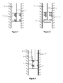
- Figure 1 shows a first embodiment of the invention.
- the cable 1 is deployed into the cement plug 2 after the placement of the cement plug in the wellbore 3 such that a sensor is located at the bottom of the cement plug at the interface of the cement plug and well fluid and a portion of the cable extends along a substantial length of the plug.
- the cable can be deployed into the cement plug during placement of the cement in the wellbore.
- the cable can be deployed from the surface using fluid pumped through the placement conduit.
- a weight can be attached to the end of the cable to assist the deployment of the cable.
- the end of the placement conduit can be provided with mechanical means such as vibrators, propellers, pumps, wheels and tracks etc, to assist the deployment of the cable, down the wellbore and into the cement plug.
- the cable is connected to a control system at the surface (not shown).
- the cable is deployed from the surface into the cement slurry before the cement has time to set.
- the cable extends from the surface through the cement slurry, such that a portion of the cable extends down the length of the cement plug.
- the cable comprises sensors to make measurements and is positioned in the cement plug so that a sensor is located at the bottom of the cement plug. Once positioned in the cement plug the sensors are then used to make measurements to determine properties of the cement plug.
- the measurements taken are transmitted up to the surface via the cable. Other telemetry methods can also be used to transmit the information to the surface.
- Figure 2 shows an alternative embodiment of the invention where the cable 1 is deployed from the surface through the cement plug 2 such that one end of the cable is attached to a lower sensor module 4 located in the wellbore 3 below the cement plug 2 while the other end of the cable 1 is connected to the control system (not shown) on the surface.
- the lower sensor module 4 may also be present in the wellbore 3 to support the cement plug. In some situations the module may be further located below the supporting pill, in which case the cable will pass through both the cement plug and pill.
- the lower sensor module may be located at or below the bottom of the cement plug.
- the sensor may be located on both sides of the lower boundary of the cement plug so only a part of the lower sensor module is located in the cement plug, with the rest of the sensor in contact with the wellbore fluid.
- the sensor module is constructed such that a density difference between the module and the plug and/or pill exists and allows the sensor to be located at the desired position relative to the cement plug.
- the lower sensor module can comprise a system to produce acoustic signals or pulses that propagate upward through the plug. Such signals can be tracked by the cable and will allow the length of the cement to be measured, and the location of interfaces, the quality of the cement/wellbore interfaces, and the setting of the cement, (by preventing the easy passage of such signals), to be determined.
- the cable can also comprise an upper sensor module to be located in the upper region of the cement plug.
- the upper sensor is preferably lighter than the cement but heavier than the mud, such that when the cable is deployed the module is positioned to sit at the interface of the cement plug and wellbore fluid.
- a storage system 5 comprising the cable 1 is attached to the lower end of the placement conduit 6.
- the placement conduit 6 is raised sufficiently to be clear of the top surface of the cement plug 2 and the cable 1 is deployed from the system 5 into the cement plug 2. Measurements are taken using the sensors of the cable 1.
- a communication wire (not shown) can connect the cable 1 to the surface and transmit information regarding the measurements taken of the cement plug, to the surface.
- the storage system may be conveyed to surface by removing the placement conduit, leaving the cable deployed along the length of the well. Alternatively, the storage system may be returned to surface by pumping fluid or by running wireline or slickline down the centre of the placement conduit to retrieve the system.
- a detachable tubular element is located on the end of the placement conduit.
- the tubular element is detached after the cement is placed and is left behind in the cement.
- the tubular element comprises the storage system for the cable such that the cable may be paid out as needed.
- the system can also be provided with an upper signalling module 7.
- the upper signalling module conveys information to the surface.
- the signalling module can comprise an acoustic pressure generating mechanism or alternatively the module may comprise a device that can change its acoustic properties sufficiently that such changes can be detected from surface when the device is interrogated by an acoustic wave from surface.
- the upper signalling module is particular suitable when the cable does no extend to the surface.
- the cable is a fibre optic cable, in particular a cable capable of making distributed vibration measurements.
- the cable may be formed from a plurality of cables and may be formed from both electrical and fibre optic cables.
- the cable can comprise all or part of the sensing system, for example an optical distributed temperature sensor.
- Other wave guide members or sensing strings may also be incorporated into the cable.
- the cable also acts as a communication wire, allowing information to be transmitted to and from the surface.
- the cable comprises both fibre optic and electrical cables, with the portion of the cable passing through the cement plug comprising the electrical cable having an attachment mechanism to connect to the optical fiber which leads to the surface.
- the electrical cable can be used as a sensor to detect the length of the cement plug and/or to evaluate the solidity of the plug. Measurements based on capacitance, resistance, conductivity, and stress area can be used to determine this information.
- the electrical cable can comprise electrodes for resistivity measurements at one or more locations in the plug, to help determine the setting length, location and/or to measure the solidity of the plug. Electromagnetic coils may also be located on the electrical cable, to also enable measurements such as resistivity measurements to help determine the setting length, location and solidity of the plug.
- the cable can comprise a one or more temperature sensing element such as distributed temperature sensing element.
- Guided wave radar may also be used along the cable to detect interfaces and/or the solidity of the cement.
- electronics in the cables may be activated any one of a number of methods; such as signals from down the cable, switching means before they are run into the hole, detecting the launching of the cable from a setting tool, pressure codes, dissolved elements etc.
- the sensors of the upper and lower sensor modules can also be activated by signals received down the cable to which the sensor modules are attached to. The signals may originate from the surface, or through the detection of actions occurring in the wellbore.
Landscapes
- Engineering & Computer Science (AREA)
- Mining & Mineral Resources (AREA)
- Geology (AREA)
- Life Sciences & Earth Sciences (AREA)
- Physics & Mathematics (AREA)
- Geochemistry & Mineralogy (AREA)
- Fluid Mechanics (AREA)
- Environmental & Geological Engineering (AREA)
- General Life Sciences & Earth Sciences (AREA)
- Geophysics (AREA)
- Remote Sensing (AREA)
- Quality & Reliability (AREA)
- On-Site Construction Work That Accompanies The Preparation And Application Of Concrete (AREA)
- Investigating Or Analyzing Materials By The Use Of Ultrasonic Waves (AREA)
- Preparation Of Clay, And Manufacture Of Mixtures Containing Clay Or Cement (AREA)
- Investigating Or Analyzing Materials By The Use Of Electric Means (AREA)
- Measuring Fluid Pressure (AREA)
Abstract
Description
- This invention relates to a method for completing a well. In particular the invention relates to a method for determining the parameters of a cement plug in a wellbore.
- After a well has been drilled there are often situations where the well must be sealed off. This is normally preformed with a cement plug. Other situations that may require sealing off an area of a well include: when a side track is needed during the drilling process; curing lost circulation during drilling; when a zone must be permanently isolated; and when a wellbore is going to be plugged and abandoned.
- The cement plug is typically constructed by pumping a small amount of cement slurry down a drill pipe where it later sets solid to form a plug. Drilling operations can resume when the cement plug has set and developed enough strength to fulfil its objective.
- In most situations the cement plug must be located some distance off the bottom of the wellbore in either a tubular or open hole section of the well. In order to achieve this, a viscous pill, generally composed of a dense viscous bentonite and sodium silicate mixture, is spotted in the borehole, to support the cement plug. A variation on this method includes the use of an "umbrella" device placed under the drill pipe to support the plug instead of the pill. Alternatively an expanding basket with a membrane over it can be inserted into the wellbore in front of a dart that can be pumped down a drill pipe. The basket expands below the drill pipe on top of which cement is placed.
- Problems with these methods are that they result in two heavy fluids stacked on top of a light fluid. One or both fluid interfaces can become unstable leading to inversion. The heavy fluid(s) move down one side of the borehole and the light fluid fluids move up the other side. Considerable mixing and contamination may then occur during the movement of the fluid. The channel formed prevents a pressure seal from being achieved and also significantly reduces the plug's mechanical strength. The mixing of the fluids can also destroy the mechanical strength of the plug. Cement plugs can fail up to third of the time. In lost circulation situations failure rates of cement plugs can be as high as 50%.
- Determining whether the plug setting is successful at all, i.e. if the cement is hard enough to side track against and/or if the cement is hard enough to pressure test against, adds significant rig time due to the waiting on cement. Also cement plugs are only placed through drill bits in certain well control situations, and all other situations require tripping out. Thereby requiring installation of the production tube at the bottom of the string, running in and placing the plug. If the cost of tripping out is very high the string may be left in place during the waiting period and then used to tag the plug, in this case a new plug may be placed immediately. Otherwise the driller will trip out and trip back in the drill bit. Once the waiting time is over the driller will try to tag the cement. If the cement is still soft, the driller will wait for longer. As there is great uncertainty about when it is safe to resume drilling operations, to mitigate the risk of resuming drilling operations too soon, it is common practice to wait extra time, typically 24 hours, before resuming drilling.
- Therefore it is an object of the invention to provide a method for monitoring a cement plug during in real time to determine the properties of the cement plug.
- A first aspect of the invention provides a method of monitoring the parameters of a cement plug in a wellbore comprising;
pumping a cement slurry down a wellbore;
providing a cable through the cement plug before the cement plug sets, wherein the cable comprises a sensor for monitoring parameters of the cement plug;
locating the sensor in the proximity of the bottom of the cement plug;
operating the sensor to measure a parameters of the cement plug; and
transmitting information regarding the measurement to the surface. - Preferably the method comprises locating the sensor below the cement plug in the wellbore. The lower sensor module is placed into the wellbore before pumping the cement slurry down the wellbore and the cable is attached to the sensor after the cement is pumped into the wellbore.
- In another embodiment the method comprises locating the sensor in the cement plug.
- The cable can also comprise an upper sensor module, wherein the method comprises deploying the cable into the cement plug such that the upper module is located in the proximity of the top of the cement plug.
- The method can comprise deploying the cable from the surface. The cable can be deployed from the surface using fluid pumped through a placement conduit. A weight can be provided on the end of the cable to assist the deployment of the cable.
- When the cable is stored on the placement conduit the method comprises deploying the cable from the placement conduit used to place the cement plug. The cable can be stored on a tubular element detachable from the end of the placement conduit, wherein the method comprises detaching the tubular element from the placement conduit after the cement is placed and removing the placement conduit from the wellbore, such that the tubular element remains in the cement.
- Mechanical means can be provided in the wellbore to assist the deployment of the cable. Mechanical means such as vibrators, propellers, pumps, wheels and /or tracks can be used.
- Preferably the cable comprises a fibre optic cable and/or an electrical cable.
- The sensors are used to determine the length of the cement plug, evaluate the solidity of the cement plug, to determine the location of the plug, and/or to evaluate the setting of the cement plug. The sensor may be a temperature sensor, pressure sensor, electrical conductivity sensor, vibration sensor, accelerometer, impedance sensor, or other sensor, and/or is capable of making distributed vibration measurements.
- The method can further comprise locating a signally apparatus at the top of the cement plug; and transmitting information regarding the measurement to the surface via the signalling device. The signalling device can comprise an acoustic pressure source.
- The cable is provided during pumping of the cement slurry. Alternatively the cable can be provided into the wellbore after pumping of the cement slurry.
-
-
Figure 1 shows a schematic view of the cable located in the cement plug; -
Figure 2 shows the deployment of the cable through the cement plug; -
Figure 3 shows deployment of the cable from the placement tube; and -
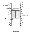
Figure 4 shows an embodiment of the deployment of the cable through the cement plug. - The invention comprises deploying a cable into a cement plug before the cement has set to take measurements for determining properties of the cement plug. The cement slurry may be placed by any known method for forming a cement plug in a wellbore. Cement can be pumped down a cement placement tube to a desired location. Once the cement has been placed the cable is deployed into the cement plug prior to the setting of the plug. After the cement has set at least a portion of the cable will be encased in the set cement. The cable comprises sensors to monitor parameters of the cement. The presence of the sensors allows information about the plug to be obtained. As the properties of the cement change with time as it sets, the operator can follow in real time the actual properties of the cement plug. This enables the operator to make timely decisions based on the measurements made, on when further wellbore operations can be resumed, thereby minimising unproductive time.
- Information that can be obtained includes information on the location of the plug, the dimensions of the plug, setting state of the plug, identification of channelling occurring in the plug. The information obtained can be used to determine when the cement plug has set sufficiently to enable further wellbore operations to begin i.e. if the cement is hard enough to allow side tracking to begin.
-
Figure 1 shows a first embodiment of the invention. Thecable 1 is deployed into thecement plug 2 after the placement of the cement plug in thewellbore 3 such that a sensor is located at the bottom of the cement plug at the interface of the cement plug and well fluid and a portion of the cable extends along a substantial length of the plug. Alternatively the cable can be deployed into the cement plug during placement of the cement in the wellbore. - The cable can be deployed from the surface using fluid pumped through the placement conduit. A weight can be attached to the end of the cable to assist the deployment of the cable. The end of the placement conduit can be provided with mechanical means such as vibrators, propellers, pumps, wheels and tracks etc, to assist the deployment of the cable, down the wellbore and into the cement plug.
- The cable is connected to a control system at the surface (not shown). The cable is deployed from the surface into the cement slurry before the cement has time to set. The cable extends from the surface through the cement slurry, such that a portion of the cable extends down the length of the cement plug. The cable comprises sensors to make measurements and is positioned in the cement plug so that a sensor is located at the bottom of the cement plug. Once positioned in the cement plug the sensors are then used to make measurements to determine properties of the cement plug. The measurements taken are transmitted up to the surface via the cable. Other telemetry methods can also be used to transmit the information to the surface.
-
Figure 2 shows an alternative embodiment of the invention where thecable 1 is deployed from the surface through thecement plug 2 such that one end of the cable is attached to a lower sensor module 4 located in thewellbore 3 below thecement plug 2 while the other end of thecable 1 is connected to the control system (not shown) on the surface. In addition to being a sensor the lower sensor module 4 may also be present in thewellbore 3 to support the cement plug. In some situations the module may be further located below the supporting pill, in which case the cable will pass through both the cement plug and pill. - The lower sensor module may be located at or below the bottom of the cement plug. Alternatively the sensor may be located on both sides of the lower boundary of the cement plug so only a part of the lower sensor module is located in the cement plug, with the rest of the sensor in contact with the wellbore fluid. In order to position the lower sensor module at or below the bottom of the cement plug, the sensor module is constructed such that a density difference between the module and the plug and/or pill exists and allows the sensor to be located at the desired position relative to the cement plug. The lower sensor module can comprise a system to produce acoustic signals or pulses that propagate upward through the plug. Such signals can be tracked by the cable and will allow the length of the cement to be measured, and the location of interfaces, the quality of the cement/wellbore interfaces, and the setting of the cement, (by preventing the easy passage of such signals), to be determined.
- The cable can also comprise an upper sensor module to be located in the upper region of the cement plug. The upper sensor is preferably lighter than the cement but heavier than the mud, such that when the cable is deployed the module is positioned to sit at the interface of the cement plug and wellbore fluid.
- As shown in
Figure 3 , in an alternative embodiment of the invention astorage system 5 comprising thecable 1 is attached to the lower end of theplacement conduit 6. Once the cement has been placed in the desired location theplacement conduit 6 is raised sufficiently to be clear of the top surface of thecement plug 2 and thecable 1 is deployed from thesystem 5 into thecement plug 2. Measurements are taken using the sensors of thecable 1. A communication wire (not shown) can connect thecable 1 to the surface and transmit information regarding the measurements taken of the cement plug, to the surface. The storage system may be conveyed to surface by removing the placement conduit, leaving the cable deployed along the length of the well. Alternatively, the storage system may be returned to surface by pumping fluid or by running wireline or slickline down the centre of the placement conduit to retrieve the system. - In a further embodiment a detachable tubular element is located on the end of the placement conduit. The tubular element is detached after the cement is placed and is left behind in the cement. The tubular element comprises the storage system for the cable such that the cable may be paid out as needed.
- With reference to
Figure 4 the system can also be provided with anupper signalling module 7. The upper signalling module conveys information to the surface. The signalling module can comprise an acoustic pressure generating mechanism or alternatively the module may comprise a device that can change its acoustic properties sufficiently that such changes can be detected from surface when the device is interrogated by an acoustic wave from surface. The upper signalling module is particular suitable when the cable does no extend to the surface. - Preferably the cable is a fibre optic cable, in particular a cable capable of making distributed vibration measurements. However the cable may be formed from a plurality of cables and may be formed from both electrical and fibre optic cables. The cable can comprise all or part of the sensing system, for example an optical distributed temperature sensor. Other wave guide members or sensing strings may also be incorporated into the cable. As well as acting as a sensing cable the cable also acts as a communication wire, allowing information to be transmitted to and from the surface.
- In one embodiment the cable comprises both fibre optic and electrical cables, with the portion of the cable passing through the cement plug comprising the electrical cable having an attachment mechanism to connect to the optical fiber which leads to the surface. The electrical cable can be used as a sensor to detect the length of the cement plug and/or to evaluate the solidity of the plug. Measurements based on capacitance, resistance, conductivity, and stress area can be used to determine this information. The electrical cable can comprise electrodes for resistivity measurements at one or more locations in the plug, to help determine the setting length, location and/or to measure the solidity of the plug. Electromagnetic coils may also be located on the electrical cable, to also enable measurements such as resistivity measurements to help determine the setting length, location and solidity of the plug.
- The cable can comprise a one or more temperature sensing element such as distributed temperature sensing element. Guided wave radar may also be used along the cable to detect interfaces and/or the solidity of the cement.
- Where there are electronics in the cables these may be activated any one of a number of methods; such as signals from down the cable, switching means before they are run into the hole, detecting the launching of the cable from a setting tool, pressure codes, dissolved elements etc. The sensors of the upper and lower sensor modules can also be activated by signals received down the cable to which the sensor modules are attached to. The signals may originate from the surface, or through the detection of actions occurring in the wellbore.
- Various changes within the scope of the invention can also be made.
Claims (15)
- A method for monitoring the parameters of a cement plug in a wellbore comprising;
pumping a cement slurry down a wellbore to form a cement plug;
providing a cable through the cement plug before the cement plug sets, wherein the cable comprises a sensor for monitoring parameters of the cement plug;
locating the sensor in the proximity of the bottom of the cement plug;
operating the sensor to measure parameters of the cement plug; and transmitting information regarding the measurement to the surface. - A method according to claim 1 comprising locating the sensor below the cement plug.
- A method according to claim 2 comprising placing the sensor in the wellbore before pumping the cement slurry down the wellbore and attaching the cable to the sensor after the cement is pumped down the wellbore.
- A method according to claim 1 comprising locating the sensor in the cement plug.
- A method according to any of claims 1 to 4 wherein the cable further comprises an upper sensor module, the method comprising deploying the cable into the cement plug such that the upper sensor module is located at the top of the cement plug.
- A method according to any of claims 1 to 5 comprising deploying the cable from the surface.
- A method according to any of claims 1 to 6 comprising deploying the cable from the surface using fluid pumped through the placement conduit.
- A method according to any of claims 1 to 7 comprising providing a weight on the end of the cable to assist the deployment.
- A method according to any of claims 1 to 8 wherein the cable is stored on a placement conduit and the method comprises deploying the cable from the placement conduit.
- A method according to claim 9 wherein the cable is stored on a section of tubular element detachable from the end of the placement conduit, the method comprising detaching the tubular element from the placement conduit after the cement is placed and removing the placement conduit from the wellbore, such the tubular element remains in the cement.
- A method according to any of claims 1 to 9 wherein the wellbore is provided with mechanical means to assist the deployment of the cable.
- A method according to any one of claims 1 to 11 wherein the cable comprises a fibre optic cable and/or and electrical cable.
- A method according to any one of claims 1 to 12 wherein the sensor is used to determine the length of the cement plug, evaluate the solidity of the cement plug, to determine the location of the plug, and/or to evaluate the setting of the cement plug.
- A method according to any one of claims 1 to 13 wherein the sensor is a temperature sensor, a pressure sensor, a conductivity sensor, a vibration sensor, an accelerometer, an impedance sensor and/or is capable for making distributed vibration measurements.
- A method according to any of claims 1 to 14 further comprising locating a signalling apparatus at the top of the cement plug; and transmitting information from the sensors to the surface via the signalling apparatus.
Priority Applications (4)
| Application Number | Priority Date | Filing Date | Title |
|---|---|---|---|
| EP08170140A EP2192263A1 (en) | 2008-11-27 | 2008-11-27 | Method for monitoring cement plugs |
| US13/129,551 US9759037B2 (en) | 2008-11-27 | 2009-11-24 | Method for monitoring cement plugs |
| PCT/EP2009/008425 WO2010060620A1 (en) | 2008-11-27 | 2009-11-24 | Method for monitoring cement plugs |
| GB1107918.3A GB2478445B (en) | 2008-11-27 | 2009-11-24 | Method for monitoring cement plugs |
Applications Claiming Priority (1)
| Application Number | Priority Date | Filing Date | Title |
|---|---|---|---|
| EP08170140A EP2192263A1 (en) | 2008-11-27 | 2008-11-27 | Method for monitoring cement plugs |
Publications (1)
| Publication Number | Publication Date |
|---|---|
| EP2192263A1 true EP2192263A1 (en) | 2010-06-02 |
Family
ID=40592054
Family Applications (1)
| Application Number | Title | Priority Date | Filing Date |
|---|---|---|---|
| EP08170140A Withdrawn EP2192263A1 (en) | 2008-11-27 | 2008-11-27 | Method for monitoring cement plugs |
Country Status (4)
| Country | Link |
|---|---|
| US (1) | US9759037B2 (en) |
| EP (1) | EP2192263A1 (en) |
| GB (1) | GB2478445B (en) |
| WO (1) | WO2010060620A1 (en) |
Cited By (7)
| Publication number | Priority date | Publication date | Assignee | Title |
|---|---|---|---|---|
| WO2017105251A1 (en) * | 2015-12-17 | 2017-06-22 | Hydra Systems As | A method of assessing the integrity status of a barrier plug |
| WO2018020166A1 (en) * | 2016-07-29 | 2018-02-01 | Curis International | Method for determining the integrity of an oil well plug |
| WO2018147745A1 (en) * | 2017-02-08 | 2018-08-16 | Well-Set P&A As | A method of establishing a cement plug in an annular region between a first and a second casing |
| WO2019132860A1 (en) * | 2017-12-26 | 2019-07-04 | Halliburton Energy Services, Inc. | Detachable sensor with fiber optics for cement plug |
| WO2020234344A1 (en) * | 2019-05-21 | 2020-11-26 | Expro North Sea Limited | Communication systems and methods |
| CN118757123A (en) * | 2024-08-15 | 2024-10-11 | 大庆长垣能源科技有限公司 | A swirl excitation pumping device for tough cement slurry |
| WO2025181480A1 (en) * | 2024-03-01 | 2025-09-04 | Raptor Data Limited | Method and apparatus |
Families Citing this family (19)
| Publication number | Priority date | Publication date | Assignee | Title |
|---|---|---|---|---|
| US9062539B2 (en) | 2011-04-26 | 2015-06-23 | Saudi Arabian Oil Company | Hybrid transponder system for long-range sensing and 3D localization |
| US9187993B2 (en) | 2011-04-26 | 2015-11-17 | Saudi Arabian Oil Company | Methods of employing and using a hybrid transponder system for long-range sensing and 3D localizaton |
| NO336527B1 (en) * | 2012-03-09 | 2015-09-21 | Hydra Systems As | Method of zone isolation in an underground well |
| US9222828B2 (en) * | 2013-05-17 | 2015-12-29 | Halliburton Energy Services, Inc. | Downhole flow measurements with optical distributed vibration/acoustic sensing systems |
| NO339191B1 (en) | 2013-09-06 | 2016-11-14 | Hydra Systems As | Method of isolating a permeable zone in an underground well |
| GB201416720D0 (en) | 2014-09-22 | 2014-11-05 | Spex Services Ltd | Improved Plug |
| NO342376B1 (en) * | 2015-06-09 | 2018-05-14 | Wellguard As | Apparatus for detecting fluid leakage, and related methods |
| US10100634B2 (en) | 2015-09-18 | 2018-10-16 | Baker Hughes, A Ge Company, Llc | Devices and methods to communicate information from below a surface cement plug in a plugged or abandoned well |
| US10920580B2 (en) * | 2015-12-16 | 2021-02-16 | Halliburton Energy Services, Inc. | Real-time bottom-hole flow measurements for hydraulic fracturing with a doppler sensor in bridge plug using DAS communication |
| CA3003709C (en) * | 2015-12-16 | 2020-07-14 | Halliburton Energy Services, Inc. | Bridge plug sensor for bottom-hole measurements |
| US10663435B2 (en) | 2016-06-02 | 2020-05-26 | Halliburton Energy Services, Inc. | Acoustic receivers with cylindrical crystals |
| US10174583B2 (en) * | 2016-06-07 | 2019-01-08 | Csi Technologies Llc | Method of placing sealant into an offshore well to abandon a production zone |
| WO2018056985A1 (en) * | 2016-09-22 | 2018-03-29 | Halliburton Energy Services, Inc. | Mitigation of attenuation for fiber optic sensing during cementing |
| NO342925B1 (en) * | 2016-12-06 | 2018-09-03 | Well Set P A As | System and method for testing a barrier in a well from below |
| CN108361023B (en) * | 2018-01-18 | 2021-08-24 | 西南石油大学 | Evaluation method of failure strength of cemented first and second cemented surfaces under dynamic load |
| WO2020096578A1 (en) * | 2018-11-06 | 2020-05-14 | Halliburton Energy Services, Inc. | Method to engineer dependability into abandonment/kick-off plugs |
| US11512581B2 (en) * | 2020-01-31 | 2022-11-29 | Halliburton Energy Services, Inc. | Fiber optic sensing of wellbore leaks during cement curing using a cement plug deployment system |
| WO2022131945A1 (en) | 2020-12-14 | 2022-06-23 | Schlumberger Canada Limited | Methods for determining positions of fluid interfaces and detecting cement setting in a subterranean wellbore |
| NO20231126A1 (en) * | 2023-10-24 | 2025-04-25 | Archer Oiltools As | Barrier Verification System |
Citations (2)
| Publication number | Priority date | Publication date | Assignee | Title |
|---|---|---|---|---|
| US4607694A (en) * | 1985-01-16 | 1986-08-26 | Ramesh Sah | Well plug quality testing |
| US6230800B1 (en) * | 1999-07-23 | 2001-05-15 | Schlumberger Technology Corporation | Methods and apparatus for long term monitoring of a hydrocarbon reservoir |
Family Cites Families (4)
| Publication number | Priority date | Publication date | Assignee | Title |
|---|---|---|---|---|
| FR2712626B1 (en) * | 1993-11-17 | 1996-01-05 | Schlumberger Services Petrol | Method and device for monitoring and controlling land formations constituting a reservoir of fluids. |
| NO982017L (en) * | 1998-05-04 | 1999-11-05 | Subsurface Technology As | Method of plugging wells for use in recovering a fluid |
| US6847034B2 (en) * | 2002-09-09 | 2005-01-25 | Halliburton Energy Services, Inc. | Downhole sensing with fiber in exterior annulus |
| US7999695B2 (en) * | 2004-03-03 | 2011-08-16 | Halliburton Energy Services, Inc. | Surface real-time processing of downhole data |
-
2008
- 2008-11-27 EP EP08170140A patent/EP2192263A1/en not_active Withdrawn
-
2009
- 2009-11-24 US US13/129,551 patent/US9759037B2/en not_active Expired - Fee Related
- 2009-11-24 GB GB1107918.3A patent/GB2478445B/en not_active Expired - Fee Related
- 2009-11-24 WO PCT/EP2009/008425 patent/WO2010060620A1/en not_active Ceased
Patent Citations (2)
| Publication number | Priority date | Publication date | Assignee | Title |
|---|---|---|---|---|
| US4607694A (en) * | 1985-01-16 | 1986-08-26 | Ramesh Sah | Well plug quality testing |
| US6230800B1 (en) * | 1999-07-23 | 2001-05-15 | Schlumberger Technology Corporation | Methods and apparatus for long term monitoring of a hydrocarbon reservoir |
Cited By (15)
| Publication number | Priority date | Publication date | Assignee | Title |
|---|---|---|---|---|
| WO2017105251A1 (en) * | 2015-12-17 | 2017-06-22 | Hydra Systems As | A method of assessing the integrity status of a barrier plug |
| WO2018020166A1 (en) * | 2016-07-29 | 2018-02-01 | Curis International | Method for determining the integrity of an oil well plug |
| FR3054593A1 (en) * | 2016-07-29 | 2018-02-02 | Curis Int | METHOD FOR DETERMINING THE INTEGRITY OF A PLUG OF A PETROLEUM WELL |
| GB2573460B (en) * | 2017-02-08 | 2022-01-26 | Well Set P&A As | A method of establishing a cement plug in an annular region between a first and a second casing |
| GB2573460A (en) * | 2017-02-08 | 2019-11-06 | Well Set P&A As | A method of establishing a cement plug in an annular region between a first and a second casing |
| WO2018147745A1 (en) * | 2017-02-08 | 2018-08-16 | Well-Set P&A As | A method of establishing a cement plug in an annular region between a first and a second casing |
| US11339627B2 (en) | 2017-02-08 | 2022-05-24 | Well-Set P&A As | Method of establishing a cement plug in an annular region between a first and a second casing |
| WO2019132860A1 (en) * | 2017-12-26 | 2019-07-04 | Halliburton Energy Services, Inc. | Detachable sensor with fiber optics for cement plug |
| GB2581912A (en) * | 2017-12-26 | 2020-09-02 | Halliburton Energy Services Inc | Detachable sensor with fiber optics for cement plug |
| US11156076B2 (en) | 2017-12-26 | 2021-10-26 | Halliburton Energy Services, Inc. | Detachable sensor with fiber optics for cement plug |
| GB2581912B (en) * | 2017-12-26 | 2022-04-27 | Halliburton Energy Services Inc | Detachable sensor with fiber optics for cement plug |
| WO2020234344A1 (en) * | 2019-05-21 | 2020-11-26 | Expro North Sea Limited | Communication systems and methods |
| AU2020280897B2 (en) * | 2019-05-21 | 2024-10-31 | Expro North Sea Limited | Communication systems and methods |
| WO2025181480A1 (en) * | 2024-03-01 | 2025-09-04 | Raptor Data Limited | Method and apparatus |
| CN118757123A (en) * | 2024-08-15 | 2024-10-11 | 大庆长垣能源科技有限公司 | A swirl excitation pumping device for tough cement slurry |
Also Published As
| Publication number | Publication date |
|---|---|
| US20120073805A1 (en) | 2012-03-29 |
| US9759037B2 (en) | 2017-09-12 |
| GB2478445B (en) | 2012-12-12 |
| GB201107918D0 (en) | 2011-06-22 |
| WO2010060620A1 (en) | 2010-06-03 |
| GB2478445A (en) | 2011-09-07 |
Similar Documents
| Publication | Publication Date | Title |
|---|---|---|
| US9759037B2 (en) | Method for monitoring cement plugs | |
| EP1335107B1 (en) | A method for collecting geological data | |
| AU2009343308B2 (en) | Apparatus and method for evaluating a wellbore, in particular a casing thereof | |
| US10655456B2 (en) | Apparatus for monitoring at least a portion of a wellbore | |
| US10689971B2 (en) | Bridge plug sensor for bottom-hole measurements | |
| AU2002324484A1 (en) | Method and apparatus to monitor, control and log subsea oil and gas wells | |
| US8826979B2 (en) | Methods and apparatus for improved cement plug placement | |
| US20110315445A1 (en) | Methods for Installling Sensors in a Borehole | |
| US9404338B2 (en) | Methods and apparatus for improved cement plug placement |
Legal Events
| Date | Code | Title | Description |
|---|---|---|---|
| PUAI | Public reference made under article 153(3) epc to a published international application that has entered the european phase |
Free format text: ORIGINAL CODE: 0009012 |
|
| AK | Designated contracting states |
Kind code of ref document: A1 Designated state(s): AT BE BG CH CY CZ DE DK EE ES FI FR GB GR HR HU IE IS IT LI LT LU LV MC MT NL NO PL PT RO SE SI SK TR |
|
| AX | Request for extension of the european patent |
Extension state: AL BA MK RS |
|
| 17P | Request for examination filed |
Effective date: 20101116 |
|
| 17Q | First examination report despatched |
Effective date: 20110111 |
|
| AKX | Designation fees paid |
Designated state(s): AT BE BG CH CY CZ DE DK EE ES FI FR GB GR HR HU IE IS IT LI LT LU LV MC MT NL NO PL PT RO SE SI SK TR |
|
| STAA | Information on the status of an ep patent application or granted ep patent |
Free format text: STATUS: THE APPLICATION IS DEEMED TO BE WITHDRAWN |
|
| 18D | Application deemed to be withdrawn |
Effective date: 20110524 |