EP2192005A1 - Trim panel for a bus or coach and bus or coach comprising at least one such panel - Google Patents
Trim panel for a bus or coach and bus or coach comprising at least one such panel Download PDFInfo
- Publication number
- EP2192005A1 EP2192005A1 EP08170245A EP08170245A EP2192005A1 EP 2192005 A1 EP2192005 A1 EP 2192005A1 EP 08170245 A EP08170245 A EP 08170245A EP 08170245 A EP08170245 A EP 08170245A EP 2192005 A1 EP2192005 A1 EP 2192005A1
- Authority
- EP
- European Patent Office
- Prior art keywords
- bus
- coach
- bodies
- panel
- trim panel
- Prior art date
- Legal status (The legal status is an assumption and is not a legal conclusion. Google has not performed a legal analysis and makes no representation as to the accuracy of the status listed.)
- Granted
Links
Images



Classifications
-
- B—PERFORMING OPERATIONS; TRANSPORTING
- B60—VEHICLES IN GENERAL
- B60R—VEHICLES, VEHICLE FITTINGS, OR VEHICLE PARTS, NOT OTHERWISE PROVIDED FOR
- B60R13/00—Elements for body-finishing, identifying, or decorating; Arrangements or adaptations for advertising purposes
- B60R13/02—Internal Trim mouldings ; Internal Ledges; Wall liners for passenger compartments; Roof liners
-
- B—PERFORMING OPERATIONS; TRANSPORTING
- B60—VEHICLES IN GENERAL
- B60R—VEHICLES, VEHICLE FITTINGS, OR VEHICLE PARTS, NOT OTHERWISE PROVIDED FOR
- B60R13/00—Elements for body-finishing, identifying, or decorating; Arrangements or adaptations for advertising purposes
- B60R13/02—Internal Trim mouldings ; Internal Ledges; Wall liners for passenger compartments; Roof liners
- B60R13/0212—Roof or head liners
- B60R13/0225—Roof or head liners self supporting head liners
-
- B—PERFORMING OPERATIONS; TRANSPORTING
- B60—VEHICLES IN GENERAL
- B60R—VEHICLES, VEHICLE FITTINGS, OR VEHICLE PARTS, NOT OTHERWISE PROVIDED FOR
- B60R13/00—Elements for body-finishing, identifying, or decorating; Arrangements or adaptations for advertising purposes
- B60R13/02—Internal Trim mouldings ; Internal Ledges; Wall liners for passenger compartments; Roof liners
- B60R2013/0281—Internal Trim mouldings ; Internal Ledges; Wall liners for passenger compartments; Roof liners made of a plurality of visible parts
-
- B—PERFORMING OPERATIONS; TRANSPORTING
- B60—VEHICLES IN GENERAL
- B60R—VEHICLES, VEHICLE FITTINGS, OR VEHICLE PARTS, NOT OTHERWISE PROVIDED FOR
- B60R13/00—Elements for body-finishing, identifying, or decorating; Arrangements or adaptations for advertising purposes
- B60R13/02—Internal Trim mouldings ; Internal Ledges; Wall liners for passenger compartments; Roof liners
- B60R2013/0293—Connection or positioning of adjacent panels
Definitions
- the present invention relates to a trim panel for a bus or coach and to a bus or coach comprising at least one such panel.
- each of these bodies comprises what is known as a flanged edge at each of their two abutment sides.
- the panel has a substantially flat bottom and at its abutment sides an edge extending upwards by 15 to 20 mm.
- one object of the invention is a trim panel for a bus or coach, comprising:
- trim panel according to the invention By virtue of the trim panel according to the invention, a bus or coach manufacturer has at his disposal a panel, where the bodies which make up said panel are fitted satisfactorily and are produced by a manufacturing method that is easy to implement.
- trim panel according to the invention taken individually or in accordance with any technically possible combination:
- Another subject of the present invention is a bus or coach comprising at least one trim panel as described hereinabove.
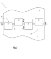
- Figures 1 to 5 show the trim panel 1 to be installed, for example, in a bus or coach.
- the trim panel 1 comprises a first body 2 and a second body 4. These two bodies 2 and 4 are substantially elongated.
- the trim panel 1 comprises a plurality of such bodies secured together such that the panel is also elongated.
- the first body 2 comprises two holding elements 21 and 22 partially located on a abutment edge 24 of the first body 2.
- a first region z 1 known as a fixing region, of the two elements 21 and 22 is fixed to the body 2, by way of example, by adhesive bonding or welding, while a second region z 2 , known as a protruding region, of these bodies extends beyond the abutment edge 24.
- the body 4 comprises two holding elements 41 and 42 partially located on a abutment edge 44.
- a region z 3 known as a fixing region, of the two holding elements 41 and 42 is adhesively bonded or welded to the body 4, with a region z 4 , known as a protruding region, forming a projection extending beyond the abutment edge 44.
- the holding elements 21, 22, 41 and 42 are substantially rectangular pieces made of metal. It should be noted that holding elements having other shapes and made of other types of material can also be provided.
- the two bodies 2 and 4 can be made, by way of example, of thermoplastics when trim panels for the interior of the bus or coach are being produced.
- the trim panel can, to take a non-limiting example, serve as a roof.
- This type of trim can, for example, be joined laterally by screws to a rail on the carcass of the vehicle. Each of the two side edges of the body is thus screwed to each of the rails.
- the panel can also cover a mechanism for opening and closing the doors.
- This door trim can be fixed to the carcass of the vehicle by way of snap fasteners on the lower part and by way of screws on the upper part.
- the panel can be used to cover up an air-conditioning unit. The trim can thus be inserted into a jaw and be fixed to an aluminium sheet by screws.
- the trim panel 1 can also be mounted outside the bus or coach on a side wall. It can then be produced, for example, from sheet metal or aluminium.
- the bodies are substantially planar. They are thus easier to manufacture, for example by moulding, since it is no longer necessary to produce in particular what are known as flanged edges. Moreover, the lack of such edges produces a saving in mass.
- the holding elements 21, 22, 41 and 42 have a guide function such that the two bodies 2 and 4 can be joined together more easily. This is because the two elements 21 and 22 have been fixed to the body 2 leaving a gap substantially greater than the size d 42 of the front of the holding element 42. Thus the element 42 can be introduced and guided between the elements 21 and 22.
- the element 21 can be located between the elements 41 and 42. This is because the gap between these two elements serves as a guide for the element 21 since the size d 21 of the front of the latter is smaller than the distance separating the elements 41 and 42 at the front.
- the protruding distance d defined by the protruding regions z 2 and z 4 is between 10 and 30 mm, preferably between 15 and 20 mm.
- the elements 21 and 22 are in a staggered arrangement with respect to the elements 41 and 42, respectively.
- the two bodies 2 and 4 can thus be fitted together precisely.
- the body 2 is moved in the direction of the arrows F 2 while the body 4 is moved in the direction of the arrows F 4 .
- the body 2 is in contact with the body 4 at their respective abutment edges 24 and 44.
- a lower surface 41 1 of the part of the element 42 extending beyond the body 4 is flush with an upper surface 25 of the body 2.
- the body 2 thus bears against the body 4 by way of the holding elements 21 and 22 while the body 4 bears against the body 2 by way of the holding elements 41 and 42.
- the protruding regions z 2 and z 4 oppose a force f shown in Figure 5 .
- This force f corresponds to the force of gravity when the two bodies 2 and 4 are parallel to the ground.
- the bodies 2 and 4 hold each other in a stable manner. There is no misalignment, in an axis perpendicular to the plane of the panel 1, of the bodies 2 and 4 in the region of contact between their respective abutment edges 24 and 44. Generally, the rigidity of the trim panel 1 is satisfactory.
- the number of bodies can be matched to the desired size of the trim panel, and that the lateral dimension of the bodies can also vary.
- This invention can advantageously be applied to trim panels longer than 7 metres.
- the number of bodies is at least four, and preferably seven.
Landscapes
- Engineering & Computer Science (AREA)
- Mechanical Engineering (AREA)
- Body Structure For Vehicles (AREA)
- Vehicle Interior And Exterior Ornaments, Soundproofing, And Insulation (AREA)
Abstract
- at least one first elongated body (2, 4) having a first and a second abutment edge (24, 44) opposite one another, and
- at least one second elongated body (2, 4) adjacent to the first body and having a third and a fourth abutment edge (24, 44) opposite one another, the third edge being adapted for being located next to the second edge. Furthermore, each of the elongated bodies (2, 4) comprises at least one holding element (21, 22, 41, 42) having a fixing region secured to the body and a region protruding beyond the abutment edge towards the adjacent body, each of the holding elements being adapted for holding the two edges substantially next to one another.
Description
- The present invention relates to a trim panel for a bus or coach and to a bus or coach comprising at least one such panel.
- In the context of panel production, such as an interior roof for a bus or coach, it is known practice to use a series of elongated bodies alongside one another along the entire length of the roof. By way of example, this length can be 12 metres. Each of these bodies comprises what is known as a flanged edge at each of their two abutment sides. In other words, the panel has a substantially flat bottom and at its abutment sides an edge extending upwards by 15 to 20 mm.
- However, there may be lateral play between two adjacent bodies which leads to a poor fit along the entire length of the roof. The overall structure is less rigid as a result and the various bodies of the panel cannot be aligned satisfactorily. This structure is also not very attractive.
- It is an object of the present invention to provide a trim panel for a bus or coach that has no movement, particularly perpendicular to the panel, between each of the adjacent bodies of which it is composed, while ensuring satisfactory structural rigidity.
- To this end, one object of the invention is a trim panel for a bus or coach, comprising:
- at least one first elongated body having a first and a second abutment edge opposite one another, and
- at least one second elongated body adjacent to the first body and having a third and a fourth abutment edge opposite one another, the third edge being adapted for being located next to the second edge,
- By virtue of the trim panel according to the invention, a bus or coach manufacturer has at his disposal a panel, where the bodies which make up said panel are fitted satisfactorily and are produced by a manufacturing method that is easy to implement.
- According to other advantageous features of the trim panel according to the invention, taken individually or in accordance with any technically possible combination:
- the holding elements are fixed to the abutment edges by adhesive bonding or welding;
- each holding element of one elongated body is located between two holding elements of the adjacent elongated body when the two bodies are secured to one another;
- the protruding distance defined by the protruding region is between 10 and 30 mm, preferably between 15 and 20 mm;
- the panel comprises at least four bodies, preferably at least seven bodies, two adjacent bodies being engaged with each other by their respective holding element(s); and
- the holding elements are substantially rectangular and made of metal.
- Another subject of the present invention is a bus or coach comprising at least one trim panel as described hereinabove.
- According to other advantageous features of the coach or bus according to the invention, taken individually or in accordance with any technically possible combination:
- at least one panel forms an interior roof;
- at least one panel conceals an interior mechanical system; and
- at least one panel forms an exterior panel of the bus or coach.
- The invention will be better understood on reading the following description, given purely by way of non-limiting example and referring to the drawings, in which:
-
Figure 1 is a view from above of part of a trim panel according to the present invention, as it is being assembled; -
Figure 2 is a side view of the trim panel part shown inFigure 1 , along arrow II; -
Figure 3 is a view from above of the trim panel part, immediately before assembly; -
Figure 4 is a view from above of the trim panel part, once assembly is complete; and -
Figure 5 is a side view of the trim panel part shown inFigure 4 , along arrow V. -
Figures 1 to 5 show thetrim panel 1 to be installed, for example, in a bus or coach. Thetrim panel 1 comprises afirst body 2 and asecond body 4. These twobodies trim panel 1 comprises a plurality of such bodies secured together such that the panel is also elongated. - The
first body 2 comprises twoholding elements abutment edge 24 of thefirst body 2. A first region z1, known as a fixing region, of the twoelements body 2, by way of example, by adhesive bonding or welding, while a second region z2, known as a protruding region, of these bodies extends beyond theabutment edge 24. - In the same way, the
body 4 comprises twoholding elements abutment edge 44. A region z3, known as a fixing region, of the twoholding elements body 4, with a region z4, known as a protruding region, forming a projection extending beyond theabutment edge 44. - The
holding elements - The two
bodies - The panel can also cover a mechanism for opening and closing the doors. This door trim can be fixed to the carcass of the vehicle by way of snap fasteners on the lower part and by way of screws on the upper part. In addition, the panel can be used to cover up an air-conditioning unit. The trim can thus be inserted into a jaw and be fixed to an aluminium sheet by screws.
- The
trim panel 1 can also be mounted outside the bus or coach on a side wall. It can then be produced, for example, from sheet metal or aluminium. - It can be seen that the bodies are substantially planar. They are thus easier to manufacture, for example by moulding, since it is no longer necessary to produce in particular what are known as flanged edges. Moreover, the lack of such edges produces a saving in mass.
- When the two
bodies respective abutment edges Figures 1 and2 . It can be seen that theholding elements bodies elements body 2 leaving a gap substantially greater than the size d42 of the front of theholding element 42. Thus theelement 42 can be introduced and guided between theelements - In the same way, the
element 21 can be located between theelements element 21 since the size d21 of the front of the latter is smaller than the distance separating theelements - Meanwhile, the protruding distance d defined by the protruding regions z2 and z4 is between 10 and 30 mm, preferably between 15 and 20 mm.
- In other words, the
elements elements bodies - As shown in
Figure 2 , it can be seen that it is advantageous to incline thebodies bodies - The
body 2 is moved in the direction of the arrows F2 while thebody 4 is moved in the direction of the arrows F4. Thus, as shown inFigure 5 , thebody 2 is in contact with thebody 4 at their respective abutment edges 24 and 44. - A
surface 211 of the part of theelement 21 extending beyond thebody 2, this surface being known as the lower surface with respect to the mounted position, if the panel is assumed to correspond to the ceiling, comes into contact with anupper surface 45 of thebody 4. In the same way, alower surface 411 of the part of theelement 42 extending beyond thebody 4 is flush with anupper surface 25 of thebody 2. Thebody 2 thus bears against thebody 4 by way of the holdingelements body 4 bears against thebody 2 by way of the holdingelements Figure 5 . This force f corresponds to the force of gravity when the twobodies - Thus the
bodies panel 1, of thebodies trim panel 1 is satisfactory. - It should be noted that the greater the number of holding elements on either side of the
body trim panel 1. - It is a possibility to position two consecutive holding elements in turn on each of the two bodies. Once the two bodies are secured to one another, two consecutive elements of the first body are thus located between two elements of the adjacent second body.
- In the same way, a number of elements which are not necessarily identical can be provided between each of the two bodies.
- It can also be seen that the number of bodies can be matched to the desired size of the trim panel, and that the lateral dimension of the bodies can also vary.
- In all these configurations, the alignment of this panel is thus ensured.
- This invention can advantageously be applied to trim panels longer than 7 metres. In this case, the number of bodies is at least four, and preferably seven.
Claims (10)
- Trim panel (1) for a bus or coach, comprising:- at least one first elongated body (2, 4) having a first and a second abutment edge (24, 44) opposite one another, and- at least one second elongated body (2, 4) adjacent to the first body and having a third and a fourth abutment edge (24, 44) opposite one another, the third edge being adapted for being located next to the second edge,characterized in that each of the elongated bodies (2, 4) comprises at least one holding element (21, 22, 41, 42) having a fixing region (z1, z3) secured to the body and a region (z2, z4) protruding beyond the abutment edge (24, 44) towards the adjacent body, each of the holding elements being adapted for holding the two edges substantially next to one another.
- Trim panel according to the preceding claim, characterized in that the holding elements (21, 22, 41, 42) are fixed to the abutment edges (24, 44) by adhesive bonding or welding.
- Trim panel according to either of the preceding claims, characterized in that each holding element (21, 22, 41, 42) of one elongated body (2, 4) is located between two holding elements of the adjacent elongated body when the two bodies are secured to one another.
- Trim panel according to any one of the preceding claims, characterized in that the protruding distance (d) defined by the protruding region (z2, z4) is between 10 and 30 mm, preferably between 15 and 20 mm.
- Trim panel according to any one of the preceding claims, characterized in that it comprises at least four bodies, preferably at least seven bodies, two adjacent bodies being engaged with each other by their respective holding element(s).
- Trim panel according to any one of the preceding claims, characterized in that the holding elements (21, 22, 41, 42) are substantially rectangular and made of metal.
- Bus or coach comprising at least one trim panel (1) according to any one of the preceding claims.
- Bus or coach according to Claim 7, characterized in that at least one panel forms an interior roof.
- Bus or coach according to Claim 7 or 8, characterized in that at least one panel conceals an interior mechanical system.
- Bus or coach according to Claim 7, 8 or 9, characterized in that at least one panel forms an exterior panel of the bus or coach.
Priority Applications (2)
| Application Number | Priority Date | Filing Date | Title |
|---|---|---|---|
| EP20080170245 EP2192005B1 (en) | 2008-11-28 | 2008-11-28 | Trim panel for a bus or coach and bus or coach comprising at least one such panel |
| ES08170245T ES2424391T3 (en) | 2008-11-28 | 2008-11-28 | Decorative panel for a bus or coach, and bus or coach comprising at least one such panel |
Applications Claiming Priority (1)
| Application Number | Priority Date | Filing Date | Title |
|---|---|---|---|
| EP20080170245 EP2192005B1 (en) | 2008-11-28 | 2008-11-28 | Trim panel for a bus or coach and bus or coach comprising at least one such panel |
Publications (2)
| Publication Number | Publication Date |
|---|---|
| EP2192005A1 true EP2192005A1 (en) | 2010-06-02 |
| EP2192005B1 EP2192005B1 (en) | 2013-05-22 |
Family
ID=40552293
Family Applications (1)
| Application Number | Title | Priority Date | Filing Date |
|---|---|---|---|
| EP20080170245 Active EP2192005B1 (en) | 2008-11-28 | 2008-11-28 | Trim panel for a bus or coach and bus or coach comprising at least one such panel |
Country Status (2)
| Country | Link |
|---|---|
| EP (1) | EP2192005B1 (en) |
| ES (1) | ES2424391T3 (en) |
Citations (5)
| Publication number | Priority date | Publication date | Assignee | Title |
|---|---|---|---|---|
| DE3644496A1 (en) * | 1986-12-24 | 1988-07-07 | Iveco Magirus | Vehicle supporting structure |
| WO2002058965A1 (en) * | 2001-01-23 | 2002-08-01 | Silcraft Pty Ltd | A two part trim for a surface and a method of providing a two part trim for application to a surface |
| US20040239151A1 (en) * | 2001-09-21 | 2004-12-02 | Alexander Czinki | Paneling element for the roof of a vehicle interior |
| US20060102786A1 (en) * | 2004-10-13 | 2006-05-18 | Airbus Deutschland Gmbh | Joint cover in aircraft |
| DE102006037854A1 (en) | 2006-08-11 | 2008-03-20 | Johnson Controls Interiors Gmbh & Co. Kg | Inner lining part for vehicle, has two inner lining panels, which are provided with integral conducting paths, and mechanical connection between both inner lining panels are realized by contact element between two panels |
-
2008
- 2008-11-28 ES ES08170245T patent/ES2424391T3/en active Active
- 2008-11-28 EP EP20080170245 patent/EP2192005B1/en active Active
Patent Citations (5)
| Publication number | Priority date | Publication date | Assignee | Title |
|---|---|---|---|---|
| DE3644496A1 (en) * | 1986-12-24 | 1988-07-07 | Iveco Magirus | Vehicle supporting structure |
| WO2002058965A1 (en) * | 2001-01-23 | 2002-08-01 | Silcraft Pty Ltd | A two part trim for a surface and a method of providing a two part trim for application to a surface |
| US20040239151A1 (en) * | 2001-09-21 | 2004-12-02 | Alexander Czinki | Paneling element for the roof of a vehicle interior |
| US20060102786A1 (en) * | 2004-10-13 | 2006-05-18 | Airbus Deutschland Gmbh | Joint cover in aircraft |
| DE102006037854A1 (en) | 2006-08-11 | 2008-03-20 | Johnson Controls Interiors Gmbh & Co. Kg | Inner lining part for vehicle, has two inner lining panels, which are provided with integral conducting paths, and mechanical connection between both inner lining panels are realized by contact element between two panels |
Also Published As
| Publication number | Publication date |
|---|---|
| ES2424391T3 (en) | 2013-10-01 |
| EP2192005B1 (en) | 2013-05-22 |
Similar Documents
| Publication | Publication Date | Title |
|---|---|---|
| US7316448B2 (en) | Cowl top cover | |
| EP3034342B1 (en) | Vehicle back door joining method | |
| CN105246723A (en) | Window panel support structure | |
| JP5802160B2 (en) | Railway vehicle equipped with cab and cab | |
| CN108146364A (en) | Body construction and decorative element | |
| CN110461634B (en) | Glass device for a vehicle door, motor vehicle, method for producing a vehicle door, and sealing device | |
| US9783240B2 (en) | Lateral upright for motor vehicle body shell | |
| JP6034974B2 (en) | Railway car body | |
| US11794564B2 (en) | Body structure for an electrically operated vehicle | |
| US20150259971A1 (en) | Door of platform door apparatus | |
| US10118651B2 (en) | Interior body panel fit and finish tabs and methods of installation and use thereof | |
| EP2192005B1 (en) | Trim panel for a bus or coach and bus or coach comprising at least one such panel | |
| JP5662226B2 (en) | Sliding door pocket and construction method of sliding door pocket | |
| EP1702779B1 (en) | Automotive vehicle door with a window | |
| JP2015067429A (en) | Elevator panel | |
| KR101394374B1 (en) | Transparent soundproof plate and maintenance method thereof | |
| JP2010173495A (en) | Vehicle-mounted packing box of adhesive structure, and assembling method therefor | |
| JP2009173078A (en) | Vehicle door | |
| JP6238885B2 (en) | Railcar interior panel structure | |
| RU203822U1 (en) | Vehicle body connector | |
| RU91319U1 (en) | INTERIOR WALL PANEL WAGON (OPTIONS) | |
| CN204676443U (en) | Novel off-load formula acoustic barrier unit board | |
| CN108556598B (en) | sunshade curtain installation mechanism | |
| JP2014144701A (en) | Door structure for railway vehicle | |
| CN212292453U (en) | Elevator door pocket |
Legal Events
| Date | Code | Title | Description |
|---|---|---|---|
| PUAI | Public reference made under article 153(3) epc to a published international application that has entered the european phase |
Free format text: ORIGINAL CODE: 0009012 |
|
| AK | Designated contracting states |
Kind code of ref document: A1 Designated state(s): AT BE BG CH CY CZ DE DK EE ES FI FR GB GR HR HU IE IS IT LI LT LU LV MC MT NL NO PL PT RO SE SI SK TR |
|
| AX | Request for extension of the european patent |
Extension state: AL BA MK RS |
|
| 17P | Request for examination filed |
Effective date: 20100527 |
|
| AKX | Designation fees paid |
Designated state(s): AT BE BG CH CY CZ DE DK EE ES FI FR GB GR HR HU IE IS IT LI LT LU LV MC MT NL NO PL PT RO SE SI SK TR |
|
| GRAP | Despatch of communication of intention to grant a patent |
Free format text: ORIGINAL CODE: EPIDOSNIGR1 |
|
| GRAS | Grant fee paid |
Free format text: ORIGINAL CODE: EPIDOSNIGR3 |
|
| GRAA | (expected) grant |
Free format text: ORIGINAL CODE: 0009210 |
|
| AK | Designated contracting states |
Kind code of ref document: B1 Designated state(s): AT BE BG CH CY CZ DE DK EE ES FI FR GB GR HR HU IE IS IT LI LT LU LV MC MT NL NO PL PT RO SE SI SK TR |
|
| REG | Reference to a national code |
Ref country code: GB Ref legal event code: FG4D |
|
| REG | Reference to a national code |
Ref country code: CH Ref legal event code: EP |
|
| REG | Reference to a national code |
Ref country code: AT Ref legal event code: REF Ref document number: 613037 Country of ref document: AT Kind code of ref document: T Effective date: 20130615 |
|
| REG | Reference to a national code |
Ref country code: IE Ref legal event code: FG4D |
|
| REG | Reference to a national code |
Ref country code: DE Ref legal event code: R096 Ref document number: 602008024725 Country of ref document: DE Effective date: 20130718 |
|
| REG | Reference to a national code |
Ref country code: SE Ref legal event code: TRGR |
|
| REG | Reference to a national code |
Ref country code: ES Ref legal event code: FG2A Ref document number: 2424391 Country of ref document: ES Kind code of ref document: T3 Effective date: 20131001 |
|
| REG | Reference to a national code |
Ref country code: NL Ref legal event code: T3 |
|
| REG | Reference to a national code |
Ref country code: AT Ref legal event code: MK05 Ref document number: 613037 Country of ref document: AT Kind code of ref document: T Effective date: 20130522 |
|
| REG | Reference to a national code |
Ref country code: LT Ref legal event code: MG4D |
|
| PG25 | Lapsed in a contracting state [announced via postgrant information from national office to epo] |
Ref country code: PT Free format text: LAPSE BECAUSE OF FAILURE TO SUBMIT A TRANSLATION OF THE DESCRIPTION OR TO PAY THE FEE WITHIN THE PRESCRIBED TIME-LIMIT Effective date: 20130923 Ref country code: SI Free format text: LAPSE BECAUSE OF FAILURE TO SUBMIT A TRANSLATION OF THE DESCRIPTION OR TO PAY THE FEE WITHIN THE PRESCRIBED TIME-LIMIT Effective date: 20130522 Ref country code: GR Free format text: LAPSE BECAUSE OF FAILURE TO SUBMIT A TRANSLATION OF THE DESCRIPTION OR TO PAY THE FEE WITHIN THE PRESCRIBED TIME-LIMIT Effective date: 20130823 Ref country code: IS Free format text: LAPSE BECAUSE OF FAILURE TO SUBMIT A TRANSLATION OF THE DESCRIPTION OR TO PAY THE FEE WITHIN THE PRESCRIBED TIME-LIMIT Effective date: 20130922 Ref country code: FI Free format text: LAPSE BECAUSE OF FAILURE TO SUBMIT A TRANSLATION OF THE DESCRIPTION OR TO PAY THE FEE WITHIN THE PRESCRIBED TIME-LIMIT Effective date: 20130522 Ref country code: LT Free format text: LAPSE BECAUSE OF FAILURE TO SUBMIT A TRANSLATION OF THE DESCRIPTION OR TO PAY THE FEE WITHIN THE PRESCRIBED TIME-LIMIT Effective date: 20130522 Ref country code: AT Free format text: LAPSE BECAUSE OF FAILURE TO SUBMIT A TRANSLATION OF THE DESCRIPTION OR TO PAY THE FEE WITHIN THE PRESCRIBED TIME-LIMIT Effective date: 20130522 Ref country code: NO Free format text: LAPSE BECAUSE OF FAILURE TO SUBMIT A TRANSLATION OF THE DESCRIPTION OR TO PAY THE FEE WITHIN THE PRESCRIBED TIME-LIMIT Effective date: 20130822 |
|
| PG25 | Lapsed in a contracting state [announced via postgrant information from national office to epo] |
Ref country code: BG Free format text: LAPSE BECAUSE OF FAILURE TO SUBMIT A TRANSLATION OF THE DESCRIPTION OR TO PAY THE FEE WITHIN THE PRESCRIBED TIME-LIMIT Effective date: 20130822 Ref country code: PL Free format text: LAPSE BECAUSE OF FAILURE TO SUBMIT A TRANSLATION OF THE DESCRIPTION OR TO PAY THE FEE WITHIN THE PRESCRIBED TIME-LIMIT Effective date: 20130522 Ref country code: HR Free format text: LAPSE BECAUSE OF FAILURE TO SUBMIT A TRANSLATION OF THE DESCRIPTION OR TO PAY THE FEE WITHIN THE PRESCRIBED TIME-LIMIT Effective date: 20130522 |
|
| PG25 | Lapsed in a contracting state [announced via postgrant information from national office to epo] |
Ref country code: LV Free format text: LAPSE BECAUSE OF FAILURE TO SUBMIT A TRANSLATION OF THE DESCRIPTION OR TO PAY THE FEE WITHIN THE PRESCRIBED TIME-LIMIT Effective date: 20130522 |
|
| PG25 | Lapsed in a contracting state [announced via postgrant information from national office to epo] |
Ref country code: CZ Free format text: LAPSE BECAUSE OF FAILURE TO SUBMIT A TRANSLATION OF THE DESCRIPTION OR TO PAY THE FEE WITHIN THE PRESCRIBED TIME-LIMIT Effective date: 20130522 Ref country code: DK Free format text: LAPSE BECAUSE OF FAILURE TO SUBMIT A TRANSLATION OF THE DESCRIPTION OR TO PAY THE FEE WITHIN THE PRESCRIBED TIME-LIMIT Effective date: 20130522 Ref country code: EE Free format text: LAPSE BECAUSE OF FAILURE TO SUBMIT A TRANSLATION OF THE DESCRIPTION OR TO PAY THE FEE WITHIN THE PRESCRIBED TIME-LIMIT Effective date: 20130522 Ref country code: SK Free format text: LAPSE BECAUSE OF FAILURE TO SUBMIT A TRANSLATION OF THE DESCRIPTION OR TO PAY THE FEE WITHIN THE PRESCRIBED TIME-LIMIT Effective date: 20130522 Ref country code: BE Free format text: LAPSE BECAUSE OF FAILURE TO SUBMIT A TRANSLATION OF THE DESCRIPTION OR TO PAY THE FEE WITHIN THE PRESCRIBED TIME-LIMIT Effective date: 20130522 |
|
| PG25 | Lapsed in a contracting state [announced via postgrant information from national office to epo] |
Ref country code: RO Free format text: LAPSE BECAUSE OF FAILURE TO SUBMIT A TRANSLATION OF THE DESCRIPTION OR TO PAY THE FEE WITHIN THE PRESCRIBED TIME-LIMIT Effective date: 20130522 |
|
| PLBE | No opposition filed within time limit |
Free format text: ORIGINAL CODE: 0009261 |
|
| 26N | No opposition filed |
Effective date: 20140225 |
|
| REG | Reference to a national code |
Ref country code: DE Ref legal event code: R097 Ref document number: 602008024725 Country of ref document: DE Effective date: 20140225 |
|
| REG | Reference to a national code |
Ref country code: CH Ref legal event code: PL |
|
| PG25 | Lapsed in a contracting state [announced via postgrant information from national office to epo] |
Ref country code: LI Free format text: LAPSE BECAUSE OF NON-PAYMENT OF DUE FEES Effective date: 20131130 Ref country code: CH Free format text: LAPSE BECAUSE OF NON-PAYMENT OF DUE FEES Effective date: 20131130 Ref country code: MC Free format text: LAPSE BECAUSE OF FAILURE TO SUBMIT A TRANSLATION OF THE DESCRIPTION OR TO PAY THE FEE WITHIN THE PRESCRIBED TIME-LIMIT Effective date: 20130522 |
|
| REG | Reference to a national code |
Ref country code: IE Ref legal event code: MM4A |
|
| PG25 | Lapsed in a contracting state [announced via postgrant information from national office to epo] |
Ref country code: IE Free format text: LAPSE BECAUSE OF NON-PAYMENT OF DUE FEES Effective date: 20131128 |
|
| PG25 | Lapsed in a contracting state [announced via postgrant information from national office to epo] |
Ref country code: TR Free format text: LAPSE BECAUSE OF FAILURE TO SUBMIT A TRANSLATION OF THE DESCRIPTION OR TO PAY THE FEE WITHIN THE PRESCRIBED TIME-LIMIT Effective date: 20130522 Ref country code: CY Free format text: LAPSE BECAUSE OF FAILURE TO SUBMIT A TRANSLATION OF THE DESCRIPTION OR TO PAY THE FEE WITHIN THE PRESCRIBED TIME-LIMIT Effective date: 20130522 |
|
| PG25 | Lapsed in a contracting state [announced via postgrant information from national office to epo] |
Ref country code: LU Free format text: LAPSE BECAUSE OF NON-PAYMENT OF DUE FEES Effective date: 20131128 Ref country code: HU Free format text: LAPSE BECAUSE OF FAILURE TO SUBMIT A TRANSLATION OF THE DESCRIPTION OR TO PAY THE FEE WITHIN THE PRESCRIBED TIME-LIMIT; INVALID AB INITIO Effective date: 20081128 |
|
| PG25 | Lapsed in a contracting state [announced via postgrant information from national office to epo] |
Ref country code: MT Free format text: LAPSE BECAUSE OF FAILURE TO SUBMIT A TRANSLATION OF THE DESCRIPTION OR TO PAY THE FEE WITHIN THE PRESCRIBED TIME-LIMIT Effective date: 20130522 |
|
| REG | Reference to a national code |
Ref country code: FR Ref legal event code: PLFP Year of fee payment: 8 |
|
| REG | Reference to a national code |
Ref country code: DE Ref legal event code: R082 Ref document number: 602008024725 Country of ref document: DE Representative=s name: SCHWABE SANDMAIR MARX PATENTANWAELTE RECHTSANW, DE Ref country code: DE Ref legal event code: R082 Ref document number: 602008024725 Country of ref document: DE Representative=s name: SSM SANDMAIR PATENTANWAELTE RECHTSANWALT PARTN, DE |
|
| REG | Reference to a national code |
Ref country code: FR Ref legal event code: PLFP Year of fee payment: 9 |
|
| REG | Reference to a national code |
Ref country code: FR Ref legal event code: PLFP Year of fee payment: 10 |
|
| PGFP | Annual fee paid to national office [announced via postgrant information from national office to epo] |
Ref country code: SE Payment date: 20221123 Year of fee payment: 15 Ref country code: NL Payment date: 20221124 Year of fee payment: 15 |
|
| REG | Reference to a national code |
Ref country code: NL Ref legal event code: PD Owner name: IVECO FRANCE S.A.S.; FR Free format text: DETAILS ASSIGNMENT: CHANGE OF OWNER(S), CHANGE OF LEGAL ENTITY; FORMER OWNER NAME: IVECO FRANCE S.A. Effective date: 20230406 |
|
| REG | Reference to a national code |
Ref country code: DE Ref legal event code: R081 Ref document number: 602008024725 Country of ref document: DE Owner name: IVECO FRANCE S.A.S., FR Free format text: FORMER OWNER: IVECO FRANCE S.A., VENISSIEUX, FR |
|
| P01 | Opt-out of the competence of the unified patent court (upc) registered |
Effective date: 20230522 |
|
| REG | Reference to a national code |
Ref country code: ES Ref legal event code: PC2A Owner name: IVECO FRANCE S.A.S. Effective date: 20240614 |
|
| REG | Reference to a national code |
Ref country code: SE Ref legal event code: EUG |
|
| REG | Reference to a national code |
Ref country code: NL Ref legal event code: MM Effective date: 20231201 |
|
| PG25 | Lapsed in a contracting state [announced via postgrant information from national office to epo] |
Ref country code: SE Free format text: LAPSE BECAUSE OF NON-PAYMENT OF DUE FEES Effective date: 20231129 |
|
| PG25 | Lapsed in a contracting state [announced via postgrant information from national office to epo] |
Ref country code: NL Free format text: LAPSE BECAUSE OF NON-PAYMENT OF DUE FEES Effective date: 20231201 |
|
| PG25 | Lapsed in a contracting state [announced via postgrant information from national office to epo] |
Ref country code: NL Free format text: LAPSE BECAUSE OF NON-PAYMENT OF DUE FEES Effective date: 20231201 |
|
| PGFP | Annual fee paid to national office [announced via postgrant information from national office to epo] |
Ref country code: DE Payment date: 20241128 Year of fee payment: 17 |
|
| PGFP | Annual fee paid to national office [announced via postgrant information from national office to epo] |
Ref country code: GB Payment date: 20241126 Year of fee payment: 17 |
|
| PGFP | Annual fee paid to national office [announced via postgrant information from national office to epo] |
Ref country code: FR Payment date: 20241126 Year of fee payment: 17 |
|
| PGFP | Annual fee paid to national office [announced via postgrant information from national office to epo] |
Ref country code: IT Payment date: 20241111 Year of fee payment: 17 Ref country code: ES Payment date: 20241218 Year of fee payment: 17 |