EP2191953A1 - Oven for the thermal conditioning of preforms, comprising a ventilation plenum - Google Patents
Oven for the thermal conditioning of preforms, comprising a ventilation plenum Download PDFInfo
- Publication number
- EP2191953A1 EP2191953A1 EP09176755A EP09176755A EP2191953A1 EP 2191953 A1 EP2191953 A1 EP 2191953A1 EP 09176755 A EP09176755 A EP 09176755A EP 09176755 A EP09176755 A EP 09176755A EP 2191953 A1 EP2191953 A1 EP 2191953A1
- Authority
- EP
- European Patent Office
- Prior art keywords
- air
- oven
- filter
- zone
- preforms
- Prior art date
- Legal status (The legal status is an assumption and is not a legal conclusion. Google has not performed a legal analysis and makes no representation as to the accuracy of the status listed.)
- Granted
Links
- 238000009423 ventilation Methods 0.000 title claims abstract description 77
- 230000003750 conditioning effect Effects 0.000 title claims description 9
- 238000010438 heat treatment Methods 0.000 claims abstract description 62
- 238000000605 extraction Methods 0.000 claims abstract description 59
- 238000001816 cooling Methods 0.000 claims abstract description 32
- 238000011144 upstream manufacturing Methods 0.000 claims abstract description 32
- 238000001914 filtration Methods 0.000 claims description 31
- 238000011045 prefiltration Methods 0.000 claims description 22
- 239000002245 particle Substances 0.000 claims description 9
- 238000001514 detection method Methods 0.000 claims description 4
- 239000012815 thermoplastic material Substances 0.000 claims description 3
- 238000004519 manufacturing process Methods 0.000 description 13
- 210000003739 neck Anatomy 0.000 description 10
- 230000005855 radiation Effects 0.000 description 9
- 230000002093 peripheral effect Effects 0.000 description 7
- 230000003749 cleanliness Effects 0.000 description 6
- MHAJPDPJQMAIIY-UHFFFAOYSA-N Hydrogen peroxide Chemical compound OO MHAJPDPJQMAIIY-UHFFFAOYSA-N 0.000 description 5
- 238000000071 blow moulding Methods 0.000 description 5
- 238000007664 blowing Methods 0.000 description 5
- 230000004907 flux Effects 0.000 description 5
- 238000005259 measurement Methods 0.000 description 5
- 230000000694 effects Effects 0.000 description 4
- 229920000139 polyethylene terephthalate Polymers 0.000 description 4
- 239000005020 polyethylene terephthalate Substances 0.000 description 4
- 238000012423 maintenance Methods 0.000 description 3
- 239000003206 sterilizing agent Substances 0.000 description 3
- 238000003756 stirring Methods 0.000 description 3
- 239000003795 chemical substances by application Substances 0.000 description 2
- 230000000295 complement effect Effects 0.000 description 2
- 238000009833 condensation Methods 0.000 description 2
- 230000005494 condensation Effects 0.000 description 2
- 238000005202 decontamination Methods 0.000 description 2
- 230000003588 decontaminative effect Effects 0.000 description 2
- 230000003247 decreasing effect Effects 0.000 description 2
- 230000008021 deposition Effects 0.000 description 2
- 230000003071 parasitic effect Effects 0.000 description 2
- -1 polyethylene terephthalate Polymers 0.000 description 2
- 229920001169 thermoplastic Polymers 0.000 description 2
- 239000004416 thermosoftening plastic Substances 0.000 description 2
- 230000009466 transformation Effects 0.000 description 2
- 238000012550 audit Methods 0.000 description 1
- 230000015556 catabolic process Effects 0.000 description 1
- 238000005253 cladding Methods 0.000 description 1
- 239000011362 coarse particle Substances 0.000 description 1
- 230000001143 conditioned effect Effects 0.000 description 1
- 238000010276 construction Methods 0.000 description 1
- 238000006731 degradation reaction Methods 0.000 description 1
- 230000000593 degrading effect Effects 0.000 description 1
- 230000002542 deteriorative effect Effects 0.000 description 1
- 230000001627 detrimental effect Effects 0.000 description 1
- 239000010419 fine particle Substances 0.000 description 1
- 230000009477 glass transition Effects 0.000 description 1
- 230000005484 gravity Effects 0.000 description 1
- 238000002347 injection Methods 0.000 description 1
- 239000007924 injection Substances 0.000 description 1
- 238000007689 inspection Methods 0.000 description 1
- 230000001678 irradiating effect Effects 0.000 description 1
- 238000000465 moulding Methods 0.000 description 1
- 230000000149 penetrating effect Effects 0.000 description 1
- 230000035515 penetration Effects 0.000 description 1
- 230000001737 promoting effect Effects 0.000 description 1
- 238000011012 sanitization Methods 0.000 description 1
- 230000006641 stabilisation Effects 0.000 description 1
- 238000011105 stabilization Methods 0.000 description 1
- 230000001954 sterilising effect Effects 0.000 description 1
- 238000004659 sterilization and disinfection Methods 0.000 description 1
- 231100000331 toxic Toxicity 0.000 description 1
- 230000002588 toxic effect Effects 0.000 description 1
- 210000001835 viscera Anatomy 0.000 description 1
- XLYOFNOQVPJJNP-UHFFFAOYSA-N water Substances O XLYOFNOQVPJJNP-UHFFFAOYSA-N 0.000 description 1
Images


Classifications
-
- B—PERFORMING OPERATIONS; TRANSPORTING
- B29—WORKING OF PLASTICS; WORKING OF SUBSTANCES IN A PLASTIC STATE IN GENERAL
- B29C—SHAPING OR JOINING OF PLASTICS; SHAPING OF MATERIAL IN A PLASTIC STATE, NOT OTHERWISE PROVIDED FOR; AFTER-TREATMENT OF THE SHAPED PRODUCTS, e.g. REPAIRING
- B29C49/00—Blow-moulding, i.e. blowing a preform or parison to a desired shape within a mould; Apparatus therefor
- B29C49/42—Component parts, details or accessories; Auxiliary operations
- B29C49/64—Heating or cooling preforms, parisons or blown articles
- B29C49/68—Ovens specially adapted for heating preforms or parisons
-
- B—PERFORMING OPERATIONS; TRANSPORTING
- B29—WORKING OF PLASTICS; WORKING OF SUBSTANCES IN A PLASTIC STATE IN GENERAL
- B29C—SHAPING OR JOINING OF PLASTICS; SHAPING OF MATERIAL IN A PLASTIC STATE, NOT OTHERWISE PROVIDED FOR; AFTER-TREATMENT OF THE SHAPED PRODUCTS, e.g. REPAIRING
- B29C49/00—Blow-moulding, i.e. blowing a preform or parison to a desired shape within a mould; Apparatus therefor
- B29C49/42—Component parts, details or accessories; Auxiliary operations
- B29C49/46—Component parts, details or accessories; Auxiliary operations characterised by using particular environment or blow fluids other than air
- B29C2049/4602—Blowing fluids
- B29C2049/4632—Blowing fluids being filtered air
-
- B—PERFORMING OPERATIONS; TRANSPORTING
- B29—WORKING OF PLASTICS; WORKING OF SUBSTANCES IN A PLASTIC STATE IN GENERAL
- B29C—SHAPING OR JOINING OF PLASTICS; SHAPING OF MATERIAL IN A PLASTIC STATE, NOT OTHERWISE PROVIDED FOR; AFTER-TREATMENT OF THE SHAPED PRODUCTS, e.g. REPAIRING
- B29C2949/00—Indexing scheme relating to blow-moulding
- B29C2949/07—Preforms or parisons characterised by their configuration
- B29C2949/0715—Preforms or parisons characterised by their configuration the preform having one end closed
-
- B—PERFORMING OPERATIONS; TRANSPORTING
- B29—WORKING OF PLASTICS; WORKING OF SUBSTANCES IN A PLASTIC STATE IN GENERAL
- B29C—SHAPING OR JOINING OF PLASTICS; SHAPING OF MATERIAL IN A PLASTIC STATE, NOT OTHERWISE PROVIDED FOR; AFTER-TREATMENT OF THE SHAPED PRODUCTS, e.g. REPAIRING
- B29C49/00—Blow-moulding, i.e. blowing a preform or parison to a desired shape within a mould; Apparatus therefor
- B29C49/02—Combined blow-moulding and manufacture of the preform or the parison
- B29C49/06—Injection blow-moulding
-
- B—PERFORMING OPERATIONS; TRANSPORTING
- B29—WORKING OF PLASTICS; WORKING OF SUBSTANCES IN A PLASTIC STATE IN GENERAL
- B29C—SHAPING OR JOINING OF PLASTICS; SHAPING OF MATERIAL IN A PLASTIC STATE, NOT OTHERWISE PROVIDED FOR; AFTER-TREATMENT OF THE SHAPED PRODUCTS, e.g. REPAIRING
- B29C49/00—Blow-moulding, i.e. blowing a preform or parison to a desired shape within a mould; Apparatus therefor
- B29C49/42—Component parts, details or accessories; Auxiliary operations
- B29C49/42414—Treatment of preforms, e.g. cleaning or spraying water for improved heat transfer
- B29C49/42416—Purging or cleaning the preforms
- B29C49/42418—Purging or cleaning the preforms for sterilizing
-
- B—PERFORMING OPERATIONS; TRANSPORTING
- B29—WORKING OF PLASTICS; WORKING OF SUBSTANCES IN A PLASTIC STATE IN GENERAL
- B29C—SHAPING OR JOINING OF PLASTICS; SHAPING OF MATERIAL IN A PLASTIC STATE, NOT OTHERWISE PROVIDED FOR; AFTER-TREATMENT OF THE SHAPED PRODUCTS, e.g. REPAIRING
- B29C49/00—Blow-moulding, i.e. blowing a preform or parison to a desired shape within a mould; Apparatus therefor
- B29C49/42—Component parts, details or accessories; Auxiliary operations
- B29C49/64—Heating or cooling preforms, parisons or blown articles
- B29C49/68—Ovens specially adapted for heating preforms or parisons
- B29C49/6845—Ovens specially adapted for heating preforms or parisons using ventilation, e.g. a fan
-
- B—PERFORMING OPERATIONS; TRANSPORTING
- B29—WORKING OF PLASTICS; WORKING OF SUBSTANCES IN A PLASTIC STATE IN GENERAL
- B29C—SHAPING OR JOINING OF PLASTICS; SHAPING OF MATERIAL IN A PLASTIC STATE, NOT OTHERWISE PROVIDED FOR; AFTER-TREATMENT OF THE SHAPED PRODUCTS, e.g. REPAIRING
- B29C49/00—Blow-moulding, i.e. blowing a preform or parison to a desired shape within a mould; Apparatus therefor
- B29C49/42—Component parts, details or accessories; Auxiliary operations
- B29C49/64—Heating or cooling preforms, parisons or blown articles
- B29C49/68—Ovens specially adapted for heating preforms or parisons
- B29C49/6855—Cooling of heating means, e.g. avoiding overheating
Definitions
- the invention relates to an oven for the thermal conditioning of thermoplastic container preforms which comprises a ventilation plenum.
- thermoplastic material for example PET (polyethylene terephthalate)
- PET polyethylene terephthalate
- Such preforms are preconditioned thermally in an oven to allow their transformation, in particular by a blowing operation, or stretch-blow molding, in a container.
- the preforms generally have a specimen shape mainly comprising a body, more or less long, and a neck that already has its final shape.
- the neck of the preform forms the neck of the container and comprises for example a thread for receiving a screw cap.
- Such an oven comprises mainly and successively from upstream to downstream according to the direction of flow of the cooling air flow, an air intake zone, a preform heating zone and a downstream extraction zone. air.
- the zones are for example integrated inside the furnace and are arranged so that the extraction in the extraction zone is carried out at the upper or upper part of the furnace, the heating zone being interposed between the admission zone and the extraction zone.
- the heating zone is equipped with means for heating the preforms, for example infrared radiation lamps.
- the heating means are aligned in the oven so as to extend along all or part of the path of the preforms in the oven.
- the oven comprises a plurality of ventilation modules which are arranged in the furnace heating zone and which are aligned with respect to the heating means, in order to mix the air in the vicinity of the preforms.
- the function of the ventilation modules is to moderate the effects of thermal conduction through the air mass contained in the oven and to make maximum use of the infrared radiation of the heating means, in order to warm up the thickness of the body as much as possible. preforms without burning the skin. This makes it possible to prevent any degradation of the skin of the preforms, but also to keep the environment of the heating zone below temperatures likely to affect the mechanical parts therein, such as, for example, the caps of the radiation lamps. infrared.
- Each ventilation module is connected to a tubular air intake duct of circular section which extends into the intake zone of the oven and which opens out of the oven.
- each fan module has a rotatably mounted centrifugal impeller that draws air through the intake duct and blows the air thus sucked into the preforms, so that the flow of cooling air flows. in the vicinity of the preforms to stir the hot air within the furnace heating zone.
- Each centrifugal wheel is arranged in a housing which guides the flow of cooling air to the preforms.
- infrared radiation is best exploited, which enables the body of the preforms to be raised to the desired temperature. homogeneous way on the thickness of the wall of the body, without deteriorating the skin of the body of the preforms or soften the neck of the preforms.
- the furnace comprises means of protection which are able to protect the necks of the preforms from infrared radiation, as well as means dedicated to the cooling of the necks, which are for example constituted by a part of the flow of cooling air and / or additional cooling means, in particular by circulation of water.
- the furnace air extraction zone comprises extracting means which are associated with the extraction duct, such as an extractor hood.
- the hood overhangs the heating zone, and is intended to extract the air coming from the heating zone of the oven to the outside through the extraction duct, in particular in order to evacuate calories from the oven.
- Such extraction means also make it possible to recover and evacuate toxic residual vapors of sterilizing agent when a decontamination operation of the interior of the preforms is carried out simultaneously with the thermal conditioning.
- Such a decontamination operation is advantageously obtained by the deposition by condensation of a sterilizing agent - such as hydrogen peroxide (H2O2) - intended to be activated thermally in the oven by the heating means and then discharged in the vapor state. by the air extraction means.
- a sterilizing agent - such as hydrogen peroxide (H2O2) - intended to be activated thermally in the oven by the heating means and then discharged in the vapor state. by the air extraction means.
- Another concern of those skilled in the art generally relates to the hygiene and cleanliness of the containers, thus the cleanliness of the preforms intended to be transformed into containers after heating by blow molding (or stretch-blow molding), the containers being then preferably filled directly into an aseptic medium after their manufacture.
- each intake duct it is known to equip the free end of each intake duct by an inlet mouth in which air filtering means are arranged, so that the ventilation modules deliver to the preforms a filtered air. having a certain degree of cleanliness.
- the quality of the ventilated air depends on the efficiency of the filters.
- a pressure drop is detrimental to the proper functioning of the furnace since it results in a decrease in the flow of air blown to the preforms by the ventilation modules and therefore in a drop in air cooling performance in the vicinity of the preforms .
- the invention aims in particular to further improve the cleanliness of the preforms, and therefore the containers, without however altering the thermal conditioning of the preforms operated in the furnace, nor the flow of ventilated air on the preforms by the ventilation modules.
- the invention proposes in particular to promote the filtration quality of the filtration means, while limiting the pressure losses in the air intake circuit, or cooling.
- the air distribution chamber it increases the ratio of the filtration quality of the air sucked in relation to the pressure drop.
- such a distribution chamber defines a large common volume of filtered air in which each ventilation module draws filtered air, whereby the pressure losses are reduced.
- such a distribution chamber thanks to its volume and its compactness, makes it possible to limit the restrictions in the cooling circuit, which oppose the flow of the cooling air flow and favor the pressure losses. .
- upstream and downstream will also be used with reference to the flow direction of the cooling air flow inside the oven, that is to say from the so-called upstream admission zone the extraction zone, called downstream, of the furnace.
- thermoplastic material for example PET (polyethylene terephthalate).
- the furnace 10 comprises for example here a heating path of the "U" preforms comprising two parallel longitudinal heating sections, one go, the other return, connected together a transverse curvilinear section, said stabilization.
- the furnace 10 is generally in the form of a tunnel extending longitudinally, from back to front, from a first rear side 12, to a closed second front side 14.
- the rear side 12 is open to allow the passage of the preforms. However, it is open in an overpressure zone, as will be described later, so that polluting particles can not enter the furnace by this rear side 12.
- the furnace 10 has a general design symmetry with respect to a median vertical plane (not shown) extending longitudinally through the middle of the furnace 10, and identical elements are designated by the same indexed references.
- the oven 10 is only one of the stations of a container manufacturing facility, for example bottles, from preforms.
- Such a manufacturing facility comprises for example a feeding device (not shown) in preforms, which feeds the furnace 10 in preforms by the rear side 12 of the furnace 10.
- the preforms are introduced inside the furnace 10 by transfer means at the rear side 12 where the preforms are supported by conveying means of the furnace 10, an operation also called "cladding".
- the preforms are then entrained in the furnace 10 by the conveying means (not shown), for example here following a U-shaped heating path.
- the preforms emerge from the furnace 10 through the rear side 12 and are, after having been thermally conditioned by the furnace 10, taken over by other transfer means (not shown) to direct them directly to a molding device. (not shown) for blow-molding or stretch-blow molding into a container.
- the conveying means of the preforms are capable of transporting the preforms along the heating path and comprise support elements (not shown), also sometimes called “spinners", each of which cooperates with the inner wall of the neck of each preform.
- the support elements of the conveying means are able to rotate each of the preforms in rotation in order to promote an appropriate distribution of heat in the body of each preform.
- the furnace 10 is traversed by a flow of air A preform cooling, which flows from upstream to downstream, through the furnace 10, more precisely here vertically from bottom to top.
- the furnace 10 essentially comprises a cooling circuit 16, comprising successively in the direction of flow of the air flow A, an air intake zone 16a, still referred to as an upstream zone, a heating zone 16b preforms and an extraction zone 16c of air, still called downstream zone.
- the three zones 16a, 16b, 16c are superimposed here vertically and the flow of the air flow A is carried out successively through each zone, from the bottom to the top, that is to say also according to a thermal gradient from the coldest zone to the hottest zone.
- the air admission zone 16a comprises at least one air distribution chamber 18, called plenum, which is here in the form of a parallelepipedic box through which the flow of cooling air A flows from the outside of the oven 10, towards the inside of the oven 10.
- the plenum 18 comprises a first large vertical longitudinal face 20a which is equipped with a first air intake port 22a.
- the inlet mouth 22a extends transversely from the plenum 18 and is of a flared shape, of increasing cross-section towards the outside of the furnace 10.
- the inlet mouth 22a comprises first filtering means 26a, 28a, including a pre-filter 26a which is arranged in the vicinity of an upstream orifice of the inlet mouth 22a and a filter 28a which is arranged in the vicinity of a downstream orifice of the inlet mouth 22a.
- the pre-filter 26a is arranged in the widest section of the associated inlet mouth 22a, upstream of the filter 28a, so that the passage section of the pre-filter 26a is greater than the passage section of the filter 28a.
- the pre-filter 26a is a gravimetric filter, which is capable of filtering said coarse particles, which are of a determined diameter, for example greater than ten microns.
- the filter 28a is a so-called “opacimetric” type filter, which is capable of filtering so-called fine particles of a determined diameter, for example greater than one micron.
- the plenum 18 comprises a second large vertical longitudinal face 20b which is arranged opposite the first major face 20a which is equipped with a second inlet mouth 22b of air.
- the inlet mouth 22b comprises second filtering means 26b, 28b with a pre-filter 26b and a filter 28b.
- each inlet mouth 22a, 22b is equipped with means for filtering the sucked-up air, so that only filtered air, with a certain degree of cleanliness, is sucked in and introduced into the admission zone 16a. oven 10.
- the plenum 18 has a third large horizontal upper face 30, on which is connected an air collector 32 which extends longitudinally along the entire length of the plenum 18.
- the collector 32 is of trapezoidal cross section decreasing upwards, and it is delimited upwards by an upper face 34 of distribution.
- the plenum 18 is delimited longitudinally by a first vertical transverse plate 48 and by a second vertical transverse plate 50 opposite the first vertical transverse plate 48.
- the plenum 18 is delimited vertically downwards by a transverse longitudinal bottom plate 52.
- the furnace 10 comprises a frame 53 which supports the plenum 18 in an elevated position of the ground and which bears under the bottom plate 52 of the plenum 18.
- the heating zone 16b of the furnace 10 comprises ventilation modules 36, such as centrifugal cooling fans which are aligned along a longitudinal axis above the collector 32 of the plenum 18.
- Each ventilation module 36 comprises a housing 38 delimiting a vertical lower inlet collar 40 which is connected to the upper face 34 of distribution of the collector 32.
- each housing 38 defines a first ventilation port 42a and a second ventilation port 42b.
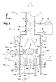
- each ventilation module 36 comprises a centrifugal wheel 44, or extraction wheel, for example a paddle wheel, which is rotatably mounted about a vertical axis, in the casing 38 associated, and which is adapted to be driven in rotation, for example by an associated actuator, such as an electric motor 46 shown schematically at the figure 2 .
- a centrifugal wheel 44 or extraction wheel, for example a paddle wheel, which is rotatably mounted about a vertical axis, in the casing 38 associated, and which is adapted to be driven in rotation, for example by an associated actuator, such as an electric motor 46 shown schematically at the figure 2 .
- the rotation of the wheel 44 creates a vacuum upstream of the wheel 44, to suck the outside air through the plenum 18, and an overpressure downstream of the wheel 44.
- the flow of air A flows from the plenum 18, after having been filtered by the filtering means 26a, 28a, 26b, 28b, and then flows through the intake collar 40 of each module of ventilation 36.
- the air flow A is blown into the heating zone 16b, through the first ventilation orifice 42a and the second ventilation orifice 42b of each ventilation module 36, in order to stir the air in the vicinity of the preforms.
- the plenum 18 has four ventilation modules 36; it is understood that this number could be different.
- furnace 10 comprises a series of plenum 18, here four in number, which are contiguous with each other and aligned in the longitudinal direction along their length, each plenum 18 having a series of four associated ventilation modules 36.
- the heating zone 16b is delimited transversely by a peripheral enclosure 54.
- the peripheral enclosure 54 comprises at least one so-called lower portion, comprising a first vertical lateral wall 54a and a second vertical lateral wall 54b which are arranged transversely opposite one another and each of which extends longitudinally, to delimit transversely between them, inside the furnace 10, the heating zone 16b.
- heating zone 16b is delimited longitudinally forwards by the front side 14 closed, and backwards by the rear side 12 open.
- Each side wall 54a, 54b of the peripheral enclosure 54 preferably comprises a plurality of doors 56, here four in number, which allow access to the interior of the furnace 10, for example to carry out control or control operations. maintenance inside the oven 10.
- Each door 56 comprises a ventilation grille 58 for allowing the flow of air A to flow from the outside of the oven 10 to the plenum 18 by suction.
- each ventilation grid 58 is arranged opposite an associated inlet mouth 22a, 22b, so that the passage of air flowing from the outside of the oven 10, to the the interior of the plenum 18 through the admission mouths 22a, 22b is little or not impeded by the grids 58.
- Each wall 54a, 54b of the peripheral enclosure 54 comprises a lower plate 60a, 60b respectively covering the furnace 10, which extends vertically substantially from the bottom of the doors 56 to the ground.
- the heating zone 16b is delimited vertically downwards by an upper face of the assembly constituted by the plenum 18, the intake ports 22a, 22b associated and the collectors 32 associated.
- peripheral enclosure 54 delimits, downstream, an upper opening 62, which opens vertically upwards, to allow the flow of air A to flow upwards.
- the upper opening 62 extends over the entire perimeter of the furnace 10, longitudinally from the rear side 12 to the front side 14 and transversely between the walls of the peripheral enclosure 54.
- the heating zone 16b includes lateral heating means 64 for the preforms, for example infrared radiation lamps which, when they are activated, irradiate the bodies of the preforms in order to heat them and bring them to a temperature suitable for their transformation in a container.
- lateral heating means 64 for the preforms for example infrared radiation lamps which, when they are activated, irradiate the bodies of the preforms in order to heat them and bring them to a temperature suitable for their transformation in a container.
- the infrared radiation lamps are for example superimposed in a rack (not shown) forming a heating module, heating modules being contiguous one after the other according to the running path of the preforms in the oven 10, so as to forming a first longitudinal section 64a of lamps and a second longitudinal section 64b lamps facing.
- the ventilation modules 36 are interposed transversely between the first longitudinal section 64a of lamps and the second longitudinal section 64b of lamps, so that the preforms pass between the lamps and the ventilation openings 42a, 42b of the ventilation modules 36.
- the air blown by the ventilation modules 36 preferably flows through perforated reflectors (not shown) which are arranged in the vicinity of the ventilation openings 42a, 42b. ventilation modules 36 and which comprise, for example, vertical orientation slots.
- the reflectors are arranged transversely vis-à-vis the heating means 64 and are intended to reflect the infrared radiation to increase the efficiency of heating, while allowing the passage of cooling air.
- the ventilation modules 36 stir the air which is situated in the vicinity of the heating means 64 and the preforms, in particular to avoid burning the skin of the body of the preforms and to homogenize the heating of the body of the preforms.
- the ventilation modules 36 create an overpressure in the heating zone 16b, in the vicinity of the preforms, which prevents any other air that filtered air does not come into contact with the preforms.
- the motor 46 which rotates the extraction wheel 44 of each ventilation module 36 cooperates with a first control means 29, to vary the speed of rotation of the wheels 44 and therefore vary the flow of air blown on preforms.
- the heating zone 16b includes thermal protection means (not shown) of the neck of the preforms to prevent their deformation by heating.
- the air extraction zone 16c of the oven 10 comprises a hood 66 which extends upwardly from the upper opening 62 of the heating zone 16b, to an extraction duct 68, so as to isolating the heating zone 16b from the outside of the furnace 10, to prevent pollution of the interior of the furnace 10 with airborne polluting particles.
- the hood 66 has a lower base of rectangular shape and has a flared shape towards the heating zone 16b, so a passage section decreasing upwards.
- the base of the hood 66 has two opposite longitudinal edges, generally rectilinear, which are connected to an upper edge of the side walls 54a, 54b respectively of the furnace 10.
- the hood 66 comprises a first plate 72 and a second upper horizontal plate 72 which are respectively contiguous to a first edge and to a second transverse edge of the base of the hood 66, in order to delimit the heating zone vertically. 16b of the oven 10.
- the first plate 70 and the second plate 72 are here each equipped with a inspection hatch (not shown), to access the inside of the oven 10 from the top of the oven 10, for example to perform maintenance tasks.
- the extraction duct 68 includes associated extraction means 74, for example a fan, which is capable of creating a vacuum upstream of the extraction means 74, in the extraction duct 68.
- associated extraction means 74 for example a fan, which is capable of creating a vacuum upstream of the extraction means 74, in the extraction duct 68.
- vacuum here means a pressure lower than the atmospheric pressure prevailing outside the furnace 10.
- the downstream end of the extraction duct 68 is for example connected to an evacuation circuit (not shown) which guides the air extracted from the furnace 10 into a space heating circuit, or outside the room in which is located the oven 10.
- the hood 66 delimits secondary or auxiliary air intake ports 76, which are arranged downstream of the heating zone 16b, so that an air flow B, referred to as leakage flow, flows through the inlet mouths of air 76 under the effect of the depression generated by the extraction means 74.
- the air of the leakage airflow B flows from the outside of the furnace 10, directly to the exhaust duct 68 of air, without passing through the sensitive heating zone 16b.
- Such a design promotes the entry of air through the air inlet ports 76, rather than through a parasitic air inlet, uncontrolled, without the risk of polluting the preforms or internal organs of the furnace 10 .
- the rate of extraction of air by the extraction duct 68 is greater than the filtered air flow sucked and ventilated by the ventilation modules 36, so as to evacuate all the ventilated cooling air and to guaranteeing that the air penetrating parasitically inside the furnace 10 due to the depression existing upstream of the extraction duct 68 penetrates exclusively through said secondary air inlet vents 76.
- the extraction means 74 is rotated by means of a second motor 78 which, depending on its operating speed, varies the speed of rotation of the extraction means 74 and therefore makes vary the depression downstream of the extraction means 74 and the flow of air extracted by the extraction means 74 through the extraction duct 68.
- the oven 10 comprises a second control means 80 of the extraction means 74, which cooperates with the second motor 78 to vary the operating speed.
- the furnace 10 comprises a first measurement means 82 of the depression within the extraction zone 16c of air, upstream of the extraction means 74.
- the measuring means 82 of the depression is here a differential pressure measuring means, or differential pressure transmitter, for example a piezoresistive pressure sensor.
- the measuring means 82 of the depression measures the pressure difference between the outside of the furnace 10 and a point located inside the hood 66, upstream of the extraction means 74 and downstream of the inlet mouths. associated air 76.
- the second control means 80 controls the extraction means 74 as a function of the value of the differential pressure measured by the measurement means 82 and of a setpoint depression value, in order to regulate the flow of air extracted by the means extraction 74 according to the associated setpoint value.
- the depression setpoint value is predetermined so as to create a depression within the hood 66, whereby the flow rate of air extracted through the extraction duct 68 is greater than the flow rate of air blown onto the preforms by the ducts 66. ventilation modules 36.
- the depression reference value is for example between 0 and 100 Pascals.
- control means 80 constitutes a means for controlling the ventilation modules 36 and the extraction means 74.
- the control means 80 makes it possible to obtain a constant flow rate of air, as a function of the depression setpoint value, independently of the fouling condition of the filtration means 26a, 28a, 26b, 28b.
- the oven 10 operates in a so-called production mode, in which the heating means 64 are activated, or in a so-called non-production mode, in which the heating means 64 are deactivated.
- the production mode corresponds to a normal preform heating operation, and the non-production mode corresponds to any other operating state of the oven 10, for example a standby mode of the oven 10, or a maintenance mode.
- the ventilation modules 36 and the extraction means 74 are rotated continuously, regardless of the mode in which the oven 10 operates, whereby the furnace 10 is permanently traversed by the airflow A cooling .
- the ventilation modules 36 are controlled by the associated control means 29, so that the air flow rate that is obtained thanks to the ventilation modules 36 is lower in the non-production mode than in the production mode of the oven 10.
- the depression setpoint value varies depending on the mode in which the oven operates, the depression setpoint value is lower when the oven 10 is operating in non-production mode.
- the vacuum set point value is determined so that the flow rate of the air flow extracted by the extraction means 74 is sufficient to extract the surplus heat in the furnace. 10.
- the first depression set point value is determined so that the flow rate of the air flow extracted by the extraction means 74 is sufficient to prevent any polluting particles of to be deposited on the preforms or on an internal member of the furnace 10, in particular the polluting particles which are sucked through the secondary air inlet mouths 76.
- the air intake zone 16a comprises means 84a, 86a for detecting the fouling of the filtering means 26a, 28a.
- the detection means 84a, 86a of the fouling comprise a second measurement means 84a of the depression, which is similar to the first measuring means 82 previously described.
- the second measuring means 84a measures the pressure difference between the outside of the furnace 10 and a point which is located between the pre-filter 26a and the filter 28a of the first air intake port 22a.
- the second measuring means 84a is able to measure the state of fouling, or clogging, of the pre-filter 26a by comparing the measured depression with a predetermined reference value.
- the fouling detection means 84a, 86a comprise a third measuring means 86a which measures the pressure difference between a point which is situated between the pre-filter 26a and the filter 28a, and a point which is situated directly downstream of the filter 28a of the first inlet mouth 22a.
- the third measuring means 86a is able to measure the state of fouling, or clogging, of the filter 28a by comparing the measured depression with a predetermined reference value.
- the air intake zone 16a comprises additional means (not shown) for detecting the fouling of the filtering means 26b, 28b of the second intake mouth 22b.
- the filtering means 26a, 28a, 26b, 28b are fouled, they are either cleaned and sterilized for example by means of steam, or replaced in whole or in part, the replaced parts being discarded and the others being cleaned.
- the furnace 10 comprises a first air flow measurement means which is arranged in the extraction duct 68, and a second air flow measurement means which is arranged in the plenum. 18.
- the first and the second means for measuring the air flow each cooperate with the second control means 80 of the extraction means 74, so that the flow rate of air that is extracted through the duct extraction 68 is greater than the air flow obtained thanks to the ventilation modules 36.
- the furnace 10 comprises sterilization or sanitization means (not shown) which are capable of emitting ultraviolet rays in order to irradiating internal furnace members that are likely to be in contact with the preform, for example the support means, or spinches, which cooperate with the inner wall of the neck of the preforms.
- sterilization or sanitization means (not shown) which are capable of emitting ultraviolet rays in order to irradiating internal furnace members that are likely to be in contact with the preform, for example the support means, or spinches, which cooperate with the inner wall of the neck of the preforms.
- the preforms are sterilized by means of a sterilizing agent, such as hydrogen peroxide deposited by condensation inside the preform, which agent evaporates when it is subjected to the heating means of the oven 10, then is sucked by the hood 66.
- a sterilizing agent such as hydrogen peroxide deposited by condensation inside the preform, which agent evaporates when it is subjected to the heating means of the oven 10, then is sucked by the hood 66.
- the plenum 18 is of a cylindrical shape with a vertical axis whose cylindrical wall constitutes a peripheral air inlet.
- each ventilation module 36 is connected directly to the collector 32 of the plenum, so that the casing 38 associated does not include an inlet collar 40, to further reduce the pressure drop between the plenum 18 and ventilation modules 36.
- each ventilation module 36 is connected directly to the plenum 18, without the intermediary of the collector 32.
- the invention also relates to an oven 10 which has no extraction means 74, and / or no ventilation module 36 for blowing the air on the preforms, the oven 10 being then for example crossed from upstream to downstream by a flow of cooling air flowing vertically to the extraction duct 68 by convection.
- the flow of the cooling air stream A through the furnace 10 can be initiated by any blowing or suction means, regardless of its arrangement in the furnace 10 or in the vicinity of the furnace 10.
- the cooling air flow A may be initiated by a blowing means which is arranged upstream of the plenum 18 and which makes it possible to blow air through the intake openings 22a, 22b of the plenum 18.
- the invention is not limited to an oven of generally parallelepiped shape, such as that described above.
- the invention is also applicable to an oven in the form of an arc, or circular, or annular, or any other form.
- the invention has many advantages, it allows in particular to reduce the pressure drop in the air circuit, from the outside of the furnace 10 to the ventilation modules 36.
- the plenum 18 is an air distribution chamber, or a supply of air, in which the associated ventilation modules 36 draw air with little or no loss of load.
- the plenum 18 constitutes a common distribution chamber, which makes it possible to overcome the constraint of connecting each ventilation module 36 to the outside of the oven 10 by means of an associated chimney duct.
- the plenum 18 is shaped to reduce the distance between the ventilation modules 36, and the air inlet, here the intake ports 22a, 22b.
- the plenum 18 extends vertically to the underside of the ventilation modules 36 and as close as possible to the ventilation modules 36, which makes it possible to dispense with all or part of the chimney ducts according to the state of the art. , thanks to which the pressure drops are reduced.
- the plenum 18 makes it possible to make best use of the useful volume of the intake zone 16a of the furnace 10, extending laterally as far as the walls of the furnace 10 and substantially as far as the ventilation modules 36.
- the plenum 18 offers an advantageous space / loss ratio.
- the design of the plenum 18 makes it possible to equip it with large intake openings and to increase the total filtering surface of the filtering means, by limiting the restrictions between the intake openings and the ventilation modules 36.
- the invention also relates to an oven which comprises a single ventilation module and an associated plenum of the type described above.
Landscapes
- Engineering & Computer Science (AREA)
- Manufacturing & Machinery (AREA)
- Mechanical Engineering (AREA)
- Physics & Mathematics (AREA)
- Thermal Sciences (AREA)
- Blow-Moulding Or Thermoforming Of Plastics Or The Like (AREA)
- Ventilation (AREA)
- Processing And Handling Of Plastics And Other Materials For Molding In General (AREA)
Abstract
Description
L'invention concerne un four pour le conditionnement thermique de préformes de récipients en matière thermoplastique qui comporte un plenum de ventilation.The invention relates to an oven for the thermal conditioning of thermoplastic container preforms which comprises a ventilation plenum.
L'invention concerne plus particulièrement un four pour le conditionnement thermique de préformes en matière thermoplastique, four qui est traversé d'amont en aval par un flux d'air de refroidissement des préformes et qui comporte, successivement selon le sens d'écoulement dudit flux d'air :
- une zone d'admission d'air qui comporte au moins une bouche d'admission d'air à travers laquelle ledit flux d'air s'écoule depuis l'extérieur du four, vers l'intérieur du four,
- une zone de chauffage des préformes, qui comporte des moyens de chauffage des préformes et au moins un module de ventilation qui est apte à guider vers les préformes le flux d'air provenant de la zone d'admission,
- une zone d'extraction d'air comportant au moins un conduit d'extraction d'air, la zone d'extraction étant traversée par le flux d'air qui s'écoule depuis la zone de chauffage, vers l'extérieur du four.
- an air intake zone which has at least one air intake port through which said air flow flows from the outside of the oven into the furnace interior,
- a preform heating zone, which comprises means for heating the preforms and at least one ventilation module which is capable of guiding the flow of air coming from the intake zone towards the preforms,
- an air extraction zone comprising at least one air extraction duct, the extraction zone being traversed by the flow of air flowing from the heating zone towards the outside of the oven.
La fabrication de récipients, tels que des flacons, des bouteilles, etc. en matière thermoplastique, par exemple en PET (polyéthylène téréphtalate), est généralement réalisée à partir de préformes obtenues par injection.The manufacture of containers, such as flasks, bottles, etc. thermoplastic material, for example PET (polyethylene terephthalate), is generally made from preforms obtained by injection.
De telles préformes sont préalablement conditionnées thermiquement dans un four afin de permettre leur transformation, notamment par une opération de soufflage, ou d'étirage-soufflage, en un récipient.Such preforms are preconditioned thermally in an oven to allow their transformation, in particular by a blowing operation, or stretch-blow molding, in a container.
Les préformes ont généralement une forme d'éprouvette comportant principalement un corps, plus ou moins long, et un col qui a déjà sa forme définitive. En effet, le col de la préforme forme le goulot du récipient et comporte par exemple un filetage destiné à recevoir un bouchon à vis.The preforms generally have a specimen shape mainly comprising a body, more or less long, and a neck that already has its final shape. Indeed, the neck of the preform forms the neck of the container and comprises for example a thread for receiving a screw cap.
Avant de réaliser l'opération de soufflage, il est nécessaire de chauffer le corps des préformes à une température supérieure à leur température de transition vitreuse, sans toutefois dégrader ou « brûler » la surface extérieure, ou peau, du corps des préformes.Before performing the blowing operation, it is necessary to heat the body of the preforms at a temperature above their glass transition temperature, without degrading or "burning" the outer surface, or skin, of the body of the preforms.
A cet effet, il est connu de soumettre les préformes, lorsqu'elles se trouvent dans la zone de chauffage, à un flux d'air de refroidissement circulant dans cette zone. Ceci à pour effet de favoriser la chauffe par rayonnement en modérant les effets de conduction thermique au travers de la masse d'air contenue dans le four.For this purpose, it is known to subject the preforms, when they are in the heating zone, to a flow of cooling air circulating in this zone. This has the effect of promoting radiation heating by moderating the effects of thermal conduction through the air mass contained in the oven.
On connaît, par exemple du document
Un tel four comporte principalement et successivement d'amont en aval selon le sens d'écoulement du flux d'air de refroidissement, une zone d'admission d'air, une zone de chauffage des préformes et une zone aval d'extraction d'air.Such an oven comprises mainly and successively from upstream to downstream according to the direction of flow of the cooling air flow, an air intake zone, a preform heating zone and a downstream extraction zone. air.
Les zones sont par exemple intégrées à l'intérieur du four et sont disposées de manière que l'extraction dans la zone d'extraction soit effectuée en partie haute ou supérieure du four, la zone de chauffage étant interposée entre la zone d'admission et la zone d'extraction.The zones are for example integrated inside the furnace and are arranged so that the extraction in the extraction zone is carried out at the upper or upper part of the furnace, the heating zone being interposed between the admission zone and the extraction zone.
La zone de chauffage est équipée de moyens de chauffage des préformes, par exemple des lampes à rayonnement infrarouge.The heating zone is equipped with means for heating the preforms, for example infrared radiation lamps.
Les moyens de chauffage sont alignés dans le four de façon à s'étendre le long de tout ou partie du trajet des préformes dans le four.The heating means are aligned in the oven so as to extend along all or part of the path of the preforms in the oven.
L'une des préoccupations de l'homme du métier est la maîtrise du conditionnement thermique des préformes dont dépend directement la qualité du récipient final obtenu et à laquelle l'efficacité du refroidissement, comme du chauffage, est également étroitement liée.One of the concerns of those skilled in the art is the control of the thermal conditioning of the preforms on which directly depends the quality of the final container obtained and to which the efficiency of cooling, such as heating, is also closely related.
Le four comporte une pluralité de modules de ventilation qui sont agencés dans la zone de chauffage du four et qui sont alignés en vis à vis des moyens de chauffage, afin de brasser l'air au voisinage des préformes.The oven comprises a plurality of ventilation modules which are arranged in the furnace heating zone and which are aligned with respect to the heating means, in order to mix the air in the vicinity of the preforms.
Les modules de ventilation ont pour fonction de modérer les effets de conduction thermique au travers de la masse d'air contenue dans le four et d'utiliser au maximum le rayonnement infrarouge des moyens de chauffage, afin de réchauffer au mieux l'épaisseur du corps des préformes sans en brûler la peau. Ceci permet d'éviter toute dégradation de la peau des préformes mais également de maintenir l'environnement de la zone de chauffage en deçà de températures susceptibles d'affecter les organes mécaniques s'y trouvant, tels que par exemple les culots des lampes à rayonnement infrarouge.The function of the ventilation modules is to moderate the effects of thermal conduction through the air mass contained in the oven and to make maximum use of the infrared radiation of the heating means, in order to warm up the thickness of the body as much as possible. preforms without burning the skin. This makes it possible to prevent any degradation of the skin of the preforms, but also to keep the environment of the heating zone below temperatures likely to affect the mechanical parts therein, such as, for example, the caps of the radiation lamps. infrared.
Chaque module de ventilation est raccordé à un conduit d'admission d'air tubulaire de section circulaire qui s'étend dans la zone d'admission du four et qui débouche à l'extérieur du four.Each ventilation module is connected to a tubular air intake duct of circular section which extends into the intake zone of the oven and which opens out of the oven.
De plus, chaque module de ventilation comporte une roue centrifuge montée rotative qui aspire l'air à travers le conduit d'admission et qui souffle l'air ainsi aspiré vers les préformes, de sorte que le flux d'air de refroidissement s'écoule au voisinage des préformes pour brasser l'air chaud au sein de la zone de chauffage du four.In addition, each fan module has a rotatably mounted centrifugal impeller that draws air through the intake duct and blows the air thus sucked into the preforms, so that the flow of cooling air flows. in the vicinity of the preforms to stir the hot air within the furnace heating zone.
Chaque roue centrifuge est agencée dans un carter qui guide le flux d'air de refroidissement vers les préformes.Each centrifugal wheel is arranged in a housing which guides the flow of cooling air to the preforms.
Grâce à la circulation du flux d'air de refroidissement, on exploite au mieux le rayonnement infrarouge, ce qui permet de porter à la température désirée le corps des préformes, de manière homogène sur l'épaisseur de la paroi du corps, sans détériorer la peau du corps des préformes ou encore ramollir le col des préformes.Thanks to the circulation of the cooling air flow, infrared radiation is best exploited, which enables the body of the preforms to be raised to the desired temperature. homogeneous way on the thickness of the wall of the body, without deteriorating the skin of the body of the preforms or soften the neck of the preforms.
Généralement, le four comporte des moyens de protection qui sont aptes à protéger les cols des préformes des rayonnements infrarouges, ainsi que des moyens dédiés au refroidissement des cols, lesquels sont par exemple constitués par une partie du flux d'air de refroidissement et/ou des moyens de refroidissement supplémentaires, notamment par circulation d'eau.Generally, the furnace comprises means of protection which are able to protect the necks of the preforms from infrared radiation, as well as means dedicated to the cooling of the necks, which are for example constituted by a part of the flow of cooling air and / or additional cooling means, in particular by circulation of water.
De façon complémentaire, la zone d'extraction d'air du four comporte des moyens d'extraction qui sont associés au conduit d'extraction, tels qu'une hotte d'extraction d'air.In a complementary manner, the furnace air extraction zone comprises extracting means which are associated with the extraction duct, such as an extractor hood.
La hotte surplombe la zone de chauffage, et elle est destinée à extraire vers l'extérieur, à travers le conduit d'extraction, l'air provenant de la zone de chauffage du four, notamment afin d'évacuer des calories du four.The hood overhangs the heating zone, and is intended to extract the air coming from the heating zone of the oven to the outside through the extraction duct, in particular in order to evacuate calories from the oven.
De tels moyens d'extraction permettent également de récupérer et d'évacuer des vapeurs résiduelles toxiques d'agent stérilisant lorsqu'une opération de décontamination de l'intérieur des préformes est mise en oeuvre simultanément au conditionnement thermique.Such extraction means also make it possible to recover and evacuate toxic residual vapors of sterilizing agent when a decontamination operation of the interior of the preforms is carried out simultaneously with the thermal conditioning.
Une telle opération de décontamination est avantageusement obtenue par le dépôt par condensation d'un agent stérilisant - comme le peroxyde d'hydrogène (H2O2) - destiné à être activé thermiquement dans le four par les moyens de chauffage puis évacué à l'état de vapeur par les moyens d'extraction d'air.Such a decontamination operation is advantageously obtained by the deposition by condensation of a sterilizing agent - such as hydrogen peroxide (H2O2) - intended to be activated thermally in the oven by the heating means and then discharged in the vapor state. by the air extraction means.
Une autre préoccupation de l'homme du métier concerne d'une manière générale l'hygiène et la propreté des récipients, donc la propreté des préformes destinées à être transformées en récipients après chauffage par soufflage (ou étirage-soufflage), les récipients étant ensuite de préférence remplis directement en milieu aseptique après leur fabrication.Another concern of those skilled in the art generally relates to the hygiene and cleanliness of the containers, thus the cleanliness of the preforms intended to be transformed into containers after heating by blow molding (or stretch-blow molding), the containers being then preferably filled directly into an aseptic medium after their manufacture.
Comme indiqué précédemment, il est connu de stériliser l'intérieur des préformes au moyen d'agent, tel que le peroxyde d'hydrogène, lequel s'évapore lorsqu'il est soumis aux moyens de chauffage du four, puis est aspiré par la hotte.As indicated previously, it is known to sterilize the interior of the preforms by means of an agent, such as hydrogen peroxide, which evaporates when it is subjected to the heating means of the oven and is then sucked by the hood .
Complémentairement, il est connu de décontaminer l'extérieur de la préforme, notamment le col, par une irradiation aux rayons ultra-violets.Complementarily, it is known to decontaminate the outside of the preform, in particular the neck, by ultraviolet irradiation.
Enfin, il est connu d'équiper l'extrémité libre de chaque conduit d'admission par une bouche d'admission dans laquelle sont agencés des moyens de filtration de l'air, de sorte que les modules de ventilation délivrent aux préformes un air filtré présentant un degré de propreté déterminé.Finally, it is known to equip the free end of each intake duct by an inlet mouth in which air filtering means are arranged, so that the ventilation modules deliver to the preforms a filtered air. having a certain degree of cleanliness.
Toutefois, la qualité de l'air ventilé dépend de l'efficacité des filtres.However, the quality of the ventilated air depends on the efficiency of the filters.
Or, plus les filtres sont efficaces et plus ils s'opposent au passage de l'air et créent ainsi une perte de charge importante dans le circuit de ventilation.However, the more efficient the filters, the more they oppose the passage of air and thus create a significant pressure drop in the ventilation circuit.
Une perte de charge est préjudiciable au bon fonctionnement du four puisqu'elle se traduit par une diminution du débit d'air soufflé vers les préformes par les modules de ventilation et donc par une baisse des performances du refroidissement de l'air au voisinage des préformes.A pressure drop is detrimental to the proper functioning of the furnace since it results in a decrease in the flow of air blown to the preforms by the ventilation modules and therefore in a drop in air cooling performance in the vicinity of the preforms .
L'invention vise notamment à améliorer encore la propreté des préformes, et donc des récipients, sans toutefois altérer ni le conditionnement thermique des préformes opéré dans le four, ni le débit d'air ventilé sur les préformes par les modules de ventilation.The invention aims in particular to further improve the cleanliness of the preforms, and therefore the containers, without however altering the thermal conditioning of the preforms operated in the furnace, nor the flow of ventilated air on the preforms by the ventilation modules.
Dans ce but, l'invention propose notamment de favoriser la qualité de filtration des moyens de filtration, tout en limitant les pertes de charges dans le circuit d'admission d'air, ou de refroidissement.For this purpose, the invention proposes in particular to promote the filtration quality of the filtration means, while limiting the pressure losses in the air intake circuit, or cooling.
L'invention propose plus particulièrement un four du type décrit précédemment, caractérisé en ce que la zone d'admission d'air comporte :
- au moins deux modules de ventilation, et
- au moins une chambre de répartition d'air, dite plenum, qui est interposée entre la bouche d'admission d'air et chacun des modules de ventilation, chaque module de ventilation étant relié à la chambre de répartition.
- at least two ventilation modules, and
- at least one air distribution chamber, called plenum, which is interposed between the air intake opening and each of the ventilation modules, each ventilation module being connected to the distribution chamber.
Grâce à la chambre de répartition d'air, on augmente le rapport de la qualité de filtration de l'air aspiré par rapport à la perte de charge.Thanks to the air distribution chamber, it increases the ratio of the filtration quality of the air sucked in relation to the pressure drop.
En effet, une telle chambre de répartition délimite un volume commun important d'air filtré dans lequel chaque module de ventilation puise de l'air filtré, grâce à quoi les pertes de charge sont réduites.Indeed, such a distribution chamber defines a large common volume of filtered air in which each ventilation module draws filtered air, whereby the pressure losses are reduced.
De plus, une telle chambre de répartition, grâce à son volume et à sa compacité, permet de limiter les étranglements dans le circuit de refroidissement, lesquels s'opposent à l'écoulement du flux d'air de refroidissement et favorisent les pertes de charge.In addition, such a distribution chamber, thanks to its volume and its compactness, makes it possible to limit the restrictions in the cooling circuit, which oppose the flow of the cooling air flow and favor the pressure losses. .
Selon d'autres caractéristiques de l'invention :
- chaque module de ventilation comporte une roue qui est montée rotative de façon à aspirer l'air contenu dans la chambre de répartition et à souffler l'air ainsi aspiré vers les préformes ;
- la chambre de répartition est de la forme d'un caisson parallélépipédique comportant au moins :
- -- une première grande face latérale ouverte qui comporte une première bouche d'admission d'air,
- -- une seconde grande face latérale ouverte qui est opposée et parallèle à la première grande face et qui comporte une seconde bouche d'admission d'air ;
- chaque bouche d'admission d'air comporte des moyens de filtration d'air associés ;
- chacun des moyens de filtration comporte successivement au moins :
- -- un pré-filtre amont qui est apte à filtrer des particules d'un premier diamètre déterminé, et
- -- un filtre aval qui est apte à filtrer des particules d'un second diamètre inférieur audit premier diamètre déterminé ;
- chaque pré-filtre amont est un filtre gravimétrique ;
- chaque bouche d'admission est d'une forme évasée vers l'extérieur du four, chaque pré-filtre amont étant agencé dans le tronçon le plus large de la bouche d'admission associée, en amont du filtre aval associé, de sorte que la section de passage de chaque pré-filtre amont est supérieure à la section de passage du filtre aval associé ;
- la chambre de répartition comporte une grande face qui s'étend orthogonalement auxdites grandes faces latérales, et sur laquelle est relié un collecteur d'air qui relie sélectivement chaque module de ventilation à la chambre de répartition ;
- la zone d'admission comporte des moyens de détection de l'encrassement desdits moyens de filtration, lesdits moyens de détection étant aptes à mesurer :
- -- une première pression différentielle entre un point situé directement en amont du pré-filtre et un point situé directement en aval du pré-filtre de la première bouche d'admission, et
- -- une seconde pression différentielle entre un point situé directement en amont du filtre et un point situé directement en aval du filtre de la première bouche d'admission,
- -- et à comparer chaque pression différentielle à une valeur prédéterminée de pression respective, grâce à quoi il est possible d'évaluer individuellement les états respectifs d'encrassement du pré-filtre et du filtre.
- each ventilation module comprises a wheel which is rotatably mounted so as to suck the air contained in the distribution chamber and to blow the air thus sucked towards the preforms;
- the distribution chamber is in the form of a parallelepipedic box comprising at least:
- a first large open lateral face which comprises a first air inlet mouth,
- a second large open lateral face which is opposite and parallel to the first large face and which comprises a second air intake mouth;
- each air intake mouth comprises associated air filtration means;
- each of the filtration means comprises successively at least:
- an upstream pre-filter which is capable of filtering particles of a first determined diameter, and
- a downstream filter which is capable of filtering particles of a second diameter smaller than said first determined diameter;
- each upstream pre-filter is a gravimetric filter;
- each inlet mouth is of a flared shape towards the outside of the furnace, each upstream pre-filter being arranged in the widest section of the associated inlet mouth, upstream of the associated downstream filter, so that the passage section of each upstream pre-filter is greater than the cross section of the associated downstream filter;
- the distribution chamber has a large face which extends orthogonally to said large side faces, and on which is connected an air collector which selectively connects each ventilation module to the distribution chamber;
- the intake zone comprises means for detecting the fouling of said filtering means, said detection means being able to measure:
- a first differential pressure between a point situated directly upstream of the pre-filter and a point situated directly downstream of the pre-filter of the first intake mouth, and
- a second differential pressure between a point situated directly upstream of the filter and a point situated directly downstream of the filter of the first intake mouth,
- and comparing each differential pressure with a predetermined value of respective pressure, whereby it is possible to evaluate individually the respective states of fouling of the pre-filter and the filter.
D'autres caractéristiques et avantages de l'invention, ainsi que des détails de conception et de réalisation apparaîtront à la lecture de la description détaillée qui va suivre pour la compréhension de laquelle on se reportera aux dessins annexés dans lesquels :
- la
figure 1 est une vue d'ensemble en perspective, qui illustre un exemple de réalisation d'un four selon l'invention, comportant successivement une zone d'admission d'air, une zone de chauffage des préformes et une zone d'extraction d'air ; - la
figure 2 est une vue schématique en section transversale, qui illustre l'écoulement, d'amont en aval, d'un flux d'air de refroidissement à travers les zones du four de lafigure 1 et une chambre de répartition du flux d'air de refroidissement reliée à une pluralité de modules de ventilation ; - la
figure 3 est une vue schématique en section longitudinale, qui illustre l'agencement d'une pluralité de chambres de répartition dans la zone d'admission du four de lafigure 1 ; - la
figure 4 est une vue de détail en perspective, qui illustre une chambre de répartition équipée de deux bouches d'admission et un collecteur auquel sont reliés les modules de ventilation du four de lafigure 1 ; - la
figure 5 est une vue de détail en section et en perspective, qui illustre des moyens de filtration agencés à l'intérieur de la chambre de répartition et une roue centrifuge agencée dans un module de ventilation du four de lafigure 1 .
- the
figure 1 is an overall perspective view, which illustrates an embodiment of a furnace according to the invention, successively comprising an air intake zone, a preform heating zone and an air extraction zone. ; - the
figure 2 is a schematic cross-sectional view illustrating the flow, from upstream to downstream, of a flow of cooling air through the furnace zones of thefigure 1 and a cooling air flow distribution chamber connected to a plurality of ventilation modules; - the
figure 3 is a schematic view in longitudinal section, which illustrates the arrangement of a plurality of distribution chambers in the furnace inlet zone of thefigure 1 ; - the
figure 4 is a detail view in perspective, which illustrates a distribution chamber equipped with two intake ports and a manifold to which are connected the ventilation modules of the oven of thefigure 1 ; - the
figure 5 is a detail view in section and in perspective, which illustrates filtration means arranged inside the distribution chamber and a centrifugal wheel arranged in a ventilation module of the furnace of thefigure 1 .
Dans la description et les revendications, on adoptera par convention et à titre non limitatif les termes "avant" ou "arrière" en référence à la direction longitudinale, "supérieur" et "inférieur", en référence à la direction verticale et selon la gravité terrestre, et les directions longitudinale, verticale et transversale en référence aux trièdres (L, V, T) indiqués sur les figures.In the description and the claims, the terms "front" or "rear" will be adopted by convention and in a nonlimiting manner with reference to the longitudinal direction, "upper" and "lower", with reference to the vertical direction and according to the gravity terrestrial, and the longitudinal, vertical and transverse directions with reference to the trihedrons (L, V, T) indicated in the figures.
On utilisera aussi les expressions "amont" et "aval" en référence au sens de circulation du flux d'air de refroidissement à l'intérieur du four, c'est-à-dire depuis la zone d'admission, dite amont, vers la zone d'extraction, dite aval, du four.The terms "upstream" and "downstream" will also be used with reference to the flow direction of the cooling air flow inside the oven, that is to say from the so-called upstream admission zone the extraction zone, called downstream, of the furnace.
On a représenté à la
Le four 10 comporte par exemple ici un parcours de chauffe des préformes en « U » comportant deux tronçons longitudinaux de chauffage parallèles, l'un aller, l'autre retour, raccordés entre eux un tronçon curviligne transversal, dit de stabilisation.The
Le four 10 a globalement la forme d'un tunnel qui s'étend longitudinalement, d'arrière en avant, depuis un premier côté arrière 12, jusqu'à un second côté avant 14 opposé fermé.The
Le côté arrière 12 est ouvert pour permettre le passage des préformes. Toutefois, il est ouvert dans une zone en surpression, comme il sera décrit ultérieurement, de sorte que des particules polluantes ne peuvent pas pénétrer dans le four par ce côté arrière 12.The
Comme on peut le voir à la
Le four 10 n'est que l'un des postes d'une installation de fabrication de récipients, par exemple de bouteilles, à partir de préformes.The
Une telle installation de fabrication comporte par exemple un dispositif d'alimentation (non représenté) en préformes, qui alimente le four 10 en préformes par le côté arrière 12 du four 10.Such a manufacturing facility comprises for example a feeding device (not shown) in preforms, which feeds the
Les préformes sont introduites à l'intérieur du four 10 par des moyens de transfert au niveau du côté arrière 12 où les préformes sont prises en charge par des moyens de convoyage du four 10, opération encore appelée « vêtissage ».The preforms are introduced inside the
Les préformes sont ensuite entraînées dans le four 10 par les moyens de convoyage (non représentés), par exemple ici suivant un parcours de chauffe en U.The preforms are then entrained in the
Enfin, les préformes ressortent du four 10 à travers le côté arrière 12 et sont, après avoir été conditionnées thermiquement par le four 10, prises en charge par d'autres moyens de transfert (non représentés) pour les acheminer directement vers un dispositif de moulage (non représenté) en vue de leur transformation par soufflage, ou par étirage-soufflage en un récipient.Finally, the preforms emerge from the
Avantageusement, les moyens de convoyage des préformes sont aptes à transporter les préformes suivant le parcours de chauffe et comportent des éléments de support (non représentés), encore appelés parfois « tournettes », dont chacun coopère avec la paroi interne du goulot de chaque préforme.Advantageously, the conveying means of the preforms are capable of transporting the preforms along the heating path and comprise support elements (not shown), also sometimes called "spinners", each of which cooperates with the inner wall of the neck of each preform.
De préférence, les éléments de support des moyens de convoyage sont aptes à entraîner en rotation sur elle-méme chaque préforme afin de favoriser une répartition appropriée de la chaleur dans le corps de chaque préforme.Preferably, the support elements of the conveying means are able to rotate each of the preforms in rotation in order to promote an appropriate distribution of heat in the body of each preform.
Selon la
Comme on peut le voir aux
Les trois zones 16a, 16b, 16c sont ici superposées verticalement et l'écoulement du flux d'air A s'effectue successivement à travers chaque zone, depuis le bas vers le haut, c'est-à-dire également suivant un gradient thermique depuis la zone la plus froide vers la zone la plus chaude.The three
Avantageusement, un tel agencement des zones du circuit de refroidissement permet d'obtenir un four présentant une bonne compacité et d'exploiter le principe de convection.Advantageously, such an arrangement of the zones of the cooling circuit makes it possible to obtain an oven having good compactness and to exploit the principle of convection.
La zone d'admission 16a d'air comporte au moins une chambre de répartition d'air 18, dite plenum, qui est ici de la forme d'un caisson parallélépipédique à travers lequel le flux d'air A de refroidissement s'écoule depuis l'extérieur du four 10, vers l'intérieur du four 10.The
A cet effet, comme on peut le voir à la
La bouche d'admission 22a s'étend transversalement depuis le plenum 18 et est d'une forme évasée, de section transversale croissante vers l'extérieur du four 10.The
Selon les
Selon la
De préférence, le pré-filtre 26a est un filtre gravimétrique, qui est apte à filtrer des particules dites grossières, qui sont d'un diamètre déterminé, par exemple supérieur à dix microns.Preferably, the pre-filter 26a is a gravimetric filter, which is capable of filtering said coarse particles, which are of a determined diameter, for example greater than ten microns.
De même, le filtre 28a est un filtre du type dit « opacimétrique », qui est apte à filtrer des particules dites fines d'un diamètre déterminé, par exemple supérieur à un micron.Similarly, the
Par symétrie selon le plan de symétrie générale, le plenum 18 comporte une seconde grande face 20b verticale longitudinale qui est agencée en vis à vis de la première grande face 20a qui est équipée d'une seconde bouche d'admission 22b d'air.By symmetry according to the general plane of symmetry, the
De même, la bouche d'admission 22b comporte des seconds moyens de filtration 26b, 28b avec un pré-filtre 26b et un filtre 28b.Similarly, the
Ainsi, chaque bouche d'admission 22a, 22b est équipée de moyens de filtration de l'air aspiré, de sorte que seul de l'air filtré, avec un degré de propreté déterminé, est aspiré et introduit dans la zone d'admission 16a du four 10.Thus, each
Le plenum 18 comporte une troisième grande face 30 supérieure horizontale, sur laquelle est relié un collecteur 32 d'air qui s'étend longitudinalement sur toute la longueur du plenum 18.The
Le collecteur 32 est d'une section transversale trapézoïdale décroissante vers le haut, et il est délimité vers le haut par une face supérieure 34 de répartition.The
De plus, le plenum 18 est délimité longitudinalement par une première plaque transversale verticale 48 et par une seconde plaque transversale verticale 50 opposée à la première plaque transversale verticale 48.In addition, the
Enfin, le plenum 18 est délimité verticalement vers le bas par une plaque de fond 52 longitudinale transversale.Finally, the
Selon les
L'ensemble constitué par le plenum 18, les deux bouches d'admission 22a, 22b et le collecteur 32, délimite un volume important d'air filtré et des grandes entrées d'air, grâce à quoi les pertes de charge dans le circuit de refroidissement 16 sont limitées.The assembly constituted by the
La zone de chauffage 16b du four 10 comporte des modules de ventilation 36, tels que des ventilateurs centrifuges de refroidissement qui sont alignés selon un axe longitudinal au dessus du collecteur 32 du plenum 18.The
Chaque module de ventilation 36 comporte un carter 38 délimitant un collier d'admission 40 inférieur vertical qui est raccordé à la face supérieure 34 de répartition du collecteur 32.Each
De plus, chaque carter 38 délimite un premier orifice de ventilation 42a et un second orifice de ventilation 42b.In addition, each
Enfin, chaque module de ventilation 36 comporte une roue 44 centrifuge, ou d'extraction, par exemple une roue à aubes, qui est montée tournante autour d'un axe vertical, dans le carter 38 associé, et qui est apte à être entraînée en rotation, par exemple par un actionneur associé, comme un moteur 46 électrique représenté schématiquement à la
La rotation de la roue 44 créé une dépression en amont de la roue 44, pour aspirer l'air extérieur à travers le plenum 18, et une surpression en aval de la roue 44.The rotation of the
Ainsi, le flux d'air A s'écoule depuis le plenum 18, après avoir été filtré par les moyens de filtration 26a, 28a, 26b, 28b, puis il s'écoule à travers le collier d'admission 40 de chaque module de ventilation 36.Thus, the flow of air A flows from the
Enfin, le flux d'air A est soufflé dans la zone de chauffage 16b, à travers le premier orifice de ventilation 42a et le second orifice de ventilation 42b de chaque module de ventilation 36, afin de brasser l'air au voisinage des préformes.Finally, the air flow A is blown into the
Selon l'exemple de réalisation illustré aux
De plus, selon la
Comme on peut le voir sur les
L'enceinte périphérique 54 comporte au moins une partie, dite inférieure, comportant une première paroi 54a latérale verticale et une seconde paroi 54b latérale verticale qui sont agencées transversalement en vis à vis et dont chacune s'étend longitudinalement, pour délimiter transversalement entre elles, à l'intérieur du four 10, la zone de chauffage 16b.The
De plus, la zone de chauffage 16b est délimitée longitudinalement vers l'avant par le côté avant 14 fermé, et vers l'arrière par le côté arrière 12 ouvert.In addition, the
Chaque paroi 54a, 54b latérale de l'enceinte périphérique 54 comporte de préférence une pluralité de portes 56, ici au nombre de quatre, qui permettent d'accéder à l'intérieur du four 10, par exemple pour exécuter des opérations de contrôle ou de maintenance à l'intérieur du four 10.Each
Chaque porte 56 comporte une grille 58 d'aération pour permettre l'écoulement du flux d'air A par aspiration, depuis l'extérieur du four 10, jusqu'au plenum 18.Each
Comme on peut le voir à la
Chaque paroi 54a, 54b de l'enceinte périphérique 54 comporte une plaque inférieure 60a, 60b respectivement d'habillage du four 10, qui s'étend verticalement sensiblement du bas des portes 56 jusqu'au sol.Each
Selon les
Enfin, l'enceinte périphérique 54 délimite, en aval, une ouverture supérieure 62, qui débouche verticalement vers le haut, pour permettre au flux d'air A de s'écouler vers le haut.Finally, the
L'ouverture supérieure 62 s'étend sur tout le périmètre du four 10, longitudinalement depuis le côté arrière 12 jusqu'au côté avant 14 et transversalement entre les parois de l'enceinte périphérique 54.The
Selon la
Les lampes à rayonnement infrarouge sont par exemple superposées dans un râtelier (non représenté) formant un module de chauffage, des modules de chauffage étant accolés les uns à la suite des autres selon le parcours de défilement des préformes dans le four 10, de façon à former un premier tronçon 64a longitudinal de lampes et un second tronçon 64b longitudinal de lampes en vis à vis.The infrared radiation lamps are for example superimposed in a rack (not shown) forming a heating module, heating modules being contiguous one after the other according to the running path of the preforms in the
Comme on peut le voir à la
L'air soufflé par les modules de ventilation 36 s'écoule de préférence à travers des réflecteurs (non représentés) ajourés qui sont agencés au voisinage des orifices de ventilation 42a, 42b des modules de ventilation 36 et qui comportent par exemple des fentes d'orientation verticales.The air blown by the
Les réflecteurs sont disposés transversalement en vis-à-vis des moyens de chauffage 64 et sont destinés à réfléchir les rayonnements infrarouges pour accroître l'efficacité du chauffage, tout en permettant le passage de l'air de refroidissement.The reflectors are arranged transversely vis-à-vis the heating means 64 and are intended to reflect the infrared radiation to increase the efficiency of heating, while allowing the passage of cooling air.
Ainsi, les modules de ventilation 36 brassent l'air qui est situé au voisinage des moyens de chauffage 64 et des préformes, afin notamment d'éviter de brûler la peau du corps des préformes et d'homogénéiser la chauffe du corps des préformes.Thus, the
De plus, les modules de ventilation 36 créent une surpression dans la zone de chauffage 16b, au voisinage des préformes, ce qui empêche que tout autre air que de l'air filtré n'entre en contact avec les préformes.In addition, the
Le moteur 46 qui entraîne en rotation la roue 44 d'extraction de chaque module de ventilation 36 coopère avec un premier moyen de pilotage 29, pour faire varier la vitesse de rotation des roues 44 et par conséquent faire varier le débit d'air soufflé sur les préformes.The
Avantageusement, la zone de chauffage 16b comporte des moyens de protection thermique (non représentés) du col des préformes pour éviter leur déformation par chauffage.Advantageously, the
Enfin, selon les
La hotte 66 comporte une embase inférieure de forme rectangulaire et présente une forme évasée vers la zone de chauffage 16b, donc une section de passage décroissante vers le haut.The
L'embase de la hotte 66 comporte deux bords longitudinaux opposés, globalement rectilignes, qui sont reliés à un bord supérieur des parois 54a, 54b latérales respectivement du four 10.The base of the
De façon complémentaire, la hotte 66 comporte une première plaque 70 et une seconde plaque 72 horizontales supérieures qui sont respectivement accolées à un premier bord et à un second bord transversal de l'embase de la hotte 66, afin de délimiter verticalement la zone de chauffage 16b du four 10.In a complementary manner, the
La première plaque 70 et la seconde plaque 72 sont ici chacune équipée d'une trappe de visite (non représentée), pour accéder à l'intérieur du four 10 depuis le dessus du four 10, par exemple pour exécuter des tâches de maintenance.The
Le conduit d'extraction 68 comporte un moyen d'extraction 74 associé, par exemple un ventilateur, qui est apte à créer une dépression en amont du moyen d'extraction 74, dans le conduit d'extraction 68.The
Le terme dépression signifie ici une pression inférieure à la pression atmosphérique qui règne à l'extérieur du four 10.The term "vacuum" here means a pressure lower than the atmospheric pressure prevailing outside the
Ainsi, le flux d'air A s'écoule depuis l'intérieur du four 10, vers l'extérieur du four 10, selon le sens des flèches représentées aux
L'extrémité aval du conduit d'extraction 68 est par exemple raccordée à un circuit d'évacuation (non représenté) qui guide l'air extrait du four 10 dans un circuit de chauffage de locaux, ou à l'extérieur du local dans lequel est situé le four 10.The downstream end of the
Partant de l'hypothèse que le four 10 n'est pas parfaitement étanche à l'air, et que le moyen d'extraction 68 d'extraction engendre une dépression au sein du four 10, des filets d'air parasites risquent de pénétrer dans le four 10, notamment autour des portes 56.On the assumption that the
Pour éviter la pénétration à l'intérieur du four 10 de tels filets d'air dont la qualité est incontrôlée, la hotte 66 délimite des bouches d'entrée d'air 76 secondaires, ou auxiliaires, qui sont agencées en aval de la zone de chauffage 16b, de sorte qu'un flux d'air B, dit de fuite, s'écoule à travers les bouches d'entrée d'air 76 sous l'effet de la dépression engendrée par le moyen d'extraction 74.To prevent the penetration into the
Ainsi, l'air du flux d'air B de fuite s'écoule depuis l'extérieur du four 10, directement jusqu'au conduit d'extraction 68 d'air, sans passer par la zone sensible de chauffage 16b.Thus, the air of the leakage airflow B flows from the outside of the
Une telle conception favorise l'entrée d'air à travers les bouches d'entrée d'air 76, plutôt qu'à travers une entrée d'air parasite, non contrôlée, sans risquer de polluer les préformes ou des organes internes du four 10.Such a design promotes the entry of air through the
Avantageusement, le débit d'extraction d'air par le conduit d'extraction 68 est supérieur au débit d'air filtré aspiré et ventilé par les modules de ventilation 36, de manière à évacuer la totalité de l'air de refroidissement ventilé et à garantir que l'air pénétrant de façon parasite à l'intérieur du four 10 en raison de la dépression existant en amont du conduit d'extraction 68 pénètre exclusivement par lesdites bouches d'entrée d'air 76 secondaire.Advantageously, the rate of extraction of air by the
Selon un autre aspect, le moyen d'extraction 74 est entraîné en rotation au moyen d'un second moteur 78 qui, en fonction de son régime de fonctionnement, fait varier la vitesse de rotation du moyen d'extraction 74 et par conséquent, fait varier la dépression en aval du moyen d'extraction 74 et le débit d'air extrait par le moyen d'extraction 74 à travers le conduit d'extraction 68.In another aspect, the extraction means 74 is rotated by means of a
A cet effet, selon la
De plus, le four 10 comporte un premier moyen de mesure 82 de la dépression au sein de la zone d'extraction 16c d'air, en amont du moyen d'extraction 74.In addition, the
Comme on peut le voir à la
Le moyen de mesure 82 de la dépression mesure la différence de pression entre l'extérieur du four 10 et un point situé à l'intérieur de la hotte 66, en amont du moyen d'extraction 74 et en aval des bouches d'entrée d'air 76 associées.The measuring means 82 of the depression measures the pressure difference between the outside of the
Le second moyen de pilotage 80 pilote le moyen d'extraction 74 en fonction de la valeur de la pression différentielle mesurée par le moyen de mesure 82 et d'une valeur consigne de dépression, afin de réguler le débit d'air extrait par le moyen d'extraction 74 suivant la valeur consigne associée.The second control means 80 controls the extraction means 74 as a function of the value of the differential pressure measured by the measurement means 82 and of a setpoint depression value, in order to regulate the flow of air extracted by the
La valeur consigne de dépression est prédéterminée de manière à créer une dépression au sein de la hotte 66, grâce à quoi le débit d'air extrait à travers le conduit d'extraction 68 est supérieur au débit d'air soufflé sur les préformes par les modules de ventilation 36.The depression setpoint value is predetermined so as to create a depression within the
La valeur consigne de dépression est par exemple comprise entre 0 et 100 Pascals.The depression reference value is for example between 0 and 100 Pascals.
Ainsi, le moyen de pilotage 80 constitue un moyen d'asservissement des modules de ventilation 36 et du moyen d'extraction 74.Thus, the control means 80 constitutes a means for controlling the
Le moyen de pilotage 80 permet d'obtenir un débit constant d'air, en fonction de la valeur consigne de dépression, indépendamment de l'état d'encrassement des moyens de filtration 26a, 28a, 26b, 28b.The control means 80 makes it possible to obtain a constant flow rate of air, as a function of the depression setpoint value, independently of the fouling condition of the filtration means 26a, 28a, 26b, 28b.
Le four 10 fonctionne selon un mode dit de production, dans lequel les moyens de chauffage 64 sont activés, ou selon un mode dit hors production, dans lequel les moyens de chauffage 64 sont désactivés.The
Le mode de production correspond à un fonctionnement normal de chauffage des préformes, et le mode hors production correspond à tout autre état de fonctionnement du four 10, par exemple un mode de veille du four 10, ou un mode de maintenance.The production mode corresponds to a normal preform heating operation, and the non-production mode corresponds to any other operating state of the
Les modules de ventilation 36 et le moyen d'extraction 74 sont entraînés en rotation en permanence, quel que soit le mode selon lequel le four 10 fonctionne, grâce à quoi le four 10 est traversé en permanence par le flux d'air A de refroidissement.The
Ainsi, seul de l'air filtré s'écoule à travers la zone de chauffage 16b, empêchant ainsi le dépôt de particules polluantes sur les préformes ou des organes internes du four 10.Thus, only filtered air flows through the
De plus, les modules de ventilation 36 sont pilotés par le moyen de pilotage 29 associé, de sorte que le débit d'air qui est obtenu grâce aux modules de ventilation 36 est inférieur en mode hors production qu'en mode production du four 10.In addition, the
De même, la valeur consigne de dépression varie en fonction du mode selon lequel le four fonctionne, la valeur consigne de dépression étant moins grande lorsque le four 10 fonctionne en mode hors production.Similarly, the depression setpoint value varies depending on the mode in which the oven operates, the depression setpoint value is lower when the
Plus particulièrement, lorsque le four 10 fonctionne selon son mode hors production, la valeur consigne de dépression est déterminée de sorte que le débit du flux d'air extrait par le moyen d'extraction 74 est suffisant pour extraire le surplus de chaleur dans le four 10.More particularly, when the
De même, lorsque le four 10 fonctionne selon son mode hors production, la première valeur consigne de dépression est déterminée de sorte que le débit du flux d'air extrait par le moyen d'extraction 74 est suffisant pour empêcher que des éventuelles particules polluantes de se déposer sur les préformes ou sur un organe interne du four 10, notamment les particules polluantes qui sont aspirées à travers les bouches d'entrée d'air 76 secondaire.Likewise, when the
Selon un autre aspect, la zone d'admission 16a d'air comporte des moyens 84a, 86a de détection de l'encrassement des moyens de filtration 26a, 28a.In another aspect, the
Les moyens de détection 84a, 86a de l'encrassement comportent un second moyen de mesure 84a de la dépression, qui est similaire au premier moyen de mesure 82 décrit précédemment.The detection means 84a, 86a of the fouling comprise a second measurement means 84a of the depression, which is similar to the first measuring means 82 previously described.
Le second moyen de mesure 84a, illustré schématiquement à la
Ainsi, le second moyen de mesure 84a est apte à mesurer l'état d'encrassement, ou de colmatage, du pré-filtre 26a par comparaison de la dépression mesurée avec une valeur de référence prédéterminée.Thus, the second measuring means 84a is able to measure the state of fouling, or clogging, of the pre-filter 26a by comparing the measured depression with a predetermined reference value.
De même, les moyens de détection 84a, 86a de l'encrassement comportent un troisième moyen de mesure 86a qui mesure la différence de pression entre un point qui est situé entre le pré-filtre 26a et le filtre 28a, et un point qui est situé directement en aval du filtre 28a de la première bouche d'admission 22a.Similarly, the fouling detection means 84a, 86a comprise a third measuring means 86a which measures the pressure difference between a point which is situated between the pre-filter 26a and the
Ainsi, le troisième moyen de mesure 86a est apte à mesurer l'état d'encrassement, ou de colmatage, du filtre 28a par comparaison de la dépression mesurée avec une valeur de référence prédéterminée.Thus, the third measuring means 86a is able to measure the state of fouling, or clogging, of the
Par symétrie, la zone d'admission 16a d'air comporte des moyens supplémentaires (non représentés) de détection de l'encrassement des moyens de filtration 26b, 28b de la seconde bouche d'admission 22b.By symmetry, the
Lorsque les moyens de filtration 26a, 28a, 26b, 28b sont encrassés, ils sont soit nettoyés et stérilisés par exemple au moyen de vapeur d'eau, soit remplacés en tout ou partie, les parties remplacées étant alors jetées et les autres étant nettoyées.When the filtering means 26a, 28a, 26b, 28b are fouled, they are either cleaned and sterilized for example by means of steam, or replaced in whole or in part, the replaced parts being discarded and the others being cleaned.
Selon une variante de réalisation non représentée, le four 10 comporte un premier moyen de mesure du débit d'air qui est agencé dans le conduit d'extraction 68, et un second moyen de mesure du débit d'air qui est agencé dans le plenum 18.According to an alternative embodiment not shown, the
Selon cette variante, le premier et le second moyens de mesure du débit d'air coopèrent chacun avec le second moyen de pilotage 80 du moyen d'extraction 74, de sorte que le débit d'air qui est extrait à travers le conduit d'extraction 68 est supérieur au débit d'air obtenu grâce aux modules de ventilation 36.According to this variant, the first and the second means for measuring the air flow each cooperate with the second control means 80 of the extraction means 74, so that the flow rate of air that is extracted through the
Enfin, dans le but de garantir un degré élevé d'hygiène et de propreté des préformes, le four 10 comporte des moyens de stérilisation, ou d'aseptisation, (non représentés) qui sont aptes à émettre des rayons ultra-violets, afin d'irradier des organes internes du four qui sont susceptibles d'être en contact avec la préforme, par exemple les moyens de supports, ou tournettes, qui coopèrent avec la paroi interne du col des préformes.Finally, in order to guarantee a high degree of hygiene and cleanliness of the preforms, the
Avantageusement, les préformes sont stérilisées au moyen d'un agent stérilisant, tel que du peroxyde d'hydrogène déposé par condensation à l'intérieur de la préforme, lequel agent s'évapore lorsqu'il est soumis aux moyens de chauffage du four 10, puis est aspiré par la hotte 66.Advantageously, the preforms are sterilized by means of a sterilizing agent, such as hydrogen peroxide deposited by condensation inside the preform, which agent evaporates when it is subjected to the heating means of the
Selon une autre variante de réalisation, le plenum 18 est d'une forme cylindrique d'axe vertical dont la paroi cylindrique constitue une bouche d'admission d'air périphérique.According to another embodiment, the
Selon une autre variante de réalisation, chaque module de ventilation 36 est raccordé directement au collecteur 32 du plenum, de sorte que le carter 38 associé ne comporte pas de collier d'admission 40, afin de réduire d'avantage la perte de charge entre le plenum 18 et les modules de ventilation 36.According to another embodiment, each
De même, selon une autre variante, chaque module de ventilation 36 est raccordé directement au plenum 18, sans l'intermédiaire du collecteur 32.Similarly, according to another variant, each
A titre non limitatif, l'invention concerne aussi un four 10 qui ne comporte pas de moyen d'extraction 74, et/ou pas de module de ventilation 36 pour souffler l'air sur les préformes, le four 10 étant alors par exemple traversé d'amont en aval par un flux d'air de refroidissement qui s'écoule verticalement vers le conduit d'extraction 68 par convection.Without limitation, the invention also relates to an
De même, l'écoulement du flux d'air A de refroidissement à travers le four 10 peut être initié par tout moyen de soufflage ou d'aspiration, quel que soit son agencement dans le four 10 ou au voisinage du four 10.Similarly, the flow of the cooling air stream A through the
Par exemple, le flux d'air A de refroidissement peut être initié par un moyen de soufflage qui est agencé en amont du plenum 18 et qui permet de souffler de l'air à travers les bouches d'admissions 22a, 22b du plenum 18.For example, the cooling air flow A may be initiated by a blowing means which is arranged upstream of the
De même, l'invention n'est nullement limitée à un four de forme globalement parallélépipédique, tel que celui décrit ci-dessus.Similarly, the invention is not limited to an oven of generally parallelepiped shape, such as that described above.
L'invention s'applique aussi à un four en forme d'arc, ou circulaire, ou annulaire, ou toutes autres formes.The invention is also applicable to an oven in the form of an arc, or circular, or annular, or any other form.
L'invention présente de nombreux avantages, elle permet notamment de réduire la perte de charge dans le circuit d'air, depuis l'extérieur du four 10 jusqu'aux modules de ventilation 36.The invention has many advantages, it allows in particular to reduce the pressure drop in the air circuit, from the outside of the
En effet, le plenum 18 constitue une chambre de répartition d'air, ou une réserve d'air, dans laquelle les modules de ventilation 36 associés puisent l'air avec peu ou pas de perte de charge.Indeed, the
De même, le plenum 18 constitue une chambre commune de répartition, qui permet de s'affranchir de la contrainte de relier chaque module de ventilation 36 à l'extérieur du four 10 au moyen d'un conduit cheminée associé.Likewise, the
En outre, le plenum 18 est conformé de façon à réduire la distance entre les modules de ventilation 36, et l'entrée d'air, ici les bouches d'admissions 22a, 22b.In addition, the
En effet, le plenum 18 s'étend verticalement jusqu'au dessous des modules de ventilation 36 et au plus près des modules de ventilation 36, ce qui permet de s'affranchir de tout ou partie des conduits cheminée selon l'état de la technique, grâce à quoi les pertes de charges sont réduites.Indeed, the
Le plenum 18 permet d'exploiter au mieux le volume utile de la zone d'admission 16a du four 10, en s'étendant latéralement jusqu'aux parois du four 10 et sensiblement jusqu'aux modules de ventilation 36.The
Ainsi, le plenum 18 offre un rapport encombrement/perte de charge avantageux.Thus, the
La conception du plenum 18 permet de l'équiper de grandes bouches d'admission et d'augmenter la surface filtrante totale des moyens de filtrage, en limitant les étranglements entre les bouches d'admission et les modules de ventilation 36.The design of the
Enfin, l'invention concerne aussi un four qui comporte un seul module de ventilation et un plenum associé du type décrit précédemment.Finally, the invention also relates to an oven which comprises a single ventilation module and an associated plenum of the type described above.
Claims (9)
Applications Claiming Priority (1)
| Application Number | Priority Date | Filing Date | Title |
|---|---|---|---|
| FR0858163A FR2939074B1 (en) | 2008-12-01 | 2008-12-01 | OVEN FOR THERMAL CONDITIONING OF PREFORMS COMPRISING A VENTILATION PLENUM |
Publications (2)
| Publication Number | Publication Date |
|---|---|
| EP2191953A1 true EP2191953A1 (en) | 2010-06-02 |
| EP2191953B1 EP2191953B1 (en) | 2021-03-17 |
Family
ID=40785524
Family Applications (1)
| Application Number | Title | Priority Date | Filing Date |
|---|---|---|---|
| EP09176755.8A Active EP2191953B1 (en) | 2008-12-01 | 2009-11-23 | Oven for the thermal conditioning of preforms, comprising a ventilation plenum |
Country Status (6)
| Country | Link |
|---|---|
| US (1) | US8257073B2 (en) |
| EP (1) | EP2191953B1 (en) |
| JP (1) | JP5021714B2 (en) |
| CN (1) | CN101746053B (en) |
| FR (1) | FR2939074B1 (en) |
| MX (1) | MX2009012409A (en) |
Cited By (4)
| Publication number | Priority date | Publication date | Assignee | Title |
|---|---|---|---|---|
| WO2011154450A1 (en) | 2010-06-10 | 2011-12-15 | Sidel Participations | Assembly for the production of containers by means of a plant comprising an air recycling circuit and recycling method |
| WO2011154294A1 (en) | 2010-06-10 | 2011-12-15 | Sidel Participations | Method of recycling air containing a sterilizing agent, and container manufacturing plant comprising an air recycling circuit |
| WO2011154447A1 (en) * | 2010-06-10 | 2011-12-15 | Sidel Participations | Container manufacturing plant comprising an air recycling circuit and recycling method |
| EP3634715B1 (en) * | 2017-06-06 | 2022-02-16 | Krones AG | Device and method for handling and more particularly transporting plastic preforms |
Families Citing this family (8)
| Publication number | Priority date | Publication date | Assignee | Title |
|---|---|---|---|---|
| FR2937271B1 (en) * | 2008-10-22 | 2013-01-11 | Sidel Participations | IMPROVED OVEN FOR THERMAL CONDITIONING OF THERMOPLASTIC PREFORMS |
| CA2705650A1 (en) * | 2010-05-27 | 2011-11-27 | Pyromaitre Inc. | Heat treatment furnace |
| DE102013101407A1 (en) * | 2013-02-13 | 2014-08-14 | Khs Gmbh | Process for packaging liquid products under pressure in bottles of plastic or similar containers |
| DE102014001446A1 (en) * | 2014-01-31 | 2015-08-06 | Kocher-Plastik Maschinenbau Gmbh | Device for producing container products made of plastic material |
| DE102015214706A1 (en) | 2015-07-31 | 2017-02-02 | Dürr Systems Ag | Treatment plant and method for treating workpieces |
| DE102015214711A1 (en) | 2015-07-31 | 2017-02-02 | Dürr Systems Ag | Treatment plant and method for treating workpieces |
| FR3104476B1 (en) * | 2019-12-11 | 2022-01-07 | Sidel Participations | Device and process for thermal conditioning of preforms |
| CN112325635A (en) * | 2020-10-30 | 2021-02-05 | 江苏新美星包装机械股份有限公司 | Sterile heating device for bottle blank |
Citations (4)
| Publication number | Priority date | Publication date | Assignee | Title |
|---|---|---|---|---|
| EP0564354A1 (en) * | 1992-04-03 | 1993-10-06 | S I D E L | Method and apparatus for thermal conditioning of thermoplastic preforms |
| US5714109A (en) * | 1996-04-12 | 1998-02-03 | Graham Packaging Corporation | Method and apparatus for supplying conditioned air to a blow-molding oven |
| EP1699613A1 (en) | 2003-12-19 | 2006-09-13 | Sidel Participations | Preform heating module equipped with an aerodynamically profiled air baffle and oven comprising at least one such module |
| WO2008105253A1 (en) * | 2007-02-26 | 2008-09-04 | Toyo Seikan Kaisha, Ltd. | Blow molding machine with air conditioning |
Family Cites Families (4)
| Publication number | Priority date | Publication date | Assignee | Title |
|---|---|---|---|---|
| US3342211A (en) * | 1963-09-09 | 1967-09-19 | American Warming Ventilation | Damper for controlling the flow of fluids |
| US4880581A (en) * | 1986-12-24 | 1989-11-14 | Alcon Laboratories, Inc. | Means and method for aseptic particle-free production of articles |
| DE10145456A1 (en) * | 2001-09-14 | 2003-05-22 | Krones Ag | Device for heating preforms provided with a support ring |
| FR2937271B1 (en) * | 2008-10-22 | 2013-01-11 | Sidel Participations | IMPROVED OVEN FOR THERMAL CONDITIONING OF THERMOPLASTIC PREFORMS |
-
2008
- 2008-12-01 FR FR0858163A patent/FR2939074B1/en active Active
-
2009
- 2009-11-17 MX MX2009012409A patent/MX2009012409A/en active IP Right Grant
- 2009-11-23 EP EP09176755.8A patent/EP2191953B1/en active Active
- 2009-11-30 US US12/627,987 patent/US8257073B2/en active Active
- 2009-11-30 JP JP2009271791A patent/JP5021714B2/en active Active
- 2009-11-30 CN CN200910225836.0A patent/CN101746053B/en active Active
Patent Citations (4)
| Publication number | Priority date | Publication date | Assignee | Title |
|---|---|---|---|---|
| EP0564354A1 (en) * | 1992-04-03 | 1993-10-06 | S I D E L | Method and apparatus for thermal conditioning of thermoplastic preforms |
| US5714109A (en) * | 1996-04-12 | 1998-02-03 | Graham Packaging Corporation | Method and apparatus for supplying conditioned air to a blow-molding oven |
| EP1699613A1 (en) | 2003-12-19 | 2006-09-13 | Sidel Participations | Preform heating module equipped with an aerodynamically profiled air baffle and oven comprising at least one such module |
| WO2008105253A1 (en) * | 2007-02-26 | 2008-09-04 | Toyo Seikan Kaisha, Ltd. | Blow molding machine with air conditioning |
Cited By (11)
| Publication number | Priority date | Publication date | Assignee | Title |
|---|---|---|---|---|
| WO2011154450A1 (en) | 2010-06-10 | 2011-12-15 | Sidel Participations | Assembly for the production of containers by means of a plant comprising an air recycling circuit and recycling method |
| WO2011154294A1 (en) | 2010-06-10 | 2011-12-15 | Sidel Participations | Method of recycling air containing a sterilizing agent, and container manufacturing plant comprising an air recycling circuit |
| WO2011154447A1 (en) * | 2010-06-10 | 2011-12-15 | Sidel Participations | Container manufacturing plant comprising an air recycling circuit and recycling method |
| FR2961126A1 (en) * | 2010-06-10 | 2011-12-16 | Sidel Participations | CONTAINER MANUFACTURING FACILITY WITH AIR RECYCLING CIRCUIT AND RECYCLING METHOD |
| FR2961124A1 (en) * | 2010-06-10 | 2011-12-16 | Sidel Participations | ASSEMBLY FOR THE PRODUCTION OF CONTAINERS USING AN INSTALLATION COMPRISING AN AIR RECYCLING CIRCUIT AND RECYCLING METHOD |
| FR2961125A1 (en) * | 2010-06-10 | 2011-12-16 | Sidel Participations | AIR RECYCLING METHOD COMPRISING A STERILIZING AGENT AND CONTAINER MANUFACTURING PLANT COMPRISING AN AIR RECYCLING CIRCUIT |
| CN102933370A (en) * | 2010-06-10 | 2013-02-13 | 西德尔合作公司 | Method of recycling air containing a sterilizing agent, and container manufacturing plant comprising an air recycling circuit |
| CN102933370B (en) * | 2010-06-10 | 2014-10-29 | 西德尔合作公司 | Method of recycling air containing a sterilizing agent, and container manufacturing plant comprising an air recycling circuit |
| US9409661B2 (en) | 2010-06-10 | 2016-08-09 | Sidel Participations | Container manufacturing plant comprising an air recycling circuit and recycling method |
| US9844896B2 (en) | 2010-06-10 | 2017-12-19 | Sidel Participations | Method of recycling air containing a sterilizing agent, and container manufacturing plant comprising an air recycling circuit |
| EP3634715B1 (en) * | 2017-06-06 | 2022-02-16 | Krones AG | Device and method for handling and more particularly transporting plastic preforms |
Also Published As
| Publication number | Publication date |
|---|---|
| JP5021714B2 (en) | 2012-09-12 |
| FR2939074A1 (en) | 2010-06-04 |
| EP2191953B1 (en) | 2021-03-17 |
| US8257073B2 (en) | 2012-09-04 |
| JP2010188716A (en) | 2010-09-02 |
| US20100136160A1 (en) | 2010-06-03 |
| CN101746053B (en) | 2015-09-30 |
| MX2009012409A (en) | 2010-06-25 |
| CN101746053A (en) | 2010-06-23 |
| FR2939074B1 (en) | 2011-01-21 |
Similar Documents
| Publication | Publication Date | Title |
|---|---|---|
| EP2191953B1 (en) | Oven for the thermal conditioning of preforms, comprising a ventilation plenum | |
| EP2342065B1 (en) | Improved oven for the thermal conditioning of preforms made of a thermoplastic material | |
| EP2580045B1 (en) | Method of recycling air containing a sterilizing agent, and container manufacturing plant comprising an air recycling circuit | |
| EP2580044B1 (en) | Apparatus for manufacturing containers with a recycling loop and recycling method | |
| EP2392442B2 (en) | Oven for the thermal conditioning of preforms and control method of an air cooling device fitted to such an oven | |
| EP1694493B1 (en) | Furnace for heating a preform, provided with two cooling fans | |
| EP1982820B1 (en) | Installation for the manufacture of containers comprising a secure enclosure provided with a system for the insufflation of filtered air | |
| EP0090790B1 (en) | Apparatus for the heat treatment of articles by convection | |
| EP1112217A1 (en) | Anticontamination device for transporting containers and pneumatic conveyor equipped with same | |
| WO2011154450A1 (en) | Assembly for the production of containers by means of a plant comprising an air recycling circuit and recycling method | |
| EP0578549A1 (en) | Railway traction unit equipped with braking rheostats for a high speed train | |
| EP1867928B1 (en) | Steam cooking oven | |
| WO2016075398A1 (en) | Facility for producing containers from thermoplastic material incorporating a grinding device and such a grinding device | |
| EP2271221A2 (en) | Device for continuous thermal pasteurisation of products in the form of divided solids | |
| EP1131109B1 (en) | Method and apparatus for treating contaminated waste | |
| EP2712497A1 (en) | Method for filtering an air stream in a grain dryer | |
| EP0233826A1 (en) | Method and device for the recovery of heat from installations emitting steam-laden hot air and steam, and for increasing the productivity of these installations | |
| FR2976455A1 (en) | Cooking oven for generation of steam for food, has outside air drain pipe whose downstream end is arranged between inlet manifold and open vent so as to bring outside air between inlet manifold and vent | |
| EP0333562A1 (en) | Method and means for aeration and ventilation of air-injected rooms by presence of badly-distributed obstacles |
Legal Events
| Date | Code | Title | Description |
|---|---|---|---|
| PUAI | Public reference made under article 153(3) epc to a published international application that has entered the european phase |
Free format text: ORIGINAL CODE: 0009012 |
|
| AK | Designated contracting states |
Kind code of ref document: A1 Designated state(s): AT BE BG CH CY CZ DE DK EE ES FI FR GB GR HR HU IE IS IT LI LT LU LV MC MK MT NL NO PL PT RO SE SI SK SM TR |
|
| AX | Request for extension of the european patent |
Extension state: AL BA RS |
|
| 17P | Request for examination filed |
Effective date: 20100929 |
|
| 17Q | First examination report despatched |
Effective date: 20101104 |
|
| STAA | Information on the status of an ep patent application or granted ep patent |
Free format text: STATUS: EXAMINATION IS IN PROGRESS |
|
| GRAP | Despatch of communication of intention to grant a patent |
Free format text: ORIGINAL CODE: EPIDOSNIGR1 |
|
| STAA | Information on the status of an ep patent application or granted ep patent |
Free format text: STATUS: GRANT OF PATENT IS INTENDED |
|
| RIC1 | Information provided on ipc code assigned before grant |
Ipc: B29C 49/06 20060101ALN20201015BHEP Ipc: B29C 49/64 20060101ALN20201015BHEP Ipc: B29C 49/68 20060101ALI20201015BHEP Ipc: B29C 49/46 20060101AFI20201015BHEP |
|
| INTG | Intention to grant announced |
Effective date: 20201106 |
|
| RIN1 | Information on inventor provided before grant (corrected) |
Inventor name: QUETEL, FRANCOIS Inventor name: DEMARE, JEROME |
|
| GRAS | Grant fee paid |
Free format text: ORIGINAL CODE: EPIDOSNIGR3 |
|
| GRAA | (expected) grant |
Free format text: ORIGINAL CODE: 0009210 |
|
| STAA | Information on the status of an ep patent application or granted ep patent |
Free format text: STATUS: THE PATENT HAS BEEN GRANTED |
|
| AK | Designated contracting states |
Kind code of ref document: B1 Designated state(s): AT BE BG CH CY CZ DE DK EE ES FI FR GB GR HR HU IE IS IT LI LT LU LV MC MK MT NL NO PL PT RO SE SI SK SM TR |
|
| REG | Reference to a national code |
Ref country code: GB Ref legal event code: FG4D Free format text: NOT ENGLISH |
|
| REG | Reference to a national code |
Ref country code: CH Ref legal event code: EP |
|
| REG | Reference to a national code |
Ref country code: DE Ref legal event code: R096 Ref document number: 602009063461 Country of ref document: DE |
|
| REG | Reference to a national code |
Ref country code: IE Ref legal event code: FG4D Free format text: LANGUAGE OF EP DOCUMENT: FRENCH |
|
| REG | Reference to a national code |
Ref country code: AT Ref legal event code: REF Ref document number: 1371834 Country of ref document: AT Kind code of ref document: T Effective date: 20210415 |
|
| REG | Reference to a national code |
Ref country code: LT Ref legal event code: MG9D |
|
| PG25 | Lapsed in a contracting state [announced via postgrant information from national office to epo] |
Ref country code: FI Free format text: LAPSE BECAUSE OF FAILURE TO SUBMIT A TRANSLATION OF THE DESCRIPTION OR TO PAY THE FEE WITHIN THE PRESCRIBED TIME-LIMIT Effective date: 20210317 Ref country code: GR Free format text: LAPSE BECAUSE OF FAILURE TO SUBMIT A TRANSLATION OF THE DESCRIPTION OR TO PAY THE FEE WITHIN THE PRESCRIBED TIME-LIMIT Effective date: 20210618 Ref country code: HR Free format text: LAPSE BECAUSE OF FAILURE TO SUBMIT A TRANSLATION OF THE DESCRIPTION OR TO PAY THE FEE WITHIN THE PRESCRIBED TIME-LIMIT Effective date: 20210317 Ref country code: BG Free format text: LAPSE BECAUSE OF FAILURE TO SUBMIT A TRANSLATION OF THE DESCRIPTION OR TO PAY THE FEE WITHIN THE PRESCRIBED TIME-LIMIT Effective date: 20210617 Ref country code: NO Free format text: LAPSE BECAUSE OF FAILURE TO SUBMIT A TRANSLATION OF THE DESCRIPTION OR TO PAY THE FEE WITHIN THE PRESCRIBED TIME-LIMIT Effective date: 20210617 |
|
| REG | Reference to a national code |
Ref country code: AT Ref legal event code: MK05 Ref document number: 1371834 Country of ref document: AT Kind code of ref document: T Effective date: 20210317 |
|
| REG | Reference to a national code |
Ref country code: NL Ref legal event code: MP Effective date: 20210317 |
|
| PG25 | Lapsed in a contracting state [announced via postgrant information from national office to epo] |
Ref country code: LV Free format text: LAPSE BECAUSE OF FAILURE TO SUBMIT A TRANSLATION OF THE DESCRIPTION OR TO PAY THE FEE WITHIN THE PRESCRIBED TIME-LIMIT Effective date: 20210317 Ref country code: SE Free format text: LAPSE BECAUSE OF FAILURE TO SUBMIT A TRANSLATION OF THE DESCRIPTION OR TO PAY THE FEE WITHIN THE PRESCRIBED TIME-LIMIT Effective date: 20210317 |
|
| PG25 | Lapsed in a contracting state [announced via postgrant information from national office to epo] |
Ref country code: NL Free format text: LAPSE BECAUSE OF FAILURE TO SUBMIT A TRANSLATION OF THE DESCRIPTION OR TO PAY THE FEE WITHIN THE PRESCRIBED TIME-LIMIT Effective date: 20210317 |
|
| PG25 | Lapsed in a contracting state [announced via postgrant information from national office to epo] |
Ref country code: SM Free format text: LAPSE BECAUSE OF FAILURE TO SUBMIT A TRANSLATION OF THE DESCRIPTION OR TO PAY THE FEE WITHIN THE PRESCRIBED TIME-LIMIT Effective date: 20210317 Ref country code: AT Free format text: LAPSE BECAUSE OF FAILURE TO SUBMIT A TRANSLATION OF THE DESCRIPTION OR TO PAY THE FEE WITHIN THE PRESCRIBED TIME-LIMIT Effective date: 20210317 Ref country code: LT Free format text: LAPSE BECAUSE OF FAILURE TO SUBMIT A TRANSLATION OF THE DESCRIPTION OR TO PAY THE FEE WITHIN THE PRESCRIBED TIME-LIMIT Effective date: 20210317 Ref country code: EE Free format text: LAPSE BECAUSE OF FAILURE TO SUBMIT A TRANSLATION OF THE DESCRIPTION OR TO PAY THE FEE WITHIN THE PRESCRIBED TIME-LIMIT Effective date: 20210317 Ref country code: CZ Free format text: LAPSE BECAUSE OF FAILURE TO SUBMIT A TRANSLATION OF THE DESCRIPTION OR TO PAY THE FEE WITHIN THE PRESCRIBED TIME-LIMIT Effective date: 20210317 |
|
| PG25 | Lapsed in a contracting state [announced via postgrant information from national office to epo] |
Ref country code: IS Free format text: LAPSE BECAUSE OF FAILURE TO SUBMIT A TRANSLATION OF THE DESCRIPTION OR TO PAY THE FEE WITHIN THE PRESCRIBED TIME-LIMIT Effective date: 20210717 Ref country code: RO Free format text: LAPSE BECAUSE OF FAILURE TO SUBMIT A TRANSLATION OF THE DESCRIPTION OR TO PAY THE FEE WITHIN THE PRESCRIBED TIME-LIMIT Effective date: 20210317 Ref country code: ES Free format text: LAPSE BECAUSE OF FAILURE TO SUBMIT A TRANSLATION OF THE DESCRIPTION OR TO PAY THE FEE WITHIN THE PRESCRIBED TIME-LIMIT Effective date: 20210317 Ref country code: PL Free format text: LAPSE BECAUSE OF FAILURE TO SUBMIT A TRANSLATION OF THE DESCRIPTION OR TO PAY THE FEE WITHIN THE PRESCRIBED TIME-LIMIT Effective date: 20210317 Ref country code: PT Free format text: LAPSE BECAUSE OF FAILURE TO SUBMIT A TRANSLATION OF THE DESCRIPTION OR TO PAY THE FEE WITHIN THE PRESCRIBED TIME-LIMIT Effective date: 20210719 Ref country code: SK Free format text: LAPSE BECAUSE OF FAILURE TO SUBMIT A TRANSLATION OF THE DESCRIPTION OR TO PAY THE FEE WITHIN THE PRESCRIBED TIME-LIMIT Effective date: 20210317 |
|
| REG | Reference to a national code |
Ref country code: DE Ref legal event code: R097 Ref document number: 602009063461 Country of ref document: DE |
|
| PLBE | No opposition filed within time limit |
Free format text: ORIGINAL CODE: 0009261 |
|
| STAA | Information on the status of an ep patent application or granted ep patent |
Free format text: STATUS: NO OPPOSITION FILED WITHIN TIME LIMIT |
|
| PG25 | Lapsed in a contracting state [announced via postgrant information from national office to epo] |
Ref country code: DK Free format text: LAPSE BECAUSE OF FAILURE TO SUBMIT A TRANSLATION OF THE DESCRIPTION OR TO PAY THE FEE WITHIN THE PRESCRIBED TIME-LIMIT Effective date: 20210317 |
|
| 26N | No opposition filed |
Effective date: 20211220 |
|
| PG25 | Lapsed in a contracting state [announced via postgrant information from national office to epo] |
Ref country code: SI Free format text: LAPSE BECAUSE OF FAILURE TO SUBMIT A TRANSLATION OF THE DESCRIPTION OR TO PAY THE FEE WITHIN THE PRESCRIBED TIME-LIMIT Effective date: 20210317 |
|
| PG25 | Lapsed in a contracting state [announced via postgrant information from national office to epo] |
Ref country code: IS Free format text: LAPSE BECAUSE OF FAILURE TO SUBMIT A TRANSLATION OF THE DESCRIPTION OR TO PAY THE FEE WITHIN THE PRESCRIBED TIME-LIMIT Effective date: 20210717 |
|
| PG25 | Lapsed in a contracting state [announced via postgrant information from national office to epo] |
Ref country code: MC Free format text: LAPSE BECAUSE OF FAILURE TO SUBMIT A TRANSLATION OF THE DESCRIPTION OR TO PAY THE FEE WITHIN THE PRESCRIBED TIME-LIMIT Effective date: 20210317 |
|
| REG | Reference to a national code |
Ref country code: CH Ref legal event code: PL |
|
| GBPC | Gb: european patent ceased through non-payment of renewal fee |
Effective date: 20211123 |
|
| PG25 | Lapsed in a contracting state [announced via postgrant information from national office to epo] |
Ref country code: LU Free format text: LAPSE BECAUSE OF NON-PAYMENT OF DUE FEES Effective date: 20211123 Ref country code: BE Free format text: LAPSE BECAUSE OF NON-PAYMENT OF DUE FEES Effective date: 20211130 |
|
| REG | Reference to a national code |
Ref country code: BE Ref legal event code: MM Effective date: 20211130 |
|
| PG25 | Lapsed in a contracting state [announced via postgrant information from national office to epo] |
Ref country code: LI Free format text: LAPSE BECAUSE OF NON-PAYMENT OF DUE FEES Effective date: 20211130 Ref country code: CH Free format text: LAPSE BECAUSE OF NON-PAYMENT OF DUE FEES Effective date: 20211130 |
|
| PG25 | Lapsed in a contracting state [announced via postgrant information from national office to epo] |
Ref country code: IE Free format text: LAPSE BECAUSE OF NON-PAYMENT OF DUE FEES Effective date: 20211123 Ref country code: GB Free format text: LAPSE BECAUSE OF NON-PAYMENT OF DUE FEES Effective date: 20211123 |
|
| PG25 | Lapsed in a contracting state [announced via postgrant information from national office to epo] |
Ref country code: HU Free format text: LAPSE BECAUSE OF FAILURE TO SUBMIT A TRANSLATION OF THE DESCRIPTION OR TO PAY THE FEE WITHIN THE PRESCRIBED TIME-LIMIT; INVALID AB INITIO Effective date: 20091123 Ref country code: CY Free format text: LAPSE BECAUSE OF FAILURE TO SUBMIT A TRANSLATION OF THE DESCRIPTION OR TO PAY THE FEE WITHIN THE PRESCRIBED TIME-LIMIT Effective date: 20210317 |
|
| P01 | Opt-out of the competence of the unified patent court (upc) registered |
Effective date: 20230504 |
|
| PGFP | Annual fee paid to national office [announced via postgrant information from national office to epo] |
Ref country code: IT Payment date: 20231019 Year of fee payment: 15 Ref country code: FR Payment date: 20231020 Year of fee payment: 15 Ref country code: DE Payment date: 20231019 Year of fee payment: 15 |
|
| PG25 | Lapsed in a contracting state [announced via postgrant information from national office to epo] |
Ref country code: MK Free format text: LAPSE BECAUSE OF FAILURE TO SUBMIT A TRANSLATION OF THE DESCRIPTION OR TO PAY THE FEE WITHIN THE PRESCRIBED TIME-LIMIT Effective date: 20210317 |
|
| PG25 | Lapsed in a contracting state [announced via postgrant information from national office to epo] |
Ref country code: TR Free format text: LAPSE BECAUSE OF FAILURE TO SUBMIT A TRANSLATION OF THE DESCRIPTION OR TO PAY THE FEE WITHIN THE PRESCRIBED TIME-LIMIT Effective date: 20210317 |