EP2191595B1 - Ue measurement scheduling based on measurement bandwidth - Google Patents
Ue measurement scheduling based on measurement bandwidth Download PDFInfo
- Publication number
- EP2191595B1 EP2191595B1 EP08787464A EP08787464A EP2191595B1 EP 2191595 B1 EP2191595 B1 EP 2191595B1 EP 08787464 A EP08787464 A EP 08787464A EP 08787464 A EP08787464 A EP 08787464A EP 2191595 B1 EP2191595 B1 EP 2191595B1
- Authority
- EP
- European Patent Office
- Prior art keywords
- measurement
- period
- snapshot
- bandwidth
- signal strength
- Prior art date
- Legal status (The legal status is an assumption and is not a legal conclusion. Google has not performed a legal analysis and makes no representation as to the accuracy of the status listed.)
- Active
Links
- 238000005259 measurement Methods 0.000 title claims description 125
- 238000000034 method Methods 0.000 claims description 24
- 238000012545 processing Methods 0.000 claims description 14
- 230000003247 decreasing effect Effects 0.000 claims 2
- 238000004148 unit process Methods 0.000 claims 1
- 230000005540 biological transmission Effects 0.000 description 7
- 238000012935 Averaging Methods 0.000 description 5
- 238000010295 mobile communication Methods 0.000 description 5
- 238000005070 sampling Methods 0.000 description 2
- 238000004891 communication Methods 0.000 description 1
- 238000010586 diagram Methods 0.000 description 1
- 230000000694 effects Effects 0.000 description 1
- 238000011156 evaluation Methods 0.000 description 1
- 238000005562 fading Methods 0.000 description 1
- 230000007774 longterm Effects 0.000 description 1
- 230000011664 signaling Effects 0.000 description 1
Images
Classifications
-
- H—ELECTRICITY
- H04—ELECTRIC COMMUNICATION TECHNIQUE
- H04B—TRANSMISSION
- H04B17/00—Monitoring; Testing
- H04B17/30—Monitoring; Testing of propagation channels
- H04B17/382—Monitoring; Testing of propagation channels for resource allocation, admission control or handover
-
- H—ELECTRICITY
- H04—ELECTRIC COMMUNICATION TECHNIQUE
- H04B—TRANSMISSION
- H04B17/00—Monitoring; Testing
- H04B17/20—Monitoring; Testing of receivers
- H04B17/26—Monitoring; Testing of receivers using historical data, averaging values or statistics
-
- H—ELECTRICITY
- H04—ELECTRIC COMMUNICATION TECHNIQUE
- H04B—TRANSMISSION
- H04B17/00—Monitoring; Testing
- H04B17/30—Monitoring; Testing of propagation channels
- H04B17/309—Measuring or estimating channel quality parameters
- H04B17/318—Received signal strength
-
- H—ELECTRICITY
- H04—ELECTRIC COMMUNICATION TECHNIQUE
- H04W—WIRELESS COMMUNICATION NETWORKS
- H04W36/00—Hand-off or reselection arrangements
- H04W36/24—Reselection being triggered by specific parameters
- H04W36/30—Reselection being triggered by specific parameters by measured or perceived connection quality data
- H04W36/302—Reselection being triggered by specific parameters by measured or perceived connection quality data due to low signal strength
-
- H—ELECTRICITY
- H04—ELECTRIC COMMUNICATION TECHNIQUE
- H04W—WIRELESS COMMUNICATION NETWORKS
- H04W36/00—Hand-off or reselection arrangements
- H04W36/24—Reselection being triggered by specific parameters
- H04W36/30—Reselection being triggered by specific parameters by measured or perceived connection quality data
Definitions
- the present invention relates generally to making signal strength measurements, and more particularly to making signal strength measurements during variable snapshot periods.
- Handover operations in a wireless network often rely on signal strength measurements collected by the mobile stations in the network.
- mobile stations may measure the strength of signals received from base stations in a serving cell and one or more neighbor cells.
- a mobile station may assist with handover operations by reporting the measured signal strengths to the network.
- a mobile station may direct handover operations by requesting handover based on the measured signal strengths.
- the mobile station In conventional networks, the mobile station typically samples and measures the strength of the received signal for a fixed period, referred to herein as the snapshot period.
- the conventional practice may lead to problems.
- LTE Long Term Evolution
- 3GPP Third Generation Partnership Project
- OFDM Orthogonal Frequency Division Multiplexing
- Proposed signal bandwidths currently include 1.25, 1.6, 2.5, 5, 10, 15, and 20 MHz.
- the snapshot period is fixed, the number of samples or measurements depends on the signal bandwidth and the length of the snapshot period.
- the snapshot periods should be long enough to allow a sufficient number of samples to be taken to obtain a reliable estimate of the signal strength. Because the number of samples increases with signal bandwidth, the processing speed or processing capacity needs to be high enough to process measurements for wide signal bandwidths. In some cases, this causes the mobile station to process an unnecessarily large amount of data, and therefore, to expend an unnecessarily large amount of current.
- D1 discusses the RSSI measurement bandwidth options that might be considered for intra and inter- frequency operations in LTE. It is possible to measure signal strength on different bandwidths.
- D2 discusses the trade-offs associated with time and frequency averaging for mobility measurements. It is shown that averaging in time and frequency domain are interchangeable i.e. averaging of the measurement metric over BW "x" MHz and time window "y" is roughly equivalent to that over BW M*x and time-window y/M.
- D3 describes different signal quality measurements which can be used in cell search for LTE.
- a wireless receiver varies a snapshot period used to make signal strength measurements based on the corresponding base station's signal bandwidth.
- a wireless receiver includes a measurement unit. The measurement unit determines a measurement bandwidth and varies a snapshot period for making signal strength measurements based on the measurement bandwidth. The measurement unit determines the strength of the received signal in the snapshot period.
- the method and apparatus of the present invention makes signal strength measurements in a mobile communication network that allows different base stations to operate with different signal bandwidths. Such signal strength measurements may be used to assist and/or direct handover operations.
- the following first provides a general description of an exemplary mobile communication network.
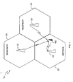
- FIG. 1 illustrates an exemplary mobile communication network indicated generally by the numeral 10.
- Mobile communication network 10 may use Orthogonal Frequency Division Multiplexing (OFDM) as the transmission method for downlink transmissions.
- the geographic area of the mobile communication network 10 is divided into cells 20.
- the cells 20 may be further divided into sectors.
- At least one base station 22 is located in each cell 20 for communicating with a mobile station 100 in the cell 20. If the cell 20 is divided into sectors, the cell 20 may include one base station 22 for all sectors, or separate base stations 22 for each sector in the cell 20.
- each cell 20 comprises a single sector with a single base station 22. The principles described may be easily extended to multi-sector cells 20.
- Transmissions on the downlink from the base station 22 are indicated with solid lines, while uplink transmissions from the mobile station 100 are indicated with dashed lines.
- the mobile station 100 exchanges data and control signals with the base station 22 in the serving cell 20 using uplink and downlink transmissions.
- the mobile stations 100 may also detect downlink transmissions from the base stations 22 in nearby cells 20.
- the serving cell 20 may provide the mobile station 100 with a neighbor list of the nearby cells 20. Alternatively or additionally, the mobile station 100 may detect one or more nearby cells 20. As the mobile station 100 moves away from the serving cell 20 toward a neighbor cell 20, the signal strength from the serving cell 20 will diminish while the signal strength from the neighbor cell 20 will increase.
- the mobile station 100 and/or a controlling entity in the network make handover decisions based on the strength of the serving and neighbor base station signals at the mobile station 100.
- the mobile station 100 measures the signal strength of downlink transmissions from the serving and neighbor base stations 22.
- the mobile station 100 sends the measured signal strengths to the serving base station 22, where the network 10 uses the received signal strength measurements to make handover decisions.
- the mobile station 100 evaluates the signal strength measurements and requests the network 10 to handover the mobile station 100 to a specific neighbor cell 20 based on the evaluation.
- the mobile station 100 may direct the network 10 to handover control to the higher power neighbor cell 20. After handover, the base station 22 in the newly selected cell 20 begins transmitting data and control signals to the mobile station 100.
- the signal strength measurements used for handover decisions should reflect some average signal strength to reduce fast fading effects.
- the mobile station 100 achieves this by determining the strength of a signal in equally spaced snapshot periods of a measurement period.
- One exemplary measurement period is 200 ms long and contains three to four snapshot periods.
- Each snapshot period has a predetermined length generally ranging between 0.5 ms and 5 ms.
- Such a measurement period adequately filters out Doppler rates above 5 - 10 Hz, which corresponds to 3 - 6 km/hr at 2 GHz.
- snapshot periods typically include 2 - 20 OFDM symbols, including reference symbols that may be used to determine a Received Signal Reference symbol Power (RSRP) for a base station 22.
- RSRP Received Signal Reference symbol Power
- the mobile station 100 typically includes one Fast Fourier Transform (FFT) resource operating in an over sampling fashion with respect to the OFDM symbol sampling rate.
- FFT Fast Fourier Transform
- This resource is shared to process data received from the serving base station 22 and to measure the signal strength of signals from the serving and neighbor base stations 22.
- the processing time for an FFT of size N is proportional to the FFT clock rate.
- processing a slot within a signal having a 20 MHz bandwidth typically takes 16 times longer than processing a slot within a signal having a 1.25 MHz bandwidth.
- the widest snapshot period must be selected to obtain the desired measurement accuracy for all possible measurement bandwidths.
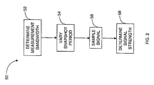
- FIG. 2 shows one exemplary process 50 for making signal strength measurements using variable snapshot periods.
- Mobile station 100 determines the measurement bandwidth for a base station 22 (block 52). The mobile station 100 may process a signal received from the base station 22 to determine the measurement bandwidth. Alternatively, the mobile station 100 may determine the measurement bandwidth based on a bandwidth indicator received from the base station 22. Based on the measurement bandwidth, mobile station 100 selects a snapshot period (block 54).
- the mobile station 100 may use a look-up table that cross-references possible measurement bandwidths with desired snapshot periods. Subsequently, the mobile station 100 samples the signal in the snapshot period (block 56) and determines the strength of a signal received from the base station 22 by processing the samples from the selected snapshot periods within the measurement period (block 58). The mobile station 100 repeats this process for each cell 20 in its neighbor list.
- Mobile station 100 may determine the strength of the signal in a measurement period using any known technique. In one embodiment, the mobile station 100 determines the strength of a signal in two or more snapshot periods within the measurement period. An exemplary measurement period has 3 - 4 snapshot periods. For example, the mobile station 100 may determine the strength of the signal by averaging the signal in a plurality of snapshot periods.
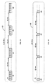
- FIGS 3A and 3B show exemplary measurement periods 60 having different snapshot periods 62 for 1.25 MHz and 20 MHz measurement bandwidths, respectively.
- each measurement period 60 contains four snapshot periods 62 spaced by 60 ms.
- the snapshot period 62 for the 1.25 MHz measurement bandwidth may be set to 5 ms, (10 slots 64).
- the snapshot period 62 for the 20 MHz measurement bandwidth may be set to 1 ms (2 slots 64), as shown in Figure 3B .
- the snapshot period 62 for the 20 MHz measurement bandwidth may be even shorter.
- other factors such as channel delay spread, measurement definition, etc., practically limit the snapshot period 62 to at least 0.5 ms in LTE.
- Mobile station 100 measures the strength of the signal in the snapshot period 62, as discussed above. By making the snapshot periods 62 within each measurement period 60 specific to the measurement bandwidth of the corresponding base station 22, the mobile station 100 tailors the processing time and resources required to determine a signal strength for a specific base station 22 to the base station's measurement bandwidth. This frees up processing resources and more efficiently utilizes power in the mobile station 100.
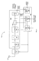
- FIG. 4 shows one exemplary receiver 110 for implementing the above-described signal measurement process 50.
- Receiver 110 may be disposed in any mobile station 100.
- the receiver 110 comprises an antenna 112, a receiver front-end 114, a processing unit 120, and measurement unit 130. It will be appreciated that the present invention is not limited to the specific arrangement of elements shown in Figure 4 .
- the processing unit 120 and/or the measurement unit 130 may comprise one or more microprocessors, microcontrollers, and/or a combination thereof.
- the receiver front-end 114 down-converts a signal received via antenna 112 to a baseband signal.
- Processing unit 120 includes an Analog-to-Digital Converter (ADC) 121, filter 122, buffer 123, switch 124, and FFT unit 125.
- ADC 121 converts the input analog signal to a digital signal, and filter 122 filters the digital signal to the desired signal bandwidth.
- Buffer 123 stores the filtered signal.
- Data signals, such as OFDM symbols, from the base station 22 in the serving cell 20 are fed forward to the FFT unit 125 and processed according to any known technique.
- Measurement unit 130 determines the snapshot period 62 for the serving and neighbor base stations 22. During a period of time corresponding to the snapshot period 62, when the FFT unit 125 is idle, the measurement unit 130 closes switch 124 to provide the signal from the buffer 123 to the FFT unit 125. The measurement unit 130 uses the measurement data output by FFT unit 125 to determine the signal strength measurements for a base station 22.
- measurement unit 130 includes a search unit 132, a switch controller 134, and a measurement calculator 136. Search unit 132 identifies the measurement bandwidth for a base station 22, e.g., by evaluating the received signal or interpreting a received bandwidth identifier.
- the search unit 132 determines the appropriate snapshot period 62 for the base station 22.
- the signal stored in switch controller 134 controls switch 124 to provide the signal stored in buffer 123 to the FFT unit 125 during the determined snapshot periods of the measurement period.
- FFT unit 125 processes the signal in the snapshot periods and provides measurement data to the measurement unit 130.
- Measurement calculator 136 processes the measurement data provided by FFT unit 125 to determine the signal strength measurement for the cell 20.
- the calculated signal strength measurement may be in the form of a Received Signal Reference symbol Power (RSRP), Received Signal Strength Indicator (RSSI), or any combination thereof.
- RSRP Received Signal Reference symbol Power
- RSSI Received Signal Strength Indicator
- measurement unit 130 controls switch 124 in this manner for each of the serving base station 22 and one or more neighbor base stations 22.
- a controller (not shown) in the mobile station 100 makes handover decisions based on the signal strength measurements output by measurement unit 130.
- the mobile station 100 sends the signal strength measurements output by the measurement unit 130 to the serving base station 22.
- the above described method and apparatus tailors the snapshot periods used to obtain signal strength measurements for a particular base station to the measurement bandwidth of the base station. This enables the mobile station 100 to efficiently allocate resources, e.g., power and FFT processing resources. Further, while the FFT unit 125 processes buffered signals as described above, measurement unit 130 may deactivate the receiver 114 and/or ADC 121 to further conserve power resources.
- resources e.g., power and FFT processing resources.
Description
- The present invention relates generally to making signal strength measurements, and more particularly to making signal strength measurements during variable snapshot periods. Handover operations in a wireless network often rely on signal strength measurements collected by the mobile stations in the network. For example, mobile stations may measure the strength of signals received from base stations in a serving cell and one or more neighbor cells. A mobile station may assist with handover operations by reporting the measured signal strengths to the network. Alternatively, a mobile station may direct handover operations by requesting handover based on the measured signal strengths.
- In conventional networks, the mobile station typically samples and measures the strength of the received signal for a fixed period, referred to herein as the snapshot period. The conventional practice may lead to problems. For example, the Long Term Evolution (LTE) of the Third Generation Partnership Project (3GPP), which may use Orthogonal Frequency Division Multiplexing (OFDM) to implement wireless communications between mobile stations and a wireless network, is expected to allow flexible signal bandwidths from 1.25 MHz to 20 MHz by allocating a variable number of subcarriers. Proposed signal bandwidths currently include 1.25, 1.6, 2.5, 5, 10, 15, and 20 MHz. When the snapshot period is fixed, the number of samples or measurements depends on the signal bandwidth and the length of the snapshot period. For narrow signal bandwidths, the snapshot periods should be long enough to allow a sufficient number of samples to be taken to obtain a reliable estimate of the signal strength. Because the number of samples increases with signal bandwidth, the processing speed or processing capacity needs to be high enough to process measurements for wide signal bandwidths. In some cases, this causes the mobile station to process an unnecessarily large amount of data, and therefore, to expend an unnecessarily large amount of current.
- In following document have been identified to form stock of the art
- NOKIA, NOKIA SIEMENS NETWORKS: "R4-071329 RSSI measurement bandwidth",
3GPP TSG-RAN4 MEETING#44, 16 August 2007 (2007-08-16),
Athens, Greece, 20∼24 August 2007 - QUALCOMM EUROPE: "R4.071033 Time and frequency averaging for mobility measurements",
3GPP TSG-RAN WG4 MEETING #43BIS, 21 June 2007 (2007∼06∼21),
Orlando, Florida, 25-29 June 2007 - 3GPP RAN WG1: "LS on LTE measurements supportring mobility", 3GPP TSG-RAN WG1 MEETING#48, 26 February 2007 (2007-02-26),
St.Louis, USA, 12-16 February 2007 - D1 discusses the RSSI measurement bandwidth options that might be considered for intra and inter- frequency operations in LTE. It is possible to measure signal strength on different bandwidths.
- D2 discusses the trade-offs associated with time and frequency averaging for mobility measurements. It is shown that averaging in time and frequency domain are interchangeable i.e. averaging of the measurement metric over BW "x" MHz and time window "y" is roughly equivalent to that over BW M*x and time-window y/M.
- D3 describes different signal quality measurements which can be used in cell search for LTE.
- The present invention provides a method and apparatus for making signal strength measurements in a system that allows base stations to operate with different signal bandwidths. In one exemplary embodiment, a wireless receiver varies a snapshot period used to make signal strength measurements based on the corresponding base station's signal bandwidth. In one embodiment, a wireless receiver includes a measurement unit. The measurement unit determines a measurement bandwidth and varies a snapshot period for making signal strength measurements based on the measurement bandwidth. The measurement unit determines the strength of the received signal in the snapshot period.
-
-
Figure 1 shows one exemplary wireless network. -
Figure 2 shows a flow chart for an exemplary method according to one embodiment of the present invention. -
Figures 3A and 3B show exemplary snap shot periods within a measurement period for different measurement bandwidths. -
Figure 4 shows a block diagram of an exemplary receiver according to one embodiment of the present invention. - The method and apparatus of the present invention makes signal strength measurements in a mobile communication network that allows different base stations to operate with different signal bandwidths. Such signal strength measurements may be used to assist and/or direct handover operations. To facilitate the description of various embodiments, the following first provides a general description of an exemplary mobile communication network.
-
Figure 1 illustrates an exemplary mobile communication network indicated generally by thenumeral 10.Mobile communication network 10 may use Orthogonal Frequency Division Multiplexing (OFDM) as the transmission method for downlink transmissions. The geographic area of themobile communication network 10 is divided intocells 20. Thecells 20 may be further divided into sectors. At least onebase station 22 is located in eachcell 20 for communicating with amobile station 100 in thecell 20. If thecell 20 is divided into sectors, thecell 20 may include onebase station 22 for all sectors, orseparate base stations 22 for each sector in thecell 20. To simplify the explanation of the present invention, it is assumed that eachcell 20 comprises a single sector with asingle base station 22. The principles described may be easily extended tomulti-sector cells 20. - Transmissions on the downlink from the
base station 22 are indicated with solid lines, while uplink transmissions from themobile station 100 are indicated with dashed lines. Themobile station 100 exchanges data and control signals with thebase station 22 in the servingcell 20 using uplink and downlink transmissions. Themobile stations 100 may also detect downlink transmissions from thebase stations 22 innearby cells 20. The servingcell 20 may provide themobile station 100 with a neighbor list of thenearby cells 20. Alternatively or additionally, themobile station 100 may detect one or morenearby cells 20. As themobile station 100 moves away from theserving cell 20 toward aneighbor cell 20, the signal strength from theserving cell 20 will diminish while the signal strength from theneighbor cell 20 will increase. - The
mobile station 100 and/or a controlling entity in the network make handover decisions based on the strength of the serving and neighbor base station signals at themobile station 100. To that end, themobile station 100 measures the signal strength of downlink transmissions from the serving andneighbor base stations 22. For mobile-assisted handover, themobile station 100 sends the measured signal strengths to theserving base station 22, where thenetwork 10 uses the received signal strength measurements to make handover decisions. For mobile-directed handover, themobile station 100 evaluates the signal strength measurements and requests thenetwork 10 to handover themobile station 100 to aspecific neighbor cell 20 based on the evaluation. For example, when the signal strength from aneighbor base station 22 exceeds the signal strength from theserving base station 22 by a predetermined amount, themobile station 100 may direct thenetwork 10 to handover control to the higherpower neighbor cell 20. After handover, thebase station 22 in the newly selectedcell 20 begins transmitting data and control signals to themobile station 100. - The signal strength measurements used for handover decisions should reflect some average signal strength to reduce fast fading effects. Typically, the
mobile station 100 achieves this by determining the strength of a signal in equally spaced snapshot periods of a measurement period. One exemplary measurement period is 200 ms long and contains three to four snapshot periods. Each snapshot period has a predetermined length generally ranging between 0.5 ms and 5 ms. Such a measurement period adequately filters out Doppler rates above 5 - 10 Hz, which corresponds to 3 - 6 km/hr at 2 GHz. In an OFDM system, such snapshot periods typically include 2 - 20 OFDM symbols, including reference symbols that may be used to determine a Received Signal Reference symbol Power (RSRP) for abase station 22. - The
mobile station 100 typically includes one Fast Fourier Transform (FFT) resource operating in an over sampling fashion with respect to the OFDM symbol sampling rate. This resource is shared to process data received from the servingbase station 22 and to measure the signal strength of signals from the serving andneighbor base stations 22. The processing time for an FFT of size N is proportional to the FFT clock rate. Thus, processing a slot within a signal having a 20 MHz bandwidth typically takes 16 times longer than processing a slot within a signal having a 1.25 MHz bandwidth. When a mobile station relies on fixed snapshot periods to determine signal strength measurements fordifferent base stations 22 having different measurement bandwidths, such asbase stations 22 in an LTE network, the widest snapshot period must be selected to obtain the desired measurement accuracy for all possible measurement bandwidths. As a result, conventional mobile stations must allocate the FFT resources required for a 1.25 MHz bandwidth to each signal strength measurement operation, even when the actual measurement bandwidth differs from 1.25 MHz. This may cause various processing and/or power consumption inefficiencies. The present invention addresses this problem by varying the snapshot period based on the measurement bandwidth.Figure 2 shows oneexemplary process 50 for making signal strength measurements using variable snapshot periods.Mobile station 100 determines the measurement bandwidth for a base station 22 (block 52). Themobile station 100 may process a signal received from thebase station 22 to determine the measurement bandwidth. Alternatively, themobile station 100 may determine the measurement bandwidth based on a bandwidth indicator received from thebase station 22. Based on the measurement bandwidth,mobile station 100 selects a snapshot period (block 54). For example, themobile station 100 may use a look-up table that cross-references possible measurement bandwidths with desired snapshot periods. Subsequently, themobile station 100 samples the signal in the snapshot period (block 56) and determines the strength of a signal received from thebase station 22 by processing the samples from the selected snapshot periods within the measurement period (block 58). Themobile station 100 repeats this process for eachcell 20 in its neighbor list. -
Mobile station 100 may determine the strength of the signal in a measurement period using any known technique. In one embodiment, themobile station 100 determines the strength of a signal in two or more snapshot periods within the measurement period. An exemplary measurement period has 3 - 4 snapshot periods. For example, themobile station 100 may determine the strength of the signal by averaging the signal in a plurality of snapshot periods. -
Figures 3A and 3B showexemplary measurement periods 60 havingdifferent snapshot periods 62 for 1.25 MHz and 20 MHz measurement bandwidths, respectively. In the illustrated examples, eachmeasurement period 60 contains foursnapshot periods 62 spaced by 60 ms. As shown inFigure 3A , thesnapshot period 62 for the 1.25 MHz measurement bandwidth may be set to 5 ms, (10 slots 64). Contrastingly, thesnapshot period 62 for the 20 MHz measurement bandwidth may be set to 1 ms (2 slots 64), as shown inFigure 3B . In theory, thesnapshot period 62 for the 20 MHz measurement bandwidth may be even shorter. However, other factors, such as channel delay spread, measurement definition, etc., practically limit thesnapshot period 62 to at least 0.5 ms in LTE.Mobile station 100 measures the strength of the signal in thesnapshot period 62, as discussed above. By making thesnapshot periods 62 within eachmeasurement period 60 specific to the measurement bandwidth of thecorresponding base station 22, themobile station 100 tailors the processing time and resources required to determine a signal strength for aspecific base station 22 to the base station's measurement bandwidth. This frees up processing resources and more efficiently utilizes power in themobile station 100. -
Figure 4 shows oneexemplary receiver 110 for implementing the above-describedsignal measurement process 50.Receiver 110 may be disposed in anymobile station 100. Thereceiver 110 comprises anantenna 112, a receiver front-end 114, aprocessing unit 120, andmeasurement unit 130. It will be appreciated that the present invention is not limited to the specific arrangement of elements shown inFigure 4 . Theprocessing unit 120 and/or themeasurement unit 130 may comprise one or more microprocessors, microcontrollers, and/or a combination thereof. - The receiver front-
end 114 down-converts a signal received viaantenna 112 to a baseband signal.Processing unit 120 includes an Analog-to-Digital Converter (ADC) 121,filter 122,buffer 123,switch 124, andFFT unit 125.ADC 121 converts the input analog signal to a digital signal, and filter 122 filters the digital signal to the desired signal bandwidth. Buffer 123 stores the filtered signal. Data signals, such as OFDM symbols, from thebase station 22 in the servingcell 20 are fed forward to theFFT unit 125 and processed according to any known technique. -
Measurement unit 130 determines thesnapshot period 62 for the serving andneighbor base stations 22. During a period of time corresponding to thesnapshot period 62, when theFFT unit 125 is idle, themeasurement unit 130 closes switch 124 to provide the signal from thebuffer 123 to theFFT unit 125. Themeasurement unit 130 uses the measurement data output byFFT unit 125 to determine the signal strength measurements for abase station 22. In one embodiment,measurement unit 130 includes asearch unit 132, aswitch controller 134, and ameasurement calculator 136.Search unit 132 identifies the measurement bandwidth for abase station 22, e.g., by evaluating the received signal or interpreting a received bandwidth identifier. Based on the identified measurement bandwidth, thesearch unit 132 determines theappropriate snapshot period 62 for thebase station 22. WhenFFT unit 125 indicates it is idle, the signal stored inswitch controller 134 controls switch 124 to provide the signal stored inbuffer 123 to theFFT unit 125 during the determined snapshot periods of the measurement period.FFT unit 125 processes the signal in the snapshot periods and provides measurement data to themeasurement unit 130.Measurement calculator 136 processes the measurement data provided byFFT unit 125 to determine the signal strength measurement for thecell 20. The calculated signal strength measurement may be in the form of a Received Signal Reference symbol Power (RSRP), Received Signal Strength Indicator (RSSI), or any combination thereof. It will be appreciated thatmeasurement unit 130 controls switch 124 in this manner for each of the servingbase station 22 and one or moreneighbor base stations 22. For mobile-directed handover, a controller (not shown) in themobile station 100 makes handover decisions based on the signal strength measurements output bymeasurement unit 130. For mobile-assisted handover, themobile station 100 sends the signal strength measurements output by themeasurement unit 130 to the servingbase station 22. - The above described method and apparatus tailors the snapshot periods used to obtain signal strength measurements for a particular base station to the measurement bandwidth of the base station. This enables the
mobile station 100 to efficiently allocate resources, e.g., power and FFT processing resources. Further, while theFFT unit 125 processes buffered signals as described above,measurement unit 130 may deactivate thereceiver 114 and/orADC 121 to further conserve power resources. - The above describes the invention in terms of an LTE network that uses OFDM signaling. However, it will be appreciated that the present invention applies to any variable signal bandwidth network that requires the mobile station to measure the strength of signals received at the mobile station from the serving base station and one or more neighbor base stations.
- The present invention may, of course, be carried out in other ways than those specifically set forth herein without departing from essential characteristics of the invention. The present embodiments are to be considered in all respects as illustrative and not restrictive, and all changes coming within the meaning and equivalency range of the appended claims are intended to be embraced therein.
Claims (15)
- A method for measuring the strength of received signals comprising:determining a measurement bandwidth (52);varying a snapshot period within a measurement period based on the measurement bandwidth, said snapshot period for determining signal strength measurements (54); anddetermining signal strength measurements of a received signal in the snapshot period (58).
- The method of claim 1 wherein varying the snapshot period comprises:reducing the snapshot period with increasing measurement bandwidth; andincreasing the snapshot period with decreasing measurement bandwidth.
- The method of claim 1 wherein determining the measurement bandwidth comprises:receiving a bandwidth indicator from a network device; anddetermining the measurement bandwidth based on the received bandwidth indicator.
- The method of claim 1 wherein determining signal strength measurements comprises determining the signal strength measurements of the received signal in two or more snapshot periods within the measurement period, wherein the number of snapshot periods within the measurement period does not vary with the measurement bandwidth.
- The method of claim 4 further comprising determining an average signal strength based on the signal strength measurements determined during the measurement period.
- The method of claim 5 wherein the average signal strength is associated with a base station in a serving sector or cell.
- The method of claim 6 wherein the average signal strength is associated with a base station in a neighbor sector or cell.
- A wireless receiver comprising:a receiver (114) to receive a wireless signal; anda measurement unit (130) configured to:determine a measurement bandwidth;vary a snapshot period within a measurement period based on the measurement bandwidth, said snapshot period for determining signal strength measurements; anddetermining signal strength measurements of the received signal in the snapshot period.
- The wireless receiver of claim 8 wherein the measurement unit varies the snapshot period by:reducing the snapshot period with increasing measurement bandwidth; andincreasing the snapshot period with decreasing measurement bandwidth.
- The wireless receiver of claim 8 wherein the measurement unit determines the measurement bandwidth by:receiving a bandwidth indicator from a network device; anddetermining the measurement bandwidth based on the received bandwidth indicator.
- The wireless receiver of claim 8 wherein the wireless signal includes information regarding the measurement bandwidth, and wherein the measurement unit processes the wireless signal to determine the measurement bandwidth.
- The wireless receiver of claim 8 wherein the measurement unit determines the signal strength measurements by processing the received signal in two or more snapshot periods within the measurement period, wherein the number of snapshot periods within the measurement period does not vary with the measurement bandwidth.
- The wireless receiver of claim 12 wherein the measurement unit is further configured to determine an average signal strength based on the signal strength measurements determined during the measurement period.
- The wireless receiver of claim 13 wherein the average signal strength is associated with a serving cell.
- The wireless receiver of claim 13 wherein the average signal strength is associated with a neighboring cell.
Applications Claiming Priority (2)
| Application Number | Priority Date | Filing Date | Title |
|---|---|---|---|
| US11/856,233 US7787845B2 (en) | 2007-09-17 | 2007-09-17 | UE measurement scheduling based on measurement bandwidth |
| PCT/EP2008/061114 WO2009037068A1 (en) | 2007-09-17 | 2008-08-26 | Ue measurement scheduling based on measurement bandwidth |
Publications (2)
| Publication Number | Publication Date |
|---|---|
| EP2191595A1 EP2191595A1 (en) | 2010-06-02 |
| EP2191595B1 true EP2191595B1 (en) | 2012-10-03 |
Family
ID=40042593
Family Applications (1)
| Application Number | Title | Priority Date | Filing Date |
|---|---|---|---|
| EP08787464A Active EP2191595B1 (en) | 2007-09-17 | 2008-08-26 | Ue measurement scheduling based on measurement bandwidth |
Country Status (4)
| Country | Link |
|---|---|
| US (1) | US7787845B2 (en) |
| EP (1) | EP2191595B1 (en) |
| JP (1) | JP5216857B2 (en) |
| WO (1) | WO2009037068A1 (en) |
Families Citing this family (16)
| Publication number | Priority date | Publication date | Assignee | Title |
|---|---|---|---|---|
| ES2655043T3 (en) | 2007-02-05 | 2018-02-16 | Telefonaktiebolaget Lm Ericsson (Publ) | Method and arrangement in a telecommunication system for measurements of neighboring cells |
| JP5185561B2 (en) * | 2007-04-16 | 2013-04-17 | 株式会社エヌ・ティ・ティ・ドコモ | Communication apparatus and communication method |
| GB2455060A (en) * | 2007-10-29 | 2009-06-03 | Nec Corp | Channel measurement in a mobile communications system |
| US8068838B1 (en) * | 2008-08-19 | 2011-11-29 | Clear Wireless Llc | Mobile communication device initiated hand-off based on air interface metrics |
| US8503400B2 (en) * | 2008-09-18 | 2013-08-06 | Sharp Laboratories Of America, Inc. | Systems and methods for closed subscriber group cell reselection |
| US8848688B1 (en) * | 2008-10-03 | 2014-09-30 | Sprint Spectrum L.P. | System and method for using a handoff threshold associated with a slot cycle index to determine whether to perform an access terminal handoff |
| JP5411351B2 (en) * | 2009-04-27 | 2014-02-12 | テレフオンアクチーボラゲット エル エム エリクソン(パブル) | Method and apparatus in a wireless communication system |
| US8780688B2 (en) * | 2009-04-27 | 2014-07-15 | Telefonaktiebolaget Lm Ericsson (Publ) | Methods and apparatus in a wireless communication system |
| KR101313271B1 (en) * | 2009-12-18 | 2013-09-30 | 한국전자통신연구원 | Method and apparatus for measuring neighbor cell |
| US8731083B2 (en) * | 2010-02-16 | 2014-05-20 | Nec Corporation | Receiver and signal received power estimation method |
| JP5507400B2 (en) * | 2010-09-29 | 2014-05-28 | 株式会社Nttドコモ | Mobile station apparatus and peripheral cell search processing control method |
| US8761139B2 (en) * | 2010-12-23 | 2014-06-24 | Electronics And Telecommunications Research Institute | Apparatus and method for supporting access in communication system |
| US20140018025A1 (en) * | 2011-03-30 | 2014-01-16 | Ntt Docomo, Inc. | Receiving device, receiving method, and computer program |
| JP5451675B2 (en) | 2011-04-04 | 2014-03-26 | 株式会社Nttドコモ | Mobile device and method |
| US9462529B2 (en) * | 2011-06-21 | 2016-10-04 | Telefonaktiebolaget Lm Ericsson (Publ) | Method and apparatus for accounting of cell related data |
| US8934906B2 (en) | 2012-04-02 | 2015-01-13 | Industrial Technology Research Institute | Method for wireless service handover and base station and relay station using the same |
Family Cites Families (10)
| Publication number | Priority date | Publication date | Assignee | Title |
|---|---|---|---|---|
| US5128959A (en) | 1991-02-22 | 1992-07-07 | Motorola, Inc. | Variable bandwidth CDMA radio system |
| US6205334B1 (en) | 1998-11-24 | 2001-03-20 | Ericsson Inc. | Accelerated scanning of cellular channels by cellular radiotelephones |
| JP4453168B2 (en) | 2000-06-23 | 2010-04-21 | 日本電気株式会社 | Mobile communication control method, cellular system, mobile station, base station, and base station controller |
| US20030157934A1 (en) | 2002-02-01 | 2003-08-21 | Qilian Liang | Method, system, device and computer program product for bandwidth utilization and signal strength-based handover initiation in a wireless communications network |
| US7292656B2 (en) * | 2002-04-22 | 2007-11-06 | Cognio, Inc. | Signal pulse detection scheme for use in real-time spectrum analysis |
| EP1758259A1 (en) * | 2002-07-30 | 2007-02-28 | Interdigital Technology Corporation | Power measurement of received CDMA signals using soft threshold preprocessing after correlation |
| US7801038B2 (en) * | 2003-07-14 | 2010-09-21 | Siemens Corporation | Method and apparatus for providing a delay guarantee for a wireless network |
| WO2006064391A1 (en) | 2004-12-13 | 2006-06-22 | Koninklijke Philips Electronics N.V. | Method and apparatus for use in handover measurement process |
| US7460869B2 (en) | 2005-03-14 | 2008-12-02 | Nokia Corporation | Adaptive handover measurement interval |
| US8320359B2 (en) | 2005-10-11 | 2012-11-27 | Telefonaktiebolaget L M Ericsson (Publ) | Synchronization channel scheme for super 3G |
-
2007
- 2007-09-17 US US11/856,233 patent/US7787845B2/en active Active
-
2008
- 2008-08-26 EP EP08787464A patent/EP2191595B1/en active Active
- 2008-08-26 JP JP2010524444A patent/JP5216857B2/en active Active
- 2008-08-26 WO PCT/EP2008/061114 patent/WO2009037068A1/en active Application Filing
Also Published As
| Publication number | Publication date |
|---|---|
| WO2009037068A1 (en) | 2009-03-26 |
| EP2191595A1 (en) | 2010-06-02 |
| JP5216857B2 (en) | 2013-06-19 |
| US20090075647A1 (en) | 2009-03-19 |
| US7787845B2 (en) | 2010-08-31 |
| JP2010539766A (en) | 2010-12-16 |
Similar Documents
| Publication | Publication Date | Title |
|---|---|---|
| EP2191595B1 (en) | Ue measurement scheduling based on measurement bandwidth | |
| EP3108686B1 (en) | Wlan throughput prediction | |
| CN101690359B (en) | Handover related measurement reporting for E-UTRAN | |
| JP5079007B2 (en) | Wireless communication system, scheduling method, base station apparatus, and terminal apparatus | |
| CN102160414B (en) | Base station device, mobile station device, mobile communication system, and communication method | |
| US20170034729A1 (en) | Enabling Reporting of Non-Real-Time MDT Measurements | |
| KR101761964B1 (en) | Reporting of non-real-time mdt measurements | |
| US20110201324A1 (en) | Reporting of Non-Real-Time MDT Measurements | |
| CN104919845A (en) | Method and apparatus for reporting performance of terminal in mobile communication system | |
| JP2009534873A (en) | Method and apparatus for controlling local scheduling and distributed scheduling | |
| KR20100111346A (en) | Apparatus and method for supporting peer to peer communication in broadband wireless communication system | |
| EP3412071B1 (en) | Cell selection and cell reselection in a wireless communication network | |
| KR101513830B1 (en) | Method for coordinating at least one first transmission from a single-point transmitter to a single-point receiver and at least one second transmission from a multipoint transmitter or to a multipoint receiver in a radio communication system, network node and mobile station thereof | |
| CN113039849A (en) | Multiple uplink carriers in a cell deployed in unlicensed spectrum | |
| WO2007046734A1 (en) | Apparatus and method for measurement reporting in a cellular telecommunications system | |
| WO2007098498A1 (en) | Delayed response to an access probe | |
| EP2141946A1 (en) | Base station device, frequency allocation method, and mobile communication system using the same | |
| CN106856612B (en) | Multi-point cooperative communication method and base station | |
| EP2466776A1 (en) | Method for reporting channel quality information and system thereof | |
| CN112105031B (en) | Measurement method, terminal and network side equipment | |
| CN113891406B (en) | Cell switching method and device in multi-frequency network | |
| EP3264640A1 (en) | Link adaptation method in wireless communication system employing inter-cell interference randomization technique | |
| JP2017028464A (en) | base station |
Legal Events
| Date | Code | Title | Description |
|---|---|---|---|
| PUAI | Public reference made under article 153(3) epc to a published international application that has entered the european phase |
Free format text: ORIGINAL CODE: 0009012 |
|
| 17P | Request for examination filed |
Effective date: 20100329 |
|
| AK | Designated contracting states |
Kind code of ref document: A1 Designated state(s): AT BE BG CH CY CZ DE DK EE ES FI FR GB GR HR HU IE IS IT LI LT LU LV MC MT NL NO PL PT RO SE SI SK TR |
|
| AX | Request for extension of the european patent |
Extension state: AL BA MK RS |
|
| DAX | Request for extension of the european patent (deleted) | ||
| 17Q | First examination report despatched |
Effective date: 20110124 |
|
| GRAP | Despatch of communication of intention to grant a patent |
Free format text: ORIGINAL CODE: EPIDOSNIGR1 |
|
| GRAS | Grant fee paid |
Free format text: ORIGINAL CODE: EPIDOSNIGR3 |
|
| GRAA | (expected) grant |
Free format text: ORIGINAL CODE: 0009210 |
|
| AK | Designated contracting states |
Kind code of ref document: B1 Designated state(s): AT BE BG CH CY CZ DE DK EE ES FI FR GB GR HR HU IE IS IT LI LT LU LV MC MT NL NO PL PT RO SE SI SK TR |
|
| REG | Reference to a national code |
Ref country code: GB Ref legal event code: FG4D |
|
| REG | Reference to a national code |
Ref country code: AT Ref legal event code: REF Ref document number: 578399 Country of ref document: AT Kind code of ref document: T Effective date: 20121015 Ref country code: CH Ref legal event code: EP |
|
| REG | Reference to a national code |
Ref country code: IE Ref legal event code: FG4D |
|
| REG | Reference to a national code |
Ref country code: DE Ref legal event code: R096 Ref document number: 602008019170 Country of ref document: DE Effective date: 20121129 |
|
| REG | Reference to a national code |
Ref country code: AT Ref legal event code: MK05 Ref document number: 578399 Country of ref document: AT Kind code of ref document: T Effective date: 20121003 |
|
| PG25 | Lapsed in a contracting state [announced via postgrant information from national office to epo] |
Ref country code: SI Free format text: LAPSE BECAUSE OF FAILURE TO SUBMIT A TRANSLATION OF THE DESCRIPTION OR TO PAY THE FEE WITHIN THE PRESCRIBED TIME-LIMIT Effective date: 20121003 |
|
| REG | Reference to a national code |
Ref country code: GR Ref legal event code: EP Ref document number: 20120402718 Country of ref document: GR Effective date: 20130122 |
|
| REG | Reference to a national code |
Ref country code: NL Ref legal event code: VDEP Effective date: 20121003 |
|
| REG | Reference to a national code |
Ref country code: LT Ref legal event code: MG4D |
|
| PG25 | Lapsed in a contracting state [announced via postgrant information from national office to epo] |
Ref country code: SE Free format text: LAPSE BECAUSE OF FAILURE TO SUBMIT A TRANSLATION OF THE DESCRIPTION OR TO PAY THE FEE WITHIN THE PRESCRIBED TIME-LIMIT Effective date: 20121003 Ref country code: NO Free format text: LAPSE BECAUSE OF FAILURE TO SUBMIT A TRANSLATION OF THE DESCRIPTION OR TO PAY THE FEE WITHIN THE PRESCRIBED TIME-LIMIT Effective date: 20130103 Ref country code: LT Free format text: LAPSE BECAUSE OF FAILURE TO SUBMIT A TRANSLATION OF THE DESCRIPTION OR TO PAY THE FEE WITHIN THE PRESCRIBED TIME-LIMIT Effective date: 20121003 Ref country code: ES Free format text: LAPSE BECAUSE OF FAILURE TO SUBMIT A TRANSLATION OF THE DESCRIPTION OR TO PAY THE FEE WITHIN THE PRESCRIBED TIME-LIMIT Effective date: 20130114 Ref country code: NL Free format text: LAPSE BECAUSE OF FAILURE TO SUBMIT A TRANSLATION OF THE DESCRIPTION OR TO PAY THE FEE WITHIN THE PRESCRIBED TIME-LIMIT Effective date: 20121003 Ref country code: IS Free format text: LAPSE BECAUSE OF FAILURE TO SUBMIT A TRANSLATION OF THE DESCRIPTION OR TO PAY THE FEE WITHIN THE PRESCRIBED TIME-LIMIT Effective date: 20130203 Ref country code: HR Free format text: LAPSE BECAUSE OF FAILURE TO SUBMIT A TRANSLATION OF THE DESCRIPTION OR TO PAY THE FEE WITHIN THE PRESCRIBED TIME-LIMIT Effective date: 20121003 Ref country code: FI Free format text: LAPSE BECAUSE OF FAILURE TO SUBMIT A TRANSLATION OF THE DESCRIPTION OR TO PAY THE FEE WITHIN THE PRESCRIBED TIME-LIMIT Effective date: 20121003 |
|
| PG25 | Lapsed in a contracting state [announced via postgrant information from national office to epo] |
Ref country code: LV Free format text: LAPSE BECAUSE OF FAILURE TO SUBMIT A TRANSLATION OF THE DESCRIPTION OR TO PAY THE FEE WITHIN THE PRESCRIBED TIME-LIMIT Effective date: 20121003 Ref country code: PL Free format text: LAPSE BECAUSE OF FAILURE TO SUBMIT A TRANSLATION OF THE DESCRIPTION OR TO PAY THE FEE WITHIN THE PRESCRIBED TIME-LIMIT Effective date: 20121003 Ref country code: PT Free format text: LAPSE BECAUSE OF FAILURE TO SUBMIT A TRANSLATION OF THE DESCRIPTION OR TO PAY THE FEE WITHIN THE PRESCRIBED TIME-LIMIT Effective date: 20130204 |
|
| PG25 | Lapsed in a contracting state [announced via postgrant information from national office to epo] |
Ref country code: AT Free format text: LAPSE BECAUSE OF FAILURE TO SUBMIT A TRANSLATION OF THE DESCRIPTION OR TO PAY THE FEE WITHIN THE PRESCRIBED TIME-LIMIT Effective date: 20121003 |
|
| PG25 | Lapsed in a contracting state [announced via postgrant information from national office to epo] |
Ref country code: BG Free format text: LAPSE BECAUSE OF FAILURE TO SUBMIT A TRANSLATION OF THE DESCRIPTION OR TO PAY THE FEE WITHIN THE PRESCRIBED TIME-LIMIT Effective date: 20130103 Ref country code: SK Free format text: LAPSE BECAUSE OF FAILURE TO SUBMIT A TRANSLATION OF THE DESCRIPTION OR TO PAY THE FEE WITHIN THE PRESCRIBED TIME-LIMIT Effective date: 20121003 Ref country code: EE Free format text: LAPSE BECAUSE OF FAILURE TO SUBMIT A TRANSLATION OF THE DESCRIPTION OR TO PAY THE FEE WITHIN THE PRESCRIBED TIME-LIMIT Effective date: 20121003 Ref country code: CZ Free format text: LAPSE BECAUSE OF FAILURE TO SUBMIT A TRANSLATION OF THE DESCRIPTION OR TO PAY THE FEE WITHIN THE PRESCRIBED TIME-LIMIT Effective date: 20121003 Ref country code: DK Free format text: LAPSE BECAUSE OF FAILURE TO SUBMIT A TRANSLATION OF THE DESCRIPTION OR TO PAY THE FEE WITHIN THE PRESCRIBED TIME-LIMIT Effective date: 20121003 |
|
| PLBE | No opposition filed within time limit |
Free format text: ORIGINAL CODE: 0009261 |
|
| STAA | Information on the status of an ep patent application or granted ep patent |
Free format text: STATUS: NO OPPOSITION FILED WITHIN TIME LIMIT |
|
| PG25 | Lapsed in a contracting state [announced via postgrant information from national office to epo] |
Ref country code: RO Free format text: LAPSE BECAUSE OF FAILURE TO SUBMIT A TRANSLATION OF THE DESCRIPTION OR TO PAY THE FEE WITHIN THE PRESCRIBED TIME-LIMIT Effective date: 20121003 |
|
| 26N | No opposition filed |
Effective date: 20130704 |
|
| REG | Reference to a national code |
Ref country code: DE Ref legal event code: R097 Ref document number: 602008019170 Country of ref document: DE Effective date: 20130704 |
|
| PG25 | Lapsed in a contracting state [announced via postgrant information from national office to epo] |
Ref country code: CY Free format text: LAPSE BECAUSE OF FAILURE TO SUBMIT A TRANSLATION OF THE DESCRIPTION OR TO PAY THE FEE WITHIN THE PRESCRIBED TIME-LIMIT Effective date: 20121003 |
|
| REG | Reference to a national code |
Ref country code: CH Ref legal event code: PL |
|
| PG25 | Lapsed in a contracting state [announced via postgrant information from national office to epo] |
Ref country code: CH Free format text: LAPSE BECAUSE OF NON-PAYMENT OF DUE FEES Effective date: 20130831 Ref country code: LI Free format text: LAPSE BECAUSE OF NON-PAYMENT OF DUE FEES Effective date: 20130831 Ref country code: MC Free format text: LAPSE BECAUSE OF FAILURE TO SUBMIT A TRANSLATION OF THE DESCRIPTION OR TO PAY THE FEE WITHIN THE PRESCRIBED TIME-LIMIT Effective date: 20121003 |
|
| REG | Reference to a national code |
Ref country code: IE Ref legal event code: MM4A |
|
| PG25 | Lapsed in a contracting state [announced via postgrant information from national office to epo] |
Ref country code: IE Free format text: LAPSE BECAUSE OF NON-PAYMENT OF DUE FEES Effective date: 20130826 |
|
| PG25 | Lapsed in a contracting state [announced via postgrant information from national office to epo] |
Ref country code: TR Free format text: LAPSE BECAUSE OF FAILURE TO SUBMIT A TRANSLATION OF THE DESCRIPTION OR TO PAY THE FEE WITHIN THE PRESCRIBED TIME-LIMIT Effective date: 20121003 Ref country code: MT Free format text: LAPSE BECAUSE OF FAILURE TO SUBMIT A TRANSLATION OF THE DESCRIPTION OR TO PAY THE FEE WITHIN THE PRESCRIBED TIME-LIMIT Effective date: 20121003 |
|
| PG25 | Lapsed in a contracting state [announced via postgrant information from national office to epo] |
Ref country code: HU Free format text: LAPSE BECAUSE OF FAILURE TO SUBMIT A TRANSLATION OF THE DESCRIPTION OR TO PAY THE FEE WITHIN THE PRESCRIBED TIME-LIMIT; INVALID AB INITIO Effective date: 20080826 Ref country code: LU Free format text: LAPSE BECAUSE OF NON-PAYMENT OF DUE FEES Effective date: 20130826 |
|
| REG | Reference to a national code |
Ref country code: FR Ref legal event code: PLFP Year of fee payment: 9 |
|
| REG | Reference to a national code |
Ref country code: FR Ref legal event code: PLFP Year of fee payment: 10 |
|
| REG | Reference to a national code |
Ref country code: FR Ref legal event code: PLFP Year of fee payment: 11 |
|
| PGFP | Annual fee paid to national office [announced via postgrant information from national office to epo] |
Ref country code: GR Payment date: 20210827 Year of fee payment: 14 |
|
| PGFP | Annual fee paid to national office [announced via postgrant information from national office to epo] |
Ref country code: GB Payment date: 20220829 Year of fee payment: 15 Ref country code: DE Payment date: 20220629 Year of fee payment: 15 |
|
| PGFP | Annual fee paid to national office [announced via postgrant information from national office to epo] |
Ref country code: FR Payment date: 20220825 Year of fee payment: 15 Ref country code: BE Payment date: 20220829 Year of fee payment: 15 |
|
| PG25 | Lapsed in a contracting state [announced via postgrant information from national office to epo] |
Ref country code: GR Free format text: LAPSE BECAUSE OF NON-PAYMENT OF DUE FEES Effective date: 20230306 |
|
| P01 | Opt-out of the competence of the unified patent court (upc) registered |
Effective date: 20230523 |
|
| PGFP | Annual fee paid to national office [announced via postgrant information from national office to epo] |
Ref country code: IT Payment date: 20230822 Year of fee payment: 16 |
|
| REG | Reference to a national code |
Ref country code: DE Ref legal event code: R119 Ref document number: 602008019170 Country of ref document: DE |