EP2191176B1 - Composite valve - Google Patents
Composite valve Download PDFInfo
- Publication number
- EP2191176B1 EP2191176B1 EP08760651.3A EP08760651A EP2191176B1 EP 2191176 B1 EP2191176 B1 EP 2191176B1 EP 08760651 A EP08760651 A EP 08760651A EP 2191176 B1 EP2191176 B1 EP 2191176B1
- Authority
- EP
- European Patent Office
- Prior art keywords
- valve
- disk
- accordance
- composite
- seal
- Prior art date
- Legal status (The legal status is an assumption and is not a legal conclusion. Google has not performed a legal analysis and makes no representation as to the accuracy of the status listed.)
- Active
Links
Images


Classifications
-
- F—MECHANICAL ENGINEERING; LIGHTING; HEATING; WEAPONS; BLASTING
- F16—ENGINEERING ELEMENTS AND UNITS; GENERAL MEASURES FOR PRODUCING AND MAINTAINING EFFECTIVE FUNCTIONING OF MACHINES OR INSTALLATIONS; THERMAL INSULATION IN GENERAL
- F16K—VALVES; TAPS; COCKS; ACTUATING-FLOATS; DEVICES FOR VENTING OR AERATING
- F16K1/00—Lift valves or globe valves, i.e. cut-off apparatus with closure members having at least a component of their opening and closing motion perpendicular to the closing faces
- F16K1/16—Lift valves or globe valves, i.e. cut-off apparatus with closure members having at least a component of their opening and closing motion perpendicular to the closing faces with pivoted closure-members
- F16K1/18—Lift valves or globe valves, i.e. cut-off apparatus with closure members having at least a component of their opening and closing motion perpendicular to the closing faces with pivoted closure-members with pivoted discs or flaps
- F16K1/22—Lift valves or globe valves, i.e. cut-off apparatus with closure members having at least a component of their opening and closing motion perpendicular to the closing faces with pivoted closure-members with pivoted discs or flaps with axis of rotation crossing the valve member, e.g. butterfly valves
- F16K1/226—Shaping or arrangements of the sealing
- F16K1/2263—Shaping or arrangements of the sealing the sealing being arranged on the valve seat
-
- F—MECHANICAL ENGINEERING; LIGHTING; HEATING; WEAPONS; BLASTING
- F16—ENGINEERING ELEMENTS AND UNITS; GENERAL MEASURES FOR PRODUCING AND MAINTAINING EFFECTIVE FUNCTIONING OF MACHINES OR INSTALLATIONS; THERMAL INSULATION IN GENERAL
- F16K—VALVES; TAPS; COCKS; ACTUATING-FLOATS; DEVICES FOR VENTING OR AERATING
- F16K27/00—Construction of housing; Use of materials therefor
- F16K27/02—Construction of housing; Use of materials therefor of lift valves
- F16K27/0209—Check valves or pivoted valves
- F16K27/0218—Butterfly valves
Definitions
- the present invention relates generally to valve compare thereto for instance US-A-2 912 218 or EP-A-114 417 . More particularly, the invention relates to a butterfly valve utilizing a composite two-piece housing.
- the valve provides a low cost, high strength, light weight alternative to metal body and plastic valves adaptable for corrosive and non-corrosive environments.
- Process valves are used in various types of applications to prevent and/or allow the flow of media through a pipeline. These valves are mounted within a pipeline and clamped or otherwise held in position between a pair of pipe flanges.
- Conventional valves are usually made of a metal body. The trim of the valve (disc and seat) depending on temperature and pressure requirements for a particular type of application.
- metal valves provide for long and reliable stroke life, they are relatively heavy which may require additional physical support within a pipeline structure. The relative high weight can be considered as a disadvantage for installation locations which are difficult to reach, as well as in applications in road and cargo containers.
- Metal body valves also have a limited external corrosion resistance when installed in maritime environments.
- plastic valves have been employed in low temperature and low pressure environments to provide a light weight, low cost alternative to metal valves.
- Typical plastic valve materials include, for example, PVC, PVC-U, PP, ABS, etc.
- plastic valves have a restricted pressure rating at elevated temperatures.
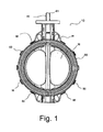
- FIG. 1 illustrates an exemplary embodiment of a composite valve 10 in a closed position mounted along a process pipeline that when opened, provides an inlet and outlet flow passage within the pipeline. In its closed position, valve 10 prevents process media from flowing downstream or upstream within the pipeline.
- Valve 10 includes a valve disk 30 disposed within valve housing or body 20.
- a disk stem 40 is disposed within a central axis of disk 30 and extends a distance above and below housing 20.
- Disk stem 40 is configured, at its top end 41, to receive a mechanism (actuator, handle, etc.) to rotate disk 30 to open and closed positions.
- the diameter of disk 30 may be, for example, 50 -300mm with other sizes configured for particular applications.
- Disk 30 may have an inner core of short fiber composite material and an outer layer of high resistant long fiber composite material to provide strength.
- Housing 20 inciudes a plurality of clamps 50 spaced around the perimeter of valve 10 to provide a fastening mechanism for the housing as described in detail below.
- O-ring 55 is disposed within a cavity extending around the outside of housing 20 to create a seal between valve 10 and the process pipeline in which valve 10 is mounted.
- the composite material utilized for housing 20 includes up to 60% of inorganic fillers which obstruct water absorption and provide dimensional stability.
- the present embodiment of valve 10 may be used in pressures of up to 10 bar and in a temperature range of -40°C to 120°C.
- valve 10 may be employed in corrosive environments in high line velocities and vacuum applications.
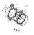
- Fig. 2 is a prospective partitioned view of valve 10 illustrating housing 20 which is defined by first valve body half 210 and second valve body half 220 and disk assembly 201.
- First body half 210 is connected to second body half 220 via clamps 50.
- Disk assembly 201 includes valve disk 30, valve stem 40 and circular seat 250.
- First body half 210 includes a top portion 211, bottom portion 212 and circular portion 213.
- Second body half 220 includes top portion 221, bottom portion 222 and circular portion 223. Top portion 211 and bottom portion 212 are adapted to receive an end portion of disk stem 40 and circular portion 213 is adapted to receive a portion of disk 30.
- top portion 221 and bottom portion 222 are adapted to receive an end portion of disk stem 40 and circular portion 213 is adapted to receive a portion of disk 30.
- top portions 211 and 221 of body halves 210 and 220 respectively, receives end portion 31 of valve stem 40.
- Bottom portions 212 and 222 of body halves 210 and 220 respectively receive lower portion 43 (shown in FIG. 3 ) of valve stem 40.
- Each body half 210 and 220 is molded with a plurality of cavities 231 interspersed within each body half to provide rigidity and strength to housing 20.
- Disk assembly 201 is disposed between first body half 210 and second body half 220.
- Seat 250 surrounds the circumference of disk 30 to create a tight seal there between.
- the outer circumference of disk 30 creates a seal with seat 250 when valve 10 is in a closed position sufficient to prevent process flow through valve 10.
- the seal between seat 250 and disk 30 is broken as disk 30 is rotated about valve stem 40 sufficient to allow process flow through valve 10.
- Disk 30 is made from an extended grade composite material with corrosion resistance and mechanical properties.
- Seat 250 may be an elastomer such as ethylene propylene diene monomer (EPDM) and forms a primary sealing and secondary body split sealing as described below.
- Disk 30 is fixedly attached to and rotates around a substantially central axis about valve stem 40.
- Disk 30 may be manufactured using an injection molding process and valve stem 40 is preferably stainless steel to withstand various forces during valve operation.
- circular portion 213 receives O-ring 55 to accommodate flange sealing with an attached pipeline.
- circular portion 223 also receives O-ring 55 to accommodate flange sealing with an attached pipeline.
- the two O-rings 55 are similarly configured and allow for a wide range of flange connections including slip-on and burdel flanges with no additional flange sealing required.
- Fig. 3 is a side partitioned view illustrating the components that comprise clamp 50 used to attach first body half 210 to second body half 220 as shown in Fig. 1 .
- clamps 50 are spaced around the perimeter of valve housing 20. Depending on the size of the valve, the number and distance between clamps 50 may vary.
- Each clamp 50 is defined by at least two parts: namely first clamp half 50a and second clamp half 50b.
- Each clamp part includes an extension arm 51a or 51b having a curled end 52a or 52b that either bends toward disk 30 (curled end 52a) or bends outward away from disk 30 (curled end 52b).
- Each clamp half 50a and 50b are joined such that the respective curled ends 52a and 52b engage clamp ridges 54a and 54b, respectively.
- curled end 52a of extension arm 51a of clamp half 50a engages clamp ridge 54b of second clamp half 50b.
- curled end 52b of extension arm 51b of clamp half 50b engages clamp ridge 54a of clamp half 50a.
- the direction of the curled clamp ends 52a and 52b alternate for each clamp 50 around the perimeter of valve body 20.
- extension arm 51a has a curled end 52a which bends toward disk 30.
- Adjacent clamp halves 50c includes extension arm 51c having curled end 52c that bends away from disk 30 as compared to clamp half 50a.
- Clamp half 50b includes extension arm 51b having a curled end 52b which bends outward away from disk 30.
- adjacent clamp half 50d includes extension arm 51d having curled end 52d which bends inward toward disk 30. In this manner, the adjacent clamps around the perimeter of valve body halves 210 and 220 have alternating curled extension arms to provide a clamping mechanism that retains valve disk assembly 201 within valve housing 20.
- FIG 4A is a sectional cut-away view of the valve housing 20 comprised of first body half 210, second body half 220 and seal 250 integrally positioned therein to create a seal with disk 30.
- Seal 250 has an internal valve surface 430 that engages disk 30 when valve 10 is in a closed position.
- Seat 250 is defined by a primary split seal portion 410 and a secondary split seal portion 420.
- O-ring 55 is shown as positioned within groove 440 of circular housing portion 223 to provide a flange sealing connection when valve 10 is attached to a pipeline.
- Cavity 231 is formed by respective molded cavities in each of body halves 210 and 220.
- FIG. 4B is a cross sectional top view of valve housing 20 to better illustrate the configuration of primary split seal portion 410 and secondary split seal portion 420.
- primary split seal portion 410 has a generally rectangular shape with cut out portions 411. These cut away portions 411 provide a retaining edge that engages the respective valve body halves 210 and 220 and secure seal 250 in position.
- Secondary split seal portion 420 has a substantially triangular shape and defines ridged portions 412. Similar to cut-away portions 411 of primary split seal 410, ridged portions 412 provide a retaining edge for seal 250 within housing valve housing 20.
- seal 250 acts like a bonded seat. Accordingly, a composite valve having a two-piece housing construction provides a resilient sealing configuration and provides a low cost, high strength, light weight valve for use in corrosive and non-corrosive environments.
Landscapes
- Engineering & Computer Science (AREA)
- General Engineering & Computer Science (AREA)
- Mechanical Engineering (AREA)
- Lift Valve (AREA)
- Valve Housings (AREA)
Description
- The present invention relates generally to valve compare thereto for instance
US-A-2 912 218 orEP-A-114 417 - Process valves are used in various types of applications to prevent and/or allow the flow of media through a pipeline. These valves are mounted within a pipeline and clamped or otherwise held in position between a pair of pipe flanges. Conventional valves are usually made of a metal body. The trim of the valve (disc and seat) depending on temperature and pressure requirements for a particular type of application. While metal valves provide for long and reliable stroke life, they are relatively heavy which may require additional physical support within a pipeline structure. The relative high weight can be considered as a disadvantage for installation locations which are difficult to reach, as well as in applications in road and cargo containers. Metal body valves also have a limited external corrosion resistance when installed in maritime environments. Alternatively, plastic valves have been employed in low temperature and low pressure environments to provide a light weight, low cost alternative to metal valves. Typical plastic valve materials include, for example, PVC, PVC-U, PP, ABS, etc. However, plastic valves have a restricted pressure rating at elevated temperatures.
- Composite valves have been introduced to provide an alternative to both metal and plastic valves. However, thermal expansion properties of various types of composites sometimes compromises the sealing properties associated with these valves. In addition, the positioning of the valve seals within the valve body has not been configured to withstand the forces associated with opening and closing these valves within a process pipeline.
- The above-referenced drawbacks and others are overcome by the present invention described herein with reference to the detailed description, drawings and appended claims.
- According to the present invention there is provided a composite butterfly valve as defined in claim 1.
-
FIG 1 illustrates an exemplary embodiment of a composite valve in a closed position in accordance with an embodiment of the present invention. -
FIG 2 is a prospective partitioned view of a composite valve in accordance with an embodiment of the present invention. -
FIG 3 is a side partitioned view of a composite valve in accordance with an embodiment of the present invention. -
FIG 4A is a sectional cut-away view of the valve seal in accordance with an embodiment of the present invention. -
FIG. 4B is a cross sectional top view of valve housing and valve seal in accordance with an embodiment of the present invention. - The present invention will now be described more fully hereinafter with reference to the accompanying drawings, in which preferred embodiments of the invention are shown. This invention, however, may be embodied in many different forms and should not be construed as limited to the embodiments set forth herein. Rather, these embodiments are provided so that this disclosure will be thorough and complete, and will fully convey the scope of the invention to those skilled in the art. In the drawings, like numbers refer to like elements throughout.
-
Figure 1 illustrates an exemplary embodiment of acomposite valve 10 in a closed position mounted along a process pipeline that when opened, provides an inlet and outlet flow passage within the pipeline. In its closed position,valve 10 prevents process media from flowing downstream or upstream within the pipeline. Valve 10 includes avalve disk 30 disposed within valve housing orbody 20. Adisk stem 40 is disposed within a central axis ofdisk 30 and extends a distance above and belowhousing 20.Disk stem 40 is configured, at itstop end 41, to receive a mechanism (actuator, handle, etc.) to rotatedisk 30 to open and closed positions. The diameter ofdisk 30 may be, for example, 50 -300mm with other sizes configured for particular applications.Disk 30 may have an inner core of short fiber composite material and an outer layer of high resistant long fiber composite material to provide strength. -
Housing 20 inciudes a plurality ofclamps 50 spaced around the perimeter ofvalve 10 to provide a fastening mechanism for the housing as described in detail below. O-ring 55 is disposed within a cavity extending around the outside ofhousing 20 to create a seal betweenvalve 10 and the process pipeline in whichvalve 10 is mounted. The composite material utilized forhousing 20 includes up to 60% of inorganic fillers which obstruct water absorption and provide dimensional stability. The present embodiment ofvalve 10 may be used in pressures of up to 10 bar and in a temperature range of -40°C to 120°C. In addition,valve 10 may be employed in corrosive environments in high line velocities and vacuum applications. -
Fig. 2 is a prospective partitioned view ofvalve 10 illustratinghousing 20 which is defined by firstvalve body half 210 and secondvalve body half 220 anddisk assembly 201.First body half 210 is connected tosecond body half 220 viaclamps 50.Disk assembly 201 includesvalve disk 30,valve stem 40 andcircular seat 250.First body half 210 includes atop portion 211,bottom portion 212 andcircular portion 213.Second body half 220 includestop portion 221,bottom portion 222 andcircular portion 223.Top portion 211 andbottom portion 212 are adapted to receive an end portion ofdisk stem 40 andcircular portion 213 is adapted to receive a portion ofdisk 30. Similarly,top portion 221 andbottom portion 222 are adapted to receive an end portion ofdisk stem 40 andcircular portion 213 is adapted to receive a portion ofdisk 30. In particular,top portions body halves valve stem 40.Bottom portions body halves FIG. 3 ) ofvalve stem 40. Eachbody half cavities 231 interspersed within each body half to provide rigidity and strength to housing 20. -
Disk assembly 201 is disposed betweenfirst body half 210 andsecond body half 220.Seat 250 surrounds the circumference ofdisk 30 to create a tight seal there between. In particular, the outer circumference ofdisk 30 creates a seal withseat 250 whenvalve 10 is in a closed position sufficient to prevent process flow throughvalve 10. In an open position, the seal betweenseat 250 anddisk 30 is broken asdisk 30 is rotated aboutvalve stem 40 sufficient to allow process flow throughvalve 10.Disk 30 is made from an extended grade composite material with corrosion resistance and mechanical properties. Seat 250 may be an elastomer such as ethylene propylene diene monomer (EPDM) and forms a primary sealing and secondary body split sealing as described below.Disk 30 is fixedly attached to and rotates around a substantially central axis aboutvalve stem 40.Disk 30 may be manufactured using an injection molding process andvalve stem 40 is preferably stainless steel to withstand various forces during valve operation. - As noted above, the outer surface of
circular portion 213 receives O-ring 55 to accommodate flange sealing with an attached pipeline. Similarly,circular portion 223 also receives O-ring 55 to accommodate flange sealing with an attached pipeline. The two O-rings 55 are similarly configured and allow for a wide range of flange connections including slip-on and burdel flanges with no additional flange sealing required. -
Fig. 3 is a side partitioned view illustrating the components that compriseclamp 50 used to attachfirst body half 210 tosecond body half 220 as shown inFig. 1 . As mentioned earlier,clamps 50 are spaced around the perimeter ofvalve housing 20. Depending on the size of the valve, the number and distance betweenclamps 50 may vary. Eachclamp 50 is defined by at least two parts: namely first clamp half 50a andsecond clamp half 50b. Each clamp part includes anextension arm curled end end 52a) or bends outward away from disk 30 (curledend 52b). Eachclamp half clamp ridges first body half 210 is press fit withsecond body half 220, curledend 52a ofextension arm 51a ofclamp half 50a engagesclamp ridge 54b ofsecond clamp half 50b. Similarly, curledend 52b ofextension arm 51b ofclamp half 50b engagesclamp ridge 54a ofclamp half 50a. In addition, the direction of the curled clamp ends 52a and 52b alternate for eachclamp 50 around the perimeter ofvalve body 20. In particular,extension arm 51a has a curledend 52a which bends towarddisk 30.Adjacent clamp halves 50c includesextension arm 51c having curledend 52c that bends away fromdisk 30 as compared to clamp half 50a.Clamp half 50b includesextension arm 51b having a curledend 52b which bends outward away fromdisk 30. Conversely,adjacent clamp half 50d includes extension arm 51d having curledend 52d which bends inward towarddisk 30. In this manner, the adjacent clamps around the perimeter of valve body halves 210 and 220 have alternating curled extension arms to provide a clamping mechanism that retainsvalve disk assembly 201 withinvalve housing 20. -
FIG 4A is a sectional cut-away view of thevalve housing 20 comprised offirst body half 210,second body half 220 and seal 250 integrally positioned therein to create a seal withdisk 30.Seal 250 has aninternal valve surface 430 that engagesdisk 30 whenvalve 10 is in a closed position.Seat 250 is defined by a primarysplit seal portion 410 and a secondarysplit seal portion 420. O-ring 55 is shown as positioned withingroove 440 ofcircular housing portion 223 to provide a flange sealing connection whenvalve 10 is attached to a pipeline.Cavity 231 is formed by respective molded cavities in each of body halves 210 and 220. -
FIG. 4B is a cross sectional top view ofvalve housing 20 to better illustrate the configuration of primarysplit seal portion 410 and secondarysplit seal portion 420. In particular, primarysplit seal portion 410 has a generally rectangular shape with cut outportions 411. These cut awayportions 411 provide a retaining edge that engages the respective valve body halves 210 and 220 andsecure seal 250 in position. Secondarysplit seal portion 420 has a substantially triangular shape and defines ridgedportions 412. Similar to cut-awayportions 411 ofprimary split seal 410, ridgedportions 412 provide a retaining edge forseal 250 withinhousing valve housing 20. By positioningseal 250 within body halves 210 and 220 with both a primary and secondary sealing configuration, the forces exerted onseal 250 whendisk 30 is opened and closed are absorbed. The seat is clamped between the two body half's in such a way that the pipeline flanges have no direct influence on the sealing capability of the seat on the disc-stem as with traditional complete isolating seat liners. By retainingseal 250 between first 210 andsecond body 220 halves in this manner, fluttering is avoided. In addition, whenvalve 10 is used in vacuum applications, seal 250 acts like a bonded seat. Accordingly, a composite valve having a two-piece housing construction provides a resilient sealing configuration and provides a low cost, high strength, light weight valve for use in corrosive and non-corrosive environments. - Although the present invention has been described in connection with the embodiment of the present invention illustrated in the accompanying drawings, it is not limited thereto. It will be apparent to those skilled in the art that various substitutions, modifications and changes may be made thereto without departing from the scope of the invention.
Claims (12)
- A composite butterfly valve (10) comprising:first and second body halves (210,220) each molded from composite material, said body halves (210,220) each being of uniform composition and being secured together along a coupling plane to form a two-part valve body (20), said body (20) having inlet and outlet flow passageways; anda valve disk assembly (201) disposed between said first and second body halves (210,220), said disk assembly (201) having a valve disk (30), a valve seal (250) and a valve stem (40) having a longitudinal axis which lies in the coupling plane of the first and second body halves (210,220), said valve stem (40) being positioned within said valve disk (30) along a central axis of said disk (30) such that when said disk (30) is rotated about said valve stem (40), it moves between an open position in which it faces across the flow path between the inlet and outlet flow passages so as to allow the passage of fluid therebetween and a closed position in which it faces along the flow path so as to block the passage of fluid therebetween, said seal (250) having a primary portion (410) lining an interior surface formed by said first and second body halves (210,220) to engage an outer surface of said disk (30), said seal (250) having a secondary portion (420) disposed within and between said first and second body halves (210,220), said primary and secondary portions (410, 420) configured to retain respective portions with said housing (20) and in sealing engagement with said disk (30) wherein said first body half (210) is coupled to said second body half (220) via a plurality of clamps (50) positioned around said first and second body halves (210,220), each clamp (50) being defined by a first section (50a) integrally formed with the first body half (210) and a second section (50b) integrally formed with the second body half.
- A composite butterfly valve in accordance with claim 1, wherein the coupling plane is parallel to the plane of the valve disk (30) when the valve disk (30) is in said closed position.
- A composite butterfly valve in accordance with claim 1, wherein each of said clamp sections (50a, 50b) having an extension arm (51a, 51b) and a ridge (54a, 54b), said first section (50a) having an extension arm (51b) with a curved end (52a) bent toward said valve disk (30) , said second section (50b) having an extension arm (51b) with a curved end (52b) bent away from said valve disk (30), each of said curved ends (52a, 52b) of said first and second sections (50a, 50b) engaging respective ridge portions (54a, 54b) of said first and second sections (50a, 50b).
- A composite butterfly valve in accordance with claim 1 wherein said valve stem (40) includes a first end (41) adapted to receive a mechanism to rotate said disk.
- A composite butterfly valve in accordance with claim 1 wherein said first body half (210) includes a plurality of cavities (231) interspersed within said body (210) to provide rigidity.
- A composite butterfly valve in accordance with claim 1, wherein said primary portion (410) of the seal (250) has a substantially rectangular configuration with a first and a second cut-away portion (411), said first cut-away portion (411) positioned within said first body half (210) and said second cut-away portion (411) positioned within said second body half (220).
- A composite butterfly valve in accordance with claim 1 wherein said secondary seal portion (420) has a substantially triangular configuration extending a distance away from said primary portion (410) of the seal (250).
- A composite butterfly valve in accordance with claim 4, wherein said valve stem (40) has a second end extending through said valve disk (30) into a lower portion of said valve body.
- A composite butterfly valve in accordance with claim 1, wherein at least one of said first body half (210) and said second body half (220) includes a substantially circular portion to receive said valve disk (30), said one body half (210,220) having a groove (440) positioned along said circular portion configured to receive an O-ring (55), said O-ring (55) providing a seal with a flange portion associated with an attached pipeline.
- A composite butterfly valve in accordance with claim 1, wherein the valve disk (30) is formed of composite material.
- A composite butterfly valve in accordance with claim 1, wherein the composite material includes up to 60% of inorganic filler.
- A composite butterfly valve in accordance with claim 10, wherein the valve disk (30) is formed with an inner core of short fibre composite material and an outer layer of high resistance long fibre composite material.
Priority Applications (1)
| Application Number | Priority Date | Filing Date | Title |
|---|---|---|---|
| EP08760651.3A EP2191176B1 (en) | 2007-08-21 | 2008-06-06 | Composite valve |
Applications Claiming Priority (3)
| Application Number | Priority Date | Filing Date | Title |
|---|---|---|---|
| EP07253284A EP2028399A1 (en) | 2007-08-21 | 2007-08-21 | Composite valve |
| PCT/EP2008/057079 WO2009024367A1 (en) | 2007-08-21 | 2008-06-06 | Composite valve |
| EP08760651.3A EP2191176B1 (en) | 2007-08-21 | 2008-06-06 | Composite valve |
Publications (2)
| Publication Number | Publication Date |
|---|---|
| EP2191176A1 EP2191176A1 (en) | 2010-06-02 |
| EP2191176B1 true EP2191176B1 (en) | 2013-08-07 |
Family
ID=38988270
Family Applications (2)
| Application Number | Title | Priority Date | Filing Date |
|---|---|---|---|
| EP07253284A Withdrawn EP2028399A1 (en) | 2007-08-21 | 2007-08-21 | Composite valve |
| EP08760651.3A Active EP2191176B1 (en) | 2007-08-21 | 2008-06-06 | Composite valve |
Family Applications Before (1)
| Application Number | Title | Priority Date | Filing Date |
|---|---|---|---|
| EP07253284A Withdrawn EP2028399A1 (en) | 2007-08-21 | 2007-08-21 | Composite valve |
Country Status (6)
| Country | Link |
|---|---|
| US (1) | US8162288B2 (en) |
| EP (2) | EP2028399A1 (en) |
| JP (1) | JP5377490B2 (en) |
| KR (1) | KR101532534B1 (en) |
| CN (1) | CN101815890B (en) |
| WO (1) | WO2009024367A1 (en) |
Families Citing this family (8)
| Publication number | Priority date | Publication date | Assignee | Title |
|---|---|---|---|---|
| DE102010042340A1 (en) * | 2010-10-12 | 2012-04-12 | Krones Aktiengesellschaft | Flap sealing for disk valve for use in line for liquid or gaseous product, particularly for liquid food or cleaning in place medium, has product-affected sealing section for sealing flap disk |
| US20130048897A1 (en) * | 2011-08-31 | 2013-02-28 | P D K Llc | Exchangeable valve plate assembly for a molten metal slide gate valve |
| WO2013069030A1 (en) * | 2011-11-08 | 2013-05-16 | Salvatore Lardieri | Joint assembly, particularly for pipes crossed by substances in fluid and/or granular and/or powdered and/or solid state in general |
| KR101889771B1 (en) * | 2016-05-10 | 2018-08-20 | 에이지밸브 주식회사 | onfidentiality is improved butterfly valve |
| CN111828754B (en) * | 2020-06-30 | 2021-11-09 | 国网浙江省电力有限公司湖州供电公司 | Switching valve of transformer moisture absorber |
| JP6849258B1 (en) * | 2020-07-22 | 2021-03-24 | 株式会社オーケーエム | Valve structure and valve |
| CN115467985B (en) * | 2022-09-15 | 2023-10-27 | 江苏凯奥机械制造有限公司 | Adjustable valve |
| US12624763B2 (en) | 2023-11-15 | 2026-05-12 | Hamilton Sundstrand Corporation | Modular air valve system |
Citations (1)
| Publication number | Priority date | Publication date | Assignee | Title |
|---|---|---|---|---|
| EP1705409A1 (en) * | 2005-03-23 | 2006-09-27 | Honeywell International Inc. | Butterfly outflow valve |
Family Cites Families (24)
| Publication number | Priority date | Publication date | Assignee | Title |
|---|---|---|---|---|
| US2912218A (en) * | 1955-02-11 | 1959-11-10 | Crawford K Stillwagon | Valve |
| US3399863A (en) * | 1965-07-13 | 1968-09-03 | Pratt Co Henry | Skewed axis butterfly valve for high-pressure service |
| GB1301099A (en) * | 1969-04-16 | 1972-12-29 | British Ropes Ltd | Valved piping |
| US3765647A (en) | 1972-01-21 | 1973-10-16 | M & J Valve Co | Valve construction and method |
| DE2324353A1 (en) * | 1973-05-14 | 1974-11-28 | Zero Manufacturing Co | THROTTLE FLAP VALVE |
| US3902694A (en) * | 1974-03-05 | 1975-09-02 | Morley V Friedell | Swinging spherical gate valve and double seal quick disconnect coupling |
| US4043359A (en) | 1976-05-05 | 1977-08-23 | Masco Corporation Of Indiana | Water faucet |
| CA1041922A (en) | 1976-08-16 | 1978-11-07 | Du Pont Of Canada Limited | Thermoplastic pipe stub end |
| US4163544A (en) | 1977-11-10 | 1979-08-07 | Acf Industries, Incorporated | Two piece composite valve seal ring construction |
| US4252349A (en) | 1979-02-23 | 1981-02-24 | Hydraflow Supply, Inc. | High pressure plastic pipe coupling |
| US4289296A (en) * | 1979-03-23 | 1981-09-15 | Xomox Corporation | Bidirectional axially pliant pressure assisted seat for a valve |
| US4465040A (en) | 1980-12-05 | 1984-08-14 | Mack Trucks, Inc. | Valve guide insert |
| CH653424A5 (en) * | 1981-04-15 | 1985-12-31 | Xomox Corp | Pressure-loadable valve seat for a closing member of a throttle flap valve |
| DE3302159A1 (en) * | 1983-01-22 | 1984-07-26 | NEUMO Apparatebau, Metallgießerei GmbH, 7134 Knittlingen | THROTTLE VALVE |
| US4777977A (en) | 1984-12-31 | 1988-10-18 | Itt Corporation | Composite butterfly valve housing |
| US4774750A (en) | 1987-03-23 | 1988-10-04 | Itt Corporation | Method of manufacture of a composite butterfly valve housing |
| US4783052A (en) * | 1987-11-13 | 1988-11-08 | Phillips Petroleum Company | Composite article having insert |
| US5375569A (en) | 1994-01-26 | 1994-12-27 | General Electric Company | Multi polymer structures for internal combustion engines |
| GB2286651B (en) * | 1994-02-18 | 1997-11-05 | Bray Int Inc | Rotary valve |
| US5681025A (en) * | 1995-01-20 | 1997-10-28 | Kohler Co. | Motor operated butterfly valve with a multi-function seal |
| JP3121518B2 (en) * | 1995-04-12 | 2001-01-09 | 株式会社巴技術研究所 | Butterfly valve |
| JP3094021B1 (en) * | 1999-06-07 | 2000-10-03 | 昭和機器工業株式会社 | Connection fitting for liquid unloading |
| FR2813374B1 (en) | 2000-08-25 | 2002-11-29 | Saint Gobain Pont A Mousson | CONNECTION OF A TUBULAR PIPING ELEMENT WITH A DUCT |
| US6978752B2 (en) | 2004-04-23 | 2005-12-27 | General Motors Corporation | Hybrid metal-composite valve lifter guide |
-
2007
- 2007-08-21 EP EP07253284A patent/EP2028399A1/en not_active Withdrawn
-
2008
- 2008-06-06 KR KR1020107006004A patent/KR101532534B1/en active Active
- 2008-06-06 EP EP08760651.3A patent/EP2191176B1/en active Active
- 2008-06-06 JP JP2010521366A patent/JP5377490B2/en active Active
- 2008-06-06 CN CN200880109878.1A patent/CN101815890B/en active Active
- 2008-06-06 US US12/674,402 patent/US8162288B2/en active Active
- 2008-06-06 WO PCT/EP2008/057079 patent/WO2009024367A1/en not_active Ceased
Patent Citations (1)
| Publication number | Priority date | Publication date | Assignee | Title |
|---|---|---|---|---|
| EP1705409A1 (en) * | 2005-03-23 | 2006-09-27 | Honeywell International Inc. | Butterfly outflow valve |
Also Published As
| Publication number | Publication date |
|---|---|
| JP2010537132A (en) | 2010-12-02 |
| KR20100095506A (en) | 2010-08-31 |
| US20110121219A1 (en) | 2011-05-26 |
| CN101815890A (en) | 2010-08-25 |
| KR101532534B1 (en) | 2015-06-30 |
| EP2028399A1 (en) | 2009-02-25 |
| WO2009024367A1 (en) | 2009-02-26 |
| EP2191176A1 (en) | 2010-06-02 |
| HK1142650A1 (en) | 2010-12-10 |
| US8162288B2 (en) | 2012-04-24 |
| JP5377490B2 (en) | 2013-12-25 |
| CN101815890B (en) | 2013-06-19 |
Similar Documents
| Publication | Publication Date | Title |
|---|---|---|
| US8162288B2 (en) | Composite valve | |
| EP2066934B1 (en) | Metal seal with flexible insert | |
| US5876015A (en) | Butterfly damper | |
| EP2385281B1 (en) | Ball valve seat seal | |
| US20140021397A1 (en) | Sealing element for a gate valve | |
| TWI794389B (en) | butterfly valve | |
| US20090121173A1 (en) | Valve assembly having a reinforced valve seat | |
| US4223868A (en) | Resilient seated gate valve | |
| US6942194B2 (en) | Gate valve | |
| KR20130040852A (en) | Valve element of butterfly valve | |
| SK286206B6 (en) | Ball valve | |
| CN1112210A (en) | Rotary valve | |
| US10094476B2 (en) | Valve disk | |
| CN110319231B (en) | a pinch valve | |
| HK1142650B (en) | Composite valve | |
| US3779512A (en) | Stamped-disc butterfly valve | |
| HK1125439A (en) | Composite valve | |
| KR102661554B1 (en) | Plastic butterfly valve | |
| JP3075698B2 (en) | Dual plate check valve | |
| US11187327B2 (en) | Butterfly valve | |
| CN213900213U (en) | Valve connector | |
| CA3077775C (en) | Butterfly valve | |
| KR20090122739A (en) | Seat exchange structure of butterfly valve cartridge |
Legal Events
| Date | Code | Title | Description |
|---|---|---|---|
| PUAI | Public reference made under article 153(3) epc to a published international application that has entered the european phase |
Free format text: ORIGINAL CODE: 0009012 |
|
| 17P | Request for examination filed |
Effective date: 20100222 |
|
| AK | Designated contracting states |
Kind code of ref document: A1 Designated state(s): AT BE BG CH CY CZ DE DK EE ES FI FR GB GR HR HU IE IS IT LI LT LU LV MC MT NL NO PL PT RO SE SI SK TR |
|
| AX | Request for extension of the european patent |
Extension state: AL BA MK RS |
|
| DAX | Request for extension of the european patent (deleted) | ||
| REG | Reference to a national code |
Ref country code: HK Ref legal event code: DE Ref document number: 1142650 Country of ref document: HK |
|
| 17Q | First examination report despatched |
Effective date: 20110812 |
|
| GRAP | Despatch of communication of intention to grant a patent |
Free format text: ORIGINAL CODE: EPIDOSNIGR1 |
|
| GRAS | Grant fee paid |
Free format text: ORIGINAL CODE: EPIDOSNIGR3 |
|
| GRAP | Despatch of communication of intention to grant a patent |
Free format text: ORIGINAL CODE: EPIDOSNIGR1 |
|
| INTG | Intention to grant announced |
Effective date: 20130513 |
|
| RAP1 | Party data changed (applicant data changed or rights of an application transferred) |
Owner name: PENTAIR THERMAL MANAGEMENT NETHERLANDS B.V. |
|
| RIN1 | Information on inventor provided before grant (corrected) |
Inventor name: HUIJBEN, BARRY Inventor name: BROEDERS, JAN Inventor name: NIEULANDE, RENE VAN |
|
| GRAA | (expected) grant |
Free format text: ORIGINAL CODE: 0009210 |
|
| AK | Designated contracting states |
Kind code of ref document: B1 Designated state(s): AT BE BG CH CY CZ DE DK EE ES FI FR GB GR HR HU IE IS IT LI LT LU LV MC MT NL NO PL PT RO SE SI SK TR |
|
| REG | Reference to a national code |
Ref country code: GB Ref legal event code: FG4D |
|
| REG | Reference to a national code |
Ref country code: CH Ref legal event code: EP Ref country code: AT Ref legal event code: REF Ref document number: 625908 Country of ref document: AT Kind code of ref document: T Effective date: 20130815 |
|
| REG | Reference to a national code |
Ref country code: IE Ref legal event code: FG4D |
|
| REG | Reference to a national code |
Ref country code: DE Ref legal event code: R096 Ref document number: 602008026613 Country of ref document: DE Effective date: 20131002 |
|
| REG | Reference to a national code |
Ref country code: AT Ref legal event code: MK05 Ref document number: 625908 Country of ref document: AT Kind code of ref document: T Effective date: 20130807 |
|
| REG | Reference to a national code |
Ref country code: NL Ref legal event code: VDEP Effective date: 20130807 |
|
| REG | Reference to a national code |
Ref country code: LT Ref legal event code: MG4D |
|
| PG25 | Lapsed in a contracting state [announced via postgrant information from national office to epo] |
Ref country code: IS Free format text: LAPSE BECAUSE OF FAILURE TO SUBMIT A TRANSLATION OF THE DESCRIPTION OR TO PAY THE FEE WITHIN THE PRESCRIBED TIME-LIMIT Effective date: 20131207 Ref country code: SE Free format text: LAPSE BECAUSE OF FAILURE TO SUBMIT A TRANSLATION OF THE DESCRIPTION OR TO PAY THE FEE WITHIN THE PRESCRIBED TIME-LIMIT Effective date: 20130807 Ref country code: NO Free format text: LAPSE BECAUSE OF FAILURE TO SUBMIT A TRANSLATION OF THE DESCRIPTION OR TO PAY THE FEE WITHIN THE PRESCRIBED TIME-LIMIT Effective date: 20131107 Ref country code: CY Free format text: LAPSE BECAUSE OF FAILURE TO SUBMIT A TRANSLATION OF THE DESCRIPTION OR TO PAY THE FEE WITHIN THE PRESCRIBED TIME-LIMIT Effective date: 20130828 Ref country code: PT Free format text: LAPSE BECAUSE OF FAILURE TO SUBMIT A TRANSLATION OF THE DESCRIPTION OR TO PAY THE FEE WITHIN THE PRESCRIBED TIME-LIMIT Effective date: 20131209 Ref country code: HR Free format text: LAPSE BECAUSE OF FAILURE TO SUBMIT A TRANSLATION OF THE DESCRIPTION OR TO PAY THE FEE WITHIN THE PRESCRIBED TIME-LIMIT Effective date: 20130807 Ref country code: AT Free format text: LAPSE BECAUSE OF FAILURE TO SUBMIT A TRANSLATION OF THE DESCRIPTION OR TO PAY THE FEE WITHIN THE PRESCRIBED TIME-LIMIT Effective date: 20130807 Ref country code: LT Free format text: LAPSE BECAUSE OF FAILURE TO SUBMIT A TRANSLATION OF THE DESCRIPTION OR TO PAY THE FEE WITHIN THE PRESCRIBED TIME-LIMIT Effective date: 20130807 |
|
| PG25 | Lapsed in a contracting state [announced via postgrant information from national office to epo] |
Ref country code: SI Free format text: LAPSE BECAUSE OF FAILURE TO SUBMIT A TRANSLATION OF THE DESCRIPTION OR TO PAY THE FEE WITHIN THE PRESCRIBED TIME-LIMIT Effective date: 20130807 Ref country code: LV Free format text: LAPSE BECAUSE OF FAILURE TO SUBMIT A TRANSLATION OF THE DESCRIPTION OR TO PAY THE FEE WITHIN THE PRESCRIBED TIME-LIMIT Effective date: 20130807 Ref country code: PL Free format text: LAPSE BECAUSE OF FAILURE TO SUBMIT A TRANSLATION OF THE DESCRIPTION OR TO PAY THE FEE WITHIN THE PRESCRIBED TIME-LIMIT Effective date: 20130807 Ref country code: FI Free format text: LAPSE BECAUSE OF FAILURE TO SUBMIT A TRANSLATION OF THE DESCRIPTION OR TO PAY THE FEE WITHIN THE PRESCRIBED TIME-LIMIT Effective date: 20130807 Ref country code: GR Free format text: LAPSE BECAUSE OF FAILURE TO SUBMIT A TRANSLATION OF THE DESCRIPTION OR TO PAY THE FEE WITHIN THE PRESCRIBED TIME-LIMIT Effective date: 20131108 Ref country code: BE Free format text: LAPSE BECAUSE OF FAILURE TO SUBMIT A TRANSLATION OF THE DESCRIPTION OR TO PAY THE FEE WITHIN THE PRESCRIBED TIME-LIMIT Effective date: 20130807 Ref country code: NL Free format text: LAPSE BECAUSE OF FAILURE TO SUBMIT A TRANSLATION OF THE DESCRIPTION OR TO PAY THE FEE WITHIN THE PRESCRIBED TIME-LIMIT Effective date: 20130807 |
|
| PG25 | Lapsed in a contracting state [announced via postgrant information from national office to epo] |
Ref country code: CY Free format text: LAPSE BECAUSE OF FAILURE TO SUBMIT A TRANSLATION OF THE DESCRIPTION OR TO PAY THE FEE WITHIN THE PRESCRIBED TIME-LIMIT Effective date: 20130807 |
|
| PG25 | Lapsed in a contracting state [announced via postgrant information from national office to epo] |
Ref country code: DK Free format text: LAPSE BECAUSE OF FAILURE TO SUBMIT A TRANSLATION OF THE DESCRIPTION OR TO PAY THE FEE WITHIN THE PRESCRIBED TIME-LIMIT Effective date: 20130807 Ref country code: CZ Free format text: LAPSE BECAUSE OF FAILURE TO SUBMIT A TRANSLATION OF THE DESCRIPTION OR TO PAY THE FEE WITHIN THE PRESCRIBED TIME-LIMIT Effective date: 20130807 Ref country code: EE Free format text: LAPSE BECAUSE OF FAILURE TO SUBMIT A TRANSLATION OF THE DESCRIPTION OR TO PAY THE FEE WITHIN THE PRESCRIBED TIME-LIMIT Effective date: 20130807 Ref country code: RO Free format text: LAPSE BECAUSE OF FAILURE TO SUBMIT A TRANSLATION OF THE DESCRIPTION OR TO PAY THE FEE WITHIN THE PRESCRIBED TIME-LIMIT Effective date: 20130807 Ref country code: SK Free format text: LAPSE BECAUSE OF FAILURE TO SUBMIT A TRANSLATION OF THE DESCRIPTION OR TO PAY THE FEE WITHIN THE PRESCRIBED TIME-LIMIT Effective date: 20130807 |
|
| PG25 | Lapsed in a contracting state [announced via postgrant information from national office to epo] |
Ref country code: ES Free format text: LAPSE BECAUSE OF FAILURE TO SUBMIT A TRANSLATION OF THE DESCRIPTION OR TO PAY THE FEE WITHIN THE PRESCRIBED TIME-LIMIT Effective date: 20130807 Ref country code: IT Free format text: LAPSE BECAUSE OF FAILURE TO SUBMIT A TRANSLATION OF THE DESCRIPTION OR TO PAY THE FEE WITHIN THE PRESCRIBED TIME-LIMIT Effective date: 20130807 |
|
| PLBE | No opposition filed within time limit |
Free format text: ORIGINAL CODE: 0009261 |
|
| STAA | Information on the status of an ep patent application or granted ep patent |
Free format text: STATUS: NO OPPOSITION FILED WITHIN TIME LIMIT |
|
| 26N | No opposition filed |
Effective date: 20140508 |
|
| PGFP | Annual fee paid to national office [announced via postgrant information from national office to epo] |
Ref country code: IE Payment date: 20140627 Year of fee payment: 7 |
|
| REG | Reference to a national code |
Ref country code: DE Ref legal event code: R097 Ref document number: 602008026613 Country of ref document: DE Effective date: 20140508 |
|
| REG | Reference to a national code |
Ref country code: HK Ref legal event code: GR Ref document number: 1142650 Country of ref document: HK |
|
| PGFP | Annual fee paid to national office [announced via postgrant information from national office to epo] |
Ref country code: LU Payment date: 20140702 Year of fee payment: 7 |
|
| PGFP | Annual fee paid to national office [announced via postgrant information from national office to epo] |
Ref country code: MC Payment date: 20140701 Year of fee payment: 7 |
|
| REG | Reference to a national code |
Ref country code: FR Ref legal event code: PLFP Year of fee payment: 8 |
|
| PGFP | Annual fee paid to national office [announced via postgrant information from national office to epo] |
Ref country code: CH Payment date: 20150629 Year of fee payment: 8 Ref country code: GB Payment date: 20150629 Year of fee payment: 8 |
|
| PGFP | Annual fee paid to national office [announced via postgrant information from national office to epo] |
Ref country code: FR Payment date: 20150617 Year of fee payment: 8 |
|
| PG25 | Lapsed in a contracting state [announced via postgrant information from national office to epo] |
Ref country code: MC Free format text: LAPSE BECAUSE OF NON-PAYMENT OF DUE FEES Effective date: 20150630 |
|
| PG25 | Lapsed in a contracting state [announced via postgrant information from national office to epo] |
Ref country code: LU Free format text: LAPSE BECAUSE OF NON-PAYMENT OF DUE FEES Effective date: 20150606 |
|
| REG | Reference to a national code |
Ref country code: IE Ref legal event code: MM4A |
|
| PG25 | Lapsed in a contracting state [announced via postgrant information from national office to epo] |
Ref country code: MT Free format text: LAPSE BECAUSE OF FAILURE TO SUBMIT A TRANSLATION OF THE DESCRIPTION OR TO PAY THE FEE WITHIN THE PRESCRIBED TIME-LIMIT Effective date: 20130807 |
|
| PG25 | Lapsed in a contracting state [announced via postgrant information from national office to epo] |
Ref country code: IE Free format text: LAPSE BECAUSE OF NON-PAYMENT OF DUE FEES Effective date: 20150606 |
|
| PG25 | Lapsed in a contracting state [announced via postgrant information from national office to epo] |
Ref country code: BG Free format text: LAPSE BECAUSE OF FAILURE TO SUBMIT A TRANSLATION OF THE DESCRIPTION OR TO PAY THE FEE WITHIN THE PRESCRIBED TIME-LIMIT Effective date: 20130807 |
|
| PG25 | Lapsed in a contracting state [announced via postgrant information from national office to epo] |
Ref country code: HU Free format text: LAPSE BECAUSE OF FAILURE TO SUBMIT A TRANSLATION OF THE DESCRIPTION OR TO PAY THE FEE WITHIN THE PRESCRIBED TIME-LIMIT; INVALID AB INITIO Effective date: 20080606 Ref country code: TR Free format text: LAPSE BECAUSE OF FAILURE TO SUBMIT A TRANSLATION OF THE DESCRIPTION OR TO PAY THE FEE WITHIN THE PRESCRIBED TIME-LIMIT Effective date: 20130807 |
|
| REG | Reference to a national code |
Ref country code: CH Ref legal event code: PL |
|
| GBPC | Gb: european patent ceased through non-payment of renewal fee |
Effective date: 20160606 |
|
| REG | Reference to a national code |
Ref country code: FR Ref legal event code: ST Effective date: 20170228 |
|
| PG25 | Lapsed in a contracting state [announced via postgrant information from national office to epo] |
Ref country code: CH Free format text: LAPSE BECAUSE OF NON-PAYMENT OF DUE FEES Effective date: 20160630 Ref country code: LI Free format text: LAPSE BECAUSE OF NON-PAYMENT OF DUE FEES Effective date: 20160630 Ref country code: FR Free format text: LAPSE BECAUSE OF NON-PAYMENT OF DUE FEES Effective date: 20160630 |
|
| PG25 | Lapsed in a contracting state [announced via postgrant information from national office to epo] |
Ref country code: GB Free format text: LAPSE BECAUSE OF NON-PAYMENT OF DUE FEES Effective date: 20160606 |
|
| PG25 | Lapsed in a contracting state [announced via postgrant information from national office to epo] |
Ref country code: MT Free format text: LAPSE BECAUSE OF FAILURE TO SUBMIT A TRANSLATION OF THE DESCRIPTION OR TO PAY THE FEE WITHIN THE PRESCRIBED TIME-LIMIT Effective date: 20150606 |
|
| PGFP | Annual fee paid to national office [announced via postgrant information from national office to epo] |
Ref country code: MT Payment date: 20140606 Year of fee payment: 7 |
|
| PGFP | Annual fee paid to national office [announced via postgrant information from national office to epo] |
Ref country code: DE Payment date: 20250520 Year of fee payment: 18 |