EP2191163B1 - Z-leg shock isolator and isolation method - Google Patents
Z-leg shock isolator and isolation method Download PDFInfo
- Publication number
- EP2191163B1 EP2191163B1 EP08828213.2A EP08828213A EP2191163B1 EP 2191163 B1 EP2191163 B1 EP 2191163B1 EP 08828213 A EP08828213 A EP 08828213A EP 2191163 B1 EP2191163 B1 EP 2191163B1
- Authority
- EP
- European Patent Office
- Prior art keywords
- plates
- isolator
- mounting structure
- series
- plate
- Prior art date
- Legal status (The legal status is an assumption and is not a legal conclusion. Google has not performed a legal analysis and makes no representation as to the accuracy of the status listed.)
- Active
Links
Images

Classifications
-
- F—MECHANICAL ENGINEERING; LIGHTING; HEATING; WEAPONS; BLASTING
- F16—ENGINEERING ELEMENTS AND UNITS; GENERAL MEASURES FOR PRODUCING AND MAINTAINING EFFECTIVE FUNCTIONING OF MACHINES OR INSTALLATIONS; THERMAL INSULATION IN GENERAL
- F16F—SPRINGS; SHOCK-ABSORBERS; MEANS FOR DAMPING VIBRATION
- F16F1/00—Springs
- F16F1/36—Springs made of rubber or other material having high internal friction, e.g. thermoplastic elastomers
- F16F1/373—Springs made of rubber or other material having high internal friction, e.g. thermoplastic elastomers characterised by having a particular shape
- F16F1/377—Springs made of rubber or other material having high internal friction, e.g. thermoplastic elastomers characterised by having a particular shape having holes or openings
Definitions
- the present invention relates to shock and vibration isolators. More specifically, the present invention relates to systems and methods for isolating sensitive equipment from shock and vibration.
- an inertial measurement unit (IMU) of a missile typically contains fiber optic gyros, accelerometers, and other circuits that are very sensitive to launch shock and pyroshock events that can occur during flight.
- IMU components can break or produce erroneous bias signals, causing the missile guidance system to fail.
- Isolators are structures typically made from an elastomeric material such as rubber, that isolate the sensitive equipment from the shock source: e.g., the structure to which the equipment is mounted, such as the missile body.
- a layer of elastomeric material is often sandwiched between the IMU and the shock source to attenuate shock inputs.
- a problem with elastomerics is that their mechanical properties - such as elasticity, resiliency, and creep - change over time, causing system misalignments and uncertain effectiveness of shock isolation at the time of use. This can be a significant problem for applications such as missiles where the equipment may be stored for long periods of time - typically several years - before being used.
- GB554944 is considered to be the closest prior art and describes resilient supports for articles subject to shock or vibration comprising a resilient article such as rubber.
- GB554944 describes a structure comprising a plate with cross perforations, the perforations of the plate being arranged midway in a side-wise direction between the perforations, in some structures, the cushion units are secured together by bolts.
- US2002/0079627 describes a shock isolator comprising an elastomeric shock cell.
- the novel isolator includes a first mounting structure, a second mounting structure, and a structure for providing a path between the first and second mounting structures, this path having a series of zigzag patterns adapted to attenuate shock and/or vibration energy.
- the zigzag pattern provided between the first and second mounting structures forms a plurality of slots between a series of plates. A high damping material is disposed within one or more of these slots.
- the first mounting structure is attached to the shock source, and the second mounting structure is attached to the device to be isolated.
- the isolator provides a path having a series of ninety-degree bends and a length greater than a direct distance between the first and second mounting structures.
- the path length and number of bends is tuned to provide a desired attenuation level.
- the dimensions of the isolator may also be tuned to provide a desired resonant frequency.
- the isolator is made from metal or a composite material having stable properties over time.
- the present invention teaches a novel isolator design suitable for metals and other materials that are more stable over time than elastomerics.
- Metals and other materials such as composites typically have mechanical properties that do not change over time, therefore alignments and other dynamic characteristics of a metal isolator should stay the same from the time it is built to the time of actual usage.
- Metal is not a high damping material like rubber and other elastomerics. Simply placing a layer of metal between the sensitive equipment and the shock source typically will not provide sufficient shock attenuation. A different design approach is therefore needed for a metal isolator.
- shock attenuation is proportional with its travel distance (the longer the travel distance, the smaller the shock amplitude). Shock is also attenuated if its travel path is bent from a straight line.
- the present invention applies these two principals to design a novel "z-leg" isolator having a series of zigzag patterns. These zigzag patterns lengthen the travel distance and also bend the shock travel paths with multiple ninety-degree angles.
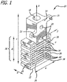
- Fig. 1 is a simplified schematic of a z-leg isolator 10 designed in accordance with an illustrative embodiment of the present invention.
- the novel isolator 10 includes a first mounting structure 12, a second mounting structure 14, and a zigzag structure 16 connecting the first mounting structure 12 and second mounting structure 14.
- the first mounting structure 12 is attached to the shock source (e.g., the support structure) and the second mounting structure 14 is attached to the sensitive equipment (e.g., the IMU).
- the sensitive equipment is thus isolated from direct contact with the support structure: any shock or vibration loads in the support structure travel through the isolator 10 (and through the zigzag structure 16) before reaching the sensitive equipment.
- the zigzag structure 16 provides a path (or paths) for shock and vibration energy to travel between the first mounting structure 12 and the second mounting structure 14.
- this path includes a series of zigzag patterns that include a plurality of ninety degree bends. Because of the zigzag patterns, the path between the first and second mounting structures 12 and 14 is much longer than the straight-line distance between them. Thus, shocks and vibrations are attenuated by the series of bends and the elongated path provided by the zigzag structure 16.
- the first mounting structure 12 includes a plate 12 having dimensions a x b at the bottom web of the isolator 10 that can be bolted to the support structure (not shown).
- a through-hole 18 is bored through the length of the isolator 10 (along the x -axis) in the center of the device, from the upper end to the bottom mounting plate 12, to allow a bolt to be placed within, bolting the first mounting plate 12 to the support structure.
- the bolt should preferably be in contact with only the bottom mounting plate 12, not the entire length of the isolator 10 (to avoid providing a shorter path between the two mounting structures 12 and 14).
- the isolator 10 has a length c from top to bottom.
- the second mounting structure 14 includes a plate 14 at the upper end of the isolator 10, perpendicular to the first mounting plate 12 (in Fig. 1 , the second mounting plate 14 is parallel to the x-z plane and the first mounting plate 12 is parallel to the y-z plane).
- the second mounting plate 14 includes two through-holes 20 (parallel to the y -axis), which are used to bolt the isolator 10 to the sensitive equipment (not shown).
- the second mounting plate 14 is bolted to the sensitive equipment along the y-axis direction, while the first mounting plate 12 is bolted to the support structure along the x -axis.
- the second mounting structure 14 should be designed such that when it is attached to the sensitive equipment, the zigzag structure 16 is not in direct contact with the equipment.
- the isolator 10 includes two spacers 21 that keep the zigzag structure 16 and the mounting structures 12 and 14 from being in direct contact with the sensitive equipment. Shock and vibration loads are transferred from the isolator 10 to the sensitive equipment via the bolts connecting the second mounting plate 14 to the equipment.
- the zigzag structure 16 includes a series of horizontal plates 22 parallel to the bottom mounting plate 12 (and the y-z plane), each plate having dimensions a x b.
- the bottom mounting plate 12 is connected to the first horizontal plate 22 by two vertical structures 24 in the middle of the plates (one structure 24 is located a distance of about 1/3 a away from an edge of the plate 12 and the second structure 24 is located a distance of about 2/3 a away from the same edge).
- the first horizontal plate 22 is connected to the second horizontal plate 22 by two vertical structures 26 located at the edges of the plates (one at each edge).
- the second plate 22 is connected to the third plate 22 by two vertical structures 24 in the middle of the plates, similar to how the bottom plate 12 was connected to the first plate 22.
- the third plate 22 is connected to the fourth plate 22 by two vertical structures 26 at the edges of the plates.
- the remaining plates 22 are connected in a similar fashion, alternating between connecting paths in the middle and at the edges.
- the second mounting plate 14 is connected to (resting on) the last horizontal plate 22.
- the zigzag structure 16 can also be described as a rectangular block of dimensions a x b x d having a plurality of parallel horizontal slots cut out, alternating between a long slot 28 and a row of three slots 30 (one in the middle and two on either side cutting in through the edges).
- the different sections of the isolator 10 form a single piece of metal.
- the isolator 10 may be fabricated, for example, by using a mold or by cutting pieces (slots and through-holes) out of a solid block of metal.
- the isolator 10 is made from metal, but the invention is not limited thereto. Other materials such as composites may also be used without departing from the present teachings.
- the isolator 10 is made from a material such as stainless steel that is ductile and has a high fatigue strength to withstand any stress caused by flexure when the isolator 10 is subject to shock or vibration loads.
- Fig. 2 is a simplified schematic of an IMU isolation system 50 designed in accordance with an illustrative embodiment of the present invention.
- an IMU 52 is isolated from shocks and vibrations using four z-leg isolators 10 (only three isolators 10 are visible in Fig. 2 ). Any number of isolators 10 may be used in the isolation system 50.
- Four isolators 10 were chosen for this application for stability and because of the shape of the IMU 52.
- the isolators 10 are equally spaced around the IMU 52, ninety degrees apart from each other.
- each isolator 10 The upper mounting structure 14 of each isolator 10 is bolted to the IMU 52.
- the lower mounting structure 12 of each isolator 10 is bolted to a support structure 54 (which could be a missile body or bulkhead). Note that the IMU 52 is not in direct contact with the support structure 54.
- the isolators 10 are positioned so that the IMU 52 is elevated relative to the support structure 54, such that shock energy must travel through the isolator to couple to the IMU 52.
- the IMU 52 is also not in direct contact with the zigzag structures 16 of the isolators 10, forcing shock energy to travel through the zigzag path before being transmitted to the IMU 52.
- shock input from the support structure 54 starts from the isolator's bottom web 12 and travels to the upper end 14 of the isolator 10 where the IMU 52 is attached.
- shock travels through the isolator's zigzag flexures its amplitude attenuates each time shock is forced to bend ninety degrees.
- the residual left over shock gets into the IMU 52 via the bolt joint interface between the isolator 10 and the IMU 52.
- shock attenuation is most effective at high frequencies (about 1 kHz to 10 kHz). Shock may be amplified, however, at the resonant frequency of the overall system 50.
- the z-leg isolators 10 may be tuned by adjusting the dimensions of the isolators so that the resonant frequency of the system 50 is at a desired frequency (such as a frequency where shocks and vibrations are less harmful to the IMU 52).
- the physical components of a typical IMU 52 are more sensitive to shocks at high frequencies of about 1000 Hz and above. Large shocks at these frequencies may physically damage the IMU components.
- the IMU output signal (data stream) is only responsive to frequencies below its bandwidth (typically about 200 Hz). The IMU output will not respond to frequencies above its bandwidth.
- the resonant frequency of the system 50 should therefore be moved to a frequency that is above 200 Hz and below 1000 Hz to minimize harmful effects to the IMU 52.
- the dimensions of the z-leg isolators 10 are chosen to provide a system resonant frequency at about 400 Hz.
- the amplification level at resonant frequency may be reduced by filling the slots (28 and 30) of each isolator 10 with a high damping material such as rubber or some other elastomeric.
- a high damping material such as rubber or some other elastomeric.
- the slots of each isolator 10 are filled with a silicone rubber having a hardness of 60A shore durometer. A lower hardness rubber may provide higher damping.
Landscapes
- Engineering & Computer Science (AREA)
- General Engineering & Computer Science (AREA)
- Mechanical Engineering (AREA)
- Vibration Prevention Devices (AREA)
- Springs (AREA)
- Vibration Dampers (AREA)
Description
- The present invention relates to shock and vibration isolators. More specifically, the present invention relates to systems and methods for isolating sensitive equipment from shock and vibration.
- In certain applications, it is imperative that sensitive equipment is isolated from shock and vibration forces to prevent faulty readings or damage. For example, an inertial measurement unit (IMU) of a missile typically contains fiber optic gyros, accelerometers, and other circuits that are very sensitive to launch shock and pyroshock events that can occur during flight. As a result of these high shock inputs, IMU components can break or produce erroneous bias signals, causing the missile guidance system to fail.
- To avoid this problem, the shock input level must be reduced by at least an order of magnitude. A common method for attenuating shock is to use isolators. Isolators are structures typically made from an elastomeric material such as rubber, that isolate the sensitive equipment from the shock source: e.g., the structure to which the equipment is mounted, such as the missile body. In an IMU, a layer of elastomeric material is often sandwiched between the IMU and the shock source to attenuate shock inputs.
- A problem with elastomerics is that their mechanical properties - such as elasticity, resiliency, and creep - change over time, causing system misalignments and uncertain effectiveness of shock isolation at the time of use. This can be a significant problem for applications such as missiles where the equipment may be stored for long periods of time - typically several years - before being used.
- Hence, a need exists in the art for an improved system or method for isolating sensitive equipment from shock and vibration that is more stable over time that prior approaches.
-
GB554944 GB554944 US2002/0079627 describes a shock isolator comprising an elastomeric shock cell. - The need in the art is addressed by the isolator of the present invention. The novel isolator includes a first mounting structure, a second mounting structure, and a structure for providing a path between the first and second mounting structures, this path having a series of zigzag patterns adapted to attenuate shock and/or vibration energy. The zigzag pattern provided between the first and second mounting structures forms a plurality of slots between a series of plates. A high damping material is disposed within one or more of these slots. The first mounting structure is attached to the shock source, and the second mounting structure is attached to the device to be isolated. In an illustrative embodiment, the isolator provides a path having a series of ninety-degree bends and a length greater than a direct distance between the first and second mounting structures. The path length and number of bends is tuned to provide a desired attenuation level. The dimensions of the isolator may also be tuned to provide a desired resonant frequency. The isolator is made from metal or a composite material having stable properties over time.
-
-
Fig. 1 is a simplified schematic of an isolator designed in accordance with an illustrative embodiment of the present invention. -
Fig. 2 is a simplified schematic of an IMU isolation system designed in accordance with an illustrative embodiment of the present invention. - Illustrative embodiments and exemplary applications will now be described with reference to the accompanying drawings to disclose the advantageous teachings of the present invention.
- While the present invention is described herein with reference to illustrative embodiments for particular applications, it should be understood that the invention is not limited thereto. Those having ordinary skill in the art and access to the teachings provided herein will recognize additional modifications, applications, and embodiments within the scope thereof and additional fields in which the present invention would be of significant utility.
- The present invention teaches a novel isolator design suitable for metals and other materials that are more stable over time than elastomerics. Metals (and other materials such as composites) typically have mechanical properties that do not change over time, therefore alignments and other dynamic characteristics of a metal isolator should stay the same from the time it is built to the time of actual usage. Metal, however, is not a high damping material like rubber and other elastomerics. Simply placing a layer of metal between the sensitive equipment and the shock source typically will not provide sufficient shock attenuation. A different design approach is therefore needed for a metal isolator.
- By nature, shock attenuation is proportional with its travel distance (the longer the travel distance, the smaller the shock amplitude). Shock is also attenuated if its travel path is bent from a straight line. The present invention applies these two principals to design a novel "z-leg" isolator having a series of zigzag patterns. These zigzag patterns lengthen the travel distance and also bend the shock travel paths with multiple ninety-degree angles.
-
Fig. 1 is a simplified schematic of a z-leg isolator 10 designed in accordance with an illustrative embodiment of the present invention. Thenovel isolator 10 includes afirst mounting structure 12, asecond mounting structure 14, and azigzag structure 16 connecting thefirst mounting structure 12 andsecond mounting structure 14. Thefirst mounting structure 12 is attached to the shock source (e.g., the support structure) and thesecond mounting structure 14 is attached to the sensitive equipment (e.g., the IMU). The sensitive equipment is thus isolated from direct contact with the support structure: any shock or vibration loads in the support structure travel through the isolator 10 (and through the zigzag structure 16) before reaching the sensitive equipment. - The
zigzag structure 16 provides a path (or paths) for shock and vibration energy to travel between thefirst mounting structure 12 and thesecond mounting structure 14. In accordance with the present teachings, this path includes a series of zigzag patterns that include a plurality of ninety degree bends. Because of the zigzag patterns, the path between the first andsecond mounting structures zigzag structure 16. - In the illustrative embodiment shown in
Fig. 1 , thefirst mounting structure 12 includes aplate 12 having dimensions a x b at the bottom web of theisolator 10 that can be bolted to the support structure (not shown). A through-hole 18 is bored through the length of the isolator 10 (along the x-axis) in the center of the device, from the upper end to thebottom mounting plate 12, to allow a bolt to be placed within, bolting thefirst mounting plate 12 to the support structure. After assembly, the bolt should preferably be in contact with only thebottom mounting plate 12, not the entire length of the isolator 10 (to avoid providing a shorter path between the twomounting structures 12 and 14). As shown inFig. 1 , theisolator 10 has a length c from top to bottom. - The
second mounting structure 14 includes aplate 14 at the upper end of theisolator 10, perpendicular to the first mounting plate 12 (inFig. 1 , thesecond mounting plate 14 is parallel to the x-z plane and thefirst mounting plate 12 is parallel to the y-z plane). Thesecond mounting plate 14 includes two through-holes 20 (parallel to the y-axis), which are used to bolt theisolator 10 to the sensitive equipment (not shown). Thesecond mounting plate 14 is bolted to the sensitive equipment along the y-axis direction, while thefirst mounting plate 12 is bolted to the support structure along the x-axis. Thesecond mounting structure 14 should be designed such that when it is attached to the sensitive equipment, thezigzag structure 16 is not in direct contact with the equipment. In the embodiment ofFig. 1 , theisolator 10 includes twospacers 21 that keep thezigzag structure 16 and themounting structures isolator 10 to the sensitive equipment via the bolts connecting thesecond mounting plate 14 to the equipment. - The
zigzag structure 16 includes a series ofhorizontal plates 22 parallel to the bottom mounting plate 12 (and the y-z plane), each plate having dimensions a x b. Thebottom mounting plate 12 is connected to the firsthorizontal plate 22 by twovertical structures 24 in the middle of the plates (onestructure 24 is located a distance of about 1/3 a away from an edge of theplate 12 and thesecond structure 24 is located a distance of about 2/3 a away from the same edge). The firsthorizontal plate 22 is connected to the secondhorizontal plate 22 by twovertical structures 26 located at the edges of the plates (one at each edge). Thesecond plate 22 is connected to thethird plate 22 by twovertical structures 24 in the middle of the plates, similar to how thebottom plate 12 was connected to thefirst plate 22. Thethird plate 22 is connected to thefourth plate 22 by twovertical structures 26 at the edges of the plates. The remainingplates 22 are connected in a similar fashion, alternating between connecting paths in the middle and at the edges. Thesecond mounting plate 14 is connected to (resting on) the lasthorizontal plate 22. Thus, shock energy from thebottom mounting plate 12 is forced to travel through an elongated path containing a series of ninety-degree bends in thezigzag structure 16 before it reaches the top mountingplate 14. - The
zigzag structure 16 can also be described as a rectangular block of dimensions a x b x d having a plurality of parallel horizontal slots cut out, alternating between along slot 28 and a row of three slots 30 (one in the middle and two on either side cutting in through the edges). - In the illustrative embodiment, the different sections of the isolator 10 (including the
first mounting structure 12, thesecond mounting structure 14, and the zigzag structure 16) form a single piece of metal. Theisolator 10 may be fabricated, for example, by using a mold or by cutting pieces (slots and through-holes) out of a solid block of metal. - In the illustrative embodiment, the
isolator 10 is made from metal, but the invention is not limited thereto. Other materials such as composites may also be used without departing from the present teachings. In a preferred embodiment, theisolator 10 is made from a material such as stainless steel that is ductile and has a high fatigue strength to withstand any stress caused by flexure when theisolator 10 is subject to shock or vibration loads. -
Fig. 2 is a simplified schematic of anIMU isolation system 50 designed in accordance with an illustrative embodiment of the present invention. In the illustrative embodiment, anIMU 52 is isolated from shocks and vibrations using four z-leg isolators 10 (only threeisolators 10 are visible inFig. 2 ). Any number ofisolators 10 may be used in theisolation system 50. Fourisolators 10 were chosen for this application for stability and because of the shape of theIMU 52. Theisolators 10 are equally spaced around theIMU 52, ninety degrees apart from each other. - The
upper mounting structure 14 of each isolator 10 is bolted to theIMU 52. Thelower mounting structure 12 of each isolator 10 is bolted to a support structure 54 (which could be a missile body or bulkhead). Note that theIMU 52 is not in direct contact with the support structure 54. Theisolators 10 are positioned so that theIMU 52 is elevated relative to the support structure 54, such that shock energy must travel through the isolator to couple to theIMU 52. TheIMU 52 is also not in direct contact with thezigzag structures 16 of theisolators 10, forcing shock energy to travel through the zigzag path before being transmitted to theIMU 52. - During a shock event, shock input from the support structure 54 starts from the isolator's
bottom web 12 and travels to theupper end 14 of theisolator 10 where theIMU 52 is attached. As shock travels through the isolator's zigzag flexures, its amplitude attenuates each time shock is forced to bend ninety degrees. At the end of travel, the residual left over shock gets into theIMU 52 via the bolt joint interface between the isolator 10 and theIMU 52. By tuning the number of ninety-degree turns and the total shock travel length, a desired shock attenuation level can be attained. - In the illustrative embodiment, shock attenuation is most effective at high frequencies (about 1 kHz to 10 kHz). Shock may be amplified, however, at the resonant frequency of the
overall system 50. In accordance with the present teachings, the z-leg isolators 10 may be tuned by adjusting the dimensions of the isolators so that the resonant frequency of thesystem 50 is at a desired frequency (such as a frequency where shocks and vibrations are less harmful to the IMU 52). - For example, the physical components of a
typical IMU 52 are more sensitive to shocks at high frequencies of about 1000 Hz and above. Large shocks at these frequencies may physically damage the IMU components. The IMU output signal (data stream) is only responsive to frequencies below its bandwidth (typically about 200 Hz). The IMU output will not respond to frequencies above its bandwidth. For this illustrative application, the resonant frequency of thesystem 50 should therefore be moved to a frequency that is above 200 Hz and below 1000 Hz to minimize harmful effects to theIMU 52. In an illustrative embodiment, the dimensions of the z-leg isolators 10 are chosen to provide a system resonant frequency at about 400 Hz. - The amplification level at resonant frequency may be reduced by filling the slots (28 and 30) of each isolator 10 with a high damping material such as rubber or some other elastomeric. In an illustrative embodiment, the slots of each isolator 10 are filled with a silicone rubber having a hardness of 60A shore durometer. A lower hardness rubber may provide higher damping.
- Thus, the present invention has been described herein with reference to a particular embodiment for a particular application. Those having ordinary skill in the art and access to the present teachings will recognize additional modifications, applications and embodiments within the scope thereof. For example, while the invention has been described with reference to an IMU application, the novel z-leg isolator may also be used in other applications to attenuate shocks and/or vibration.
- It is therefore intended by the appended claims to cover any and all such applications, modifications and embodiments within the scope of the present invention.
Claims (6)
- An isolator (10) comprising:a first mounting structure (12);a second mounting structure (14); anda zigzag structure (16) connecting the first mounting structure (12) and the second mounting structure (14), the zigzag structure (16) comprising a series of plates (22) parallel to the first mounting structure (12),wherein the first mounting structure (12) is connected to a first plate (22) of the series of plates (22) by two vertical structures (24) in the middle of the plates,
the first plate (22) is connected to a second plate (22) in the series of plates by two vertical structures (26) at the edges of the plates, and wherein the remaining plates (22) of the series of plates (22) are connected in an alternating manner between the vertical structures (24) in the middle of the plates and the vertical structures (26) at the edges of the plates; and the second mounting structure (14) is connected to the last plate (22) in the series of plates, wherein the series of plates (22) and vertical structures (22, 24) provide a path between first and second mounting structures (12, 14), said path having a series of zigzag patterns comprising ninety-degree bends adapted to attenuate shock and/or vibration energy,
wherein said zigzag pattern forms a plurality of slots between the plates (22), characterised in that said isolator (10) is made from metal or from a composite material and further includes a high damping material disposed within one or more of said slots. - The isolator (10) of claim 1 wherein said path has a length substantially greater than direct distance between said first and second mounting structure (12, 14), the length including the ninety-degree bends, the length being selected to provide a desired attenuation level.
- The isolator of claim 1 wherein said first mounting structure (12) includes a first mounting plate,
wherein said second mounting structure (14) includes a second mounting plate, and
wherein said first mounting plate is perpendicular to said second mounting plate. - The isolator of claim 1 wherein said first mounting structure (12) includes one or more through-holes (18) for bolting said first mounting structure (12) to a support structure,
wherein said second mounting structure (14) includes one or more through-holes (18) for bolting said second mounting structure (14) to a device to be isolated. - The isolator (10) of claim 1 wherein dimensions of said isolator (10) are adapted to provide a desired resonant frequency.
- A method for isolating a device from a support structure including the steps of:attaching a first end (12) of an isolator to said support structure;attaching a second end (14) of said isolator to said device; andproviding a path between said first and second ends (12, 14) of said isolator, a zigzag structure (16) for providing a path between said first and second mounting structures (12, 14), wherein the zigzag structure (16) comprises a series of plates (22) parallel to the first mounting structure (12), wherein the plates are coupled between first and second mounting structures (12, 14),wherein the first mounting structure (12) is connected to a first plate (22) of the series of plates (22) by two vertical structures (24) in the middle of the plates,
the first plate (22) is connected to a second plate (22) in the series of plates by two vertical structures (26) at the edges of the plates, and wherein the remaining plates (22) of the series of plates (22) are connected in an alternating manner between the vertical structures (24) in the middle of the plates and the vertical structures (26) at the edges of the plates; and the second mounting structure (14) is connected to the last plate (22) in the series of plates , wherein the series of plates (22) and vertical structures (22, 24), said path having a series of zigzag patterns comprising ninety-degree bends adapted to attenuate shock and/or vibration energy and wherein said zigzag pattern forms a plurality of slots between the plates, and wherein said isolator is made from metal or from a composite material and further includes a high damping material disposed within one or more of said slots.
Applications Claiming Priority (2)
| Application Number | Priority Date | Filing Date | Title |
|---|---|---|---|
| US11/895,316 US8262051B2 (en) | 2007-08-23 | 2007-08-23 | Z-leg shock isolator |
| PCT/US2008/009724 WO2009029171A1 (en) | 2007-08-23 | 2008-08-14 | Z-leg shock isolator |
Publications (3)
| Publication Number | Publication Date |
|---|---|
| EP2191163A1 EP2191163A1 (en) | 2010-06-02 |
| EP2191163A4 EP2191163A4 (en) | 2016-09-14 |
| EP2191163B1 true EP2191163B1 (en) | 2019-01-09 |
Family
ID=40387638
Family Applications (1)
| Application Number | Title | Priority Date | Filing Date |
|---|---|---|---|
| EP08828213.2A Active EP2191163B1 (en) | 2007-08-23 | 2008-08-14 | Z-leg shock isolator and isolation method |
Country Status (4)
| Country | Link |
|---|---|
| US (1) | US8262051B2 (en) |
| EP (1) | EP2191163B1 (en) |
| JP (1) | JP2011504565A (en) |
| WO (1) | WO2009029171A1 (en) |
Families Citing this family (12)
| Publication number | Priority date | Publication date | Assignee | Title |
|---|---|---|---|---|
| US8262051B2 (en) | 2007-08-23 | 2012-09-11 | Raytheon Company | Z-leg shock isolator |
| FR2949250B1 (en) * | 2009-08-24 | 2012-01-06 | Aliaxis R & D Sas | AMORTIZING BRIDGE |
| US9033301B1 (en) * | 2011-04-26 | 2015-05-19 | The Boeing Company | Vibration reduction system using an extended washer |
| GB201417414D0 (en) | 2014-10-02 | 2014-11-19 | Rolls Royce Plc | Fixture apparatus |
| CN106882399B (en) * | 2015-12-16 | 2018-12-25 | 北京空间技术研制试验中心 | Spacecraft equipment surge guard device |
| WO2018183400A1 (en) | 2017-03-27 | 2018-10-04 | Hutchinson Aerospace & Industry, Inc. | A continuous framework for shock, vibration and thermal isolation and motion accommodation |
| US10480613B2 (en) | 2018-04-11 | 2019-11-19 | Raytheon Company | Metal isolator with tunable resonant frequencies |
| US10933525B2 (en) * | 2018-07-04 | 2021-03-02 | Fanuc Corporation | Horizontal articulated robot |
| US12480558B2 (en) | 2021-08-10 | 2025-11-25 | Raytheon Company | 3-axis tunable metal isolator |
| US12297885B2 (en) | 2022-04-28 | 2025-05-13 | Raytheon Company | Shock isolator with flexures and stop mechanism |
| US12173748B2 (en) | 2022-06-03 | 2024-12-24 | Raytheon Company | Structural joint isolator with internal cavities |
| US12560415B2 (en) * | 2023-11-17 | 2026-02-24 | Raytheon Company | Integrally formed high-G shock metal isolator in a projectile |
Family Cites Families (17)
| Publication number | Priority date | Publication date | Assignee | Title |
|---|---|---|---|---|
| GB554944A (en) | 1940-10-15 | 1943-07-27 | Lord Mfg Co | Improvement in or relating to resilient supports for articles subject to shock or vibration |
| US2678685A (en) * | 1948-02-27 | 1954-05-18 | Nicholas T Volsk | Flat spring and structure |
| FR1090004A (en) * | 1953-07-22 | 1955-03-25 | Spring | |
| GB8500605D0 (en) * | 1985-01-10 | 1985-02-13 | Secretary Trade Ind Brit | Damped spring |
| FR2631668B2 (en) * | 1988-01-15 | 1993-11-12 | Hutchinson | ELASTIC SUSPENSION SUPPORTS |
| US5197698A (en) * | 1991-03-25 | 1993-03-30 | Proprietary Technology, Inc. | Method of mounting and isolating automotive exhaust systems |
| GB2269647B (en) * | 1992-08-14 | 1996-05-01 | Sulcated Springs Limited | Compliant support system |
| US5746419A (en) * | 1996-10-16 | 1998-05-05 | General Motors Corporation | Energy absorbing device |
| US6345814B1 (en) * | 2000-09-20 | 2002-02-12 | Visteon Global Technologies, Inc. | Composite progressive accordion spring |
| US20020079627A1 (en) * | 2000-12-22 | 2002-06-27 | Mccollough Trevor J. | Shock isolator |
| JP3967647B2 (en) * | 2002-08-28 | 2007-08-29 | 小島プレス工業株式会社 | Shock absorbing structure for vehicle |
| AU2003257809A1 (en) * | 2002-10-31 | 2004-05-25 | Kyoraku Co., Ltd. | Impact absorbing body for vehicle |
| US7735812B2 (en) * | 2003-04-30 | 2010-06-15 | Trelleborg Ab | Vibration-damping device |
| JP4048156B2 (en) * | 2003-06-30 | 2008-02-13 | 東海ゴム工業株式会社 | Fluid filled vibration isolator |
| US20070053168A1 (en) * | 2004-01-21 | 2007-03-08 | General Electric Company | Advanced heat sinks and thermal spreaders |
| EP1748216B1 (en) * | 2005-07-25 | 2015-04-22 | General Electric Company | Suspension system |
| US8262051B2 (en) | 2007-08-23 | 2012-09-11 | Raytheon Company | Z-leg shock isolator |
-
2007
- 2007-08-23 US US11/895,316 patent/US8262051B2/en active Active
-
2008
- 2008-08-14 WO PCT/US2008/009724 patent/WO2009029171A1/en not_active Ceased
- 2008-08-14 EP EP08828213.2A patent/EP2191163B1/en active Active
- 2008-08-14 JP JP2010521855A patent/JP2011504565A/en active Pending
Non-Patent Citations (1)
| Title |
|---|
| None * |
Also Published As
| Publication number | Publication date |
|---|---|
| EP2191163A1 (en) | 2010-06-02 |
| WO2009029171A4 (en) | 2009-05-07 |
| US8262051B2 (en) | 2012-09-11 |
| JP2011504565A (en) | 2011-02-10 |
| US20100327142A1 (en) | 2010-12-30 |
| WO2009029171A1 (en) | 2009-03-05 |
| EP2191163A4 (en) | 2016-09-14 |
Similar Documents
| Publication | Publication Date | Title |
|---|---|---|
| US8262051B2 (en) | Z-leg shock isolator | |
| US12038061B2 (en) | Tuned mass absorber assembly and system for attenuating frequency specific vibrational energy | |
| US9086112B2 (en) | Instrumented platform for vibration-sensitive equipment | |
| US20070131504A1 (en) | Planar vibration absorber | |
| US3322377A (en) | Anti-vibration resilient supports | |
| KR101701810B1 (en) | Seismic equipment | |
| AU2019253149B2 (en) | Metal isolator with tunable resonant frequencies and method for making the isolator | |
| EP3530980A1 (en) | Anti-vibration support system | |
| JP6697488B2 (en) | Lightweight passive attenuator for spacecraft | |
| US6286782B1 (en) | Apparatus and method for reducing vibrations of a structure particularly a helicopter | |
| US5478058A (en) | Shock isolation method and apparatus | |
| US8276873B2 (en) | Instrumented platform for vibration-sensitive equipment | |
| US11505335B2 (en) | Damper for an object placed in a medium subjected to vibrations and corresponding damper system | |
| US9810279B2 (en) | Vibratory bandgap device | |
| EP4165262B1 (en) | Structural bearing for protecting structures against shocks | |
| JPH02248550A (en) | Device for exempting lightweight building from vibration | |
| HK40089719A (en) | Structural bearing for protecting structures against shocks | |
| HK40089719B (en) | Structural bearing for protecting structures against shocks | |
| JP2017180532A (en) | Shock absorber | |
| JPH03234944A (en) | Vibration-removing support device | |
| JP2006258260A (en) | Vibration isolator | |
| SE521426C2 (en) | Suppressed suspension arrangement |
Legal Events
| Date | Code | Title | Description |
|---|---|---|---|
| PUAI | Public reference made under article 153(3) epc to a published international application that has entered the european phase |
Free format text: ORIGINAL CODE: 0009012 |
|
| 17P | Request for examination filed |
Effective date: 20100323 |
|
| AK | Designated contracting states |
Kind code of ref document: A1 Designated state(s): AT BE BG CH CY CZ DE DK EE ES FI FR GB GR HR HU IE IS IT LI LT LU LV MC MT NL NO PL PT RO SE SI SK TR |
|
| AX | Request for extension of the european patent |
Extension state: AL BA MK RS |
|
| DAX | Request for extension of the european patent (deleted) | ||
| RA4 | Supplementary search report drawn up and despatched (corrected) |
Effective date: 20160816 |
|
| RIC1 | Information provided on ipc code assigned before grant |
Ipc: F16F 1/377 20060101ALI20160809BHEP Ipc: F16F 1/20 20060101AFI20160809BHEP |
|
| STAA | Information on the status of an ep patent application or granted ep patent |
Free format text: STATUS: EXAMINATION IS IN PROGRESS |
|
| 17Q | First examination report despatched |
Effective date: 20170913 |
|
| GRAP | Despatch of communication of intention to grant a patent |
Free format text: ORIGINAL CODE: EPIDOSNIGR1 |
|
| STAA | Information on the status of an ep patent application or granted ep patent |
Free format text: STATUS: GRANT OF PATENT IS INTENDED |
|
| INTG | Intention to grant announced |
Effective date: 20180518 |
|
| GRAS | Grant fee paid |
Free format text: ORIGINAL CODE: EPIDOSNIGR3 |
|
| GRAJ | Information related to disapproval of communication of intention to grant by the applicant or resumption of examination proceedings by the epo deleted |
Free format text: ORIGINAL CODE: EPIDOSDIGR1 |
|
| GRAL | Information related to payment of fee for publishing/printing deleted |
Free format text: ORIGINAL CODE: EPIDOSDIGR3 |
|
| STAA | Information on the status of an ep patent application or granted ep patent |
Free format text: STATUS: EXAMINATION IS IN PROGRESS |
|
| GRAP | Despatch of communication of intention to grant a patent |
Free format text: ORIGINAL CODE: EPIDOSNIGR1 |
|
| STAA | Information on the status of an ep patent application or granted ep patent |
Free format text: STATUS: GRANT OF PATENT IS INTENDED |
|
| INTC | Intention to grant announced (deleted) | ||
| INTG | Intention to grant announced |
Effective date: 20181022 |
|
| GRAA | (expected) grant |
Free format text: ORIGINAL CODE: 0009210 |
|
| STAA | Information on the status of an ep patent application or granted ep patent |
Free format text: STATUS: THE PATENT HAS BEEN GRANTED |
|
| AK | Designated contracting states |
Kind code of ref document: B1 Designated state(s): AT BE BG CH CY CZ DE DK EE ES FI FR GB GR HR HU IE IS IT LI LT LU LV MC MT NL NO PL PT RO SE SI SK TR |
|
| REG | Reference to a national code |
Ref country code: GB Ref legal event code: FG4D |
|
| REG | Reference to a national code |
Ref country code: CH Ref legal event code: EP Ref country code: AT Ref legal event code: REF Ref document number: 1087692 Country of ref document: AT Kind code of ref document: T Effective date: 20190115 |
|
| REG | Reference to a national code |
Ref country code: DE Ref legal event code: R096 Ref document number: 602008058706 Country of ref document: DE |
|
| REG | Reference to a national code |
Ref country code: IE Ref legal event code: FG4D |
|
| REG | Reference to a national code |
Ref country code: NL Ref legal event code: MP Effective date: 20190109 |
|
| REG | Reference to a national code |
Ref country code: LT Ref legal event code: MG4D |
|
| PG25 | Lapsed in a contracting state [announced via postgrant information from national office to epo] |
Ref country code: NL Free format text: LAPSE BECAUSE OF FAILURE TO SUBMIT A TRANSLATION OF THE DESCRIPTION OR TO PAY THE FEE WITHIN THE PRESCRIBED TIME-LIMIT Effective date: 20190109 |
|
| REG | Reference to a national code |
Ref country code: AT Ref legal event code: MK05 Ref document number: 1087692 Country of ref document: AT Kind code of ref document: T Effective date: 20190109 |
|
| PG25 | Lapsed in a contracting state [announced via postgrant information from national office to epo] |
Ref country code: FI Free format text: LAPSE BECAUSE OF FAILURE TO SUBMIT A TRANSLATION OF THE DESCRIPTION OR TO PAY THE FEE WITHIN THE PRESCRIBED TIME-LIMIT Effective date: 20190109 Ref country code: NO Free format text: LAPSE BECAUSE OF FAILURE TO SUBMIT A TRANSLATION OF THE DESCRIPTION OR TO PAY THE FEE WITHIN THE PRESCRIBED TIME-LIMIT Effective date: 20190409 Ref country code: LT Free format text: LAPSE BECAUSE OF FAILURE TO SUBMIT A TRANSLATION OF THE DESCRIPTION OR TO PAY THE FEE WITHIN THE PRESCRIBED TIME-LIMIT Effective date: 20190109 Ref country code: ES Free format text: LAPSE BECAUSE OF FAILURE TO SUBMIT A TRANSLATION OF THE DESCRIPTION OR TO PAY THE FEE WITHIN THE PRESCRIBED TIME-LIMIT Effective date: 20190109 Ref country code: PT Free format text: LAPSE BECAUSE OF FAILURE TO SUBMIT A TRANSLATION OF THE DESCRIPTION OR TO PAY THE FEE WITHIN THE PRESCRIBED TIME-LIMIT Effective date: 20190509 Ref country code: PL Free format text: LAPSE BECAUSE OF FAILURE TO SUBMIT A TRANSLATION OF THE DESCRIPTION OR TO PAY THE FEE WITHIN THE PRESCRIBED TIME-LIMIT Effective date: 20190109 Ref country code: SE Free format text: LAPSE BECAUSE OF FAILURE TO SUBMIT A TRANSLATION OF THE DESCRIPTION OR TO PAY THE FEE WITHIN THE PRESCRIBED TIME-LIMIT Effective date: 20190109 |
|
| PG25 | Lapsed in a contracting state [announced via postgrant information from national office to epo] |
Ref country code: HR Free format text: LAPSE BECAUSE OF FAILURE TO SUBMIT A TRANSLATION OF THE DESCRIPTION OR TO PAY THE FEE WITHIN THE PRESCRIBED TIME-LIMIT Effective date: 20190109 Ref country code: LV Free format text: LAPSE BECAUSE OF FAILURE TO SUBMIT A TRANSLATION OF THE DESCRIPTION OR TO PAY THE FEE WITHIN THE PRESCRIBED TIME-LIMIT Effective date: 20190109 Ref country code: IS Free format text: LAPSE BECAUSE OF FAILURE TO SUBMIT A TRANSLATION OF THE DESCRIPTION OR TO PAY THE FEE WITHIN THE PRESCRIBED TIME-LIMIT Effective date: 20190509 Ref country code: BG Free format text: LAPSE BECAUSE OF FAILURE TO SUBMIT A TRANSLATION OF THE DESCRIPTION OR TO PAY THE FEE WITHIN THE PRESCRIBED TIME-LIMIT Effective date: 20190409 Ref country code: GR Free format text: LAPSE BECAUSE OF FAILURE TO SUBMIT A TRANSLATION OF THE DESCRIPTION OR TO PAY THE FEE WITHIN THE PRESCRIBED TIME-LIMIT Effective date: 20190410 |
|
| REG | Reference to a national code |
Ref country code: DE Ref legal event code: R097 Ref document number: 602008058706 Country of ref document: DE |
|
| PG25 | Lapsed in a contracting state [announced via postgrant information from national office to epo] |
Ref country code: AT Free format text: LAPSE BECAUSE OF FAILURE TO SUBMIT A TRANSLATION OF THE DESCRIPTION OR TO PAY THE FEE WITHIN THE PRESCRIBED TIME-LIMIT Effective date: 20190109 Ref country code: DK Free format text: LAPSE BECAUSE OF FAILURE TO SUBMIT A TRANSLATION OF THE DESCRIPTION OR TO PAY THE FEE WITHIN THE PRESCRIBED TIME-LIMIT Effective date: 20190109 Ref country code: EE Free format text: LAPSE BECAUSE OF FAILURE TO SUBMIT A TRANSLATION OF THE DESCRIPTION OR TO PAY THE FEE WITHIN THE PRESCRIBED TIME-LIMIT Effective date: 20190109 Ref country code: IT Free format text: LAPSE BECAUSE OF FAILURE TO SUBMIT A TRANSLATION OF THE DESCRIPTION OR TO PAY THE FEE WITHIN THE PRESCRIBED TIME-LIMIT Effective date: 20190109 Ref country code: RO Free format text: LAPSE BECAUSE OF FAILURE TO SUBMIT A TRANSLATION OF THE DESCRIPTION OR TO PAY THE FEE WITHIN THE PRESCRIBED TIME-LIMIT Effective date: 20190109 Ref country code: CZ Free format text: LAPSE BECAUSE OF FAILURE TO SUBMIT A TRANSLATION OF THE DESCRIPTION OR TO PAY THE FEE WITHIN THE PRESCRIBED TIME-LIMIT Effective date: 20190109 Ref country code: SK Free format text: LAPSE BECAUSE OF FAILURE TO SUBMIT A TRANSLATION OF THE DESCRIPTION OR TO PAY THE FEE WITHIN THE PRESCRIBED TIME-LIMIT Effective date: 20190109 |
|
| PLBE | No opposition filed within time limit |
Free format text: ORIGINAL CODE: 0009261 |
|
| STAA | Information on the status of an ep patent application or granted ep patent |
Free format text: STATUS: NO OPPOSITION FILED WITHIN TIME LIMIT |
|
| 26N | No opposition filed |
Effective date: 20191010 |
|
| PG25 | Lapsed in a contracting state [announced via postgrant information from national office to epo] |
Ref country code: SI Free format text: LAPSE BECAUSE OF FAILURE TO SUBMIT A TRANSLATION OF THE DESCRIPTION OR TO PAY THE FEE WITHIN THE PRESCRIBED TIME-LIMIT Effective date: 20190109 |
|
| PG25 | Lapsed in a contracting state [announced via postgrant information from national office to epo] |
Ref country code: TR Free format text: LAPSE BECAUSE OF FAILURE TO SUBMIT A TRANSLATION OF THE DESCRIPTION OR TO PAY THE FEE WITHIN THE PRESCRIBED TIME-LIMIT Effective date: 20190109 |
|
| PG25 | Lapsed in a contracting state [announced via postgrant information from national office to epo] |
Ref country code: LU Free format text: LAPSE BECAUSE OF NON-PAYMENT OF DUE FEES Effective date: 20190814 Ref country code: CH Free format text: LAPSE BECAUSE OF NON-PAYMENT OF DUE FEES Effective date: 20190831 Ref country code: MC Free format text: LAPSE BECAUSE OF FAILURE TO SUBMIT A TRANSLATION OF THE DESCRIPTION OR TO PAY THE FEE WITHIN THE PRESCRIBED TIME-LIMIT Effective date: 20190109 Ref country code: LI Free format text: LAPSE BECAUSE OF NON-PAYMENT OF DUE FEES Effective date: 20190831 |
|
| REG | Reference to a national code |
Ref country code: BE Ref legal event code: MM Effective date: 20190831 |
|
| PG25 | Lapsed in a contracting state [announced via postgrant information from national office to epo] |
Ref country code: IE Free format text: LAPSE BECAUSE OF NON-PAYMENT OF DUE FEES Effective date: 20190814 |
|
| PG25 | Lapsed in a contracting state [announced via postgrant information from national office to epo] |
Ref country code: BE Free format text: LAPSE BECAUSE OF NON-PAYMENT OF DUE FEES Effective date: 20190831 |
|
| PG25 | Lapsed in a contracting state [announced via postgrant information from national office to epo] |
Ref country code: CY Free format text: LAPSE BECAUSE OF FAILURE TO SUBMIT A TRANSLATION OF THE DESCRIPTION OR TO PAY THE FEE WITHIN THE PRESCRIBED TIME-LIMIT Effective date: 20190109 |
|
| PG25 | Lapsed in a contracting state [announced via postgrant information from national office to epo] |
Ref country code: MT Free format text: LAPSE BECAUSE OF FAILURE TO SUBMIT A TRANSLATION OF THE DESCRIPTION OR TO PAY THE FEE WITHIN THE PRESCRIBED TIME-LIMIT Effective date: 20190109 Ref country code: HU Free format text: LAPSE BECAUSE OF FAILURE TO SUBMIT A TRANSLATION OF THE DESCRIPTION OR TO PAY THE FEE WITHIN THE PRESCRIBED TIME-LIMIT; INVALID AB INITIO Effective date: 20080814 |
|
| P01 | Opt-out of the competence of the unified patent court (upc) registered |
Effective date: 20230530 |
|
| PGFP | Annual fee paid to national office [announced via postgrant information from national office to epo] |
Ref country code: DE Payment date: 20250724 Year of fee payment: 18 |
|
| PGFP | Annual fee paid to national office [announced via postgrant information from national office to epo] |
Ref country code: GB Payment date: 20250724 Year of fee payment: 18 |
|
| PGFP | Annual fee paid to national office [announced via postgrant information from national office to epo] |
Ref country code: FR Payment date: 20250725 Year of fee payment: 18 |