EP2191146B1 - Scroll type manifold for fans with an improved system for connection to a boiler structure or the like. - Google Patents
Scroll type manifold for fans with an improved system for connection to a boiler structure or the like. Download PDFInfo
- Publication number
- EP2191146B1 EP2191146B1 EP08804067A EP08804067A EP2191146B1 EP 2191146 B1 EP2191146 B1 EP 2191146B1 EP 08804067 A EP08804067 A EP 08804067A EP 08804067 A EP08804067 A EP 08804067A EP 2191146 B1 EP2191146 B1 EP 2191146B1
- Authority
- EP
- European Patent Office
- Prior art keywords
- manifold
- extension piece
- connection
- seat
- scroll type
- Prior art date
- Legal status (The legal status is an assumption and is not a legal conclusion. Google has not performed a legal analysis and makes no representation as to the accuracy of the status listed.)
- Active
Links
Images


Classifications
-
- F—MECHANICAL ENGINEERING; LIGHTING; HEATING; WEAPONS; BLASTING
- F04—POSITIVE - DISPLACEMENT MACHINES FOR LIQUIDS; PUMPS FOR LIQUIDS OR ELASTIC FLUIDS
- F04D—NON-POSITIVE-DISPLACEMENT PUMPS
- F04D29/00—Details, component parts, or accessories
- F04D29/60—Mounting; Assembling; Disassembling
- F04D29/601—Mounting; Assembling; Disassembling specially adapted for elastic fluid pumps
-
- F—MECHANICAL ENGINEERING; LIGHTING; HEATING; WEAPONS; BLASTING
- F04—POSITIVE - DISPLACEMENT MACHINES FOR LIQUIDS; PUMPS FOR LIQUIDS OR ELASTIC FLUIDS
- F04D—NON-POSITIVE-DISPLACEMENT PUMPS
- F04D29/00—Details, component parts, or accessories
- F04D29/40—Casings; Connections of working fluid
- F04D29/42—Casings; Connections of working fluid for radial or helico-centrifugal pumps
- F04D29/4206—Casings; Connections of working fluid for radial or helico-centrifugal pumps especially adapted for elastic fluid pumps
- F04D29/4226—Fan casings
Definitions
- the invention relates to a scroll type manifold for fans having the features set out in the preamble of main claim 1.
- This invention is used particularly, though not exclusively, in the construction of manifolds for electric fan units for boilers or similar devices.
- the scroll type manifold which is intended to receive the impeller of the fan as two half-shells which can be connected together so as to produce the volute of the manifold, inside which the said impeller is rotatably supported and is actuated by the relevant motor unit.
- the manifold is supported on a stationary structure of the boiler, by means of connection systems which provide for the interposition of brackets or similar structures, using removable fixing means, for example, screw type means.
- a scroll type manifold for fans having the features outlined above is known from the closest prior art document DE 1898022 .
- US7001149 and DE4217069 are also prior art to the present invention.
- manifold half-shells are constructed by pressure die-casting, it is known to provide, in at least one of the half-shells, a plurality of connection extension pieces which project from the manifold and which can readily be integrally formed with the body of the manifold, during the pressure die-casting operation, in such a manner as to act as connection formations in order to fix the manifold to the fixed structure of the boiler.
- connection formations for the fan which are integral with the body of the manifold.
- connection means such as brackets or similar structures, which are intended to be secured to the manifold makes the provision of the connection means more complex and difficult, in addition to the fact that, during the operations for mounting on the boiler, additional operations are required for positioning and centring the brackets with respect to the manifold.
- a main object of the invention is to provide a manifold and a system for connecting the manifold to a fixed structure of the boiler, which is structurally and functionally configured to overcome the limitations set out with reference to the prior art cited, in particular with reference to manifolds for electric fans which are constructed from stamped sheet metal.
- a scroll type manifold is generally designated 1 and is provided in order to constitute the housing of a radial impeller (not illustrated) of a fan, preferably an electric fan with a relevant electric drive motor.
- the manifold comprises a manifold body, in which there is defined an intake cross-section 2, which is provided laterally in the manifold, with an intake flow which is substantially coaxial relative to the axis of rotation of the fan and which is schematically indicated X in the Figures, and a delivery cross-section 3, in which the direction of the delivery flow which is indicated by the axis Y in the Figures is directed so as to be substantially perpendicular to the axis X.
- the manifold 1 is also constructed as two half-shells which are designated 1a, 1b, respectively, and which can be connected together in a manner known per se in a connection plane.
- the half-shells are preferably formed in a practically specularly symmetrical manner with respect to the connection plane, the plane therefore defining a median plane of substantial symmetry.
- the intake cross-section 2 of the fan comprising a lateral opening 2a which is coaxial with the axis X of the impeller.
- the half-shells 1a, 1b are advantageously constructed from sheet metal and are produced by a sheet metal stamping method, as an alternative to, for example, the conventional pressure die-casting technique.
- connection means which are generally designated 5 and described in detail below and which are configured in order to act between a connection surface which is provided in the boiler structure, which is schematically illustrated and designated 6, and the side wall 2b of the manifold having the intake opening 2a.
- the above-mentioned connection means comprise a plurality of connection extension pieces, all designated 7, which are structurally independent of the manifold and each of which is capable of engaging, at least partially, with a respective seat 8 which is provided in the manifold.
- each seat 8 is produced at the same time during the operation of stamping the half-shell 1a (from sheet metal) and is formed in such a manner as to construct a type of recess, in which at least part of the corresponding connection extension piece 7 is received, with relevant unidirectional positioning, as illustrated in Fig. 4 .
- the seat 8 is selected so as to have such dimensions that the corresponding extension piece 7 is received by means of positioning which is unidirectionally defined with substantial form-fitting.
- the depth of the seat 8 is selected in such a manner that the extension piece 7, which is engaged therein, is continuous relative to the outer surface of the wall 2b of the half-shell 1a, as will be appreciated clearly from Fig. 6 .
- Each extension piece 7 is preferably of plate-like form and is constructed from cut or stamped sheet metal and is provided, at the side opposite the end intended for engaging in the seat 8, with one or more through-holes 9, which may or may not be slotted, through which screw type means can be engaged and are intended to fix the manifold to the boiler structure.
- connection extension piece 7 is further secured to the manifold in a stable manner by means of punching, that is to say, with one or more punching locations brought about between the extension piece 7 and the wall 2 of the half-shell, in the region of the seat 8.
- Fig. 7 illustrates, to an enlarged scale, the detail of the punching zone, with which each extension piece 7 is secured to the half-shell 1a. It will be appreciated that the punching provides for localized deformation so as not to involve any perforation of the wall 2b of the manifold.
- extension pieces 7 are provided on the half-shell 1a in relevant numbers and with predetermined relevant positioning so as to ensure suitable support and fixing of the manifold with respect to the boiler structure.
- the invention thereby achieves the objects set out, involving a number of advantages over known solutions.
- connection extension pieces of the manifold according to the invention makes using sheet metal stamping for producing the manifold possible and economically justified, for example, as a valid alternative to pressure die-casting, at the same time facilitating the operations for positioning and fixing the connection extension pieces which are intended to allow the manifold to be connected to a structure of the boiler.
Landscapes
- Engineering & Computer Science (AREA)
- Mechanical Engineering (AREA)
- General Engineering & Computer Science (AREA)
- Structures Of Non-Positive Displacement Pumps (AREA)
- Manufacture And Refinement Of Metals (AREA)
Description
- The invention relates to a scroll type manifold for fans having the features set out in the preamble of
main claim 1. - This invention is used particularly, though not exclusively, in the construction of manifolds for electric fan units for boilers or similar devices.
- In that context, it is known to construct the scroll type manifold which is intended to receive the impeller of the fan as two half-shells which can be connected together so as to produce the volute of the manifold, inside which the said impeller is rotatably supported and is actuated by the relevant motor unit.
- Typically, the manifold is supported on a stationary structure of the boiler, by means of connection systems which provide for the interposition of brackets or similar structures, using removable fixing means, for example, screw type means.
- A scroll type manifold for fans having the features outlined above is known from the closest prior art document
DE 1898022 .US7001149 andDE4217069 are also prior art to the present invention. - If the manifold half-shells are constructed by pressure die-casting, it is known to provide, in at least one of the half-shells, a plurality of connection extension pieces which project from the manifold and which can readily be integrally formed with the body of the manifold, during the pressure die-casting operation, in such a manner as to act as connection formations in order to fix the manifold to the fixed structure of the boiler.
- Conversely, if the half-shells are constructed from stamped sheet metal, it is not known, and would generally be possible only with high method complexity and costs which are therefore not justified, to construct connection formations for the fan which are integral with the body of the manifold. The provision of separate connection means, such as brackets or similar structures, which are intended to be secured to the manifold makes the provision of the connection means more complex and difficult, in addition to the fact that, during the operations for mounting on the boiler, additional operations are required for positioning and centring the brackets with respect to the manifold.
- A main object of the invention is to provide a manifold and a system for connecting the manifold to a fixed structure of the boiler, which is structurally and functionally configured to overcome the limitations set out with reference to the prior art cited, in particular with reference to manifolds for electric fans which are constructed from stamped sheet metal.
- This object and other objects which will be better appreciated hereinafter are achieved by the invention by means of a scroll type manifold which is constructed in accordance with the appended claims.
- Other features and advantages of the invention will be better appreciated from the following detailed description of one preferred embodiment thereof which is illustrated by way of non-limiting example with reference to the appended drawings, in which:
-
Fig. 1 is a perspective view of a scroll type manifold of an electric fan, constructed according to the invention, -
Fig. 2 is an exploded perspective view of one of the half-shells of the manifold ofFig. 1 , -
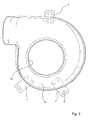
Fig. 3 is a side elevation view of the half-shell of the manifold ofFig. 2 , -
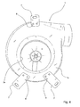
Fig. 4 is another side elevation view of the manifold of the preceding Figures, -
Figs. 5 and 6 are partially sectioned views of a detail of the manifold of the preceding Figures, in separate assembly operations, -
Fig. 7 is a partial view, drawn to an enlarged scale, of another detail of the part illustrated inFigs. 5 and 6 . - With reference to the Figures set out, a scroll type manifold is generally designated 1 and is provided in order to constitute the housing of a radial impeller (not illustrated) of a fan, preferably an electric fan with a relevant electric drive motor.
- The manifold comprises a manifold body, in which there is defined an
intake cross-section 2, which is provided laterally in the manifold, with an intake flow which is substantially coaxial relative to the axis of rotation of the fan and which is schematically indicated X in the Figures, and adelivery cross-section 3, in which the direction of the delivery flow which is indicated by the axis Y in the Figures is directed so as to be substantially perpendicular to the axis X. - The
manifold 1 is also constructed as two half-shells which are designated 1a, 1b, respectively, and which can be connected together in a manner known per se in a connection plane. The half-shells are preferably formed in a practically specularly symmetrical manner with respect to the connection plane, the plane therefore defining a median plane of substantial symmetry. - There is provided in the half-shell la the
intake cross-section 2 of the fan, comprising alateral opening 2a which is coaxial with the axis X of the impeller. - The half-
shells - In order to connect the
manifold 1 to a fixed structure of the boiler, there are provided connection means which are generally designated 5 and described in detail below and which are configured in order to act between a connection surface which is provided in the boiler structure, which is schematically illustrated and designated 6, and theside wall 2b of the manifold having theintake opening 2a. The above-mentioned connection means comprise a plurality of connection extension pieces, all designated 7, which are structurally independent of the manifold and each of which is capable of engaging, at least partially, with arespective seat 8 which is provided in the manifold. - In greater detail, there is provision for the
seats 8 to be formed on the half-shell 1a (having the intake cross-section 2) and for a main portion of the seat to be constructed on theouter side wall 2b of that half-shell. Advantageously, eachseat 8 is produced at the same time during the operation of stamping the half-shell 1a (from sheet metal) and is formed in such a manner as to construct a type of recess, in which at least part of the correspondingconnection extension piece 7 is received, with relevant unidirectional positioning, as illustrated inFig. 4 . In other words, theseat 8 is selected so as to have such dimensions that thecorresponding extension piece 7 is received by means of positioning which is unidirectionally defined with substantial form-fitting. There is further provision for the depth of theseat 8 to be selected in such a manner that theextension piece 7, which is engaged therein, is continuous relative to the outer surface of thewall 2b of the half-shell 1a, as will be appreciated clearly fromFig. 6 . - Each
extension piece 7 is preferably of plate-like form and is constructed from cut or stamped sheet metal and is provided, at the side opposite the end intended for engaging in theseat 8, with one or more through-holes 9, which may or may not be slotted, through which screw type means can be engaged and are intended to fix the manifold to the boiler structure. - Each
connection extension piece 7 is further secured to the manifold in a stable manner by means of punching, that is to say, with one or more punching locations brought about between theextension piece 7 and thewall 2 of the half-shell, in the region of theseat 8.Fig. 7 illustrates, to an enlarged scale, the detail of the punching zone, with which eachextension piece 7 is secured to the half-shell 1a. It will be appreciated that the punching provides for localized deformation so as not to involve any perforation of thewall 2b of the manifold. - It will be understood that other techniques for fixing the
extension pieces 7 in thecorresponding seats 8 are possible, fixing by means of punching constituting a preferred selection. - There is finally provision for the
extension pieces 7 to be provided on the half-shell 1a in relevant numbers and with predetermined relevant positioning so as to ensure suitable support and fixing of the manifold with respect to the boiler structure. The solution described, with three extension pieces being provided, two of which are in a position close together with respect to the third one which is provided near the delivery cross-section, therefore constitutes only one of the possible preferred selections. - The invention thereby achieves the objects set out, involving a number of advantages over known solutions.
- A main advantage consists in that the construction of connection extension pieces of the manifold according to the invention makes using sheet metal stamping for producing the manifold possible and economically justified, for example, as a valid alternative to pressure die-casting, at the same time facilitating the operations for positioning and fixing the connection extension pieces which are intended to allow the manifold to be connected to a structure of the boiler.
Claims (9)
- A scroll type manifold (1), in particular for electric fans which are intended for use in boilers, comprising a manifold body which is constructed from stamped sheet metal and connection means (5) which can be secured to the body in order to connect the manifold to a structure of the boiler, the connection means comprising at least one connection extension piece (7) which is structurally independent of the body of the manifold (1) and at least one respective seat (8) which is formed on the manifold body and which can receive, with relevant unidirectional positioning, the connection extension piece (7), fixing means being provided between the extension piece (7) and the body in order to fixedly join the extension piece to the manifold (1), characterized in that the at least one seat (8) is in the form of a superficial recess which is able to receive at least part of the connection extension piece (7), the dimension of the recess being selected so that the extension piece (7), when it is received in the recess, is substantially continuous relative to the outer surface of the half-shell, in the side wall (2b) thereof, near the intake zone of the fan.
- A scroll type manifold according to claim 1, wherein the at least one seat (8) is formed on the manifold body during the sheet metal stamping operation for constructing the body.
- A manifold according to claim 1 or 2, wherein the manifold body comprises a pair of manifold half-shells (1a, 1b) which can be connected to each other, there being provided on one of the shells a lateral intake opening (2a) of the fan, the at least one connection extension piece (7) being able to be secured to the half-shell (1a) including the intake opening (2a).
- A manifold according to any one of the preceding claims, wherein the at least one extension piece (7) is of plate-like form.
- A manifold according to claim 4, wherein the extension piece has at least one through-hole (9), at the side opposite the region for being received in the corresponding seat (8), for the engagement of screw type connection means which are provided in order to fixedly join the manifold to the boiler structure.
- A manifold according to any one of the preceding claims, wherein the at least one connection piece (7) is fixed to the body of the manifold (1) by means of punching.
- A manifold according to claim 6, wherein the means for fixing the extension piece (7) in the seat (8) comprise one or more punching locations between the extension piece and the manifold, which are provided in the region of the corresponding seat (8).
- A manifold according to claim 7, wherein the punching locations are brought about in such a manner as not to create perforations in the side wall (2b) of the manifold.
- A manifold according to one or more of the preceding claims, wherein there are provided at least three plate-like connection extension pieces (7) of the manifold, each extension piece being provided at the intake side of the manifold.
Priority Applications (1)
| Application Number | Priority Date | Filing Date | Title |
|---|---|---|---|
| PL08804067T PL2191146T3 (en) | 2007-09-28 | 2008-09-11 | Scroll type manifold for fans with an improved system for connection to a boiler structure or the like. |
Applications Claiming Priority (2)
| Application Number | Priority Date | Filing Date | Title |
|---|---|---|---|
| IT000081U ITPD20070081U1 (en) | 2007-09-28 | 2007-09-28 | LINK COLLECTOR FOR FAN WITH REFINED SYSTEM OF CONNECTION TO A BOILER OR SIMILAR STRUCTURE |
| PCT/EP2008/062102 WO2009040257A1 (en) | 2007-09-28 | 2008-09-11 | Scroll type manifold for fans with an improved system for connection to a boiler structure or the like. |
Publications (2)
| Publication Number | Publication Date |
|---|---|
| EP2191146A1 EP2191146A1 (en) | 2010-06-02 |
| EP2191146B1 true EP2191146B1 (en) | 2012-09-26 |
Family
ID=40260672
Family Applications (1)
| Application Number | Title | Priority Date | Filing Date |
|---|---|---|---|
| EP08804067A Active EP2191146B1 (en) | 2007-09-28 | 2008-09-11 | Scroll type manifold for fans with an improved system for connection to a boiler structure or the like. |
Country Status (6)
| Country | Link |
|---|---|
| EP (1) | EP2191146B1 (en) |
| CN (1) | CN102112752A (en) |
| IT (1) | ITPD20070081U1 (en) |
| PL (1) | PL2191146T3 (en) |
| RU (1) | RU2486372C2 (en) |
| WO (1) | WO2009040257A1 (en) |
Families Citing this family (1)
| Publication number | Priority date | Publication date | Assignee | Title |
|---|---|---|---|---|
| CN111306649B (en) * | 2020-03-30 | 2024-11-22 | 广东美的制冷设备有限公司 | Branch box and multi-connected air conditioner |
Family Cites Families (9)
| Publication number | Priority date | Publication date | Assignee | Title |
|---|---|---|---|---|
| DE1898022U (en) * | 1964-03-17 | 1964-08-06 | Heinz Baus | AIR CONDUCTION HOUSING FOR ROLLER SHAPED FANS. |
| FI89201C (en) * | 1991-06-06 | 1993-08-25 | Vallox Oy | FOUNDATION FACTOR |
| JPH07317699A (en) * | 1994-05-23 | 1995-12-05 | Matsushita Electric Ind Co Ltd | Cylindrical multi-blade fan casing |
| CN2279469Y (en) * | 1996-09-04 | 1998-04-22 | 洪美兰 | Nesting combined electric fan base structure |
| CN1335456A (en) * | 2000-08-01 | 2002-02-13 | 汤健中 | Blower hood with angle bar frame |
| CN2517166Y (en) * | 2001-11-22 | 2002-10-16 | 建准电机工业股份有限公司 | Power lead-in device for DC motor |
| US7001149B1 (en) * | 2004-03-04 | 2006-02-21 | Beckett Air Incorporated | Blower housing assembly with mounting tabs |
| JP2006035244A (en) * | 2004-07-23 | 2006-02-09 | Auto Network Gijutsu Kenkyusho:Kk | Cold welding method and metal joined body |
| EP1657451A1 (en) * | 2004-11-12 | 2006-05-17 | Hans Östberg | A duct fan |
-
2007
- 2007-09-28 IT IT000081U patent/ITPD20070081U1/en unknown
-
2008
- 2008-09-11 EP EP08804067A patent/EP2191146B1/en active Active
- 2008-09-11 CN CN2008801091034A patent/CN102112752A/en active Pending
- 2008-09-11 PL PL08804067T patent/PL2191146T3/en unknown
- 2008-09-11 RU RU2010116753/06A patent/RU2486372C2/en active
- 2008-09-11 WO PCT/EP2008/062102 patent/WO2009040257A1/en not_active Ceased
Also Published As
| Publication number | Publication date |
|---|---|
| PL2191146T3 (en) | 2013-04-30 |
| CN102112752A (en) | 2011-06-29 |
| RU2486372C2 (en) | 2013-06-27 |
| WO2009040257A1 (en) | 2009-04-02 |
| ITPD20070081U1 (en) | 2009-03-29 |
| RU2010116753A (en) | 2011-11-10 |
| EP2191146A1 (en) | 2010-06-02 |
Similar Documents
| Publication | Publication Date | Title |
|---|---|---|
| US11624372B2 (en) | Centrifugal blower | |
| US20110103981A1 (en) | Heat Dissipating Fan | |
| CN112901664B (en) | Bearing and bearing seat assembly and mounting structure thereof | |
| JP4278488B2 (en) | Air conditioner outdoor unit | |
| CN215675544U (en) | Wind-guiding circle, air conditioner outdoor unit and air conditioner | |
| EP2191146A1 (en) | Scroll type manifold for fans with an improved system for connection to a boiler structure or the like. | |
| US6761343B2 (en) | Single-piece motor mount | |
| JP4527966B2 (en) | Molecular pump | |
| CN213713491U (en) | Outlet Frame Assembly and Air Conditioner | |
| US7282823B2 (en) | Self-cooling electric machine | |
| CN113091138A (en) | Vertical air conditioner and processing system of air duct structure of vertical air conditioner | |
| EP1967740A2 (en) | A manifold, in particular a scroll type manifold for fans for use in extractor hoods | |
| US20050019159A1 (en) | Blower housing for furnace blower assembly | |
| CN108194392B (en) | Air purifier of low noise | |
| CN112654769A (en) | Covering element for a component of an exhaust system and method for producing such a component with a covering element | |
| JP2006527809A (en) | G-rotor pump | |
| KR101015433B1 (en) | Fixture of Fan Assembly | |
| JP6192035B2 (en) | Pedal device and method for manufacturing pedal device | |
| CN102971540A (en) | Fan module | |
| RU2663970C2 (en) | Diaphragm pump with electric drive and method of its production | |
| CN218407829U (en) | Stable form fire control axial compressor centrifugal fan that discharges fume | |
| CN223648155U (en) | A fan system, a range hood, and an integrated cooktop | |
| CN214125050U (en) | Motor and motor connection structure | |
| JP2000188841A (en) | DC brushless motor | |
| US20260049616A1 (en) | Impellers and manufacturing methods thereof |
Legal Events
| Date | Code | Title | Description |
|---|---|---|---|
| PUAI | Public reference made under article 153(3) epc to a published international application that has entered the european phase |
Free format text: ORIGINAL CODE: 0009012 |
|
| 17P | Request for examination filed |
Effective date: 20100312 |
|
| AK | Designated contracting states |
Kind code of ref document: A1 Designated state(s): AT BE BG CH CY CZ DE DK EE ES FI FR GB GR HR HU IE IS IT LI LT LU LV MC MT NL NO PL PT RO SE SI SK TR |
|
| AX | Request for extension of the european patent |
Extension state: AL BA MK RS |
|
| GRAP | Despatch of communication of intention to grant a patent |
Free format text: ORIGINAL CODE: EPIDOSNIGR1 |
|
| GRAS | Grant fee paid |
Free format text: ORIGINAL CODE: EPIDOSNIGR3 |
|
| GRAA | (expected) grant |
Free format text: ORIGINAL CODE: 0009210 |
|
| AK | Designated contracting states |
Kind code of ref document: B1 Designated state(s): AT BE BG CH CY CZ DE DK EE ES FI FR GB GR HR HU IE IS IT LI LT LU LV MC MT NL NO PL PT RO SE SI SK TR |
|
| AX | Request for extension of the european patent |
Extension state: AL BA MK RS |
|
| REG | Reference to a national code |
Ref country code: GB Ref legal event code: FG4D |
|
| REG | Reference to a national code |
Ref country code: CH Ref legal event code: EP |
|
| REG | Reference to a national code |
Ref country code: AT Ref legal event code: REF Ref document number: 577193 Country of ref document: AT Kind code of ref document: T Effective date: 20121015 |
|
| REG | Reference to a national code |
Ref country code: IE Ref legal event code: FG4D |
|
| REG | Reference to a national code |
Ref country code: DE Ref legal event code: R096 Ref document number: 602008019041 Country of ref document: DE Effective date: 20121122 |
|
| PG25 | Lapsed in a contracting state [announced via postgrant information from national office to epo] |
Ref country code: FI Free format text: LAPSE BECAUSE OF FAILURE TO SUBMIT A TRANSLATION OF THE DESCRIPTION OR TO PAY THE FEE WITHIN THE PRESCRIBED TIME-LIMIT Effective date: 20120926 Ref country code: HR Free format text: LAPSE BECAUSE OF FAILURE TO SUBMIT A TRANSLATION OF THE DESCRIPTION OR TO PAY THE FEE WITHIN THE PRESCRIBED TIME-LIMIT Effective date: 20120926 Ref country code: NO Free format text: LAPSE BECAUSE OF FAILURE TO SUBMIT A TRANSLATION OF THE DESCRIPTION OR TO PAY THE FEE WITHIN THE PRESCRIBED TIME-LIMIT Effective date: 20121226 Ref country code: LT Free format text: LAPSE BECAUSE OF FAILURE TO SUBMIT A TRANSLATION OF THE DESCRIPTION OR TO PAY THE FEE WITHIN THE PRESCRIBED TIME-LIMIT Effective date: 20120926 |
|
| REG | Reference to a national code |
Ref country code: NL Ref legal event code: T3 |
|
| REG | Reference to a national code |
Ref country code: AT Ref legal event code: MK05 Ref document number: 577193 Country of ref document: AT Kind code of ref document: T Effective date: 20120926 |
|
| REG | Reference to a national code |
Ref country code: LT Ref legal event code: MG4D Effective date: 20120926 |
|
| PG25 | Lapsed in a contracting state [announced via postgrant information from national office to epo] |
Ref country code: SI Free format text: LAPSE BECAUSE OF FAILURE TO SUBMIT A TRANSLATION OF THE DESCRIPTION OR TO PAY THE FEE WITHIN THE PRESCRIBED TIME-LIMIT Effective date: 20120926 Ref country code: LV Free format text: LAPSE BECAUSE OF FAILURE TO SUBMIT A TRANSLATION OF THE DESCRIPTION OR TO PAY THE FEE WITHIN THE PRESCRIBED TIME-LIMIT Effective date: 20120926 Ref country code: SE Free format text: LAPSE BECAUSE OF FAILURE TO SUBMIT A TRANSLATION OF THE DESCRIPTION OR TO PAY THE FEE WITHIN THE PRESCRIBED TIME-LIMIT Effective date: 20120926 Ref country code: GR Free format text: LAPSE BECAUSE OF FAILURE TO SUBMIT A TRANSLATION OF THE DESCRIPTION OR TO PAY THE FEE WITHIN THE PRESCRIBED TIME-LIMIT Effective date: 20121227 |
|
| PG25 | Lapsed in a contracting state [announced via postgrant information from national office to epo] |
Ref country code: CZ Free format text: LAPSE BECAUSE OF FAILURE TO SUBMIT A TRANSLATION OF THE DESCRIPTION OR TO PAY THE FEE WITHIN THE PRESCRIBED TIME-LIMIT Effective date: 20120926 Ref country code: EE Free format text: LAPSE BECAUSE OF FAILURE TO SUBMIT A TRANSLATION OF THE DESCRIPTION OR TO PAY THE FEE WITHIN THE PRESCRIBED TIME-LIMIT Effective date: 20120926 Ref country code: IS Free format text: LAPSE BECAUSE OF FAILURE TO SUBMIT A TRANSLATION OF THE DESCRIPTION OR TO PAY THE FEE WITHIN THE PRESCRIBED TIME-LIMIT Effective date: 20130126 Ref country code: RO Free format text: LAPSE BECAUSE OF FAILURE TO SUBMIT A TRANSLATION OF THE DESCRIPTION OR TO PAY THE FEE WITHIN THE PRESCRIBED TIME-LIMIT Effective date: 20120926 Ref country code: BE Free format text: LAPSE BECAUSE OF FAILURE TO SUBMIT A TRANSLATION OF THE DESCRIPTION OR TO PAY THE FEE WITHIN THE PRESCRIBED TIME-LIMIT Effective date: 20120926 Ref country code: ES Free format text: LAPSE BECAUSE OF FAILURE TO SUBMIT A TRANSLATION OF THE DESCRIPTION OR TO PAY THE FEE WITHIN THE PRESCRIBED TIME-LIMIT Effective date: 20130106 |
|
| REG | Reference to a national code |
Ref country code: PL Ref legal event code: T3 |
|
| PG25 | Lapsed in a contracting state [announced via postgrant information from national office to epo] |
Ref country code: SK Free format text: LAPSE BECAUSE OF FAILURE TO SUBMIT A TRANSLATION OF THE DESCRIPTION OR TO PAY THE FEE WITHIN THE PRESCRIBED TIME-LIMIT Effective date: 20120926 Ref country code: PT Free format text: LAPSE BECAUSE OF FAILURE TO SUBMIT A TRANSLATION OF THE DESCRIPTION OR TO PAY THE FEE WITHIN THE PRESCRIBED TIME-LIMIT Effective date: 20130128 |
|
| PG25 | Lapsed in a contracting state [announced via postgrant information from national office to epo] |
Ref country code: AT Free format text: LAPSE BECAUSE OF FAILURE TO SUBMIT A TRANSLATION OF THE DESCRIPTION OR TO PAY THE FEE WITHIN THE PRESCRIBED TIME-LIMIT Effective date: 20120926 |
|
| PG25 | Lapsed in a contracting state [announced via postgrant information from national office to epo] |
Ref country code: DK Free format text: LAPSE BECAUSE OF FAILURE TO SUBMIT A TRANSLATION OF THE DESCRIPTION OR TO PAY THE FEE WITHIN THE PRESCRIBED TIME-LIMIT Effective date: 20120926 Ref country code: BG Free format text: LAPSE BECAUSE OF FAILURE TO SUBMIT A TRANSLATION OF THE DESCRIPTION OR TO PAY THE FEE WITHIN THE PRESCRIBED TIME-LIMIT Effective date: 20121226 |
|
| PLBE | No opposition filed within time limit |
Free format text: ORIGINAL CODE: 0009261 |
|
| STAA | Information on the status of an ep patent application or granted ep patent |
Free format text: STATUS: NO OPPOSITION FILED WITHIN TIME LIMIT |
|
| 26N | No opposition filed |
Effective date: 20130627 |
|
| REG | Reference to a national code |
Ref country code: DE Ref legal event code: R097 Ref document number: 602008019041 Country of ref document: DE Effective date: 20130627 |
|
| PG25 | Lapsed in a contracting state [announced via postgrant information from national office to epo] |
Ref country code: CY Free format text: LAPSE BECAUSE OF FAILURE TO SUBMIT A TRANSLATION OF THE DESCRIPTION OR TO PAY THE FEE WITHIN THE PRESCRIBED TIME-LIMIT Effective date: 20120926 |
|
| PG25 | Lapsed in a contracting state [announced via postgrant information from national office to epo] |
Ref country code: MC Free format text: LAPSE BECAUSE OF FAILURE TO SUBMIT A TRANSLATION OF THE DESCRIPTION OR TO PAY THE FEE WITHIN THE PRESCRIBED TIME-LIMIT Effective date: 20120926 |
|
| REG | Reference to a national code |
Ref country code: CH Ref legal event code: PL |
|
| REG | Reference to a national code |
Ref country code: IE Ref legal event code: MM4A |
|
| PG25 | Lapsed in a contracting state [announced via postgrant information from national office to epo] |
Ref country code: CH Free format text: LAPSE BECAUSE OF NON-PAYMENT OF DUE FEES Effective date: 20130930 Ref country code: LI Free format text: LAPSE BECAUSE OF NON-PAYMENT OF DUE FEES Effective date: 20130930 Ref country code: IE Free format text: LAPSE BECAUSE OF NON-PAYMENT OF DUE FEES Effective date: 20130911 |
|
| REG | Reference to a national code |
Ref country code: DE Ref legal event code: R082 Ref document number: 602008019041 Country of ref document: DE Representative=s name: DREISS PATENTANWAELTE PARTG MBB, DE |
|
| REG | Reference to a national code |
Ref country code: GB Ref legal event code: 732E Free format text: REGISTERED BETWEEN 20150122 AND 20150128 |
|
| REG | Reference to a national code |
Ref country code: DE Ref legal event code: R082 Ref document number: 602008019041 Country of ref document: DE Representative=s name: DREISS PATENTANWAELTE PARTG MBB, DE Effective date: 20150213 Ref country code: DE Ref legal event code: R081 Ref document number: 602008019041 Country of ref document: DE Owner name: SIT S.P.A., IT Free format text: FORMER OWNER: LN 2 S.R.L. A SOCIO UNICO, 62010 MONTECASSIANO, IT Effective date: 20150213 |
|
| REG | Reference to a national code |
Ref country code: FR Ref legal event code: GC Effective date: 20150223 Ref country code: FR Ref legal event code: TP Owner name: SIT S.P.A., IT Effective date: 20150223 |
|
| REG | Reference to a national code |
Ref country code: NL Ref legal event code: SD Effective date: 20150602 Ref country code: NL Ref legal event code: TD Effective date: 20150602 |
|
| PG25 | Lapsed in a contracting state [announced via postgrant information from national office to epo] |
Ref country code: MT Free format text: LAPSE BECAUSE OF FAILURE TO SUBMIT A TRANSLATION OF THE DESCRIPTION OR TO PAY THE FEE WITHIN THE PRESCRIBED TIME-LIMIT Effective date: 20120926 |
|
| PG25 | Lapsed in a contracting state [announced via postgrant information from national office to epo] |
Ref country code: HU Free format text: LAPSE BECAUSE OF FAILURE TO SUBMIT A TRANSLATION OF THE DESCRIPTION OR TO PAY THE FEE WITHIN THE PRESCRIBED TIME-LIMIT; INVALID AB INITIO Effective date: 20080911 Ref country code: LU Free format text: LAPSE BECAUSE OF NON-PAYMENT OF DUE FEES Effective date: 20130911 |
|
| REG | Reference to a national code |
Ref country code: FR Ref legal event code: PLFP Year of fee payment: 9 |
|
| REG | Reference to a national code |
Ref country code: FR Ref legal event code: PLFP Year of fee payment: 10 |
|
| REG | Reference to a national code |
Ref country code: NL Ref legal event code: RF Free format text: RIGHT OF PLEDGE, REMOVED Effective date: 20171121 |
|
| REG | Reference to a national code |
Ref country code: FR Ref legal event code: RG Effective date: 20180202 |
|
| REG | Reference to a national code |
Ref country code: FR Ref legal event code: PLFP Year of fee payment: 11 |
|
| P01 | Opt-out of the competence of the unified patent court (upc) registered |
Effective date: 20230517 |
|
| PGFP | Annual fee paid to national office [announced via postgrant information from national office to epo] |
Ref country code: NL Payment date: 20240820 Year of fee payment: 17 |
|
| PGFP | Annual fee paid to national office [announced via postgrant information from national office to epo] |
Ref country code: DE Payment date: 20240820 Year of fee payment: 17 |
|
| PGFP | Annual fee paid to national office [announced via postgrant information from national office to epo] |
Ref country code: GB Payment date: 20240821 Year of fee payment: 17 |
|
| PGFP | Annual fee paid to national office [announced via postgrant information from national office to epo] |
Ref country code: FR Payment date: 20240820 Year of fee payment: 17 |
|
| PGFP | Annual fee paid to national office [announced via postgrant information from national office to epo] |
Ref country code: PL Payment date: 20240904 Year of fee payment: 17 |
|
| PGFP | Annual fee paid to national office [announced via postgrant information from national office to epo] |
Ref country code: IT Payment date: 20240820 Year of fee payment: 17 |
|
| PGFP | Annual fee paid to national office [announced via postgrant information from national office to epo] |
Ref country code: TR Payment date: 20240828 Year of fee payment: 17 |
|
| REG | Reference to a national code |
Ref country code: NL Ref legal event code: MM Effective date: 20251001 |