EP2191082B1 - Attachment of assembly construction elements - Google Patents
Attachment of assembly construction elements Download PDFInfo
- Publication number
- EP2191082B1 EP2191082B1 EP08794242A EP08794242A EP2191082B1 EP 2191082 B1 EP2191082 B1 EP 2191082B1 EP 08794242 A EP08794242 A EP 08794242A EP 08794242 A EP08794242 A EP 08794242A EP 2191082 B1 EP2191082 B1 EP 2191082B1
- Authority
- EP
- European Patent Office
- Prior art keywords
- assembly
- construction
- attachment
- load carrying
- support element
- Prior art date
- Legal status (The legal status is an assumption and is not a legal conclusion. Google has not performed a legal analysis and makes no representation as to the accuracy of the status listed.)
- Active
Links
- 238000010276 construction Methods 0.000 title claims abstract description 58
- 238000013016 damping Methods 0.000 abstract description 4
- 230000000694 effects Effects 0.000 abstract description 2
- 230000002787 reinforcement Effects 0.000 description 4
- 238000005253 cladding Methods 0.000 description 2
- 239000002184 metal Substances 0.000 description 2
- 230000003068 static effect Effects 0.000 description 2
- 229910000831 Steel Inorganic materials 0.000 description 1
- 238000005516 engineering process Methods 0.000 description 1
- 238000004519 manufacturing process Methods 0.000 description 1
- 230000002035 prolonged effect Effects 0.000 description 1
- 230000035939 shock Effects 0.000 description 1
- 239000010959 steel Substances 0.000 description 1
Images


Classifications
-
- E—FIXED CONSTRUCTIONS
- E04—BUILDING
- E04F—FINISHING WORK ON BUILDINGS, e.g. STAIRS, FLOORS
- E04F13/00—Coverings or linings, e.g. for walls or ceilings
- E04F13/07—Coverings or linings, e.g. for walls or ceilings composed of covering or lining elements; Sub-structures therefor; Fastening means therefor
- E04F13/08—Coverings or linings, e.g. for walls or ceilings composed of covering or lining elements; Sub-structures therefor; Fastening means therefor composed of a plurality of similar covering or lining elements
- E04F13/0801—Separate fastening elements
- E04F13/0803—Separate fastening elements with load-supporting elongated furring elements between wall and covering elements
- E04F13/0805—Separate fastening elements with load-supporting elongated furring elements between wall and covering elements with additional fastening elements between furring elements and the wall
- E04F13/0808—Separate fastening elements with load-supporting elongated furring elements between wall and covering elements with additional fastening elements between furring elements and the wall adjustable in several directions one of which is perpendicular to the wall
Definitions
- Prefabricated construction elements which represent elements of the envelope or internal structure of the buildings are exposed to working of external loads such as wind or temperature difference, said loads transferred to load carrying structure over attaching elements, said attaching elements providing appropriate connectivity on one hand, and provide for appropriate elasticity of attachment on the other side.
- This invention is related to improvement of attaching of structural elements with emphasis on attaching of sandwich panels with metal or other type of envelope with hidden or visible attaching elements.
- Prefabricated construction elements represent element of the envelope or internal structure of the building, and are most commonly manufactured from prefabricated elements of one-layered or sandwich construction, said elements axially and/or transversally composed into construction sections of larger dimensions.
- the construction elements are attached to load carrying structure of steel, concrete or wooden columns or walls using system of attaching elements which are attached in visible or invisible manner with attachment means.
- equalization substructure of load carrying supporting element which are point- or line-wise attached onto the basic load carrying construction (structure) with aid of attachment elements. Due to exposure of prefabricated construction elements to the outside loads which are then transferred to the load carrying structure via attachment element one needs to provide for appropriate connection and because of static and dilatation requirements appropriate elasticity of connection.
- the subject of this invention describes new way of attaching of assembly elements onto the buildings with emphasizing connection of sandwich panels with metal or other type of envelope using hidden or visible connection elements.
- the subject of invention is advanced solution of system of connection of assembly of construction elements in case of multi-field system of assembly providing for partial ability to move elements for static reasons on intermediate supports while providing for simple and fast assembly of elements onto the load carrying construction.
- connection of elements relevant for this invention is further realized using particular form of connecting element with applied elastic layer, said layer connected to assembly scaffolding using attaching bolts or any other type of attachment.
- said layer damping the strokes and alleviate the transfer of sound from assembly construction element onto the load carrying construction.
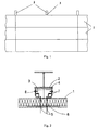
- the assembly construction elements I are transversely connected into the building assembly ( Fig. 1 ).
- the attachment of assembly construction elements is realized using particular form of attachment profile 3 ( Fig. 2 ) with appropriately played elastic layer 7 which is by attachment bolts 5 through reinforcement of assembly construction element 6 attached to assembly construction element 1.
- the attachment profile 3 through elastic layer 7 leans against support element 4 from the inside part on condition that free deformation of assembly element 1 is exceeded.
- attachment profile 3 and support element 4 provide for uniform transfer of loads, provides for good damping of shocks by using built-into elastic layers and reduces the transfer of sound via construction.
- the fundamental advantage of new solution is fast assembly ( Fig. 3 , Fig. 4 ) as pre-assembly of attachment elements using attachment bolts 5 or other types of attachment means is enabled onto the assembly construction element 1 in most suitable construction circumstances - during manufacturing or on ground floor of the construction site rather than on assembly position of construction element as usual with other solutions.
- the attachment profile 3 which is already placed on the assembly construction element 1 can be due to particularly formed cut-outs on support element 4 ( Fig. 5 ) easily put into inside of the support element 4 ( Fig. 3 ., Fig. 4 ) and then the assembly construction element can be put using system of attachment of construction elements into final position, this action easily achievable because of free-play between assembly element 1 and outer surface of support element 4 and attachment profile 3 and inner surface of support element 4.
- the assembly construction elements 1 can be inter-assembled in axial or transversal direction, or combined between axial and transversal assembly. At the same time the number of intermediate supports and/or load carrying constructions can be optional and does not limit the essence of this invention.
Landscapes
- Engineering & Computer Science (AREA)
- Architecture (AREA)
- Civil Engineering (AREA)
- Structural Engineering (AREA)
- Buildings Adapted To Withstand Abnormal External Influences (AREA)
- Finishing Walls (AREA)
- Joining Of Building Structures In Genera (AREA)
Abstract
Description
- Attaching of prefabricated construction elements, connecting of sandwich panels, attaching elements.
- Prefabricated construction elements which represent elements of the envelope or internal structure of the buildings are exposed to working of external loads such as wind or temperature difference, said loads transferred to load carrying structure over attaching elements, said attaching elements providing appropriate connectivity on one hand, and provide for appropriate elasticity of attachment on the other side.
- This invention is related to improvement of attaching of structural elements with emphasis on attaching of sandwich panels with metal or other type of envelope with hidden or visible attaching elements.
- Prefabricated construction elements represent element of the envelope or internal structure of the building, and are most commonly manufactured from prefabricated elements of one-layered or sandwich construction, said elements axially and/or transversally composed into construction sections of larger dimensions. The construction elements are attached to load carrying structure of steel, concrete or wooden columns or walls using system of attaching elements which are attached in visible or invisible manner with attachment means. For equalization of deviations one can use equalization substructure of load carrying supporting element which are point- or line-wise attached onto the basic load carrying construction (structure) with aid of attachment elements. Due to exposure of prefabricated construction elements to the outside loads which are then transferred to the load carrying structure via attachment element one needs to provide for appropriate connection and because of static and dilatation requirements appropriate elasticity of connection.
- There are several patents describing general background of the invention, none of which actually solves the technical problem at hand:
- Patent application
WO98/10151 A - Patent
DE 17 99 420 U describes setup for attachment of panel-like walls to firmly standing walls - Patent application
DE 35 05 335 A1 describes covering of the walls for noise reduction for use in various types of industrial establishments. - Patent
DE 86 16 775 U1 describes covering of walls constructed of flat rear ventilated panels - Patent
DE 296 19 956 U1 describes setup for attachment of profiles, in particular for masonry, wall, bottom or deck coverings or bookshelves attachment with attaching elements connected to the profiles. - Available solutions to the problem of attaching provide for partially movable attachment of assembly element on intermediate supports, however the system of attaching causes ex-centre and shocking loads of assembly construction elements and load carrying construction, and results in prolonged and complicated assembly.
- The subject of this invention describes new way of attaching of assembly elements onto the buildings with emphasizing connection of sandwich panels with metal or other type of envelope using hidden or visible connection elements.
- The subject of invention is advanced solution of system of connection of assembly of construction elements in case of multi-field system of assembly providing for partial ability to move elements for static reasons on intermediate supports while providing for simple and fast assembly of elements onto the load carrying construction.
- The described problems are solved by an assembly according to
claim 1. - The solution of connection of elements relevant for this invention is further realized using particular form of connecting element with applied elastic layer, said layer connected to assembly scaffolding using attaching bolts or any other type of attachment. In case of wind force or temperature difference directed against load carrying construction the assembly construction element leans on support element onto which the elastic layer is applied, said layer damping the strokes and alleviate the transfer of sound from assembly construction element onto the load carrying construction. In case of wind activity or temperature difference in direction from the load carrying construction the attaching profile over elastic layer leans onto the support element from the inner side on condition that free deformation of assembly element is exceeded.
- Below the essence of the invention is described in detail describing embodiments and attached figures, said figures forming part of this patent application, and presenting:
-
Fig. 1 showsassembly construction element 1,load carrying construction 2,attachment profile 3. -
Fig. 2 showsassembly construction element 1,load carrying construction 2,attachment profile 3,support element 4,attachment bolt 5, reinforcement ofassembly construction element 6,elastic layer 7,attachment element 8. -
Fig. 3 showsassembly construction element 1,load carrying construction 2,attachment profile 3,support element 4,attachment bolt 5, reinforcement ofassembly construction element 6. -
Fig. 4 showsassembly construction element 1,load carrying construction 2,attachment profile 3,attachment bolt 5, reinforcement ofassembly construction element 6. -
Fig. 5 showsload carrying construction 2,support element 4,attachment element 8. - In embodiment shown in the figures the assembly construction elements I are transversely connected into the building assembly (
Fig. 1 ). The attachment of assembly construction elements is realized using particular form of attachment profile 3 (Fig. 2 ) with appropriately playedelastic layer 7 which is byattachment bolts 5 through reinforcement ofassembly construction element 6 attached toassembly construction element 1. In case of wind force or temperature difference operating in direction against load carrying construction theassembly building element 1 leans againstsupport element 4, saidsupport element 4 carryingelastic layer 7, said layer damping the strokes and alleviating the transfer of sound fromassembly element 1 viasupport element 4 onto theload carrying construction 2. In case of wind or temperature difference in direction from theload carrying construction 2 theattachment profile 3 throughelastic layer 7 leans againstsupport element 4 from the inside part on condition that free deformation ofassembly element 1 is exceeded. - The solution shown (
Fig. 3 ) due to symmetric construction ofattachment profile 3 andsupport element 4 provides for uniform transfer of loads, provides for good damping of shocks by using built-into elastic layers and reduces the transfer of sound via construction. - The fundamental advantage of new solution is fast assembly (
Fig. 3 ,Fig. 4 ) as pre-assembly of attachment elements usingattachment bolts 5 or other types of attachment means is enabled onto theassembly construction element 1 in most suitable construction circumstances - during manufacturing or on ground floor of the construction site rather than on assembly position of construction element as usual with other solutions. Theattachment profile 3 which is already placed on theassembly construction element 1 can be due to particularly formed cut-outs on support element 4 (Fig. 5 ) easily put into inside of the support element 4 (Fig. 3 .,Fig. 4 ) and then the assembly construction element can be put using system of attachment of construction elements into final position, this action easily achievable because of free-play betweenassembly element 1 and outer surface ofsupport element 4 andattachment profile 3 and inner surface ofsupport element 4. - The
assembly construction elements 1 can be inter-assembled in axial or transversal direction, or combined between axial and transversal assembly. At the same time the number of intermediate supports and/or load carrying constructions can be optional and does not limit the essence of this invention. - The embodiment shown in the figures is implemented provided that internal conformity exists, said conformity meaning that support
element 4 embraces theattachment profile 3 from the outside. - It is self evident that the described invention can be implemented in different embodiments within the scope of the appended claims.
Claims (3)
- Assembly comprising an assembly construction (1) element and attachment elements comprising an attachment profile (3) with applied elastic layer (7) attached onto said assembly construction element (1), further comprising a support element (4) attachable to a load carrying construction (2) characterized in that said attachment profile (3) is placed on the assembly construction element (1) and is due to particularly made cut-outs on the support element (4) placed inside said support element (4).
- The assembly according to claim 1 wherein there is a free-play the between assembly construction element (1) and the outside surface of the support element (4), and also between the attachment profile (3) and the inner surface of support element (4).
- The assembly according to claims 1 or 2 wherein the attachment of elements is implemented by providing of internal conformity, said internal conformity meaning that the support element (4) embraces the attachment profile (3) from the outside.
Applications Claiming Priority (2)
| Application Number | Priority Date | Filing Date | Title |
|---|---|---|---|
| SI200700232A SI22633B (en) | 2007-09-24 | 2007-09-24 | Fastening of prefabricated building elements |
| PCT/SI2008/000048 WO2009041921A1 (en) | 2007-09-24 | 2008-09-11 | Attachment of assembly construction elements |
Publications (2)
| Publication Number | Publication Date |
|---|---|
| EP2191082A1 EP2191082A1 (en) | 2010-06-02 |
| EP2191082B1 true EP2191082B1 (en) | 2012-04-04 |
Family
ID=40085639
Family Applications (1)
| Application Number | Title | Priority Date | Filing Date |
|---|---|---|---|
| EP08794242A Active EP2191082B1 (en) | 2007-09-24 | 2008-09-11 | Attachment of assembly construction elements |
Country Status (5)
| Country | Link |
|---|---|
| EP (1) | EP2191082B1 (en) |
| AT (1) | ATE552393T1 (en) |
| DK (1) | DK2191082T3 (en) |
| SI (1) | SI22633B (en) |
| WO (1) | WO2009041921A1 (en) |
Family Cites Families (5)
| Publication number | Priority date | Publication date | Assignee | Title |
|---|---|---|---|---|
| DE1799420U (en) * | 1959-07-18 | 1959-11-05 | Werner Dr Ing Piening | DEVICE FOR FASTENING BOWL-LIKE WALLS TO FIXED WALLS. |
| DE3505335C2 (en) * | 1985-02-15 | 1996-01-18 | Gruenzweig & Hartmann Montage | Wall cladding |
| DE8616775U1 (en) * | 1986-06-24 | 1986-11-13 | Straub, Theodor, 8857 Wertingen | Facade cladding made of ventilated shell-shaped facade elements |
| AUPO215996A0 (en) * | 1996-09-05 | 1996-10-03 | James Hardie International Finance B.V. | An improved cladding board mounting system |
| DE29619956U1 (en) * | 1996-11-16 | 1997-12-11 | Erl, Klaus, 33330 Gütersloh | Device for fastening profiles |
-
2007
- 2007-09-24 SI SI200700232A patent/SI22633B/en not_active IP Right Cessation
-
2008
- 2008-09-11 AT AT08794242T patent/ATE552393T1/en active
- 2008-09-11 WO PCT/SI2008/000048 patent/WO2009041921A1/en not_active Ceased
- 2008-09-11 DK DK08794242.1T patent/DK2191082T3/en active
- 2008-09-11 EP EP08794242A patent/EP2191082B1/en active Active
Also Published As
| Publication number | Publication date |
|---|---|
| SI22633A (en) | 2009-04-30 |
| DK2191082T3 (en) | 2012-07-09 |
| WO2009041921A1 (en) | 2009-04-02 |
| EP2191082A1 (en) | 2010-06-02 |
| SI22633B (en) | 2013-02-28 |
| ATE552393T1 (en) | 2012-04-15 |
Similar Documents
| Publication | Publication Date | Title |
|---|---|---|
| AU715517B2 (en) | Structural bracing for buildings | |
| KR200438474Y1 (en) | Window frame fixing bracket | |
| KR101129086B1 (en) | Curtain wall system | |
| KR19990053902A (en) | Steel house floor slab damping structure | |
| NO321815B1 (en) | wall Element | |
| CN213837023U (en) | Semi-rigid column base connecting joint structure of wood frame column | |
| CN217480515U (en) | Anti-seismic reinforcing structure for building wall | |
| CN210263610U (en) | Prefabricated wallboard structure keeps warm | |
| EP2672038A3 (en) | A building seismic strengthening system | |
| WO2009041921A1 (en) | Attachment of assembly construction elements | |
| CN104088384A (en) | Composite GRC curtain wall | |
| JP4189817B2 (en) | Unit building | |
| KR101740550B1 (en) | curtain wall of insulation Composite | |
| JP3673517B2 (en) | Building wall structure | |
| JPH06136877A (en) | Structural material for architecture | |
| CN215565002U (en) | Wall structure made of microlite plates | |
| KR20050090167A (en) | Noise interception sturcture of apartment of storey | |
| JP6096659B2 (en) | Wooden frame building | |
| JP3883076B2 (en) | Seismic reinforcement device that makes use of existing buildings | |
| JP3237960U (en) | Friction vibration control mechanism for wooden houses | |
| CN213296855U (en) | Composite board for interior decoration | |
| CN201952893U (en) | Diagonal bracing conversion device for bottom frame columns of multi-story or high-rise building | |
| JP3033281U (en) | Building reinforced structure | |
| CN115012690A (en) | Reinforcing component on existing building and using method thereof | |
| JP3136745U (en) | Seismic reinforcement walls for wooden houses |
Legal Events
| Date | Code | Title | Description |
|---|---|---|---|
| PUAI | Public reference made under article 153(3) epc to a published international application that has entered the european phase |
Free format text: ORIGINAL CODE: 0009012 |
|
| 17P | Request for examination filed |
Effective date: 20100313 |
|
| AK | Designated contracting states |
Kind code of ref document: A1 Designated state(s): AT BE BG CH CY CZ DE DK EE ES FI FR GB GR HR HU IE IS IT LI LT LU LV MC MT NL NO PL PT RO SE SI SK TR |
|
| AX | Request for extension of the european patent |
Extension state: AL BA MK RS |
|
| 17Q | First examination report despatched |
Effective date: 20110927 |
|
| GRAP | Despatch of communication of intention to grant a patent |
Free format text: ORIGINAL CODE: EPIDOSNIGR1 |
|
| GRAS | Grant fee paid |
Free format text: ORIGINAL CODE: EPIDOSNIGR3 |
|
| GRAA | (expected) grant |
Free format text: ORIGINAL CODE: 0009210 |
|
| AK | Designated contracting states |
Kind code of ref document: B1 Designated state(s): AT BE BG CH CY CZ DE DK EE ES FI FR GB GR HR HU IE IS IT LI LT LU LV MC MT NL NO PL PT RO SE SI SK TR |
|
| AX | Request for extension of the european patent |
Extension state: AL BA MK RS |
|
| REG | Reference to a national code |
Ref country code: GB Ref legal event code: FG4D |
|
| REG | Reference to a national code |
Ref country code: CH Ref legal event code: EP |
|
| REG | Reference to a national code |
Ref country code: AT Ref legal event code: REF Ref document number: 552393 Country of ref document: AT Kind code of ref document: T Effective date: 20120415 |
|
| REG | Reference to a national code |
Ref country code: IE Ref legal event code: FG4D |
|
| REG | Reference to a national code |
Ref country code: DE Ref legal event code: R096 Ref document number: 602008014637 Country of ref document: DE Effective date: 20120531 |
|
| REG | Reference to a national code |
Ref country code: NL Ref legal event code: T3 |
|
| REG | Reference to a national code |
Ref country code: DK Ref legal event code: T3 |
|
| REG | Reference to a national code |
Ref country code: SE Ref legal event code: TRGR |
|
| REG | Reference to a national code |
Ref country code: AT Ref legal event code: MK05 Ref document number: 552393 Country of ref document: AT Kind code of ref document: T Effective date: 20120404 |
|
| LTIE | Lt: invalidation of european patent or patent extension |
Effective date: 20120404 |
|
| PG25 | Lapsed in a contracting state [announced via postgrant information from national office to epo] |
Ref country code: SI Free format text: LAPSE BECAUSE OF FAILURE TO SUBMIT A TRANSLATION OF THE DESCRIPTION OR TO PAY THE FEE WITHIN THE PRESCRIBED TIME-LIMIT Effective date: 20120404 Ref country code: LT Free format text: LAPSE BECAUSE OF FAILURE TO SUBMIT A TRANSLATION OF THE DESCRIPTION OR TO PAY THE FEE WITHIN THE PRESCRIBED TIME-LIMIT Effective date: 20120404 Ref country code: FI Free format text: LAPSE BECAUSE OF FAILURE TO SUBMIT A TRANSLATION OF THE DESCRIPTION OR TO PAY THE FEE WITHIN THE PRESCRIBED TIME-LIMIT Effective date: 20120404 Ref country code: IS Free format text: LAPSE BECAUSE OF FAILURE TO SUBMIT A TRANSLATION OF THE DESCRIPTION OR TO PAY THE FEE WITHIN THE PRESCRIBED TIME-LIMIT Effective date: 20120804 Ref country code: PL Free format text: LAPSE BECAUSE OF FAILURE TO SUBMIT A TRANSLATION OF THE DESCRIPTION OR TO PAY THE FEE WITHIN THE PRESCRIBED TIME-LIMIT Effective date: 20120404 Ref country code: CY Free format text: LAPSE BECAUSE OF FAILURE TO SUBMIT A TRANSLATION OF THE DESCRIPTION OR TO PAY THE FEE WITHIN THE PRESCRIBED TIME-LIMIT Effective date: 20120404 Ref country code: NO Free format text: LAPSE BECAUSE OF FAILURE TO SUBMIT A TRANSLATION OF THE DESCRIPTION OR TO PAY THE FEE WITHIN THE PRESCRIBED TIME-LIMIT Effective date: 20120704 |
|
| PG25 | Lapsed in a contracting state [announced via postgrant information from national office to epo] |
Ref country code: GR Free format text: LAPSE BECAUSE OF FAILURE TO SUBMIT A TRANSLATION OF THE DESCRIPTION OR TO PAY THE FEE WITHIN THE PRESCRIBED TIME-LIMIT Effective date: 20120705 Ref country code: HR Free format text: LAPSE BECAUSE OF FAILURE TO SUBMIT A TRANSLATION OF THE DESCRIPTION OR TO PAY THE FEE WITHIN THE PRESCRIBED TIME-LIMIT Effective date: 20120404 Ref country code: PT Free format text: LAPSE BECAUSE OF FAILURE TO SUBMIT A TRANSLATION OF THE DESCRIPTION OR TO PAY THE FEE WITHIN THE PRESCRIBED TIME-LIMIT Effective date: 20120806 Ref country code: LV Free format text: LAPSE BECAUSE OF FAILURE TO SUBMIT A TRANSLATION OF THE DESCRIPTION OR TO PAY THE FEE WITHIN THE PRESCRIBED TIME-LIMIT Effective date: 20120404 |
|
| PG25 | Lapsed in a contracting state [announced via postgrant information from national office to epo] |
Ref country code: BE Free format text: LAPSE BECAUSE OF FAILURE TO SUBMIT A TRANSLATION OF THE DESCRIPTION OR TO PAY THE FEE WITHIN THE PRESCRIBED TIME-LIMIT Effective date: 20120404 |
|
| PG25 | Lapsed in a contracting state [announced via postgrant information from national office to epo] |
Ref country code: AT Free format text: LAPSE BECAUSE OF FAILURE TO SUBMIT A TRANSLATION OF THE DESCRIPTION OR TO PAY THE FEE WITHIN THE PRESCRIBED TIME-LIMIT Effective date: 20120404 Ref country code: CZ Free format text: LAPSE BECAUSE OF FAILURE TO SUBMIT A TRANSLATION OF THE DESCRIPTION OR TO PAY THE FEE WITHIN THE PRESCRIBED TIME-LIMIT Effective date: 20120404 Ref country code: EE Free format text: LAPSE BECAUSE OF FAILURE TO SUBMIT A TRANSLATION OF THE DESCRIPTION OR TO PAY THE FEE WITHIN THE PRESCRIBED TIME-LIMIT Effective date: 20120404 Ref country code: RO Free format text: LAPSE BECAUSE OF FAILURE TO SUBMIT A TRANSLATION OF THE DESCRIPTION OR TO PAY THE FEE WITHIN THE PRESCRIBED TIME-LIMIT Effective date: 20120404 Ref country code: SK Free format text: LAPSE BECAUSE OF FAILURE TO SUBMIT A TRANSLATION OF THE DESCRIPTION OR TO PAY THE FEE WITHIN THE PRESCRIBED TIME-LIMIT Effective date: 20120404 |
|
| PLBE | No opposition filed within time limit |
Free format text: ORIGINAL CODE: 0009261 |
|
| STAA | Information on the status of an ep patent application or granted ep patent |
Free format text: STATUS: NO OPPOSITION FILED WITHIN TIME LIMIT |
|
| PG25 | Lapsed in a contracting state [announced via postgrant information from national office to epo] |
Ref country code: IT Free format text: LAPSE BECAUSE OF FAILURE TO SUBMIT A TRANSLATION OF THE DESCRIPTION OR TO PAY THE FEE WITHIN THE PRESCRIBED TIME-LIMIT Effective date: 20120404 |
|
| 26N | No opposition filed |
Effective date: 20130107 |
|
| PG25 | Lapsed in a contracting state [announced via postgrant information from national office to epo] |
Ref country code: ES Free format text: LAPSE BECAUSE OF FAILURE TO SUBMIT A TRANSLATION OF THE DESCRIPTION OR TO PAY THE FEE WITHIN THE PRESCRIBED TIME-LIMIT Effective date: 20120715 Ref country code: MC Free format text: LAPSE BECAUSE OF NON-PAYMENT OF DUE FEES Effective date: 20120930 |
|
| REG | Reference to a national code |
Ref country code: CH Ref legal event code: PL |
|
| REG | Reference to a national code |
Ref country code: DE Ref legal event code: R097 Ref document number: 602008014637 Country of ref document: DE Effective date: 20130107 |
|
| REG | Reference to a national code |
Ref country code: IE Ref legal event code: MM4A |
|
| REG | Reference to a national code |
Ref country code: FR Ref legal event code: ST Effective date: 20130531 |
|
| PG25 | Lapsed in a contracting state [announced via postgrant information from national office to epo] |
Ref country code: LI Free format text: LAPSE BECAUSE OF NON-PAYMENT OF DUE FEES Effective date: 20120930 Ref country code: BG Free format text: LAPSE BECAUSE OF FAILURE TO SUBMIT A TRANSLATION OF THE DESCRIPTION OR TO PAY THE FEE WITHIN THE PRESCRIBED TIME-LIMIT Effective date: 20120704 Ref country code: IE Free format text: LAPSE BECAUSE OF NON-PAYMENT OF DUE FEES Effective date: 20120911 Ref country code: CH Free format text: LAPSE BECAUSE OF NON-PAYMENT OF DUE FEES Effective date: 20120930 |
|
| PG25 | Lapsed in a contracting state [announced via postgrant information from national office to epo] |
Ref country code: FR Free format text: LAPSE BECAUSE OF NON-PAYMENT OF DUE FEES Effective date: 20121001 |
|
| PGFP | Annual fee paid to national office [announced via postgrant information from national office to epo] |
Ref country code: DK Payment date: 20130925 Year of fee payment: 6 Ref country code: NL Payment date: 20130919 Year of fee payment: 6 Ref country code: SE Payment date: 20130925 Year of fee payment: 6 |
|
| PG25 | Lapsed in a contracting state [announced via postgrant information from national office to epo] |
Ref country code: MT Free format text: LAPSE BECAUSE OF FAILURE TO SUBMIT A TRANSLATION OF THE DESCRIPTION OR TO PAY THE FEE WITHIN THE PRESCRIBED TIME-LIMIT Effective date: 20120404 |
|
| PGFP | Annual fee paid to national office [announced via postgrant information from national office to epo] |
Ref country code: GB Payment date: 20130925 Year of fee payment: 6 |
|
| PGFP | Annual fee paid to national office [announced via postgrant information from national office to epo] |
Ref country code: DE Payment date: 20130930 Year of fee payment: 6 |
|
| PG25 | Lapsed in a contracting state [announced via postgrant information from national office to epo] |
Ref country code: TR Free format text: LAPSE BECAUSE OF FAILURE TO SUBMIT A TRANSLATION OF THE DESCRIPTION OR TO PAY THE FEE WITHIN THE PRESCRIBED TIME-LIMIT Effective date: 20120404 |
|
| PG25 | Lapsed in a contracting state [announced via postgrant information from national office to epo] |
Ref country code: LU Free format text: LAPSE BECAUSE OF NON-PAYMENT OF DUE FEES Effective date: 20120911 |
|
| PG25 | Lapsed in a contracting state [announced via postgrant information from national office to epo] |
Ref country code: HU Free format text: LAPSE BECAUSE OF FAILURE TO SUBMIT A TRANSLATION OF THE DESCRIPTION OR TO PAY THE FEE WITHIN THE PRESCRIBED TIME-LIMIT Effective date: 20080911 |
|
| REG | Reference to a national code |
Ref country code: DE Ref legal event code: R119 Ref document number: 602008014637 Country of ref document: DE |
|
| REG | Reference to a national code |
Ref country code: DK Ref legal event code: EBP Effective date: 20140930 |
|
| REG | Reference to a national code |
Ref country code: SE Ref legal event code: EUG |
|
| GBPC | Gb: european patent ceased through non-payment of renewal fee |
Effective date: 20140911 |
|
| PG25 | Lapsed in a contracting state [announced via postgrant information from national office to epo] |
Ref country code: SE Free format text: LAPSE BECAUSE OF NON-PAYMENT OF DUE FEES Effective date: 20140912 |
|
| REG | Reference to a national code |
Ref country code: DE Ref legal event code: R119 Ref document number: 602008014637 Country of ref document: DE Effective date: 20150401 |
|
| PG25 | Lapsed in a contracting state [announced via postgrant information from national office to epo] |
Ref country code: NL Free format text: LAPSE BECAUSE OF NON-PAYMENT OF DUE FEES Effective date: 20150401 |
|
| PG25 | Lapsed in a contracting state [announced via postgrant information from national office to epo] |
Ref country code: GB Free format text: LAPSE BECAUSE OF NON-PAYMENT OF DUE FEES Effective date: 20140911 Ref country code: DE Free format text: LAPSE BECAUSE OF NON-PAYMENT OF DUE FEES Effective date: 20150401 |
|
| PG25 | Lapsed in a contracting state [announced via postgrant information from national office to epo] |
Ref country code: DK Free format text: LAPSE BECAUSE OF NON-PAYMENT OF DUE FEES Effective date: 20140930 |