EP2190744B1 - Load indicator and method for detecting a hard landing or an overload force during towing of an aircraft - Google Patents
Load indicator and method for detecting a hard landing or an overload force during towing of an aircraft Download PDFInfo
- Publication number
- EP2190744B1 EP2190744B1 EP08806342A EP08806342A EP2190744B1 EP 2190744 B1 EP2190744 B1 EP 2190744B1 EP 08806342 A EP08806342 A EP 08806342A EP 08806342 A EP08806342 A EP 08806342A EP 2190744 B1 EP2190744 B1 EP 2190744B1
- Authority
- EP
- European Patent Office
- Prior art keywords
- load
- indicator
- load bearing
- bearing member
- cavity
- Prior art date
- Legal status (The legal status is an assumption and is not a legal conclusion. Google has not performed a legal analysis and makes no representation as to the accuracy of the status listed.)
- Active
Links
Images


Classifications
-
- F—MECHANICAL ENGINEERING; LIGHTING; HEATING; WEAPONS; BLASTING
- F16—ENGINEERING ELEMENTS AND UNITS; GENERAL MEASURES FOR PRODUCING AND MAINTAINING EFFECTIVE FUNCTIONING OF MACHINES OR INSTALLATIONS; THERMAL INSULATION IN GENERAL
- F16C—SHAFTS; FLEXIBLE SHAFTS; ELEMENTS OR CRANKSHAFT MECHANISMS; ROTARY BODIES OTHER THAN GEARING ELEMENTS; BEARINGS
- F16C23/00—Bearings for exclusively rotary movement adjustable for aligning or positioning
- F16C23/02—Sliding-contact bearings
- F16C23/04—Sliding-contact bearings self-adjusting
- F16C23/043—Sliding-contact bearings self-adjusting with spherical surfaces, e.g. spherical plain bearings
- F16C23/045—Sliding-contact bearings self-adjusting with spherical surfaces, e.g. spherical plain bearings for radial load mainly, e.g. radial spherical plain bearings
-
- B—PERFORMING OPERATIONS; TRANSPORTING
- B64—AIRCRAFT; AVIATION; COSMONAUTICS
- B64F—GROUND OR AIRCRAFT-CARRIER-DECK INSTALLATIONS SPECIALLY ADAPTED FOR USE IN CONNECTION WITH AIRCRAFT; DESIGNING, MANUFACTURING, ASSEMBLING, CLEANING, MAINTAINING OR REPAIRING AIRCRAFT, NOT OTHERWISE PROVIDED FOR; HANDLING, TRANSPORTING, TESTING OR INSPECTING AIRCRAFT COMPONENTS, NOT OTHERWISE PROVIDED FOR
- B64F5/00—Designing, manufacturing, assembling, cleaning, maintaining or repairing aircraft, not otherwise provided for; Handling, transporting, testing or inspecting aircraft components, not otherwise provided for
- B64F5/60—Testing or inspecting aircraft components or systems
-
- B—PERFORMING OPERATIONS; TRANSPORTING
- B64—AIRCRAFT; AVIATION; COSMONAUTICS
- B64C—AEROPLANES; HELICOPTERS
- B64C25/00—Alighting gear
-
- B—PERFORMING OPERATIONS; TRANSPORTING
- B64—AIRCRAFT; AVIATION; COSMONAUTICS
- B64C—AEROPLANES; HELICOPTERS
- B64C25/00—Alighting gear
- B64C25/02—Undercarriages
-
- B—PERFORMING OPERATIONS; TRANSPORTING
- B64—AIRCRAFT; AVIATION; COSMONAUTICS
- B64D—EQUIPMENT FOR FITTING IN OR TO AIRCRAFT; FLIGHT SUITS; PARACHUTES; ARRANGEMENT OR MOUNTING OF POWER PLANTS OR PROPULSION TRANSMISSIONS IN AIRCRAFT
- B64D45/00—Aircraft indicators or protectors not otherwise provided for
-
- F—MECHANICAL ENGINEERING; LIGHTING; HEATING; WEAPONS; BLASTING
- F16—ENGINEERING ELEMENTS AND UNITS; GENERAL MEASURES FOR PRODUCING AND MAINTAINING EFFECTIVE FUNCTIONING OF MACHINES OR INSTALLATIONS; THERMAL INSULATION IN GENERAL
- F16C—SHAFTS; FLEXIBLE SHAFTS; ELEMENTS OR CRANKSHAFT MECHANISMS; ROTARY BODIES OTHER THAN GEARING ELEMENTS; BEARINGS
- F16C11/00—Pivots; Pivotal connections
- F16C11/04—Pivotal connections
- F16C11/045—Pivotal connections with at least a pair of arms pivoting relatively to at least one other arm, all arms being mounted on one pin
-
- F—MECHANICAL ENGINEERING; LIGHTING; HEATING; WEAPONS; BLASTING
- F16—ENGINEERING ELEMENTS AND UNITS; GENERAL MEASURES FOR PRODUCING AND MAINTAINING EFFECTIVE FUNCTIONING OF MACHINES OR INSTALLATIONS; THERMAL INSULATION IN GENERAL
- F16C—SHAFTS; FLEXIBLE SHAFTS; ELEMENTS OR CRANKSHAFT MECHANISMS; ROTARY BODIES OTHER THAN GEARING ELEMENTS; BEARINGS
- F16C17/00—Sliding-contact bearings for exclusively rotary movement
- F16C17/12—Sliding-contact bearings for exclusively rotary movement characterised by features not related to the direction of the load
- F16C17/24—Sliding-contact bearings for exclusively rotary movement characterised by features not related to the direction of the load with devices affected by abnormal or undesired positions, e.g. for preventing overheating, for safety
-
- F—MECHANICAL ENGINEERING; LIGHTING; HEATING; WEAPONS; BLASTING
- F16—ENGINEERING ELEMENTS AND UNITS; GENERAL MEASURES FOR PRODUCING AND MAINTAINING EFFECTIVE FUNCTIONING OF MACHINES OR INSTALLATIONS; THERMAL INSULATION IN GENERAL
- F16C—SHAFTS; FLEXIBLE SHAFTS; ELEMENTS OR CRANKSHAFT MECHANISMS; ROTARY BODIES OTHER THAN GEARING ELEMENTS; BEARINGS
- F16C23/00—Bearings for exclusively rotary movement adjustable for aligning or positioning
- F16C23/02—Sliding-contact bearings
- F16C23/04—Sliding-contact bearings self-adjusting
-
- G—PHYSICS
- G01—MEASURING; TESTING
- G01L—MEASURING FORCE, STRESS, TORQUE, WORK, MECHANICAL POWER, MECHANICAL EFFICIENCY, OR FLUID PRESSURE
- G01L5/00—Apparatus for, or methods of, measuring force, work, mechanical power, or torque, specially adapted for specific purposes
- G01L5/0061—Force sensors associated with industrial machines or actuators
- G01L5/0071—Specific indicating arrangements, e.g. of overload
-
- G—PHYSICS
- G01—MEASURING; TESTING
- G01N—INVESTIGATING OR ANALYSING MATERIALS BY DETERMINING THEIR CHEMICAL OR PHYSICAL PROPERTIES
- G01N19/00—Investigating materials by mechanical methods
- G01N19/08—Detecting presence of flaws or irregularities
-
- G—PHYSICS
- G01—MEASURING; TESTING
- G01N—INVESTIGATING OR ANALYSING MATERIALS BY DETERMINING THEIR CHEMICAL OR PHYSICAL PROPERTIES
- G01N21/00—Investigating or analysing materials by the use of optical means, i.e. using sub-millimetre waves, infrared, visible or ultraviolet light
- G01N21/84—Systems specially adapted for particular applications
- G01N21/88—Investigating the presence of flaws or contamination
- G01N21/8803—Visual inspection
-
- G—PHYSICS
- G01—MEASURING; TESTING
- G01P—MEASURING LINEAR OR ANGULAR SPEED, ACCELERATION, DECELERATION, OR SHOCK; INDICATING PRESENCE, ABSENCE, OR DIRECTION, OF MOVEMENT
- G01P15/00—Measuring acceleration; Measuring deceleration; Measuring shock, i.e. sudden change of acceleration
- G01P15/02—Measuring acceleration; Measuring deceleration; Measuring shock, i.e. sudden change of acceleration by making use of inertia forces using solid seismic masses
- G01P15/04—Measuring acceleration; Measuring deceleration; Measuring shock, i.e. sudden change of acceleration by making use of inertia forces using solid seismic masses for indicating maximum value
- G01P15/06—Measuring acceleration; Measuring deceleration; Measuring shock, i.e. sudden change of acceleration by making use of inertia forces using solid seismic masses for indicating maximum value using members subjected to a permanent deformation
-
- G—PHYSICS
- G08—SIGNALLING
- G08B—SIGNALLING SYSTEMS, e.g. PERSONAL CALLING SYSTEMS; ORDER TELEGRAPHS; ALARM SYSTEMS
- G08B23/00—Alarms responsive to unspecified undesired or abnormal conditions
-
- B—PERFORMING OPERATIONS; TRANSPORTING
- B64—AIRCRAFT; AVIATION; COSMONAUTICS
- B64D—EQUIPMENT FOR FITTING IN OR TO AIRCRAFT; FLIGHT SUITS; PARACHUTES; ARRANGEMENT OR MOUNTING OF POWER PLANTS OR PROPULSION TRANSMISSIONS IN AIRCRAFT
- B64D45/00—Aircraft indicators or protectors not otherwise provided for
- B64D2045/008—Devices for detecting or indicating hard landing
-
- F—MECHANICAL ENGINEERING; LIGHTING; HEATING; WEAPONS; BLASTING
- F16—ENGINEERING ELEMENTS AND UNITS; GENERAL MEASURES FOR PRODUCING AND MAINTAINING EFFECTIVE FUNCTIONING OF MACHINES OR INSTALLATIONS; THERMAL INSULATION IN GENERAL
- F16C—SHAFTS; FLEXIBLE SHAFTS; ELEMENTS OR CRANKSHAFT MECHANISMS; ROTARY BODIES OTHER THAN GEARING ELEMENTS; BEARINGS
- F16C2326/00—Articles relating to transporting
- F16C2326/43—Aeroplanes; Helicopters
Definitions
- the present invention relates to a load indicator.
- Applications for the indicator include, but are not limited to, indicating a hard landing of an aircraft, and indication of excessive towing forces applied to an aircraft.
- the invention also relates to methods for inspecting an aircraft and inspecting an aircraft towing device.
- a "Hard Landing" occurs when, for whatever reason, the certified landing parameters are exceeded. This would normally be reported by the aircraft pilot and subsequently confirmed by inspection of the confirmed by inspection of the airframe structure and information extracted from the Digital Flight Data Recorder (DFDR). The problem lies in the time taken to analyse data confirm whether the event was truly a "Hard Landing" or not. This analysis can sometimes take up to 3 weeks to conclude and is not often tolerated by the aircraft operator.
- DFDR Digital Flight Data Recorder
- US4392623 describes a fused connection adapted to fail under different overloads acting in different directions. The objective is to protect the fuel tank (primary wing structure) from rupture resulting from landing gear overload in either the vertical or horizontal directions.
- US5927646 describes an energy absorbing landing gear/tail skid including means for indicating the magnitude of impact loads. Impact loads effect plastic deformation of the device, and an elongate stem protrudes beyond a reference surface to provide a visual indication that the magnitude of impact loads has reached a threshold value.
- the two components may comprise components of an aircraft landing gear including components of a side stay or drag stay or an articulation joint or a towing connection.
- Figure 1 shows a landing gear of an aircraft comprising a shock absorber strut 1 with upper and lower telescoping portions 2, 3, the upper portion 2 being connectable to the airframe, the lower portion 3 carrying one or more axles 4 by means of attachment to a pivoted bogie beam 5.
- a hinged stay assembly 6 is connected between the upper portion of the shock absorber and the airframe and serves to stabilise the landing gear so that it may react load in the "down" position, yet is able to fold to allow the gear to retract.
- Articulation links 7, 8 are connected between the forward part of the bogie beam 5 and the upper part 2 of the shock absorber to react tension and thereby form a fulcrum for the bogie beam during the early part of landing.
- the lower link 8 is attached between the forward part of the bogie beam 5 and the upper link 7, and the upper link 7 is attached between the lower link 8 and the upper part 2 of the shock absorber.
- a pitch trimmer 9 is mounted between the upper part 1 of the shock absorber and a point 10 on the upper articulation link 7 close to its attachment to the lower articulation link 8 and serves to act as a hydraulic spring/damper to hold the articulation links in a position. The net result is a linkage mechanism that resists tension of the lower link 8, but allows it to rise when a compression load is applied.
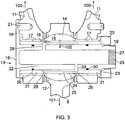
- the upper and lower links 7, 8 are connected by a pivotal joint 13 as shown in more detail in Figure 3 .
- the upper link 7 has a forked end with a pair of lugs 11, between which is received a single lug 12 at the end of the lower link 8. All three lugs have aligned bores with bearings to receive a pivot pin 13.
- the bearing between the lug of the lower link and the pin is a spherical bearing which is split to enable it to be assembled within a spherical cavity 15 within the lug.
- the inner surface 16 of the spherical bearing is cylindrical to receive the pin.
- the bearings within the outer lug comprise pairs of cylindrical bushes 17..
- the pivot pin has a head 18 at one end and a thread 19 at the other, and is inserted through the aligned bearings until the head 18 abuts the outer lug 11 at one end.
- a retaining nut 20 is then screwed onto the threaded portion of the pin extending from the second outer lug 11.
- the head 18 of the pivot pin has a radially extending flange 19 by which it is connected to the adj acent lug by a dowel 21 so as to restrain the pin from rotating.
- the pivot pin 13 consists of an inner cylindrical member 22 which carries the head 18 at one end and the threaded portion 19 at the other end, and a frangible sleeve 23 that fits over the inner member 22 between the head and the threaded portion. Portions of the sleeve 23 at each end are a close fit on the inner member and form lands 31, and a portion of the sleeve 24 therebetween has a reduced thickness so that its inner surface is spaced away from the inner member 22 to create a chamber 25. This central portion of reduced thickness is aligned with the central lug 12 and spherical bearing 14 so that it is exposed to a load applied between the upper and lower links. The outer ends of the central portion 24 are formed with additional internal channels 26 so as to reduce the thickness of the sleeve even further so that fracturing of the frangible sleeve 23 under load is most likely to occur at these points.
- the inner member 22 is formed with a blind bore 27 which is connected via radial passages 28 with the chamber 25 between the inner member and outer frangible sleeve.
- the whole of the volume of the bore 27 and chamber 25 and connecting passages 28 is filled with red dye and the open end of the bore is sealed by a plug 29.
- Ring seals 30 are provided between the inner member 22 and outer sleeve 23 at either end to prevent escape of red dye longitudinally therebetween.
- the pivot pin 13 On aircraft landing, the pivot pin 13 is subjected to landing forces. Specifically, the articulation link is subjected to a tensile load indicated by arrows 100 (indicating upwards forces applied to the lugs 11) and a downward force 101 subjected to the lug 12. This results in a downward force 102 being applied to the central portion 24 of the pivot pin by the lug 12 and bearing 14, and upwards forces 103 being applied to the outer ends of the pivot pin by the lugs 11.
- the pivot pin acts a shear pin and provides a simple, quick and accurate means of inspecting for reported cases of "hard landings". Also, the indication of a hard landing does not compromise aircraft safety or operation since the pivot pin 13 can continue to support landing loads even when the pivot pin has fractured. Inspection also requires no specialist tooling. Inspection should be possible within normal aircraft turnaround times - typically 4 hours.
- Identification of a limit load excedance would be identified quickly following the aircrew reporting the event by simple inspection of the joint. This inspection can be carried out with the aircraft parked normally on the ground and with no additional or special equipment. Any lack of freedom in the joint would indicate a deformation of the pivot pin and hence quarantine the MLGs for further inspection or removal.
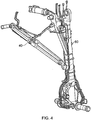
- the shear pin has been shown in the example above as a pivot pin in an articulation link, but a similar shear pin may be provided in other parts of a landing gear, for example as shown in Figures 4 and 5 , the shear pin can be used as a side stay pivot pin 40 or a drag stay pivot pin (not shown) to indicate if a lower load limit has been exceeded before the main pivot pin fails at a designed upper load limit.
- the pin need not be limited to use as a pivot member.
- it can also be used as a diaphragm pin 60 retaining an internal part of the shock absorber within the outer casing to react a load proportional to the inner pressures and to shear at a predetermined load limit.
- the shear pin may be positioned in some other part of an aircraft which is subjected to landing forces, such as a tail skid.
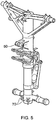
- the shear pin assembly can be used in an aircraft towing device, as shown at 70 in Figure 5 .
- the shear pin is subjected to aircraft towing forces, and can be inspected to determine whether the towing forces have exceeded a preset level which may be a lower warming level below a higher failure level at which other shear pins are designed to fail and release the load.
- shear pin has been illustrated for use on a winged aircraft, it may also be used on other aircraft such as a helicopter.
- the cavity 25 is filled with a red dye.
- the red dye may be replaced by another liquid indicator, by another flowable indicator such as a powder, or by an expanding foam.
Landscapes
- Engineering & Computer Science (AREA)
- General Engineering & Computer Science (AREA)
- Mechanical Engineering (AREA)
- Aviation & Aerospace Engineering (AREA)
- Physics & Mathematics (AREA)
- General Physics & Mathematics (AREA)
- Chemical & Material Sciences (AREA)
- Analytical Chemistry (AREA)
- Manufacturing & Machinery (AREA)
- Transportation (AREA)
- Health & Medical Sciences (AREA)
- Pathology (AREA)
- Immunology (AREA)
- Life Sciences & Earth Sciences (AREA)
- Biochemistry (AREA)
- General Health & Medical Sciences (AREA)
- Business, Economics & Management (AREA)
- Emergency Management (AREA)
- Force Measurement Appropriate To Specific Purposes (AREA)
- Testing Of Devices, Machine Parts, Or Other Structures Thereof (AREA)
- Glass Compositions (AREA)
- Water Treatment By Sorption (AREA)
- Thermally Insulated Containers For Foods (AREA)
- Vibration Dampers (AREA)
- Measurement Of Force In General (AREA)
Abstract
Description
- The present invention relates to a load indicator. Applications for the indicator include, but are not limited to, indicating a hard landing of an aircraft, and indication of excessive towing forces applied to an aircraft. The invention also relates to methods for inspecting an aircraft and inspecting an aircraft towing device.
- The cost of an Aircraft on Ground (AOG), for whatever reason, is very significant and the airline operators look to the manufacturers where possible to reduce the impact of this by planned maintenance and/or clearance for further flight until the next scheduled maintenance point can be reached. However, there are events where planning cannot help. One such event is a "Hard Landing".
- A "Hard Landing" occurs when, for whatever reason, the certified landing parameters are exceeded. This would normally be reported by the aircraft pilot and subsequently confirmed by inspection of the confirmed by inspection of the airframe structure and information extracted from the Digital Flight Data Recorder (DFDR). The problem lies in the time taken to analyse data confirm whether the event was truly a "Hard Landing" or not. This analysis can sometimes take up to 3 weeks to conclude and is not often tolerated by the aircraft operator.
-
US4392623 describes a fused connection adapted to fail under different overloads acting in different directions. The objective is to protect the fuel tank (primary wing structure) from rupture resulting from landing gear overload in either the vertical or horizontal directions. -
US5927646 describes an energy absorbing landing gear/tail skid including means for indicating the magnitude of impact loads. Impact loads effect plastic deformation of the device, and an elongate stem protrudes beyond a reference surface to provide a visual indication that the magnitude of impact loads has reached a threshold value. - Document
DE 33 43 495 A1 discloses a load indicator including all the features of the preamble of claim 1. - In accordance with a first aspect of the present invention, there is provided a load indicator according to claim 1.
- In accordance with a second aspect of the present invention, there is provided an assembly according to
claim 6. - The two components may comprise components of an aircraft landing gear including components of a side stay or drag stay or an articulation joint or a towing connection.
- The invention will now be described by way of example with reference to the accompanying drawings, in which:
-
Figure 1 is a view of an articulated landing gear; -
Figure 2 is a view of an articulation link of the landing gear ofFigure 1 ; -
Figure 3 is a cross section through a joint of the articulation link ofFigure 2 ; -
Figure 4 is a view of another landing gear showing other potential applications of the invention; and -
Figure 5 is a view of an aircraft towing device. -
Figure 1 shows a landing gear of an aircraft comprising a shock absorber strut 1 with upper andlower telescoping portions upper portion 2 being connectable to the airframe, thelower portion 3 carrying one ormore axles 4 by means of attachment to a pivotedbogie beam 5. Ahinged stay assembly 6 is connected between the upper portion of the shock absorber and the airframe and serves to stabilise the landing gear so that it may react load in the "down" position, yet is able to fold to allow the gear to retract. -
Articulation links bogie beam 5 and theupper part 2 of the shock absorber to react tension and thereby form a fulcrum for the bogie beam during the early part of landing. Thelower link 8 is attached between the forward part of thebogie beam 5 and theupper link 7, and theupper link 7 is attached between thelower link 8 and theupper part 2 of the shock absorber. A pitch trimmer 9 is mounted between the upper part 1 of the shock absorber and apoint 10 on theupper articulation link 7 close to its attachment to thelower articulation link 8 and serves to act as a hydraulic spring/damper to hold the articulation links in a position. The net result is a linkage mechanism that resists tension of thelower link 8, but allows it to rise when a compression load is applied. - The upper and
lower links pivotal joint 13 as shown in more detail inFigure 3 . Theupper link 7 has a forked end with a pair oflugs 11, between which is received asingle lug 12 at the end of thelower link 8. All three lugs have aligned bores with bearings to receive apivot pin 13. The bearing between the lug of the lower link and the pin is a spherical bearing which is split to enable it to be assembled within aspherical cavity 15 within the lug. Theinner surface 16 of the spherical bearing is cylindrical to receive the pin. The bearings within the outer lug comprise pairs ofcylindrical bushes 17.. The pivot pin has ahead 18 at one end and athread 19 at the other, and is inserted through the aligned bearings until thehead 18 abuts theouter lug 11 at one end. Aretaining nut 20 is then screwed onto the threaded portion of the pin extending from the secondouter lug 11. Thehead 18 of the pivot pin has a radially extendingflange 19 by which it is connected to the adj acent lug by adowel 21 so as to restrain the pin from rotating. - The
pivot pin 13 consists of an innercylindrical member 22 which carries thehead 18 at one end and the threadedportion 19 at the other end, and afrangible sleeve 23 that fits over theinner member 22 between the head and the threaded portion. Portions of thesleeve 23 at each end are a close fit on the inner member and formlands 31, and a portion of thesleeve 24 therebetween has a reduced thickness so that its inner surface is spaced away from theinner member 22 to create achamber 25. This central portion of reduced thickness is aligned with thecentral lug 12 andspherical bearing 14 so that it is exposed to a load applied between the upper and lower links. The outer ends of thecentral portion 24 are formed with additionalinternal channels 26 so as to reduce the thickness of the sleeve even further so that fracturing of thefrangible sleeve 23 under load is most likely to occur at these points. - The
inner member 22 is formed with ablind bore 27 which is connected viaradial passages 28 with thechamber 25 between the inner member and outer frangible sleeve. The whole of the volume of thebore 27 andchamber 25 and connectingpassages 28 is filled with red dye and the open end of the bore is sealed by aplug 29.Ring seals 30 are provided between theinner member 22 andouter sleeve 23 at either end to prevent escape of red dye longitudinally therebetween. - On aircraft landing, the
pivot pin 13 is subjected to landing forces. Specifically, the articulation link is subjected to a tensile load indicated by arrows 100 (indicating upwards forces applied to the lugs 11) and adownward force 101 subjected to thelug 12. This results in adownward force 102 being applied to thecentral portion 24 of the pivot pin by thelug 12 and bearing 14, and upwards forces 103 being applied to the outer ends of the pivot pin by thelugs 11. - When the
force 102 exceeds a certain level, thepivot pin 13 fractures in the region of thegrooves 26. This causes the red dye to be released from thecavity 25 and bleed out of the articulation link between the ends of the two links. - Thus, the pivot pin acts a shear pin and provides a simple, quick and accurate means of inspecting for reported cases of "hard landings". Also, the indication of a hard landing does not compromise aircraft safety or operation since the
pivot pin 13 can continue to support landing loads even when the pivot pin has fractured. Inspection also requires no specialist tooling. Inspection should be possible within normal aircraft turnaround times - typically 4 hours. - Identification of a limit load excedance would be identified quickly following the aircrew reporting the event by simple inspection of the joint. This inspection can be carried out with the aircraft parked normally on the ground and with no additional or special equipment. Any lack of freedom in the joint would indicate a deformation of the pivot pin and hence quarantine the MLGs for further inspection or removal.
- The shear pin has been shown in the example above as a pivot pin in an articulation link, but a similar shear pin may be provided in other parts of a landing gear, for example as shown in
Figures 4 and5 , the shear pin can be used as a sidestay pivot pin 40 or a drag stay pivot pin (not shown) to indicate if a lower load limit has been exceeded before the main pivot pin fails at a designed upper load limit. Also, the pin need not be limited to use as a pivot member. For example, it can also be used as adiaphragm pin 60 retaining an internal part of the shock absorber within the outer casing to react a load proportional to the inner pressures and to shear at a predetermined load limit. - Instead of being positioned in a landing gear, the shear pin may be positioned in some other part of an aircraft which is subjected to landing forces, such as a tail skid.
- Furthermore, the shear pin assembly can be used in an aircraft towing device, as shown at 70 in
Figure 5 . In this case the shear pin is subjected to aircraft towing forces, and can be inspected to determine whether the towing forces have exceeded a preset level which may be a lower warming level below a higher failure level at which other shear pins are designed to fail and release the load. - Although the shear pin has been illustrated for use on a winged aircraft, it may also be used on other aircraft such as a helicopter.
- In the examples shown, the
cavity 25 is filled with a red dye. In alternative embodiments, the red dye may be replaced by another liquid indicator, by another flowable indicator such as a powder, or by an expanding foam.
Claims (11)
- A load indicator comprising a load bearing assembly of first and second load bearing members (23, 22) connected together to bear a lateral load applied to the first member, wherein the first load bearing member (23) defines a cavity (25) with the second load bearing member (22) such that it is frangible above an indicator load, and the cavity (25) contains a flowable indicator which escapes from the cavity once the first load bearing member is fractured by said load, characterised in that the first load bearing member (23) is tubular and receives the second load bearing member (22) within it so that the two members engage via lands (31) at opposite ends and are spaced apart in a central region (24) to form the cavity (25), the second load bearing member (22) being arranged to continue to support said load following the first load bearing member (23) being fractured by said load.
- A load indicator as claimed in claim 1 in which a portion of the first load bearing member (23) is of a reduced thickness to render it frangible and to define the cavity (25).
- A load indicator as claimed in claim 2 in which both load bearing members (23, 22) comprise cylindrical members arranged concentrically.
- A load indicator as claimed in any one of claims 1 to 3 in which the cavity (25) includes an internal volume (27) within the second load bearing member (22).
- A load indicator as claimed in any one of the preceding claims configured as a load bearing pin to connect two components (7, 8) and to bear a load applied between the two components.
- A load indicator according to any preceding claim, wherein the flowable indicator is an indicator liquid.
- An assembly of two components and a load indicator configured as a load bearing pin as claimed in any one of claims 1 to 4, the pin engaging a pair of lugs (11) on one component (7) in alignment with the lands (31), and a lug (12) on the other component which lies between the pair of lugs (11), so as to be loaded by a lateral load when the two components are loaded in compression or tension.
- An assembly as claimed in claim 7 in which the two components (7, 8) comprise components of an aircraft landing gear.
- An assembly as claimed in claim 8 in which the two components (7, 8) comprise members of a side stay or an articulation joint or a towing connection.
- A method of detecting a hard landing of an aircraft using a load indicator as claimed in any of claims 1 to 5.
- A method of detecting an overload force in towing an aircraft using a load indicator as claimed in any of claims 1 to 5.
Applications Claiming Priority (2)
| Application Number | Priority Date | Filing Date | Title |
|---|---|---|---|
| GB0718296A GB2452938B (en) | 2007-09-19 | 2007-09-19 | Load indicator |
| PCT/GB2008/003187 WO2009037475A1 (en) | 2007-09-19 | 2008-09-19 | Load indicator |
Publications (2)
| Publication Number | Publication Date |
|---|---|
| EP2190744A1 EP2190744A1 (en) | 2010-06-02 |
| EP2190744B1 true EP2190744B1 (en) | 2012-04-18 |
Family
ID=38670176
Family Applications (1)
| Application Number | Title | Priority Date | Filing Date |
|---|---|---|---|
| EP08806342A Active EP2190744B1 (en) | 2007-09-19 | 2008-09-19 | Load indicator and method for detecting a hard landing or an overload force during towing of an aircraft |
Country Status (11)
| Country | Link |
|---|---|
| US (1) | US8539843B2 (en) |
| EP (1) | EP2190744B1 (en) |
| JP (1) | JP4873391B2 (en) |
| CN (1) | CN101808902B (en) |
| AT (1) | ATE554003T1 (en) |
| BR (1) | BRPI0816415A2 (en) |
| CA (1) | CA2699705C (en) |
| ES (1) | ES2386570T3 (en) |
| GB (1) | GB2452938B (en) |
| RU (1) | RU2478921C2 (en) |
| WO (1) | WO2009037475A1 (en) |
Cited By (1)
| Publication number | Priority date | Publication date | Assignee | Title |
|---|---|---|---|---|
| CN103983463A (en) * | 2014-04-17 | 2014-08-13 | 中国航空工业集团公司沈阳飞机设计研究所 | Method for verification test of combined loading of airframe and undercarriage |
Families Citing this family (29)
| Publication number | Priority date | Publication date | Assignee | Title |
|---|---|---|---|---|
| GB0723506D0 (en) * | 2007-12-03 | 2008-01-09 | Airbus Uk Ltd | Apparatus for indicating loading in a structure having exceeded a predetermined threshold |
| US8616146B2 (en) * | 2010-03-05 | 2013-12-31 | Goodrich Corporation | System for indicating an airplane hard landing |
| GB2478579A (en) * | 2010-03-11 | 2011-09-14 | Messier Dowty Ltd | Aircraft landing gear stop pad |
| GB2485803B (en) | 2010-11-24 | 2013-02-06 | Messier Dowty Ltd | Mechanical position indicator |
| US9103849B2 (en) * | 2011-06-10 | 2015-08-11 | Shockwatch, Inc. | Impact indicator |
| FR3000723B1 (en) * | 2013-01-10 | 2015-01-16 | Messier Bugatti Dowty | FUSE BODY FOR REUNNING TWO CAPS TO FORM A JOINT |
| US9499257B2 (en) * | 2013-06-17 | 2016-11-22 | Goodrich Corporation | Weight reducing landing gear features |
| CN110182373B (en) * | 2015-01-07 | 2023-01-10 | 洛德公司 | Bearing assemblies for aircraft engine mounts |
| EP3159260B1 (en) * | 2015-10-23 | 2019-11-27 | Safran Landing Systems UK Limited | Aircraft landing gear assembly including a health and usage monitoring system (hums) and method |
| US10272991B2 (en) * | 2016-06-23 | 2019-04-30 | Goodrich Corporation | Metallic composite joint |
| EP3336485B1 (en) | 2016-12-15 | 2020-09-23 | Safran Landing Systems UK Limited | Aircraft assembly including deflection sensor |
| JP6728089B2 (en) * | 2017-02-27 | 2020-07-22 | 三菱重工業株式会社 | Position determination device, position determination system including the same, position determination method, and position determination program |
| EP3379222B1 (en) | 2017-03-22 | 2020-12-30 | Methode Electronics Malta Ltd. | Magnetoelastic based sensor assembly |
| US11135882B2 (en) | 2018-02-27 | 2021-10-05 | Methode Electronics, Inc. | Towing systems and methods using magnetic field sensing |
| US11221262B2 (en) | 2018-02-27 | 2022-01-11 | Methode Electronics, Inc. | Towing systems and methods using magnetic field sensing |
| US11084342B2 (en) | 2018-02-27 | 2021-08-10 | Methode Electronics, Inc. | Towing systems and methods using magnetic field sensing |
| US11491832B2 (en) | 2018-02-27 | 2022-11-08 | Methode Electronics, Inc. | Towing systems and methods using magnetic field sensing |
| US11014417B2 (en) | 2018-02-27 | 2021-05-25 | Methode Electronics, Inc. | Towing systems and methods using magnetic field sensing |
| DE18907724T1 (en) | 2018-02-27 | 2021-03-25 | Methode Electronics, Inc. | Towing systems and methods using magnetic field measurement |
| US11130563B2 (en) * | 2018-11-07 | 2021-09-28 | The Boeing Company | Monolithic outboard gear beam support fitting |
| CA3060756A1 (en) * | 2018-11-07 | 2020-05-07 | Bombardier Inc. | Hard landing indicator for an aircraft landing gear |
| CN109979037A (en) * | 2019-03-19 | 2019-07-05 | 四川函钛科技有限公司 | QAR parametric synthesis visual analysis method and system |
| US11124293B2 (en) | 2019-04-23 | 2021-09-21 | Goodrich Corporation | Integral bracket manifold for landing gear assemblies |
| KR102325331B1 (en) | 2019-12-20 | 2021-11-10 | 한화토탈 주식회사 | Method for isobutylene from tert-butanol |
| CN112429253B (en) * | 2020-12-14 | 2022-10-11 | 江西洪都航空工业集团有限责任公司 | Acceleration heavy landing indicator |
| CN113062934B (en) * | 2021-04-23 | 2022-05-27 | 中铁工程装备集团有限公司 | Shield constructs owner and drives speed reducer overload protection ware and shield constructs machine |
| CN114674550B (en) * | 2022-03-29 | 2024-05-07 | 中航飞机起落架有限责任公司 | Airplane main strut running-in test device and test method |
| FR3136264B1 (en) * | 2022-06-03 | 2024-07-05 | Safran Landing Systems | Device for blocking a stop pin |
| EP4428031B1 (en) | 2023-03-06 | 2026-05-13 | Lilium GmbH | Landing gear for a vertical take-off and landing aircraft |
Family Cites Families (27)
| Publication number | Priority date | Publication date | Assignee | Title |
|---|---|---|---|---|
| US2960289A (en) * | 1958-07-07 | 1960-11-15 | Cleveland Pneumatic Ind Inc | Aircraft landing gear |
| GB1027395A (en) * | 1962-02-16 | 1966-04-27 | Nat Res Dev | Controlled fluid lubricated bearings |
| US3237590A (en) * | 1963-09-13 | 1966-03-01 | Bendix Corp | Strain gauge means |
| SU467246A1 (en) * | 1973-02-14 | 1975-04-15 | Краснодарский Филиал Вниимонтаж Спецстрой Всесоюзного Научно-Исследовательского Института По Монтажным И Специальным Строительным Работам | Device for controlling the tightening forces of threaded connections |
| US3845919A (en) * | 1974-01-07 | 1974-11-05 | Boeing Co | Landing gear truck pitch damping |
| US3948141A (en) * | 1974-08-20 | 1976-04-06 | Katsumi Shinjo | Load indicating washer |
| JPS5746842A (en) * | 1980-08-15 | 1982-03-17 | Teijin Ltd | High frequency welding method |
| US4392623A (en) * | 1980-12-22 | 1983-07-12 | The Boeing Company | Fused connection adapted to fail under different overloads acting in different directions |
| FR2511103A1 (en) * | 1981-08-10 | 1983-02-11 | Aerospatiale | COMPONENTS COMPRISING A PLASTIC DEFORMATION AND / OR EFFORT LIMITATION ENERGY ABSORPTION DEVICE, AND AERODYNES LANDING TRAINS EQUIPPED WITH SUCH COMPONENTS |
| US4373862A (en) * | 1981-10-26 | 1983-02-15 | United Technologies Corporation | Rotor blade shaft integrity monitoring system |
| US4447388A (en) * | 1981-11-30 | 1984-05-08 | The United States Of America As Represented By The United States Department Of Energy | Bolt failure detection |
| DE3343495A1 (en) * | 1983-12-01 | 1985-07-18 | Paul 7936 Allmendingen Friese | Tensile fracture display |
| JPS60209137A (en) * | 1984-04-03 | 1985-10-21 | Topy Ind Ltd | Predicting method of fatigue damage |
| US4698623A (en) * | 1984-11-07 | 1987-10-06 | Smith Richard G | Overload detection apparatus |
| JPS6261898A (en) * | 1985-09-10 | 1987-03-18 | ニユ−モ・コ−ポレ−シヨン | Landing gear |
| US4869444A (en) * | 1986-09-30 | 1989-09-26 | The Boeing Company | Adjustable two-stage aircraft landing gear system |
| GB8815826D0 (en) * | 1988-07-04 | 1988-08-10 | Westland Helicopters | Method & apparatus for detecting cracks |
| SU1658186A1 (en) * | 1989-03-20 | 1991-06-23 | Киевский Политехнический Институт Им.50-Летия Великой Октябрьской Социалистической Революции | Vibration overload indicator |
| JP3037370B2 (en) * | 1990-07-11 | 2000-04-24 | 東芝エンジニアリング株式会社 | Pin type load cell |
| AU5167396A (en) | 1995-09-14 | 1997-04-01 | Sikorsky Aircraft Corporation | Energy absorbing landing gear/tail skid including means for indicating the magnitude of impact loads |
| GB9828475D0 (en) * | 1998-12-24 | 1999-02-17 | British Aerospace | Load measurement |
| AUPR001800A0 (en) | 2000-09-08 | 2000-10-05 | Structural Monitoring Systems Ltd | Method and apparatus for monitoring the integrity of structures |
| GB0428378D0 (en) * | 2004-12-24 | 2005-02-02 | Airbus Uk Ltd | Apparatus and method for measuring loads sustained by a bearing pin |
| US7193530B2 (en) * | 2005-03-29 | 2007-03-20 | Nance C Kirk | Aircraft landing gear automated inspection and life limitation escalation system and method |
| GB2452939B (en) * | 2007-09-19 | 2011-09-07 | Messier Dowty Ltd | Overload detection |
| GB2453554B (en) * | 2007-10-09 | 2012-03-14 | Messier Dowty Ltd | Load detection in an aircraft landing gear |
| GB0723506D0 (en) * | 2007-12-03 | 2008-01-09 | Airbus Uk Ltd | Apparatus for indicating loading in a structure having exceeded a predetermined threshold |
-
2007
- 2007-09-19 GB GB0718296A patent/GB2452938B/en not_active Expired - Fee Related
-
2008
- 2008-09-19 US US12/678,970 patent/US8539843B2/en active Active
- 2008-09-19 AT AT08806342T patent/ATE554003T1/en active
- 2008-09-19 RU RU2010115338/11A patent/RU2478921C2/en not_active IP Right Cessation
- 2008-09-19 EP EP08806342A patent/EP2190744B1/en active Active
- 2008-09-19 CA CA2699705A patent/CA2699705C/en not_active Expired - Fee Related
- 2008-09-19 ES ES08806342T patent/ES2386570T3/en active Active
- 2008-09-19 JP JP2010525431A patent/JP4873391B2/en not_active Expired - Fee Related
- 2008-09-19 BR BRPI0816415-0A2A patent/BRPI0816415A2/en not_active IP Right Cessation
- 2008-09-19 WO PCT/GB2008/003187 patent/WO2009037475A1/en not_active Ceased
- 2008-09-19 CN CN2008801077906A patent/CN101808902B/en active Active
Cited By (2)
| Publication number | Priority date | Publication date | Assignee | Title |
|---|---|---|---|---|
| CN103983463A (en) * | 2014-04-17 | 2014-08-13 | 中国航空工业集团公司沈阳飞机设计研究所 | Method for verification test of combined loading of airframe and undercarriage |
| CN103983463B (en) * | 2014-04-17 | 2016-08-24 | 中国航空工业集团公司沈阳飞机设计研究所 | A kind of airframe and the checking test method of undercarriage combination loading |
Also Published As
| Publication number | Publication date |
|---|---|
| GB2452938B (en) | 2011-08-10 |
| CN101808902B (en) | 2013-04-24 |
| EP2190744A1 (en) | 2010-06-02 |
| GB2452938A (en) | 2009-03-25 |
| CN101808902A (en) | 2010-08-18 |
| GB0718296D0 (en) | 2007-10-31 |
| JP4873391B2 (en) | 2012-02-08 |
| US20100257946A1 (en) | 2010-10-14 |
| ES2386570T3 (en) | 2012-08-23 |
| CA2699705A1 (en) | 2009-03-26 |
| BRPI0816415A2 (en) | 2015-03-03 |
| WO2009037475A1 (en) | 2009-03-26 |
| US8539843B2 (en) | 2013-09-24 |
| RU2478921C2 (en) | 2013-04-10 |
| CA2699705C (en) | 2014-11-18 |
| RU2010115338A (en) | 2011-10-27 |
| ATE554003T1 (en) | 2012-05-15 |
| JP2010539509A (en) | 2010-12-16 |
Similar Documents
| Publication | Publication Date | Title |
|---|---|---|
| US8539843B2 (en) | Load indicator | |
| EP2993128B1 (en) | System for indicating an airplane hard landing | |
| EP2190737B1 (en) | Overload detection for an aircraft landing gear | |
| US7193530B2 (en) | Aircraft landing gear automated inspection and life limitation escalation system and method | |
| EP2350590B1 (en) | Load indicator | |
| EP3342703B1 (en) | Landing gear with threadless cardan joint | |
| EP0319051A2 (en) | Pivotally mounted high energy absorbing aircraft tail skid assembly having predetermined failure mode | |
| JPH10508813A (en) | Shock resistant landing gear for aircraft | |
| CN109506908B (en) | Tail end load loading device for fatigue test of tail section test piece | |
| US12600466B2 (en) | Landing gear assemblies, rotorcraft and rotorcraft methods | |
| EP4717596A1 (en) | A swivel device for connecting human and/or non-human cargo to a rotorcraft | |
| Crist et al. | Helicopter Landing Gear Design and Test Criteria Investigation | |
| US10208787B2 (en) | Fusible member intended to join two yokes to form a hinge | |
| Phillips | Technology Innovations for Aircraft'Hard Landing'Events. | |
| Shen et al. | Research on the breaking away design of civil aircraft main gear | |
| Timmerman et al. | Qualification and certification of Special Patrol Insertion & Extraction (SPIE) equipment for military helicopters | |
| Leski et al. | The assessment of fatigue-life resources of the PZL-130 Orlik’s structure | |
| EP3127818A1 (en) | Computer system for determining approach of aircraft and aircraft |
Legal Events
| Date | Code | Title | Description |
|---|---|---|---|
| PUAI | Public reference made under article 153(3) epc to a published international application that has entered the european phase |
Free format text: ORIGINAL CODE: 0009012 |
|
| 17P | Request for examination filed |
Effective date: 20100324 |
|
| AK | Designated contracting states |
Kind code of ref document: A1 Designated state(s): AT BE BG CH CY CZ DE DK EE ES FI FR GB GR HR HU IE IS IT LI LT LU LV MC MT NL NO PL PT RO SE SI SK TR |
|
| AX | Request for extension of the european patent |
Extension state: AL BA MK RS |
|
| DAX | Request for extension of the european patent (deleted) | ||
| 17Q | First examination report despatched |
Effective date: 20101222 |
|
| RTI1 | Title (correction) |
Free format text: LOAD INDICATOR AND THOD FOR DETECTING A HARD LAN DING OR AN OVERLOAD FORCE DURING TOWING OF AN AIRCRAFT |
|
| GRAP | Despatch of communication of intention to grant a patent |
Free format text: ORIGINAL CODE: EPIDOSNIGR1 |
|
| RTI1 | Title (correction) |
Free format text: LOAD INDICATOR AND METHOD FOR DETECTING A HARD LANDING OR AN OVERLOAD FORCE DURING TOWING OF AN AIRCRAFT |
|
| GRAS | Grant fee paid |
Free format text: ORIGINAL CODE: EPIDOSNIGR3 |
|
| GRAA | (expected) grant |
Free format text: ORIGINAL CODE: 0009210 |
|
| AK | Designated contracting states |
Kind code of ref document: B1 Designated state(s): AT BE BG CH CY CZ DE DK EE ES FI FR GB GR HR HU IE IS IT LI LT LU LV MC MT NL NO PL PT RO SE SI SK TR |
|
| REG | Reference to a national code |
Ref country code: GB Ref legal event code: FG4D |
|
| REG | Reference to a national code |
Ref country code: CH Ref legal event code: EP |
|
| REG | Reference to a national code |
Ref country code: IE Ref legal event code: FG4D |
|
| REG | Reference to a national code |
Ref country code: AT Ref legal event code: REF Ref document number: 554003 Country of ref document: AT Kind code of ref document: T Effective date: 20120515 |
|
| REG | Reference to a national code |
Ref country code: DE Ref legal event code: R096 Ref document number: 602008015012 Country of ref document: DE Effective date: 20120614 |
|
| REG | Reference to a national code |
Ref country code: NL Ref legal event code: VDEP Effective date: 20120418 |
|
| REG | Reference to a national code |
Ref country code: ES Ref legal event code: FG2A Ref document number: 2386570 Country of ref document: ES Kind code of ref document: T3 Effective date: 20120823 |
|
| REG | Reference to a national code |
Ref country code: AT Ref legal event code: MK05 Ref document number: 554003 Country of ref document: AT Kind code of ref document: T Effective date: 20120418 |
|
| LTIE | Lt: invalidation of european patent or patent extension |
Effective date: 20120418 |
|
| PG25 | Lapsed in a contracting state [announced via postgrant information from national office to epo] |
Ref country code: FI Free format text: LAPSE BECAUSE OF FAILURE TO SUBMIT A TRANSLATION OF THE DESCRIPTION OR TO PAY THE FEE WITHIN THE PRESCRIBED TIME-LIMIT Effective date: 20120418 Ref country code: PL Free format text: LAPSE BECAUSE OF FAILURE TO SUBMIT A TRANSLATION OF THE DESCRIPTION OR TO PAY THE FEE WITHIN THE PRESCRIBED TIME-LIMIT Effective date: 20120418 Ref country code: LT Free format text: LAPSE BECAUSE OF FAILURE TO SUBMIT A TRANSLATION OF THE DESCRIPTION OR TO PAY THE FEE WITHIN THE PRESCRIBED TIME-LIMIT Effective date: 20120418 Ref country code: NO Free format text: LAPSE BECAUSE OF FAILURE TO SUBMIT A TRANSLATION OF THE DESCRIPTION OR TO PAY THE FEE WITHIN THE PRESCRIBED TIME-LIMIT Effective date: 20120718 Ref country code: CY Free format text: LAPSE BECAUSE OF FAILURE TO SUBMIT A TRANSLATION OF THE DESCRIPTION OR TO PAY THE FEE WITHIN THE PRESCRIBED TIME-LIMIT Effective date: 20120418 Ref country code: SE Free format text: LAPSE BECAUSE OF FAILURE TO SUBMIT A TRANSLATION OF THE DESCRIPTION OR TO PAY THE FEE WITHIN THE PRESCRIBED TIME-LIMIT Effective date: 20120418 Ref country code: IS Free format text: LAPSE BECAUSE OF FAILURE TO SUBMIT A TRANSLATION OF THE DESCRIPTION OR TO PAY THE FEE WITHIN THE PRESCRIBED TIME-LIMIT Effective date: 20120818 |
|
| PG25 | Lapsed in a contracting state [announced via postgrant information from national office to epo] |
Ref country code: PT Free format text: LAPSE BECAUSE OF FAILURE TO SUBMIT A TRANSLATION OF THE DESCRIPTION OR TO PAY THE FEE WITHIN THE PRESCRIBED TIME-LIMIT Effective date: 20120820 Ref country code: SI Free format text: LAPSE BECAUSE OF FAILURE TO SUBMIT A TRANSLATION OF THE DESCRIPTION OR TO PAY THE FEE WITHIN THE PRESCRIBED TIME-LIMIT Effective date: 20120418 Ref country code: LV Free format text: LAPSE BECAUSE OF FAILURE TO SUBMIT A TRANSLATION OF THE DESCRIPTION OR TO PAY THE FEE WITHIN THE PRESCRIBED TIME-LIMIT Effective date: 20120418 Ref country code: GR Free format text: LAPSE BECAUSE OF FAILURE TO SUBMIT A TRANSLATION OF THE DESCRIPTION OR TO PAY THE FEE WITHIN THE PRESCRIBED TIME-LIMIT Effective date: 20120719 Ref country code: HR Free format text: LAPSE BECAUSE OF FAILURE TO SUBMIT A TRANSLATION OF THE DESCRIPTION OR TO PAY THE FEE WITHIN THE PRESCRIBED TIME-LIMIT Effective date: 20120418 |
|
| PG25 | Lapsed in a contracting state [announced via postgrant information from national office to epo] |
Ref country code: BE Free format text: LAPSE BECAUSE OF FAILURE TO SUBMIT A TRANSLATION OF THE DESCRIPTION OR TO PAY THE FEE WITHIN THE PRESCRIBED TIME-LIMIT Effective date: 20120418 |
|
| PGFP | Annual fee paid to national office [announced via postgrant information from national office to epo] |
Ref country code: IT Payment date: 20120926 Year of fee payment: 5 Ref country code: ES Payment date: 20120926 Year of fee payment: 5 |
|
| PG25 | Lapsed in a contracting state [announced via postgrant information from national office to epo] |
Ref country code: CZ Free format text: LAPSE BECAUSE OF FAILURE TO SUBMIT A TRANSLATION OF THE DESCRIPTION OR TO PAY THE FEE WITHIN THE PRESCRIBED TIME-LIMIT Effective date: 20120418 Ref country code: EE Free format text: LAPSE BECAUSE OF FAILURE TO SUBMIT A TRANSLATION OF THE DESCRIPTION OR TO PAY THE FEE WITHIN THE PRESCRIBED TIME-LIMIT Effective date: 20120418 Ref country code: SK Free format text: LAPSE BECAUSE OF FAILURE TO SUBMIT A TRANSLATION OF THE DESCRIPTION OR TO PAY THE FEE WITHIN THE PRESCRIBED TIME-LIMIT Effective date: 20120418 Ref country code: NL Free format text: LAPSE BECAUSE OF FAILURE TO SUBMIT A TRANSLATION OF THE DESCRIPTION OR TO PAY THE FEE WITHIN THE PRESCRIBED TIME-LIMIT Effective date: 20120418 Ref country code: DK Free format text: LAPSE BECAUSE OF FAILURE TO SUBMIT A TRANSLATION OF THE DESCRIPTION OR TO PAY THE FEE WITHIN THE PRESCRIBED TIME-LIMIT Effective date: 20120418 Ref country code: RO Free format text: LAPSE BECAUSE OF FAILURE TO SUBMIT A TRANSLATION OF THE DESCRIPTION OR TO PAY THE FEE WITHIN THE PRESCRIBED TIME-LIMIT Effective date: 20120418 Ref country code: AT Free format text: LAPSE BECAUSE OF FAILURE TO SUBMIT A TRANSLATION OF THE DESCRIPTION OR TO PAY THE FEE WITHIN THE PRESCRIBED TIME-LIMIT Effective date: 20120418 |
|
| PLBE | No opposition filed within time limit |
Free format text: ORIGINAL CODE: 0009261 |
|
| STAA | Information on the status of an ep patent application or granted ep patent |
Free format text: STATUS: NO OPPOSITION FILED WITHIN TIME LIMIT |
|
| 26N | No opposition filed |
Effective date: 20130121 |
|
| PG25 | Lapsed in a contracting state [announced via postgrant information from national office to epo] |
Ref country code: MC Free format text: LAPSE BECAUSE OF NON-PAYMENT OF DUE FEES Effective date: 20120930 |
|
| REG | Reference to a national code |
Ref country code: CH Ref legal event code: PL |
|
| REG | Reference to a national code |
Ref country code: DE Ref legal event code: R097 Ref document number: 602008015012 Country of ref document: DE Effective date: 20130121 |
|
| REG | Reference to a national code |
Ref country code: IE Ref legal event code: MM4A |
|
| PG25 | Lapsed in a contracting state [announced via postgrant information from national office to epo] |
Ref country code: CH Free format text: LAPSE BECAUSE OF NON-PAYMENT OF DUE FEES Effective date: 20120930 Ref country code: BG Free format text: LAPSE BECAUSE OF FAILURE TO SUBMIT A TRANSLATION OF THE DESCRIPTION OR TO PAY THE FEE WITHIN THE PRESCRIBED TIME-LIMIT Effective date: 20120718 Ref country code: LI Free format text: LAPSE BECAUSE OF NON-PAYMENT OF DUE FEES Effective date: 20120930 Ref country code: IE Free format text: LAPSE BECAUSE OF NON-PAYMENT OF DUE FEES Effective date: 20120919 |
|
| PG25 | Lapsed in a contracting state [announced via postgrant information from national office to epo] |
Ref country code: MT Free format text: LAPSE BECAUSE OF FAILURE TO SUBMIT A TRANSLATION OF THE DESCRIPTION OR TO PAY THE FEE WITHIN THE PRESCRIBED TIME-LIMIT Effective date: 20120418 |
|
| PG25 | Lapsed in a contracting state [announced via postgrant information from national office to epo] |
Ref country code: TR Free format text: LAPSE BECAUSE OF FAILURE TO SUBMIT A TRANSLATION OF THE DESCRIPTION OR TO PAY THE FEE WITHIN THE PRESCRIBED TIME-LIMIT Effective date: 20120418 |
|
| PG25 | Lapsed in a contracting state [announced via postgrant information from national office to epo] |
Ref country code: LU Free format text: LAPSE BECAUSE OF NON-PAYMENT OF DUE FEES Effective date: 20120919 |
|
| PG25 | Lapsed in a contracting state [announced via postgrant information from national office to epo] |
Ref country code: HU Free format text: LAPSE BECAUSE OF FAILURE TO SUBMIT A TRANSLATION OF THE DESCRIPTION OR TO PAY THE FEE WITHIN THE PRESCRIBED TIME-LIMIT Effective date: 20080919 |
|
| PG25 | Lapsed in a contracting state [announced via postgrant information from national office to epo] |
Ref country code: IT Free format text: LAPSE BECAUSE OF NON-PAYMENT OF DUE FEES Effective date: 20130919 |
|
| REG | Reference to a national code |
Ref country code: ES Ref legal event code: FD2A Effective date: 20141007 |
|
| PG25 | Lapsed in a contracting state [announced via postgrant information from national office to epo] |
Ref country code: ES Free format text: LAPSE BECAUSE OF NON-PAYMENT OF DUE FEES Effective date: 20130920 |
|
| REG | Reference to a national code |
Ref country code: FR Ref legal event code: PLFP Year of fee payment: 9 |
|
| REG | Reference to a national code |
Ref country code: FR Ref legal event code: CD Owner name: SAFRAN LANDING SYSTEMS UK LTD, GB Effective date: 20170404 |
|
| REG | Reference to a national code |
Ref country code: FR Ref legal event code: PLFP Year of fee payment: 10 |
|
| REG | Reference to a national code |
Ref country code: FR Ref legal event code: PLFP Year of fee payment: 11 |
|
| PGFP | Annual fee paid to national office [announced via postgrant information from national office to epo] |
Ref country code: DE Payment date: 20210818 Year of fee payment: 14 |
|
| REG | Reference to a national code |
Ref country code: DE Ref legal event code: R119 Ref document number: 602008015012 Country of ref document: DE |
|
| PG25 | Lapsed in a contracting state [announced via postgrant information from national office to epo] |
Ref country code: DE Free format text: LAPSE BECAUSE OF NON-PAYMENT OF DUE FEES Effective date: 20230401 |
|
| PGFP | Annual fee paid to national office [announced via postgrant information from national office to epo] |
Ref country code: GB Payment date: 20250923 Year of fee payment: 18 |
|
| PGFP | Annual fee paid to national office [announced via postgrant information from national office to epo] |
Ref country code: FR Payment date: 20250923 Year of fee payment: 18 |